Abstract
As an emerging technique of wireless communication, visible light communication is experiencing a boom in the global communications field, and the dream of accessing the Internet with light is fast becoming a reality. Multiple input multiple output, which is a key technique in radio frequency communication, can multiply channel capacity. However, it suffers the trouble of too large channel correlation when directly applied to visible light communication. The aims of this paper were to investigate spatial modulation and cooperative communication, then put forward a cooperative strategy based on space–time labeling diversity for indoor visible light communication systems to achieve high reliability. This scheme was conceived in two steps: (1) a cooperative indoor visible light communication system with a source luminaire, a relay luminaire, and a destination receiver was set up by employing the idea of cooperative transmission. Relative to the destination receiver, these two luminaires can be symmetric or asymmetric in geographical distribution. (2) Space–time labeling diversity of the constellations at the source luminaire was re-adjusted at the relay luminaire to enlarge the product of the distance of corresponding points on both constellations and was introduced on the basis of spatial modulation. Furthermore, total bit error ratio of the proposed cooperative indoor visible light communication system was derived. This scheme was implemented through Monte Carlo simulation. Evaluations of performance demonstrated the superiority of the cooperative strategy based on space–time labeling diversity over conventional optical transmission schemes. The presented approach in this paper could be of some value and interest to those who are working on visible light communication devices.
1. Introduction
Visible light communication (VLC), which has the advantages of being high speed, license-free, anti-electromagnetic interference, and high security, is receiving more and more global attention [1,2]. In the era of 4th/5th generation wireless communication, VLC is even more considered to be a mutual enhancement to radio frequency (RF) communication, especially for indoor applications. In recent years, achieving high speed data transmission in a VLC system has been a research focus. Introducing multiple input multiple output (MIMO) into a VLC system can multiply channel capacity and spectrum utilization without increasing system bandwidth. However, in a VLC system, channel correlation is even larger than that in RF communication systems. The reliability of system will be greatly reduced when MIMO is directly applied to VLC. Cooperative transmission can effectively improve reliability of wireless communication systems by resisting channel fading. It is also called a virtual MIMO. The distributed layout of luminaires in indoor VLC systems is very suitable for employing cooperative transmission. It provides an effective way in practice to implement MIMO in indoor VLC systems.
Many studies have focused on the use of spatial modulation (SM) to improve spectrum utilization and reliability in VLC systems. In [3], SM was first applied to VLC systems. As a result, the data rate of this modulation was higher than that of traditional optical modulations, such as on-off keying modulation or pulse position modulation, and spectrum utilization was significantly improved. In [4], a generalized SM scheme which could activate multiple light emitting diodes (LEDs) to simultaneously transmit information was proposed in VLC systems. Eventually, this scheme could not only improve spectrum utilization, but also reduce symbol error rate. In VLC, multipath effects can destroy the orthogonality of subcarriers of orthogonal frequency division multiplexing optical symbols during transmission and influence demodulation at the receiving device. This is called inter channel interference (ICI). To eliminate ICI and improve spectrum efficiency of VLC systems, an index-based optical spatial modulation (OSM) scheme was proposed in [5]. In [6], a channel-adaptation spatial modulation (CASM) that channel-adapted spatial constellations with maximum size of the best combinations of active LEDs when ICI was below a given threshold was proposed. It established a general criterion of balancing spectral efficiency and error performance by analyzing special features of the system with the channel state information known for luminaires, and was very suitable for large-scale MIMO VLC systems. As a result, performance of bit error rate (BER) was better than conventional OSMs, and the greater the channel correlation, the more obvious advantages of CASM. To eliminate the adverse effects of random channel assignment in conventional OSM systems, a novel SM scheme based on index modulation was proposed in [7]. Both the active LED index and the modulated information were transmitted on a designed symbol through the best VLC channel. As a result, the complexity of the receiving device could be greatly reduced and significant performance improvement could be achieved compared to conventional OSM with random channel assignment. In conventional OSM or optical spatial multiplexing (OSMP), symbols sent by LEDs are independently generated from constellations, and this is not optimal when considering energy utilization. Therefore, a novel constellation design where two symbols from two spaces in the MIMO VLC system collaborate so closely that the average optical power is minimized under the constraint that the minimum Euclidean distance is fixed was proposed in [8]. Though spatial diversity was adopted in traditional approaches and the novel design, the latter has a better BER performance than conventional OSM or OSMP. In [9], the design and implementation methodology of a spatially modulated VLC MIMO system using eight power LEDs as transmitters and eight photodiodes as receivers were described, and furthermore, spatial modulation techniques and special lens arrangements were introduced to mitigate co-channel interference (CCI) and increase the robustness of system. The literature above demonstrated that the use of SM enables MIMO techniques to play a role in VLC systems. However, in order to further improve performance of VLC systems, several approaches tried to make use of cooperative transmission. In [10], an indoor cooperative incremental hybrid decode–amplify–forward (IHDAF) protocol for a SM VLC system was proposed, which has a significant performance improvement in resisting channel propagation compared with conventional IHDAF. In [11], a space frequency block code with frequency-switched transmit diversity in indoor VLC systems was proposed. It can mitigate CCI through cooperative transmission, which occurs when the coverage areas of LEDs are overlapped and source luminaires send different information, and thereby improve the reliability of the system.
The main aim of this paper was to put forward a cooperative strategy based on space–time labeling diversity for indoor VLC systems to achieve high reliability. This scheme was implemented through a Monte Carlo simulation. Finally, we presented BER performance comparisons with other schemes in indoor VLC systems.
The main contributions of this paper were as follows:
(1) Searching and investigating various SM schemes which have been proposed in VLC systems in recent years.
(2) Employing the idea of cooperative transmission in indoor VLC systems to realize MIMO in practice.
(3) Putting forward a space–time labeling diversity structure for cooperative indoor VLC systems.
The key achievement of this paper was to employ the idea of cooperative transmission to construct virtual MIMO for indoor VLC systems to eliminate channel correlation in MIMO VLC systems. Moreover, a new diversity structure of space–time labeling was designed to further improve the reliability of the system.
This paper is organized as follows. Section 2 presents related knowledge and theory with regard to cooperative communication and space–time labeling diversity. Section 3 first describes a model of cooperative indoor VLC systems, and then introduces space–time labeling diversity into the constructed model, finally deriving the BER of the proposed cooperative indoor VLC system. Monte Carlo simulations and analyses of results are found in Section 4. Finally, the conclusions of this paper are summarized in Section 5.
2. Related Knowledge and Theory
2.1. Cooperative Communication
Cooperative communication is a new form of spatial diversity, in which gain of diversity is achieved via cooperation of in-cell terminals [12], that is, in each cell, each terminal has at least a partner. The model of cooperative channel is depicted in Figure 1, and it is supposed that each terminal has only a partner. Each terminal receives an attenuated and noisy version of its partner’s transmitted signal and uses it in conjunction with its own data to construct new transmitted signals. The destination terminal receives a noisy version of sum of attenuated signals of both terminals. The mathematical formulation of the model can be expressed as:
where , and are received signals at the destination terminal, terminal1, and terminal2 during a time slot. is the signal transmitted by terminal , and is the additive channel noise at the destination terminal, terminal1, and terminal 2. The fading coefficient remains constant over at least a time slot. is the transmit power at terminal .
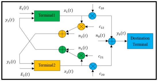
Figure 1.
The model of the cooperative channel.
2.2. Space–Time Labeling Diversity
In space–time labeling diversity, the minimum Euclidean distance product of the space–time block code is adopted instead of bit interleaving or coding to maximize the coding gain of space–time coding. The principle is described as follows. We assume a MIMO system of space–time labeling diversity with transmitting antennas and receiving antennas, and any two transmitting antennas are activated to transmit information [13]. The original data were divided into two bitstreams, which are called and , where , is the order for modulation. Then and sequentially enter into two mappers of constellations, which are called mapper1 of the constellation and mapper2 of the constellation. They are also described as and . After and enter into two mappers, mapper1 of the constellation maps them onto points of the multiple quadrature amplitude modulation/multiple phase shift keying (M-QAM/M-PSK) constellation, and the output will produce two modulated signals, which are described as follows, where ,
The mapper2 of the constellation maps them onto points of the M-QAM/M-PSK constellation which are on the complex plane, and the output will produce two modulated signals, which are described as follows,
It is assumed the average power of modulated signals is . In space–time labeling diversity, although the design of mapper1 of the constellation follows the criterion of traditional coding, the design of mapper2 of the constellation guarantees that space–time labeling diversity is different from others. After and are mapped, two transmitting antennas which are activated will separately transmit signals and in the first time slot, and then separately transmit signals and in the second time slot. When the channel between transmitter and receiver is Rayleigh flat fast fading, the received signal vector of the system of in time slot is
where , , is the average signal to noise ratio (SNR) of every receive antenna, and is the channel fading coefficient of system of in time slot ,
where , is the vector of additive Gaussian white noise of channel of . and are respectively the independent and identically distributed complex Gaussian random variables with distributions of and . The codeword of space–time labeling diversity is defined as,
Moreover, the sets of all ordered signal pairs of are contained in . At the receiver, an optimal detector based on a maximum likelihood (ML) criterion which determinates transmitted data according to the value of maximum transition probability is used to determine transmitted signals. The ML is defined as
3. Cooperative Strategy Based on Space–Time Labeling Diversity for Indoor VLC Systems
3.1. Description of the Cooperative Indoor VLC System
An ordinary study room is considered with dimensions of , and equipped with luminaires and furniture items, as shown in Figure 2. In this room, there are numerous luminaires; one is the main luminaire for the whole space at the ceiling, which is also called the source luminaire (S), and the others are mounted on desks to provide cooperative light, which are also called relay luminaires (R). S has direct access to the backbone network, e.g., CHINANET. Relay luminaires are selected according to the distance between S and R. S will choose relay luminaires according to the channel correlation coefficient of the transmitting domain between S and R. The destination receiver (D) is in the form of a USB device which is connected to a computer. In this room, S is only fixed with the module for transmitting VLC signals, and all relay luminaires are fixed with modules for transmitting and receiving VLC signals, while D is only fixed with the module for receiving VLC signals.
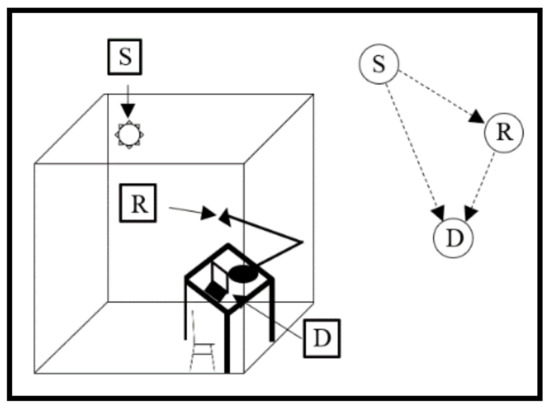
Figure 2.
Cooperative indoor visible light communication (VLC) system with luminaires.
3.2. Cooperative Strategy Based on Space–Time Labeling Diversity for Indoor VLC Systems
For simplicity, a cooperative indoor VLC system with three terminals was studied in this paper, which were S, R, and D. The process of cooperative transmission was illustrated in Figure 3. In this process, only one relay luminaire was selected to cooperate, and the decode and forward (DF) protocol was adopted at R, with all terminals worked in half-duplex mode, and the optical signal was modulated by M-QAM/M-PSK. The maximum ratio combining (MRC) was employed at D. During the first time slot, S transmitted source data to R and D via broadcasting, R received and detected, while D only received. During the second time slot, R forwarded relay data once the received data in the first time slot was detected correctly, and D received and then detected the combined data from S and R. Otherwise, if received data in the first time slot was not detected correctly, D directly detected received data which was transmitted from S in the first time slot.
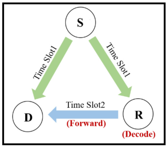
Figure 3.
The process of cooperative transmission in an indoor VLC system.
The structure diagram of the cooperative strategy based on space–time labeling diversity in indoor VLC system is illustrated in Figure 4. In this system, transmission of optical signal is in detail divided into two phases, that is, two time slots. During the first time slot, S transmits the modulated optical signal , R and D receive, then R decodes. During the second time slot, R forwards the modulated optical signal to D once binary information bits is decoded correctly in the first time slot at R. Otherwise, R does not participate in cooperation. D decodes data which are received during two time slots. The mapping of optical signals transmitted at S is shown in Figure 5, and the original constellation mapped at S is shown in Figure 6. Since the DF protocol is used in this paper, the decoding and recoding of original data transmitted from S are added at R. In a traditional cooperative VLC system, repetitive signals are only forwarded at R, and the gain of spatial coding cannot be maximized. However, the cooperative strategy proposed in this paper not only remaps optical signals but also introduces space–time labeling diversity to improve the reliability of the system. The mapping of optical signals transmitted at R is shown in Figure 7, and the original constellation mapped at R is shown in Figure 8. In Figure 5 and Figure 7, and are respectively the original constellation at S and R. The original data are passed through two mappers to produce optical signals and .
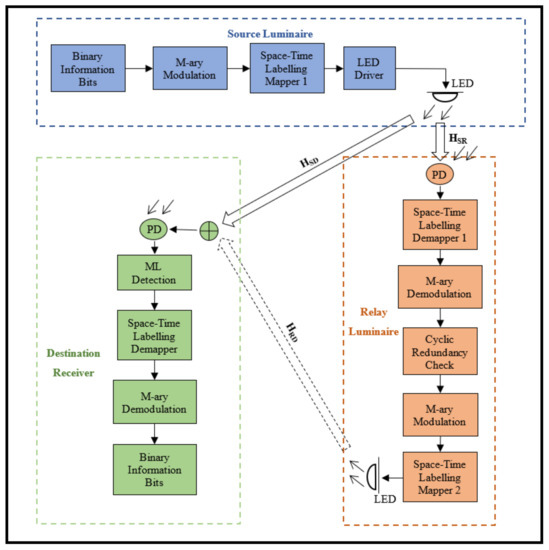
Figure 4.
The structure diagram of the cooperative strategy based on space–time labeling diversity in an indoor VLC system.
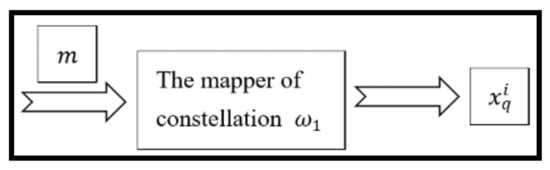
Figure 5.
The mapping of optical signals transmitted at source luminaire (S).
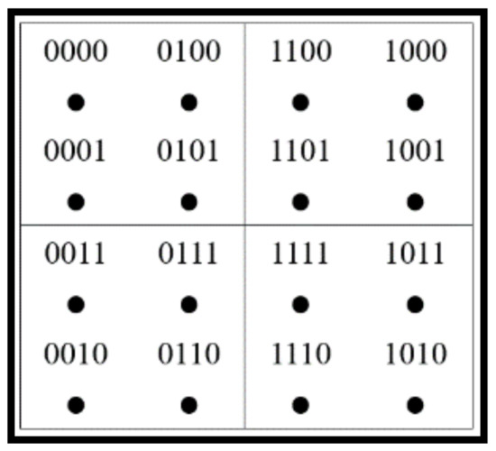
Figure 6.
The original constellation mapped at S.
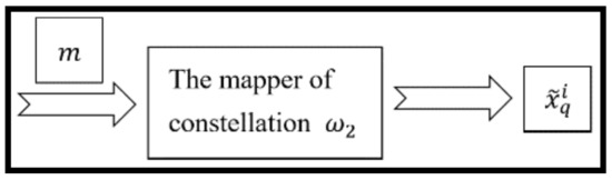
Figure 7.
The mapping of optical signals transmitted at relay luminaire (R).
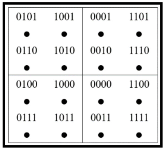
Figure 8.
The original constellation mapped at R.
During the first time slot, the received signals are,
where is the signal transmitted from S, is the transmitting power at S, is the average power of signal at S, and are the channel fading coefficients of S to R and S to D, and and are additive Gaussian white noises received by R and D during the first time slot. During the second time slot, the received signals are,
where is the signal forwarded from R, is the transmitting power at R, is the average power of the signal at R, is the channel fading coefficient of R to D, is the additive Gaussian white noise received by D during the second time slot.
3.3. Theoretical Analysis of Performance of the Proposed Cooperative Strategy
It is assumed the D is fully aware of the channel state information of all transmission links, and MRC is employed to detect signals at D. When R detects signals transmitted from S,
where is signal detected by R from S. According to the detection result of signal transmitted by S at R, there are two cases as follows.
(1) When R decodes incorrectly, D will detect signals transmitted by S during the first time slot. The ML detection at D is
where is signal detected by D from S.
(2) When R decodes correctly, R forwards signals transmitted from S, D will detect the combined signals from S during the first time slot and from R during the second time slot. The ML detection at D is
where is signal detected by D from S and R. The total bit error ratio (BER) can be derived from the model of the three-terminal cooperative indoor VLC system and the principle of the DF protocol,
where is the BER between S and R, is the BER between S and D, and is the joint BER between S and R and between S and D. The N–N nearest neighbor method is adopted in this paper to investigate BER performance; that is, the error probability of transmitting a symbol is related to Euclidean distance. The shorter the distance between two terminals, the greater error probability. Therefore, only terminals with the shortest distance are considered. It can be derived from Equations (15) and (17) that when R decodes incorrectly, that is, when S transmits and R decodes it to , the probability of incorrectly decoding at R is
where is a given value. It can be further transformed with the help of the definition of the function, where BER between S and R is
where , , is the number of iterations. Similarly, BER between S and D is
In space–time labeling diversity, received signals are remapped at R, but modulation of signals at S will not be changed, so performance of cooperative communication system mainly depends on . It can be derived from Equation (15), Equation (16), Equation (18), and Equation (19) that the probability of incorrectly decoding at D when correctly decoding at R is
where , . It can be further transformed with the help of the definition of the function, where the joint BER between S and R and between S and D is
where , , . In Figure 6, taking the points of 1111 and 1110 on the constellation for example, the distance between them is 2, while the distance is 4 in Figure 8. Therefore, the distance product of the proposed scheme is , while in the scheme with amplify and forward (AF), the constellation at R is the same as that at S, the distances are both 2, and the distance product is . It can be summarized that the distance product in the proposed scheme has been expanded by 4 times, which is equal to gaining 4 times the channel between S and R.
4. Results and Analyses
In this section, we present simulation results of performance of cooperative space–time labeling diversity for indoor VLC systems. The Monte Carlo simulation was adopted. We assume three terminals were set to be distributed inside a study room with dimensions of , which were S, R, and D. The central coordinate of the ground was (0, 0, 0). We considered the 4-QAM and DF protocols. All terminals had only one LED, whose transmitting power was 2 W. The channels of S to R, R to D, and S to D were all additive Gaussian White noise channels, and the channel variance between S and D was 1, S and R was 10, R and D was 1. Other parameters for the simulation are listed in Table 1.

Table 1.
Parameters for the simulation.
4.1. Simulation of Channel Correlation of the Transmit Domain
In Section 3, it was mentioned that S selects R as a partner according to the channel correlation coefficient of the transmitting domain between S and R. The channel correlation of the transmitting domain is defined as the channel correlation from different LEDs to the same photodetector. The influence of the distance between S and R on channel correlation of the transmitting domain was measured and the curve is shown in Figure 9. It was assumed that S and D were fixed in position in the space. R was moved to obtain different values of distance between S and R. It can be seen that channel correlation of the transmitting domain decreased when the distance between S and R increased. When the distance was less than 50 cm, the channel correlation was larger, which exactly matched the fact that channel correlation of MIMO is great due to the short distance between LEDs, generally below 50 cm. When the distance was more than 50 cm, the channel correlation gradually became weaker. Therefore, R whose distance is greater than 50 cm from S will be a good choice as a partner for S.
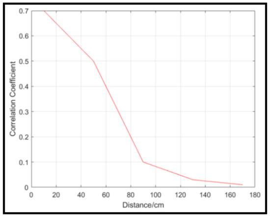
Figure 9.
The relationship between the channel correlation of the transmitting domain and the distance between S and R.
Furthermore, we also measured the influence of the distance between R and D on the channel correlation of the transmitting domain. It was assumed that S and D were fixed in position in the space. R was moved to obtain different values of distance between R and D. A surprising result is shown in Figure 10. Unlike the curve in Figure 9, as the distance between R and D increased, the channel correlation coefficient also increased, and the value of the coefficient changed in a small range. When the distance between R and D was 300 cm, the value was 0.2, and the channel correlation was not too large. The distance between R and D has only a limited impact on the channel correlation of the transmitting domain.
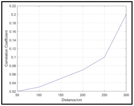
Figure 10.
The relationship between the channel correlation of the transmitting domain and distance between R and D.
4.2. Comparison of Theoretical Derivation and Experimental Simulation
In order to verify the derived theoretical result of BER, we compared the derived theoretical BER curve and the simulation curve. It was assumed that S and R both have the same average power. D was fully aware of the channel state information of all the transmission links. In Figure 11, the red curve is drawn according to Equation (25), while the blue one is the simulation result. It can be seen that as the SNR of the channel between S and R rise, the two curves approximately coincide and both meet the lower bound, which proves that the derived formula of the joint BER and simulation algorithm are both correct.
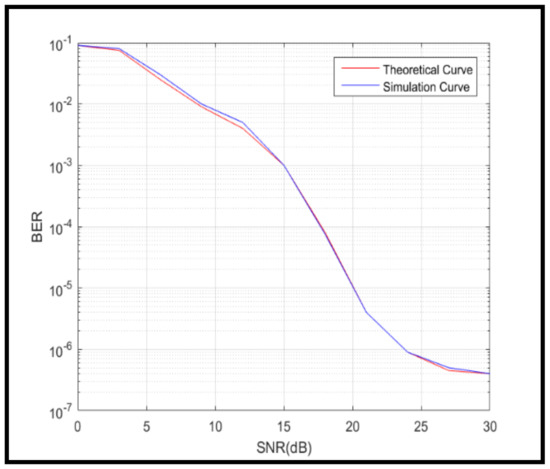
Figure 11.
Comparison of the theoretical derivation and simulation.
4.3. Comparison of the Proposed Cooperative Scheme and Conventional Cooperative Schemes
In most cooperative schemes for VLC systems, only AF or DF are employed at R. In Figure 12, we compared BER performance of different schemes in cooperative indoor VLC systems, which were a cooperative space–time labeling diversity (CSTLD) scheme, a DF scheme, and a AF scheme. In the DF scheme and the AF scheme, R only employed the DF protocol or AF protocol to forward, while in CSTLD scheme, besides the DF protocol adopted at R, the space–time labeling diversity structure was designed for S and R. It can be seen that the CSTLD scheme had an outstanding performance over the other two schemes, especially when SNR was below 15 dB. In the AF scheme, the noise was amplified with the received signal at R, which increased the difficulty of detection at D when SNR was low, especially below 12 dB. In the DF scheme, low SNR caused a decrease in successful decoding at R. In the CSTLD scheme, though the DF protocol was also adopted at R, the structure of the space–time labeling diversity greatly improved the ability to detect a signal at D. The BER performances of the three schemes tended to be consistent when the SNR was above 24 dB. These facts mean that the CSTLD scheme may be more robust when the channel condition is poor.
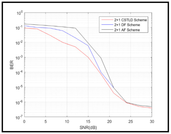
Figure 12.
Comparison of the proposed scheme and the conventional schemes.
4.4. Comparison of the Proposed Cooperative Scheme and the MIMO scheme
In cooperative schemes, relay luminaires were introduced to set up the structure of the virtual MIMO. The BER performances of the proposed cooperative scheme, the MIMO scheme, and the non-cooperative (NC) scheme are illustrated in Figure 13. Because the cooperative indoor VLC system was analyzed in this paper, the multiple input single output (MISO) indoor VLC system was compared. It can be seen that NC scheme obviously performed worse than the other two schemes. This demonstrated that cooperative transmission plays an important role. In the MISO scheme, gain of spatial diversity was obtained due to cooperation of R, so it had a great improvement of BER performance compared to the NC scheme. However, the values of BER of the MISO scheme and the NC scheme both remained high when the SNR was below 12 dB and 15 dB, respectively. This was mainly due to the introduction of space–time labeling diversity, which can produce a gain of spatial diversity and a gain of coding.
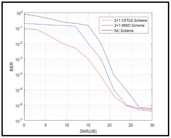
Figure 13.
Comparison of the proposed scheme and the multiple input multiple output (MIMO) scheme.
4.5. Influence of Modulation Order on The Proposed Cooperative Scheme
In Figure 11, Figure 12 and Figure 13, 4-QAM was employed to modulate binary bits, and the influence of the different modulation orders on the proposed cooperative scheme in the indoor VLC system is illustrated in Figure 14. It can be seen that BER performance was improved in the four schemes with different modulation orders, which were 2-PSK CSTLD, 4-QAM CSTLD, 8-QAM CSTLD, and 16-QAM CSTLD. However, subtle differences were still obtained. The 2-PSK CSTLD scheme performed the best of all. In the 2-PSK CSTLD scheme, one bit was transmitted during every time slot, which obviously caused a decrease in the transmission rate in the indoor VLC system. However, in some cases, it may be worthwhile to improve BER performance of system at the expense of decreased transmission rate. At the same time, the demodulation complexity at D can be reduced.
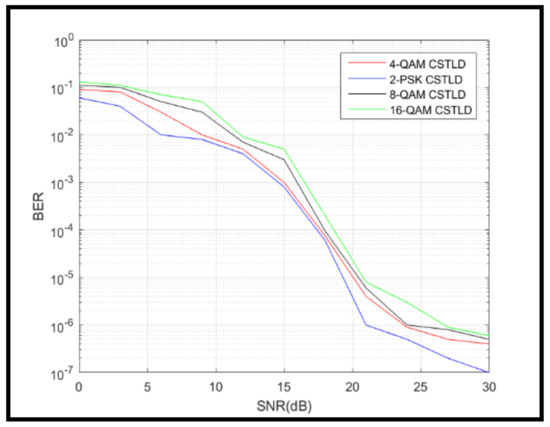
Figure 14.
Bit error ratio (BER) performance of different modulation orders for the proposed scheme.
5. Conclusions
In this paper, cooperative communication and space–time labeling diversity were first investigated, then the cooperative indoor VLC system with luminaires was set up and a cooperative strategy based on space–time labeling diversity was put forward to achieve high reliability of the system. Even though the complexity, cost, and power consumption of the proposed scheme are slightly greater than in the MIMO VLC system, the simulation results showed that it can significantly reduce BER. It performed better than the conventional AF scheme or DF scheme in the cooperative indoor VLC system. It is superior to the MIMO and non-cooperation VLC systems in terms of anti-channel correlation. This proposed scheme can be used for indoor VLC systems according to demand. All authors have read and agreed to the published version of the manuscript.
Author Contributions
This research article contains three authors, including J.-J.B., who graduated from Communication and Information Systems and was responsible for conceiving and designing the proposed algorithm, doing the experiments, and writing the paper and the replies. Q.M. analyzed the data, collected related literatures, and assisted in deriving formulas and simulation during revision with J.-J.B. J.-F.T. proposed many helpful suggestions on the conception, format, and writing of this paper. With the author’s help, this study was completed as scheduled. All authors have read and agreed to the published version of the manuscript.
Funding
This research was funded by the Social Science and Technology Development of Dongguan Science and Technology Bureau, grant number 2019507156746, the Research Fund Project of Dongguan Polytechnic, grant number 2019a15, the Science and Technology Innovation Strategy Special Fund Project of Guangdong Province, grant number pdjh2020b1266, pdjh2020b1260, and the Higher Vocational Education Brand Professional Construction Project of Guangdong Province, grant number 520901.
Conflicts of Interest
The authors declare no conflict of interest.
References
- Elgala, H.; Mesleh, R.; Haas, H. Indoor Optical Wireless Communication: Potential and State-of-Art. IEEE Commun. Mag. 2011, 49, 56–62. [Google Scholar] [CrossRef]
- Grubor, J.; Randel, S.; Langer, K.D. Broadband Information Broadcasting Using LED-Based Interior Lighting. J. Lightwave Technol. 2008, 26, 3883–3892. [Google Scholar] [CrossRef]
- Mesleh, R.; Mehmood, R.; Elgala, H.; Hass, H. Indoor MIMO Optical Wireless Communication Using Spatial Modulation. In Proceedings of the 2010 IEEE International Conference on Communications, Cape Town, South Africa, 23–27 May 2010; pp. 1–5. [Google Scholar]
- Qiu, L.; Jiang, M. A Generalized Spatial Modulation for Indoor Optical Wireless Communications. In Proceedings of the 2015 IEEE Opto-electronics and Communications Conference, Shanghai, China, 2–28 July 2015; pp. 1–3. [Google Scholar]
- Nguyen, N.T.; Nguyen, Q.T.; Nguyen, N.H. The Index-based Optical Spatial Modulation Scheme in Optical MIMO. In Proceedings of the 2016 IEEE International Conference on Advanced Technologies for Communications, Hanoi, Vietnam, 12–14 October 2016; pp. 191–196. [Google Scholar]
- Xu, K.; Yu, H.; Zhu, Y.J. Channel-adapted Spatial Modulation for Massive MIMO Visible Light Communications. IEEE Photonics Technol. Lett. 2016, 28, 2693–2696. [Google Scholar] [CrossRef]
- Bing’an, R.; Zhiqun, B.; Yingchao, Y.; Ke, P.; Shangqian, S.; Tao, H.; Kyungsup, K. A Novel SM-based Indoor VLC System with Index Modulation. In Proceedings of the 2018 IEEE 18th International Conference on Communication Technology, Chongqing, China, 8–11 October 2018; pp. 16–20. [Google Scholar]
- Zhu, Y.J.; Liang, W.F.; Zhang, J.K.; Zhang, Y.Y. Space-Collaborative Constellation Designs for MIMO Indoor Visible Light Communications. IEEE Photonics Technol. Lett. 2015, 27, 1667–1670. [Google Scholar]
- Palitharathna, U.G.R.K.W.S.; Samarasinghe, A.G.D.U.K.; Wijayarathna, Y.M.L.D.; Suraweera, S.A.H.A.; Godaliyadda, G.M.R.I. Spatial Modulation for Indoor MIMO Visible Light Communication System; Sri Lanka (IESL) Transactions Part B; The Institution of Engineers: Colombo, Sri Lanka, 2017; pp. 391–399. [Google Scholar]
- Bing’an, R.; Zhiquan, B.; Yingchao, Y.; Ke, P.; Shangqian, S.; Tao, H.; Kyungsup, K. Enhanced Performance of Indoor Cooperative IHDAF Protocol Based SM VLC System. In Proceedings of the 2018 18th IEEE International Conference on Communication Technology, Chongqing, China, 8–11 October 2018; pp. 326–330. [Google Scholar]
- Gabriela, A.R.; Kyuntak, K.; Kyujin, L.; Kyesan, L. Performance Analysis of SFBC-FSTD in Multiple-input Single-output-VLC Systems with Co-Channel Interference. IET Optoelectron. 2018, 12, 106–113. [Google Scholar]
- Sendonaris, A.; Erkip, E.; Aazhang, B. User Cooperation Diversity-Part I: System Description. IEEE Trans. Commun. 2003, 51, 1927–1938. [Google Scholar] [CrossRef]
- Hongjun, X.; Govindasamy, K.; Narushan, P. Uncoded space-time labelling diversity. IEEE Commun. Lett. 2016, 20, 1511–1514. [Google Scholar]
© 2020 by the authors. Licensee MDPI, Basel, Switzerland. This article is an open access article distributed under the terms and conditions of the Creative Commons Attribution (CC BY) license (http://creativecommons.org/licenses/by/4.0/).