Article

Substructure-Based Topology Optimization for Symmetric Hierarchical Lattice Structures

1
Hubei Key Laboratory of Digital Textile Equipment, Wuhan Textile University, Wuhan 430073, China
2
School of Artificial Intelligence and Automation, Huazhong University of Science and Technology, Wuhan 430074, China
*
Author to whom correspondence should be addressed.
Symmetry 2020, 12(4), 678; https://doi.org/10.3390/sym12040678
Submission received: 6 March 2020 / Revised: 9 April 2020 / Accepted: 9 April 2020 / Published: 24 April 2020

Abstract

:
This work presents a topology optimization method for symmetric hierarchical lattice structures with substructuring. In this method, we define two types of symmetric lattice substructures, each of which contains many finite elements. By controlling the materials distribution of these elements, the configuration of substructure can be changed. And then each substructure is condensed into a super-element. A surrogate model based on a series of super-elements can be built using the cubic B-spline interpolation. Here, the relative density of substructure is set as the design variable. The optimality criteria method is used for the updating of design variables on two scales. In the process of topology optimization, the symmetry of microstructure is determined by self-defined microstructure configuration, while the symmetry of macro structure is determined by boundary conditions. In this proposed method, because of the educing number of degree of freedoms on macrostructure, the proposed method has high efficiency in optimization. Numerical examples show that both the size and the number of substructures have essential influences on macro structure, indicating the effectiveness of the presented method.

1. Introduction

Symmetrical structure is a kind of widely used structure. In topology optimization [1,2], the structure is designed according to symmetry, so as to realize the multi-functional design of macro structure [3,4,5]. The symmetrical structure is more suitable for manufacturing. It is helpful to avoid the problem of low manufacturability caused by the homogenization method [6].
Because of its scale separation assumption [7,8], the material is often unconnected in the multiscale structure [9,10], and the designed structures are not manufacturable in practices using this method. Moreover, due to the large overhang hand angle and length [11,12,13], the optimized configuration only exists in theory. To overcome the barrier between topology optimization and manufacturing, many scholars try to find the topology optimization method of integrated manufacturing. Osanov et al. [14] discussed the manufacturability of multiscale designs and presented the fundamental findings for designing the periodic structure. Wang et al. [15] presented an optimization method for the cellular lattice structure based on the shape metamorphosis, and this optimized structure can be fabricated in additive manufacturing. Based on the thermal conductivity of lattice structure, Cheng et al. [4] proposed a concurrent optimization method based on the boundary conditions to optimize the lattice infill and design-dependent movable features. To verify the accuracy and efficiency of the optimization method, Wang et al. [16] presented a periodic lattice optimization method using Isogeometric analysis.
Based on the symmetry of microstructure, most of works tackled the design method to optimize the two scales structure. In order to ensure the material connectivity among microstructures, the shape geometries or physical responses interpolation method has been adopted to design the macro/micro structures [17,18]. To interpolate a prototype microstructure and obtain a family of graded connectable microstructures, Wang et al. [19] proposed a shape metamorphosis technology to design the multiscale structure. Based on the homogenization method, Groen and Sigmund [20] presented an advanced projection scheme to achieve high-resolution and connectable microstructures. To validate the accuracy of the asymptotic homogenization method, Arabnejad et al. [21] determined the effective elastic moduli and yield strength of six lattice structures to optimize the multiscale structure. In order to further extend the design space, Li et al. [22] presented a special composite structure with microstructures of identical topology with different length/width ratios. Considering the adjacent cellular materials, Radman et al. [23] proposed a progressive design strategy to design the cellular materials using the globally filtered sensitivities.
This paper presents a topology optimization design method for symmetric structures based on substructure. According to the static condensation [24,25] or domain decomposition [26], the substructure-based method is suitable for the large-scale computing of structural topology optimization. In the calculation of the condensed stiffness matrix, the calculation efficiency can be doubled due to the symmetry of this stiffness matrix [27,28]. In this paper, we also design two types of microstructures with symmetry. It should be noted that the symmetry of the condensed stiffness matrix is not related to the symmetry of microstructure.
The structure and content of this paper is organized as follows. The static condensation of the substructure is described in detail in Section 2, the construction method for the substructure based symmetric microstructure is elaborated in Section 3, and the topology optimization model and the sensitivity analysis for this proposed topology optimization method is expressed in Section 4. To demonstrate the capability of the proposed method, three numerical examples are presented in Section 5. Finally, a summary of some open problems related to this paper is discussed in Section 6.

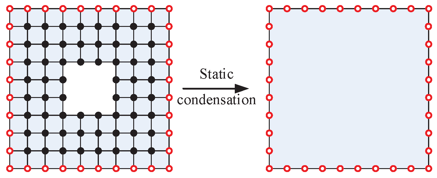
2. The Static Condensation of Substructure

In the finite element method, the finite mesh in any region can be condensed into a super-element shown in Figure 1. And the strain and stress fields of its internal nodes can be represented by their boundary nodes [27,28].
Here, based on the internal and boundary modes, the equilibrium equation of a substructure can be established as follows:
KU = [ K mm K m s K s m K ss ] [ U m U s ] = [ F m F s ]
where K m m and K s s are the stiffness matrix of the boundary and internal nodes, respectively. K sm , K ms are the coupling sub-stiffness matrixes. U m and U s are the response sub-vector of the nodes.
Here, applying the Guyan method [24] the displacement vector can be expressed as follows:
U = [ U m U s ] = [ I T ] U m = T * U m
where U s = T U m .
Substituting Equation (2) into Equation (1), the first row of Equation (1) yields the following:
| K mm K ms K s s 1 K sm | U m = F m K ms K s s 1 F s .  
Substituting Equation (5) into Equations (2) and (3), the condensed stiffness matrix can be obtained,
K * = K mm K sm T K ss 1 K sm ,
Because only boundary nodes are reserved, the size of the condensed matrix is much smaller than the original matrix.

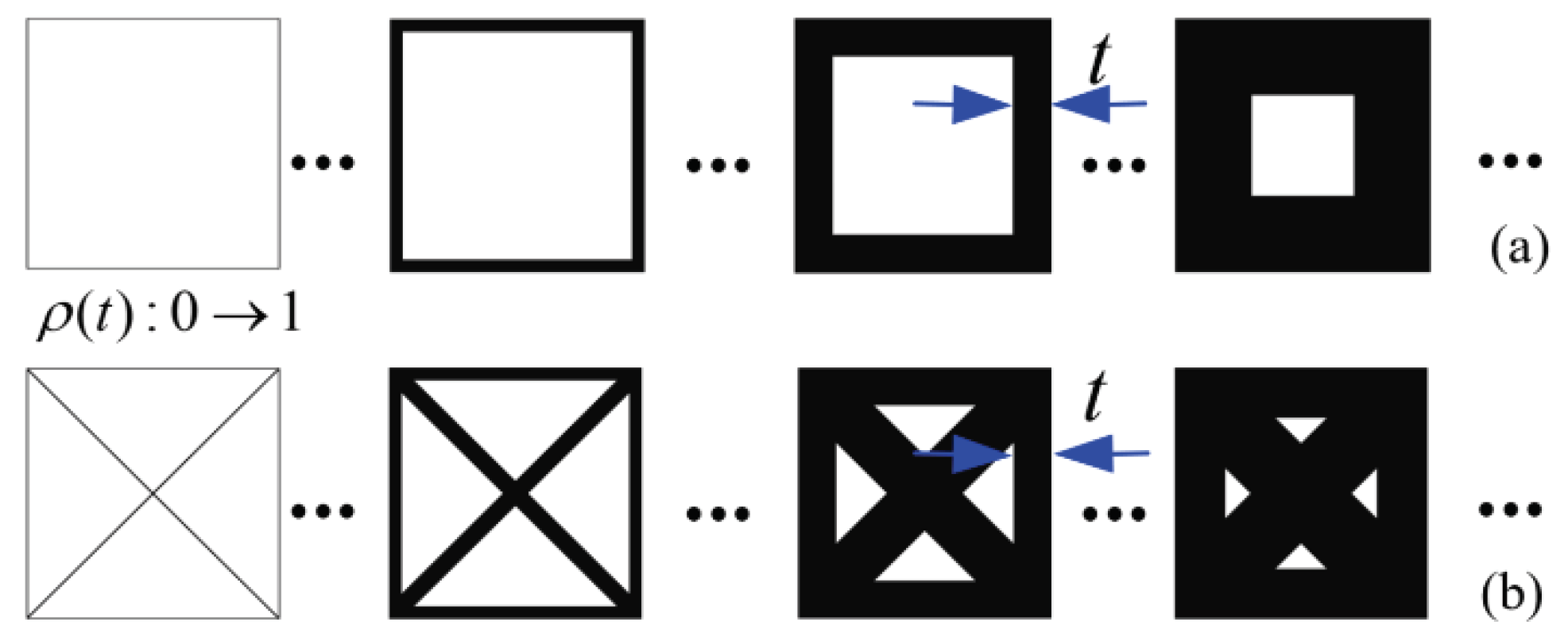
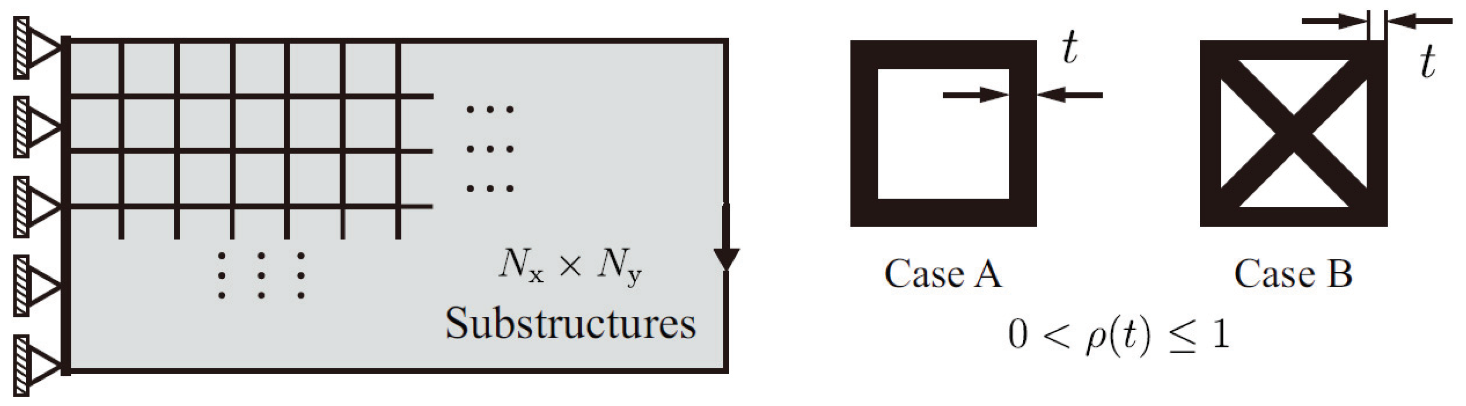
3. Substructure-Based Symmetric Microstructure Model

In order to construct the stiffness with different densities, a series of condensed substructures with a similar configuration for sampling densities using the finite element method shown in Figure 2 are considered. The density of the associated substructure is controlled by the parameter t . Here, the self-defined substructure only contains two types of material: full of materials or void materials. In the process of the proposed optimization method, the more elements of the substructure, the larger the stiffness matrix of the corresponding surrogate model, and the longer the optimization iteration time. Considering the efficiency of iterative calculation, we fix the number of elements of substructure here [29,30]. Considering the computation efficiency, all substructures are discretized into 100 × 100 square bilinear elements.
Here, each substructure has the same boundary nodes. According to Equation (4), we consider the constructed a series of condensed stiffness matrices K * for R sampling densities [ k 1 * ( ρ 1 ) , , k R * ( ρ r ) ] , 0 < ρ i 1 , i = 1 , , R . For the convenience of calculation, each condensed stiffness matrix is restored in a column vector of length N2 attributed. Here, we assume that a condensed stiffness matrix at any density can be expressed as follows:
k * ( ρ i ) i = 1 x α i ( ρ i ) k i ,
where coefficients α i ( ρ i ) are scale functions of density ρ . K * ( ρ i ) can be expressed in matrix form:
K * ( ρ i ) α 1 ( ρ i ) [ k 1 ] + α 2 ( ρ i ) [ k 2 ] + + α x ( ρ i ) [ k x ] .
According to symmetry, each element in a matrix can be written as follows:
K * ( ρ i ) = ( K * ( ρ i ) ) T   .
The coefficient can be obtained using use cubic spline interpolation method:
K a , b ( ρ k ) = f ( ρ k ) = c 3 ρ k 3 + c 2 ρ k 2 + c ρ k + c 0 , 0 ρ k 1 , a b ,
where f ( 0 ) = f ( 1 ) = 0 , f ( ρ i ) = K i * , f ( ρ i + 1 ) = K i + 1 * , f ( ρ i ) = f ( ρ i + 1 ) and f ( ρ i ) = f ( ρ i + 1 ) .
The condensed stiffness matrix K * ( ρ i ) can be reconstructed explicitly,
K * ( ρ i ) = α ˜   K ˜   α ˜ 1 ( ρ i ) [ k 1 ] +   α ˜ 2 ( ρ i ) [ k 2 ] + +   α ˜ z ( ρ i ) [ k z ]
Here, we consider a generalized model for substructure stiffness augmented with a penalized density:
K * : = ρ 1 + p ( 1 ρ ) K * ( ρ ) ρ 1 + p ( 1 ρ ) i = 1 x   α ˜ i ( ρ ) [ k i ] .
In the proposed model for minimizing the compliance of structure, the penalty factor p≥1 means that the associated matrix with intermediate densities is penalized.

4. Symmetric Structures Design Method

4.1. The Topology Optimization Model

Find : X ( ρ ) min : c ( ρ ) = U T K U s . t . K U = F V υ ρ i [ 0 , 1 ] , i = 1 , , n
According to Equation (10), the global stiffness matrix can be re-expressed as follows:
K = j = 1 s u b ρ j 1 + p ( 1 ρ j ) K * ( ρ j ) j = 1 s u b ρ j 1 + p ( 1 ρ j ) i = 1 z α ˜ i ( ρ j ) [ K i ] .

4.2. Sensitivity Analysis

The Derivative of the Objective and Constraint with Respect to the Densities ρ i can be obtained,
c ( ρ ) ρ i = i = 1 N U T K i * U ρ = U T i = 1 N K i * ρ i U .
Based on Equation (12), Κ * / ρ j can be obtained as follows:
K i * ρ j = ( p 1 ) ρ j ( p 2 ) K i * ( ρ j ) + ρ i ( p 1 ) K i * ( ρ j ) ρ i = ( p 1 ) ρ j K i * + ρ j ( p 1 ) s = 1 m α s ( ρ j ) ρ j [ k s ] .
Here, to update the density design variables [30], we choose the optimality criteria (OC) as the optimality criteria:
ρ i n e w = { max ( ρ min , ρ i ε ) if ρ i D i η max ( ρ min , ρ i ε ) ρ i D i η if max ( ρ min , ρ i ε ) ρ i D i η min ( 1 , ρ i + ε ) . min ( 1 , ρ i + ε ) if min ( 1 , ρ i + ε ) ρ i D i η
And the parameter D i can be found as follows:
D i = c ρ i / κ V ρ i ,
where the κ is Lagrange multiplier. V / ρ i = v i is the volume of i-th substructure, which is an constant value in the SIMP method. c / ρ i is the sensitivity number given in the Equation (13).
In this paper, we assume that the design result is the optimal structure when the difference objective function value between two iterations is less than 10−3.

5. Numerical Example

Here, we set the Young’s modulus to E=1, and the Poisson’s coefficient to 0.3 in our given examples.

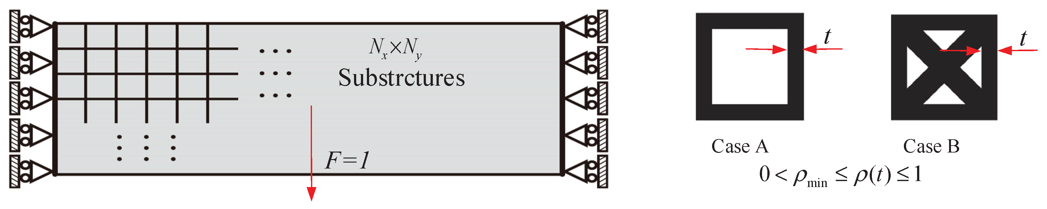
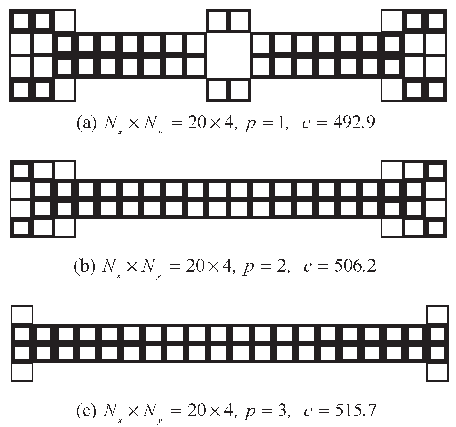
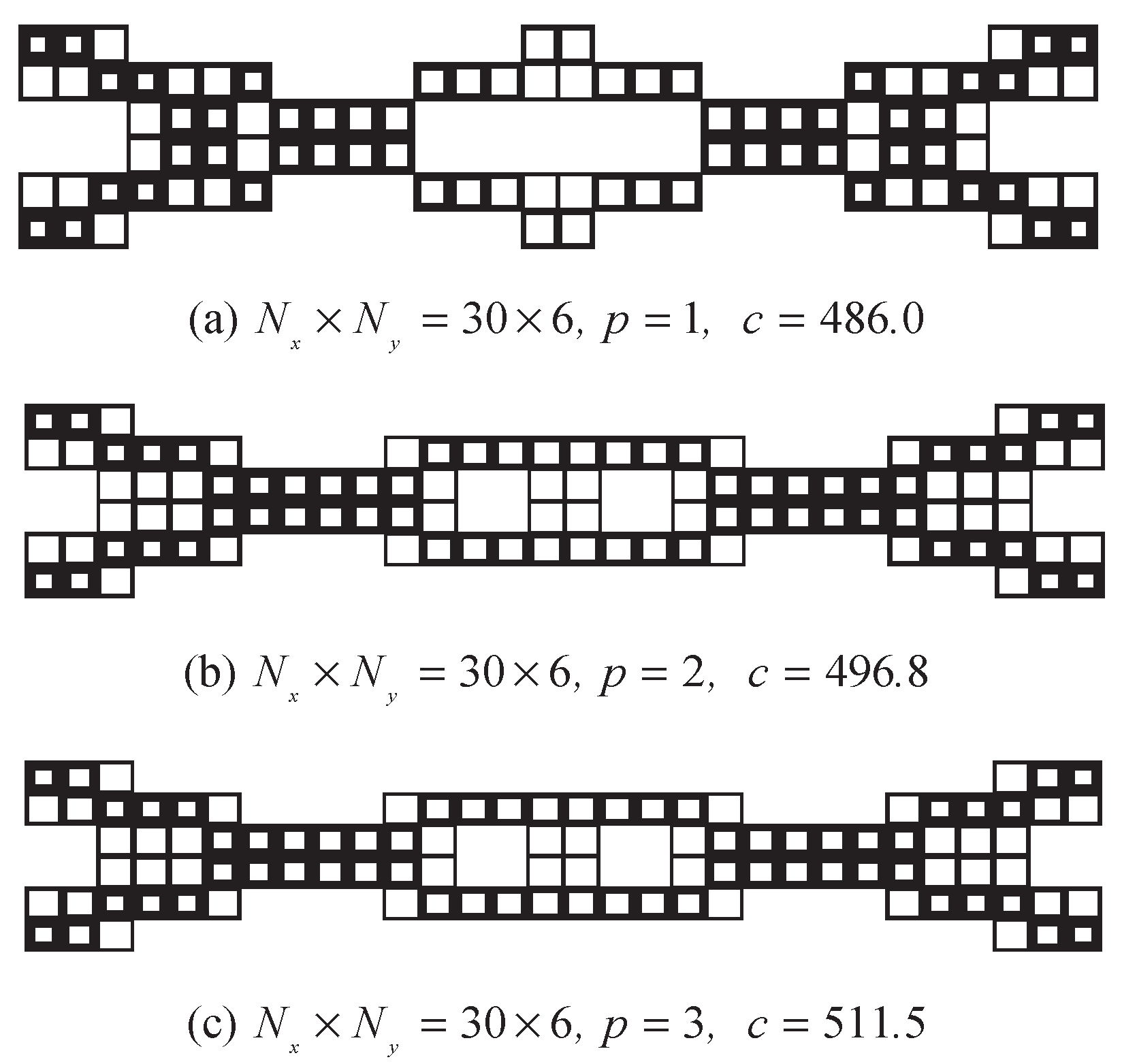
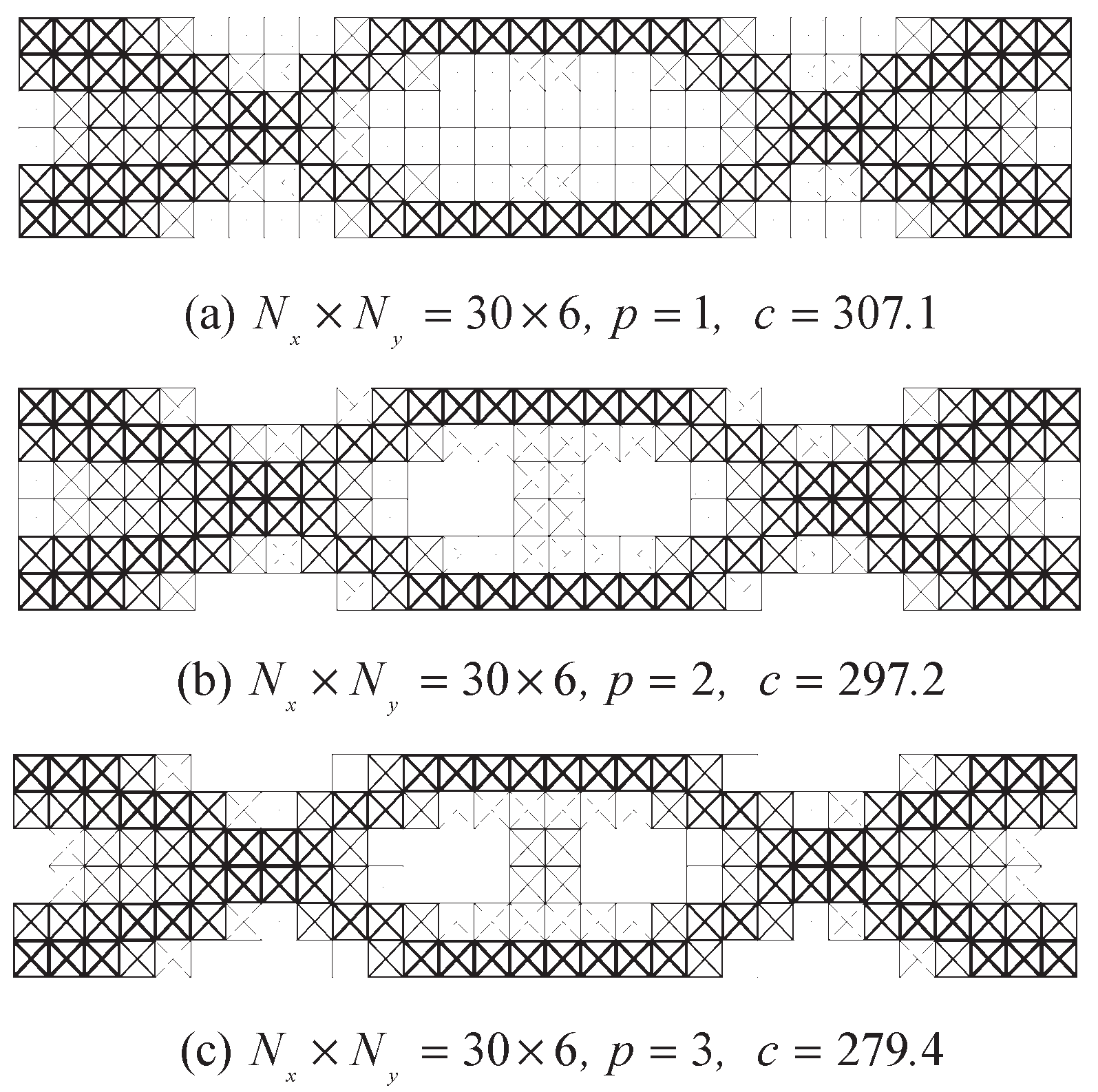
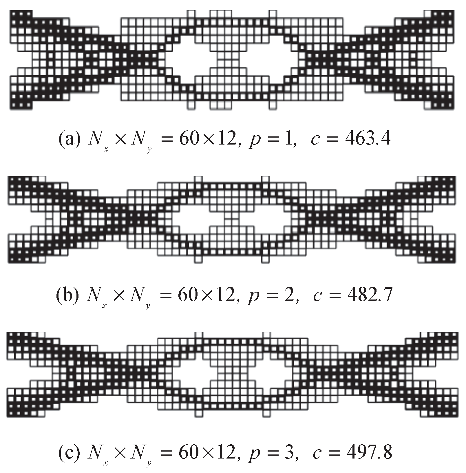
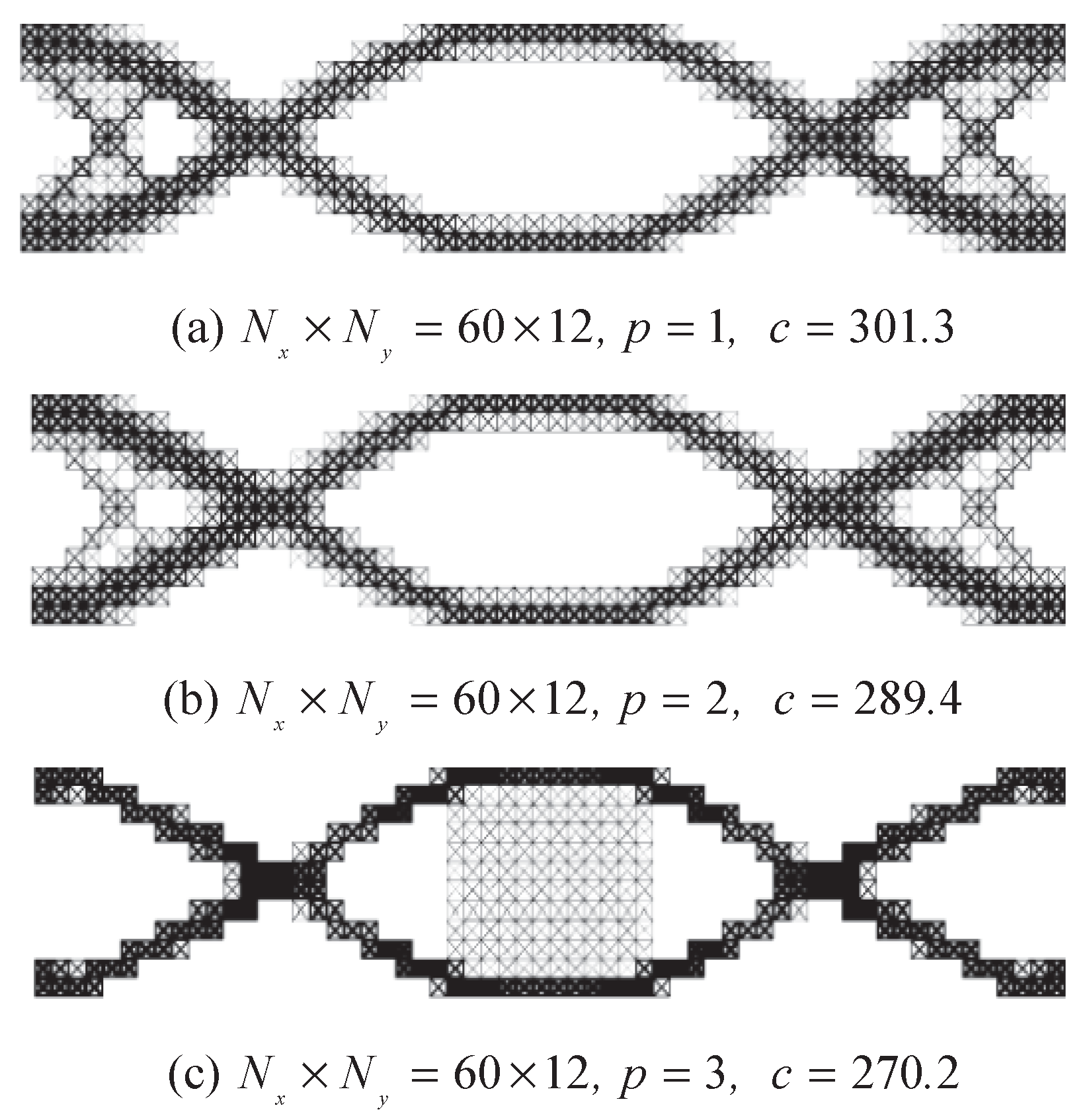
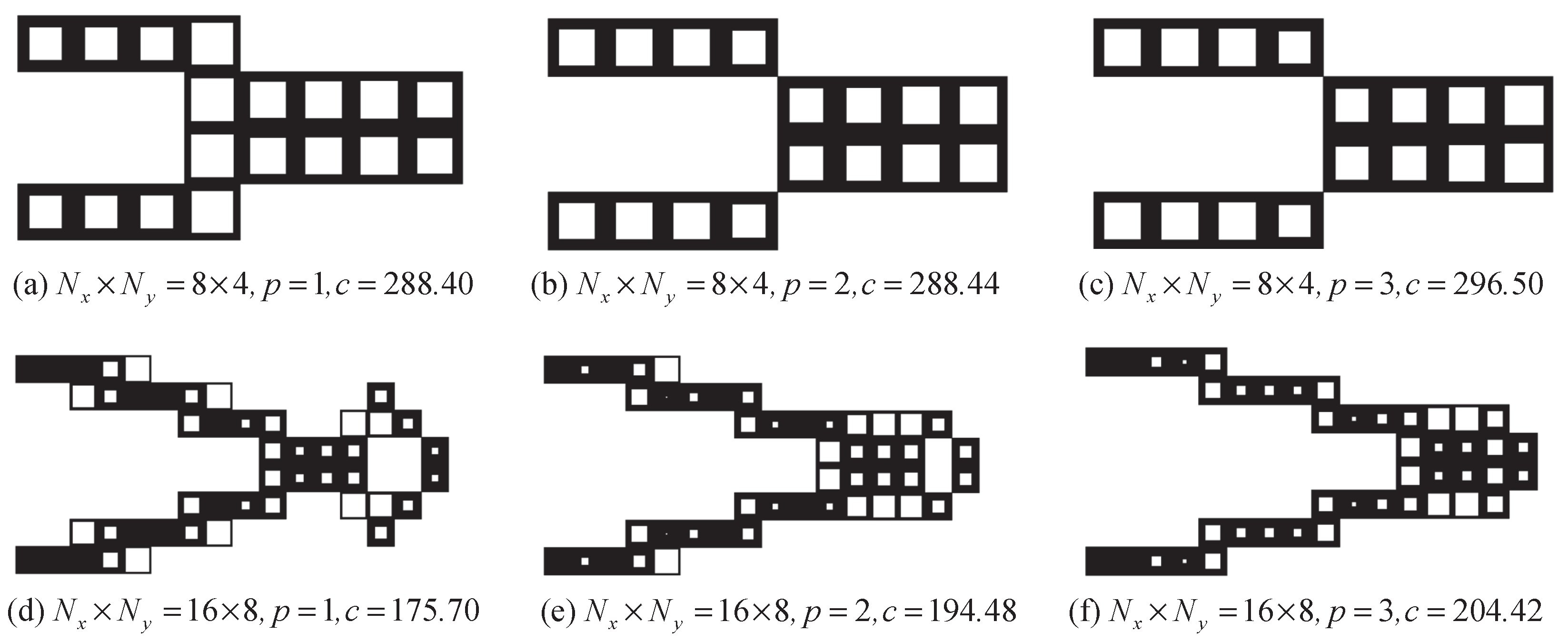
5.1. Clamped Ends Beam

The design domain of the problem is a rectangle of size 5 m × 1 m that fixed at both sides, as shown in Figure 3. A load F=1 is placed at the center. The volume fraction of solid material to be preserved is set to 30%.
In this design example, three discretization resolutions are considered to divide the whole design domain: N x × N y = 20 × 4 , N x × N y = 30 × 6 and N x × N y = 60 × 12 . in the process of topology optimization, the filer radiuses are set as 1.1 times of the substructure length. To avoid the checkerboard pattern issue, we consider the optimal configuration under different penalty factors 1, 2, and 3, respectively. The optimized results for the three discretization resolutions are shown in Figure 4, Figure 5, Figure 6, Figure 7, Figure 8 and Figure 9. From the optimal result, the following can be observed: (1) The optimization results are all symmetrical structures, independent of the discretization resolutions. (2) The symmetry of microstructure does not affect the symmetry of macrostructure. It can be observed that the compliance value of the design with case B lattice is lower than the design with Case A lattice. And this compliance value decrease with the increase in the number of substructures.

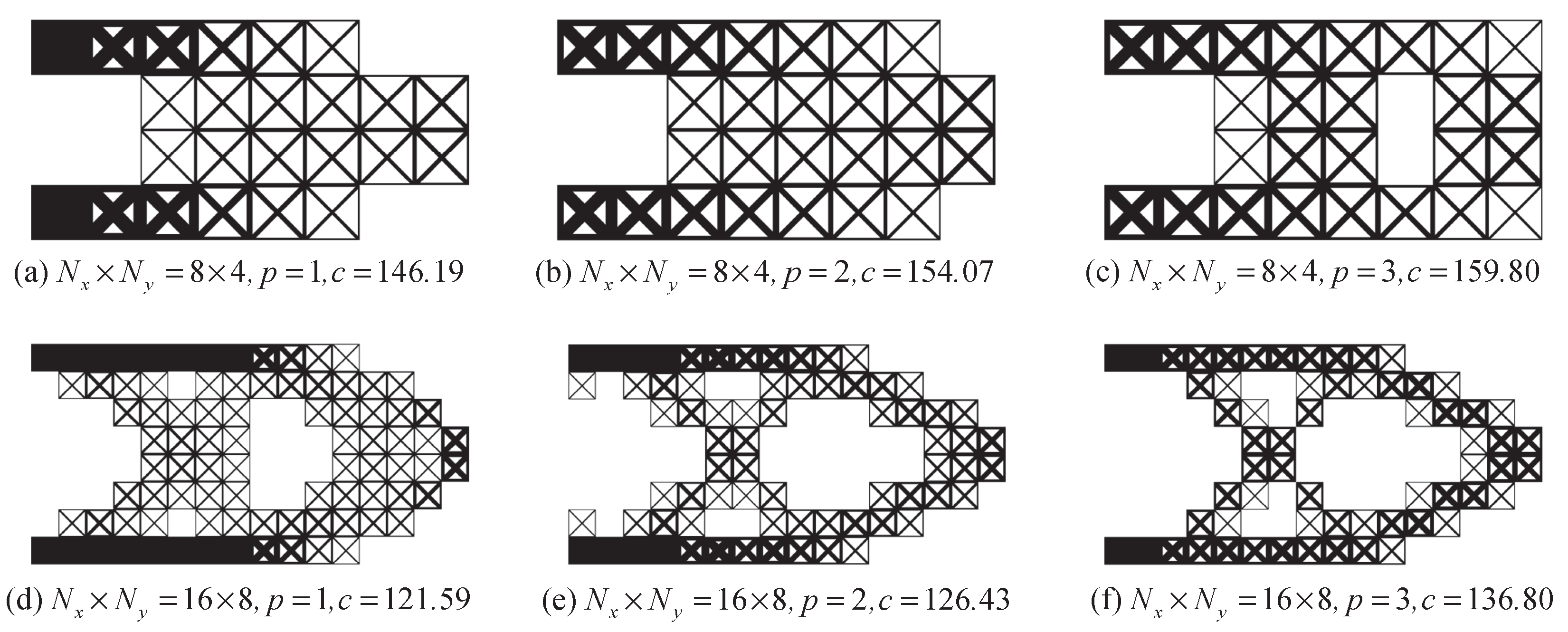
5.2. The Cantilever Design

The cantilever design problem is given in Figure 10. The ratio of the horizontal and vertical dimension of this design domain is 2. The left-end of the cantilever is clamped and a unit vertical load is applied on the middle point of the right edge. The volume fraction of solid material to be preserved is set as 0.4.
Here, the whole design domain is divided into N x × N y = 8 × 4 and N x × N y = 16 × 8 , respectively. The penalty is set to p = 1, 2, 3. The design results of the two resolutions for the two cases are shown in Figure 11 and Figure 12. It can be concluded that the compliance value increases when the penalty increasing. For the same discretization resolution, the objective function value with case A is larger than that of case B.

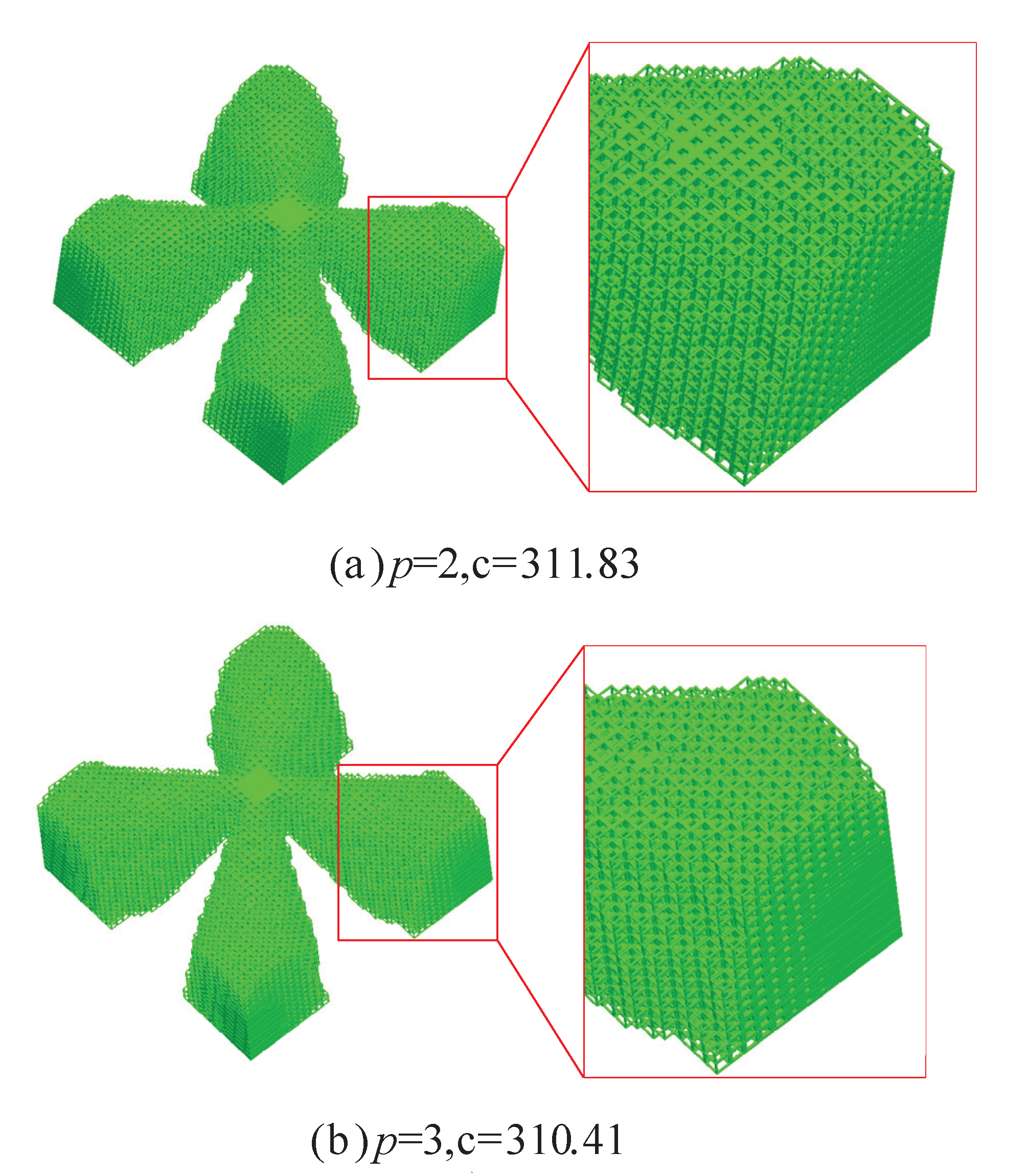
5.3. D Simply Supported Cube Design

In this example, a cube is clamped at four bottom corners. And the design domain is D = 1   m × 0.5   m × 1   m , as shown in Figure 13. A load is applied to the center of the top surface. Here, we set the volume faction as 30%. To improve the calculation efficiency, the substructure is discretized into 30 × 30 × 30 eight nodes cubic elements.
To simplify, the given design domain is only discretized into N x × N y × N z = 40 × 20 × 40 substructures. Due to the large number of intermediate density substructures, it is unnecessary to obtain the clarify structural pattern design. We design the structure with the penalty p = 2 and 3. Similar to the example, the filter radius is set as times of the substructure length. And the corresponding design results are summarized in Figure 14 and Figure 15. Form these results, the compliance value with case B is more likely to converge to compact topology pattern, and this value for the case A lattice substructure is a little smaller than case B with the same penalty factor. With an increasing penalty factor, the design becomes more compact with a clear structural pattern.
Here, we can conclude that the optimization results are symmetric as long as the boundary constraints are symmetric. And the layout of microstructure also has symmetry, which is consistent with that of the macrostructure.

6. Conclusions

In this paper, we present a substructure-based topology optimization for symmetric lattice structures with substructuring to minimize compliance of the multi-scale structure. Form the design result, all optimization design are symmetrical structures, which is unrelated to the discretization resolutions. Moreover, the symmetry of microstructure does not affect the symmetry of macrostructure. In our proposed method, the reconstruct stiffness matrix only calculates the element in one upper or lower triangle area using the cubic spline interpolation based on the symmetry of the stiffness matrix. Three numerical examples show that this proposed method for the reconstructing matrix can be applied to two- and three-dimensional topology optimization problems.

Author Contributions

Conceptualization, R.X.; methodology, Z.W.; software, Z.W.; writing—original draft preparation, Z.W.; writing—review and editing, Z.W.; supervision, R.X.; funding acquisition, R.X. All authors have read and agreed to the published version of the manuscript.

Funding

This research was funded by National Natural Science Foundation of China under grant number 51875220.

Acknowledgments

The authors acknowledged the editor and reviewers for their very insightful comments, which resulted in substantial improvements of our paper.

Conflicts of Interest

The authors declare that there are no conflicts of interest regarding the publication of this article

Abbreviations

SIMPSolid isotropic material with penalization
BESOBi-directional evolutionary structural optimization
MORModel Order Reduction
FEAFinite element analysis

References

  1. Xia, L.; Breitkopf, P. Concurrent topology optimization design of material and structure within FE2 nonlinear multiscale analysis framework. Comput. Methods Appl. Mech. Eng. 2014, 278, 524–542. [Google Scholar] [CrossRef]
  2. Sigmund, O.; Søndergaard Jensen, J. Systematic design of phononic band–gap materials and structures by topology optimization. Philos. Trans. R. Soc. Lond. Ser. A: Math. Phys. Eng. Sci. 2003, 361, 1001–1019. [Google Scholar] [CrossRef]
  3. Park, J.H.; Yang, S.H.; Lee, H.R.; Yu, C.B.; Pak, S.Y.; Oh, C.S.; Kang, Y.J.; Youn, J.R. Optimization of low frequency sound absorption by cell size control and multiscale poroacoustics modeling. J. Sound Vib. 2017, 397, 17–30. [Google Scholar] [CrossRef]
  4. Cheng, L.; Liu, J.; Liang, X.; To, A.C. Coupling lattice structure topology optimization with design-dependent feature evolution for additive manufactured heat conduction design. Comput. Methods Appl. Mech. Eng. 2018, 332, 408–439. [Google Scholar] [CrossRef]
  5. Wang, Y.; Arabnejad, S.; Tanzer, M.; Pasini, D. Hip implant design with three-dimensional porous architecture of optimized graded density. J. Mech. Des. 2018, 140, 111406. [Google Scholar] [CrossRef] [Green Version]
  6. Bendsøe, M.P.; Kikuchi, N. Generating optimal topologies in structural design using a homogenization method. Comput. Methods Appl. Mech. Eng. 1988, 71, 197–224. [Google Scholar] [CrossRef]
  7. Da, D.; Yvonnet, J.; Xia, L.; Le, M.V.; Li, G. Topology optimization of periodic lattice structures taking into account strain gradient. Comput. Struct. 2018, 210, 28–40. [Google Scholar] [CrossRef] [Green Version]
  8. Xia, L.; Breitkopf, P. Multiscale structural topology optimization with an approximate constitutive model for local material microstructure. Comput. Methods Appl. Mech. Eng. 2015, 286, 147–167. [Google Scholar] [CrossRef]
  9. Liu, S.; Li, Q.; Chen, W.; Tong, L.; Cheng, G. An identification method for enclosed voids restriction in manufacturability design for additive manufacturing structures. Front. Mech. Eng. 2015, 10, 126–137. [Google Scholar] [CrossRef]
  10. Geers MG, D.; Yvonnet, J. Multiscale modeling of microstructure–property relations. Mrs Bull. 2016, 41, 610–616. [Google Scholar] [CrossRef]
  11. Langelaar, M. Topology optimization of 3D self-supporting structures for additive manufacturing. Addit. Manuf. 2016, 12, 60–70. [Google Scholar] [CrossRef] [Green Version]
  12. Langelaar, M. An additive manufacturing filter for topology optimization of print-ready designs. Struct. Multidiscip. Optim. 2017, 55, 871–883. [Google Scholar] [CrossRef] [Green Version]
  13. Zhang, K.; Cheng, G.; Xu, L. Topology optimization considering overhang constraint in additive manufacturing. Comput. Struct. 2019, 212, 86–100. [Google Scholar] [CrossRef]
  14. Osanov, M.; Guest, J.K. Topology optimization for architected materials design. Annu. Rev. Mater. Res. 2016, 46, 211–233. [Google Scholar] [CrossRef]
  15. Wang, Y.; Zhang, L.; Daynes, S.; Zhang, H.; Feih, S.; Wang, M.Y. Design of graded lattice structure with optimized mesostructures for additive manufacturing. Mater. Des. 2018, 142, 114–123. [Google Scholar] [CrossRef]
  16. Wang, Y.; Xu, H.; Pasini, D. Multiscale isogeometric topology optimization for lattice materials. Comput. Methods Appl. Mech. Eng. 2017, 316, 568–585. [Google Scholar] [CrossRef] [Green Version]
  17. Cramer, A.; Challis, V.; Roberts, A. Microstructure interpolation for macroscopic design. Struct. Multidiscip. Optim. 2016, 53, 489–500. [Google Scholar] [CrossRef]
  18. Du, Z.; Kim, H. Multiscale design considering microstructure connectivity. In Proceedings of the 2018 AIAA/ASCE/AHS/ASC Structures, Structural Dynamics, and Materials Conference, Kissimmee, FL, USA, 8–12 January 2018. [Google Scholar]
  19. Wang, Y.; Chen, F.; Wang, M. Concurrent design with connectable graded microstructures. Comput. Methods Appl. Mech. Eng. 2017, 317, 84–101. [Google Scholar] [CrossRef]
  20. Groen, J.; Sigmund, O. Homogenization-based topology optimization for high-resolution manufacturable microstructures. Int. J. Numer. Methods Eng. 2018, 113, 1148–1163. [Google Scholar] [CrossRef] [Green Version]
  21. Arabnejad, S.; Pasini, D. Mechanical properties of lattice materials via asymptotic homogenization and comparison with alternative homogenization methods. Int. J. Mech. Sci. 2013, 77, 249–262. [Google Scholar] [CrossRef] [Green Version]
  22. Li, Q.; Xu, R.; Liu, J.; Liu, S.; Zhang, S. Topology optimization design of multi-scale structures with alterable microstructural length-width ratios. Compos. Struct. 2019, 230, 111454. [Google Scholar] [CrossRef]
  23. Radman, A.; Huang, X.; Xie, Y.M. Topology optimization of functionally graded cellular materials. J. Mater. Sci. 2013, 48, 1503–1510. [Google Scholar] [CrossRef]
  24. Guyan, R.J. Reduction of Stiffness and Mass Matrices. AIAA J. 1965, 3, 380. [Google Scholar] [CrossRef]
  25. Groen, J.P.; Langelaar, M.; Sigmund, O.; Ruess, M. Higher-Order Multi-Resolution Topology Optimization Using the Finite Cell Method. Int. J. Numer. Methods Eng. 2017, 110, 903–920. [Google Scholar] [CrossRef] [Green Version]
  26. Borrvall, T.; Petersson, J. Large-Scale Topology Optimization in 3d Using Parallel Computing. Comput. Methods Appl. Mech. Eng. 2001, 190, 6201–6229. [Google Scholar] [CrossRef]
  27. Wu, Z.; Xia, L.; Wang, S.; Shi, T. Topology optimization of hierarchical lattice structures with substructuring. Comput. Methods Appl. Mech. Eng. 2019, 345, 602–617. [Google Scholar] [CrossRef]
  28. Fu, J.; Xia, L.; Gao, L.; Xiao, M.; Li, H. Topology optimization of periodic structures with substructuring. J. Mech. Des. 2019, 141, 071403. [Google Scholar] [CrossRef]
  29. Valero-Lara, P.; Jansson, J. A Non-uniform Staggered Cartesian Grid Approach for Lattice-boltzmann Method. Procedia Comput. Sci. 2015, 51, 296–305. [Google Scholar] [CrossRef] [Green Version]
  30. Valero-Lara, P.; Jansson, J. Multi-domain Grid Refinement for Lattice-Boltzmann Simulations on Heterogeneous Platforms. In Proceedings of the IEEE International Conference on Computational Science & Engineering, Porto, Portugal, 23–23 October 2015. [Google Scholar]
Figure 1. Static condensation of substructure.
Symmetry 12 00678 g001
Figure 2. Self-defined substructures: (a) with a square hole, (b) with crossed trusses.
Symmetry 12 00678 g002
Figure 3. Definition of the clamped ends beam.
Symmetry 12 00678 g003
Figure 4. Optimized results for Case A lattices of N x × N y = 20 × 4 discretization resolutions.
Symmetry 12 00678 g004
Figure 5. Optimized results for Case B lattice of N x × N y = 20 × 4 discretization resolutions.
Symmetry 12 00678 g005
Figure 6. Optimized results for case A lattice of N x × N y = 30 × 6 discretization resolutions.
Symmetry 12 00678 g006
Figure 7. Optimized results for Case B lattice of N x × N y = 30 × 6 discretization resolutions.
Symmetry 12 00678 g007
Figure 8. Optimized results for Case A lattice of N x × N y = 60 × 12 discretization resolutions.
Symmetry 12 00678 g008
Figure 9. Optimized results for Case B lattice of N x × N y = 60 × 12 discretization resolutions.
Symmetry 12 00678 g009
Figure 10. Cantilever design problem and the substructures.
Symmetry 12 00678 g010
Figure 11. Result of case A with variant discretization resolutions.
Symmetry 12 00678 g011
Figure 12. Result of case B with variant discretization resolutions.
Symmetry 12 00678 g012
Figure 13. Definition of the 3D simply supported cube design problem.
Symmetry 12 00678 g013
Figure 14. Axonometric and zoom in view of design results for case A with different penalty factor.
Symmetry 12 00678 g014
Figure 15. Axonometric and zoom in view of design results for case B with a different penalty factor.
Symmetry 12 00678 g015

