Article

Attention Mechanism Based Semi-Supervised Multi-Gain Image Fusion

1
School of Computer Science and Technology, Changchun University of Science and Technology, Changchun 130022, China
2
School of Artificial Intelligence, Changchun University of Science and Technology, Changchun 130022, China
3
Institute of Space Photoelectric Technology, Changchun University of Science and Technology, Changchun 130022, China
*
Authors to whom correspondence should be addressed.
Symmetry 2020, 12(3), 451; https://doi.org/10.3390/sym12030451
Submission received: 14 February 2020 / Revised: 4 March 2020 / Accepted: 7 March 2020 / Published: 12 March 2020

Abstract

:
High-dynamic range imaging technology is an effective method to improve the limitations of a camera’s dynamic range. However, most current high-dynamic imaging technologies are based on image fusion of multiple frames with different exposure levels. Such methods are prone to various phenomena, for example motion artifacts, detail loss and edge effects. In this paper, we combine a dual-channel camera that can output two different gain images simultaneously, a semi-supervised network structure based on an attention mechanism to fuse multiple gain images is proposed. The proposed network structure comprises encoding, fusion and decoding modules. First, the U-Net structure is employed in the encoding module to extract important detailed information in the source image to the maximum extent. Simultaneously, the SENet attention mechanism is employed in the encoding module to assign different weights to different feature channels and emphasis important features. Then, a feature map extracted from the encoding module is input to the decoding module for reconstruction after fusing by the fusion module to obtain a fused image. Experimental results indicate that the fused images obtained by the proposed method demonstrate clear details and high contrast. Compared with other methods, the proposed method improves fused image quality relative to several indicators.

1. Introduction

In the traditional camera structure, due to the limitations of the physical characteristics of CCD, it is difficult to capture the entire dynamic range of the scene that meets the characteristics of the human eye for a single camera exposure [1], which significantly affects the visual effect of the image. Currently, image quality can be improved using various image enhancement technologies [2]; however, there will be a certain loss of image detail and color retention. HDR imaging technology can obtain a wide dynamic range image by fusing multiple frames of different exposure images of the same scene, which can effectively overcome the problem of the narrow dynamic range of cameras and improve image quality. Existing shooting methods can only obtain multiple frames of different exposure images by fixing the camera to shoot multiple times in a short time by adjusting the camera exposure time. Due to the relative movement between the camera and target within the frame time, it is easy for motion artifacts to occur, which makes the subsequent fusion difficult. Effectively restoring image details, avoiding motion artifacts and reducing storage space has become a topic of interest in the computer vision field.
Multi-exposure image fusion technology [3] is the primary method to generate high dynamic range images. It is mainly divided into two categories, such as the traditional image fusion and deep learning-based image fusion methods. The traditional method analyses pixels of the image and can be roughly divided into methods based on multi-scale fusion [4,5], wavelet transform and sparse representation [6,7,8]. Burt et al. [9] calculated the pyramid weights based on the local energy values of the pyramid coefficients and the neighborhood correlation used to fuse images. Mertens et al. [3] proposed a multi-exposure image fusion algorithm that uses contrast, saturation and exposure to construct a weight map for multi-exposure image sequences, and then fuses the weight map in a multi-resolution manner. However, the robustness of this method must be improved when image information loss is significant. Kang et al. [10] proposed an image fusion method based on guided filtering. By dividing an image into a base layer and detail layer for processing, this method tends to lose information when the scene is complex. Liu et al. [11] proposed a ghost-free multi-exposure image fusion method based on dense scale invariant feature transform (DSIFT). The dense SIFT is employed as the activity level measurement to extract local details from source images, which effectively eliminate ghosting artifacts. However, this method is prone to color degradation. Ma et al. [12] proposed a multi-exposure image fusion algorithm based on structural block decomposition that decomposes image blocks into three independent components and processes them separately to obtain a fused image. This method can better retain the structural information of the image but is prone to block effects that seriously affect image visual effects. Ma et al. [13] then realized multi-exposure image fusion by optimizing an objective quality metric MEF-SSIMc. Although this method demonstrates certain quality improvement in image detail, the algorithm easily falls into local optimization due to the non-convexity of MEF-SSIMc.
Fusion methods based on wavelet transform primarily include discrete wavelet transform (DWT) [14], stationary wavelet transform (SWT) [15] and dual-tree complex wavelet transform (DCTWT) [16]. Image fusion methods based on sparse representations [17] have also been used increasingly. For example, Ma et al. [17] proposed an image fusion method based on a sparse representation and an optimal solution; however, this method is time-consuming due to its iterative processing. Deep learning methods primarily use deep learning’s unique automatic learning capabilities to perform deep feature extraction from images, which can effectively solve the problem of insufficient feature extraction capabilities of traditional methods. However, there are two main limiting factors when applying deep learning to image fusion tasks: (1) the image to be fused lacks ground truth images and (2) the image’s amount of dataset is insufficient, which is not conducive to training a network structure with superior performance [18]. To address these issues, Prabhakar et al. [18] proposed using an unsupervised deep learning framework to fuse multi-exposure images for the first time. With this method, the network fusion effect is better than traditional methods; however, the feature extraction structure of the network is too simple, and deep feature extraction of the image is insufficient. Li et al. [19] used a pre-trained network to extract multi exposure image features; however, this method is also limited relative to the expression of detailed textures for deep feature extraction from images.
In view of the above problems, we propose a semi-supervised network structure to fuse multi-gain images captured by dual-channel cameras. A dual-channel camera can effectively avoid motion artifacts and pixel alignment problems [20] by simultaneously outputting two images with different exposure levels for the same scene in one frame time. By introducing the U-Net [21] structure and combining the SENet attention network [22] for feature extraction to retain important feature information in multi-gain images. In addition, during feature extraction, a skip connection operation is employed to effectively extract the features of the source image at various scales. Our experimental results verify the effectiveness and performance advantages of the proposed algorithm from multiple perspectives.
The remainder of this paper is organized as follows. Section 2 describes the basic framework of the proposed algorithm, and Section 3 gives several important components of the algorithm framework, namely, the encoding model, fusion model, decoding model and loss function used in the network. Section 4 discusses comparative experiments and experiment results, verify the role of the SENet module in multi-gain image fusion and demonstrate the advantages of the proposed algorithm. Conclusions are presented in Section 5.

2. Algorithm

The core concept of multi-gain image fusion is to complement the advantages of low-gain (LG) images with overly dark gradient information and high-gain (HG) images with overly bright gradient information. Note that both light and dark parts can obtain high-quality imaging. In addition, multi-gain images are generated at the same exposure time, which can effectively avoid the occurrence of undesirable phenomena, such as artifacts.
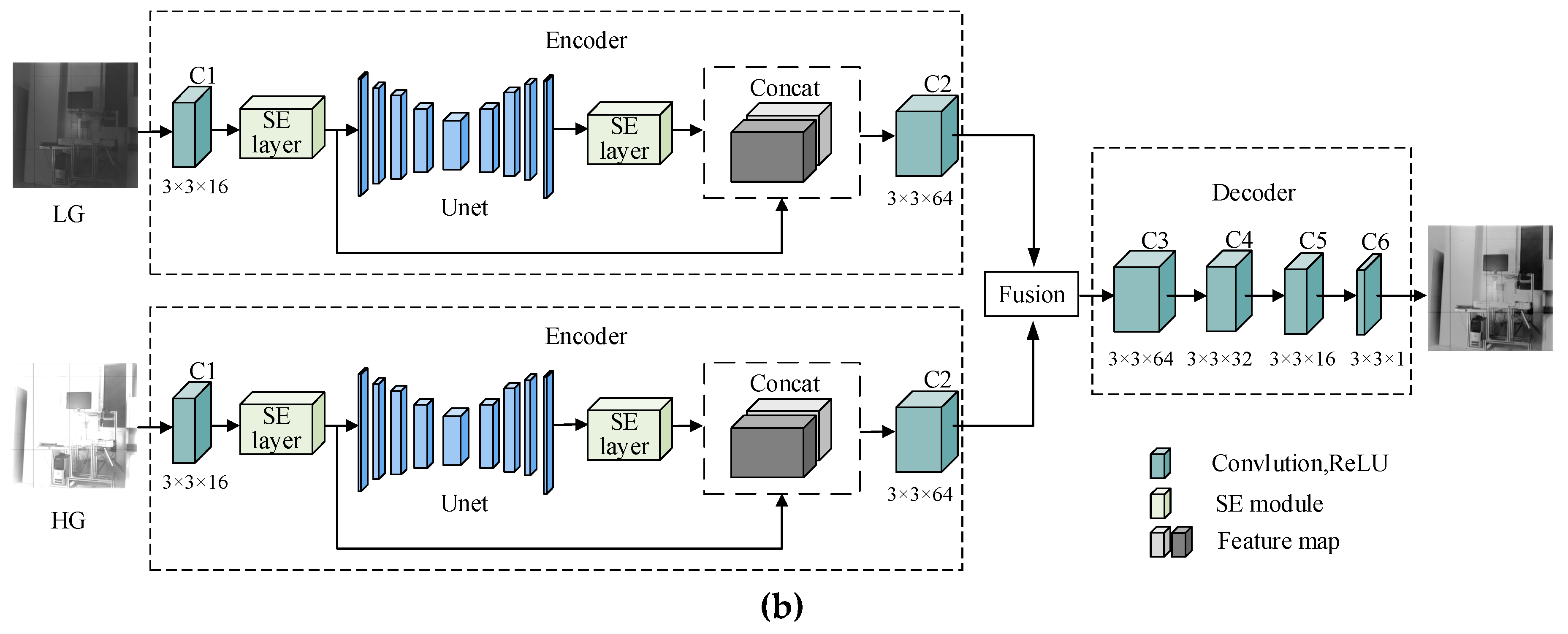
The framework of the proposed algorithm is shown in Figure 1. The network model primarily includes three types of functional units, namely the encoding, fusion, and decoding modules. The training network includes encoding and decoding modules for training feature extraction and reconstruction, respectively. The attention mechanism in the encoding module is employed to further extract important features hidden in coarse multi-channel and detailed features. The training structure is shown in Figure 1a, and we train the network directly without a fusion module.
Figure 1b shows the testing component of the network. Here, the encoding and decoding network comprising the optimal weights obtained in the training network is used. The inputs to the network layer are multi-gain images (HG and LG images), and the output is a fused image. To extract a multi-scale feature from the image, a convolution layer C1 is added before U-Net to extract coarse features, e.g. edges in the image. The feature map output by U-Net is concatenated with the output from C1 and then fused by C2, which helps retain the context and semantic information of the image. The feature map output by the convolution through a lightweight network SENet, which assigns different weights to different channels to extract image detail information. For simplicity, we refer to this network as (U-Net + SENet, U-SENet).
Through the above operations, the low-level and high-level information of the image are exploited to generate two-branch feature maps, which are then fused using an appropriate fusion strategy. Therefore, the fused feature map contains information on all scales of HG and LG images. Finally, the fused feature map is sent to the decoding network for reconstruction to obtain a high-dynamic range image. The specific parameters of U-SENet’s network structure are given in Table 1.
To extract the detailed information of each scale of the image, the training and testing modules include the U-Net network, which is a multi-scale, symmetrical and fully convolutional neural network and it contains two parts, that is, contraction and expanding paths. The contraction path, which is used for image feature extraction, primarily comprises convolution and pooling layers, and the expansion path, which is used to reduce the number of feature map channel, primarily comprises convolution and deconvolution layers. When processing up-sampling in the expansion path, feature maps with the same dimensional size of the feature extraction component and up-sampling component are concatenated using an operation to fuse the multi-scale information.
The encoding structure, fusion structure, decoding structure and loss function are described in the following.

3. U-SENet Network Structure

3.1. Encoding Structure

The proposed U-SENet feature extraction network structure primarily comprises two parts, the U-Net and SE layer. First, multi-gain images are input to C1 with a filter kernel size of 3 × 3 for course feature extraction to obtain a 16-channel feature map that contains the edge information of the original image. The feature map output from C1 is input into U-Net to extract deep features of the feature map, and output the feature map whose number of channels are still 16, the U-Net structure diagram is shown in Figure 2a. Connect the SE layer after C1 and U-Net respectively to maintain important information, for example as edges and suppress unnecessary information, such as noise. The structure of the SE layer is shown in Figure 2b. The skip connection operation facilitates gradient propagation and speeds up model convergence [20]; thus, we implement this operation in the encoding network to prevent gradient information from being lost during the convolution process. Similarly, the skip connection is performed between the output of the latter SE module and that of the previous SE module. Note that the two SE modules in the network are the same size. The encoding network has the following obvious advantages. First, the network structure of each branch learns the same features from the input image; thus, the types of feature maps output by convolution layers C1 and C2 are the same. Second, the ability to adaptively assign different weights to the channels is conducive to strengthening useful features. Third, shallow information is retained through the skip connection operations; thus, all significant features that eventually enter the fusion layer can be fully utilized.

3.2. Fusion Module

As shown in Figure 1, in the fusion module, the output feature maps of the two encoding branches (LG and HG) are of the same type and same number; thus, we use the addition method to fuse the corresponding feature map. The advantage of this fusion method is that the same types of features are added together by adding the pixel values at the same position in the same feature map. This method can effectively utilize the gradient information in the feature map, such that the fused feature map contains both the details of bright areas in the LG image and details of dark areas in the HG image, which helps retain significant information in the feature map. The calculation process is given in Equation (1).
f m ( i , j ) = k = 1 2 ϕ k m ( i , j )
where, m { 1 , 2 , , M } , M = 64 is the number of feature maps, i , j represents the pixel position in the feature map, k refers to the feature map index obtained from the input image, ϕ m represents the m -th feature map and f m is the m -th fusion feature map.

3.3. Decoding Module

As shown in Figure 1, the decoding module comprises convolutional layers C3, C4, C5 and C6. Here, the filter kernel size of each convolutional layer is 3 × 3 , the step size is 1 and the output of each layer is used as the input to the subsequent layer. Each time the feature map passes through a convolutional layer, the number of channels is halved, and the number of channels of the final convolutional layer output is 1, which helps reduce the number of the network model parameters. The fused feature map is input to the decoding module, and, by performing the convolution operation on the fused feature map and summing the convoluted feature maps, a reconstructed output image is obtained, as shown in Equation (2).
x j l = f ( i M j x i l 1 W l + b j ) .
W i = W i η E w i .
b i = b i η E b i .
In Equation (2), M j is the input map sequence, W is the transpose of the convolution kernel, b is the bias, represents the convolution operation, f is the activation function and x j is the output feature map after convolution, l represents the l -th convolutional layer. In Equations (3) and (4), E is the error cost function and η is the learning rate for gradient descent.

3.4. Loss Function

The network loss function [23] is given in Equation (5).
L = λ L s s i m + L p .
Here, L p represents the pixel loss of an image. The calculation formula is given as follows.
L p = O I 2 .
Here, I , O represent the input and output images, respectively.
Here, L s s i m , which represents the loss of structural similarity, is expressed as follows.
L s s i m = 1 S S I M ( O , I ) .
Here, S S I M is a type of measurement index representing the similarity between two images [19].
Note that the value range of L s s i m is in the range [ 0 , 1 ] and there is a difference with the value L p ; thus, we use λ to balance the two losses. We set λ = 1000.

4. Experiment Results

4.1. Hardware Platform

Figure 3 shows a dual-channel multi-gain camera and its imaging effect designed by our research team. The camera is designed based on the CMOS sensor GSENSE400BIS, and its main parameters are shown in Table 2. The image’s resolution that the camera output is 4096 (H) × 2048 (V), including two single-channel grayscale images arranged left and right (left: HG; right: LG; size: 2048 × 2048). To capture the details of bright and dark areas in the scene simultaneously, each pixel in the scene captured by the camera is simultaneously sampled once by the imaging unit with different gains to obtain two images of the same target scene with different gain values. Note that the grid lines in the image are auxiliary reference lines set because camera is in a debugging process. The computer parameters include are as follows: Intel (R) Xeon (R) Silver4110 [email protected] GHz, 32 GB memory, NVIDIA GeForce RTX2080 Ti, Windows 10, 64-bit operating system, Python 3.6.

4.2. Dasetset and Training Strategy

To train the encoding and decoding structures with superior performance and better feature extraction and reconstruction capabilities, we used grey image to train the weights of the network during training. Note that multi-gain images have no ground truth image; therefore, we use the public MS-COCO dataset [24] to train the network. The training set include 15,073 images, and the validation set include 10316 images, which is used to verify the network reconstruction capability after each iteration. All images are cropped from the middle to 256 × 256 and converted to grayscale images. The learning rate is 1 × 10 4 , and the batch size is 12.
The advantage of the training mode is that the testing stage can select a suitable fusion strategy adaptively to fuse feature maps when fixing network weights.

4.3. Validation

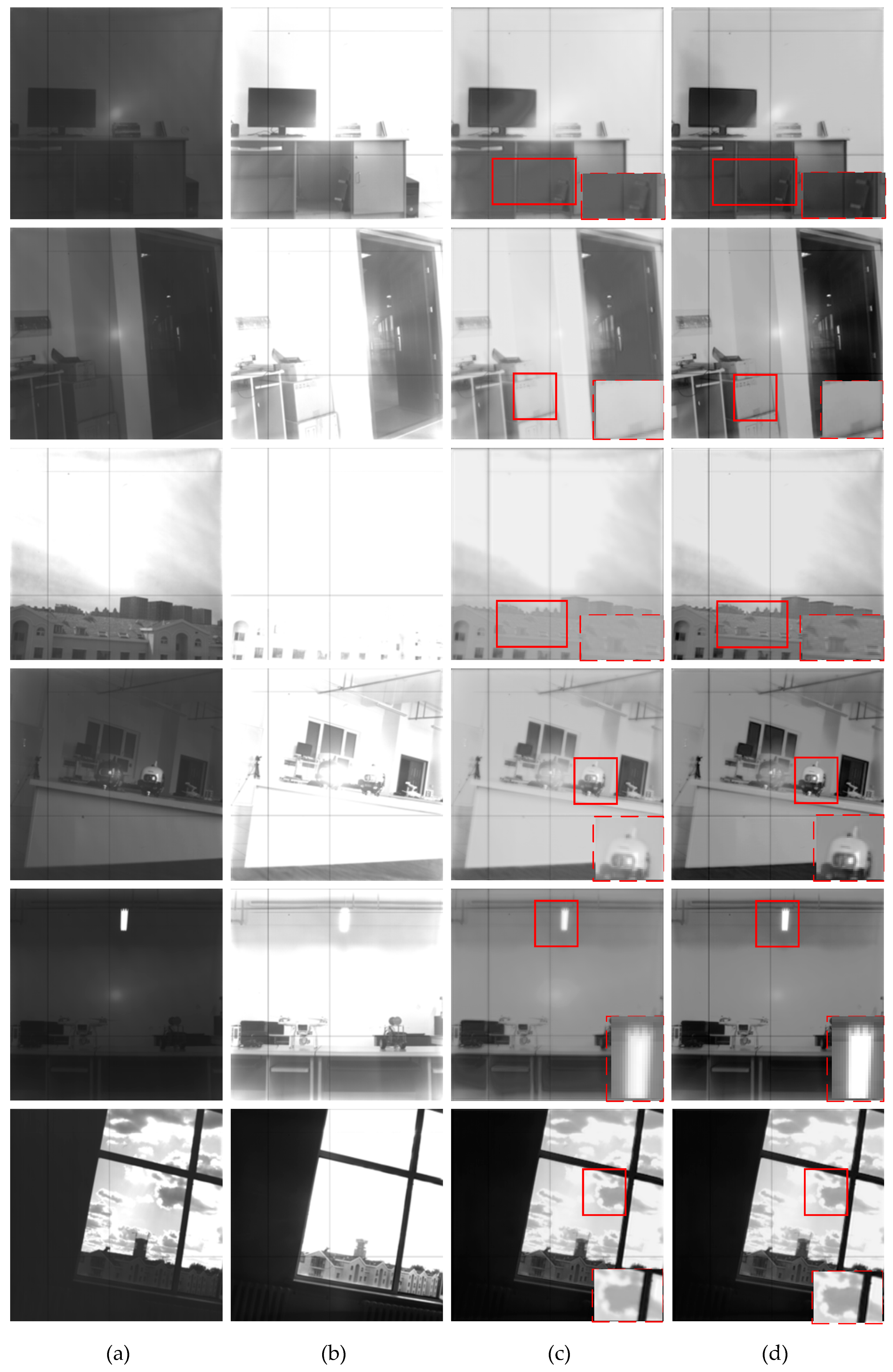
The first two rows in Figure 4 are the original experimental images, and the fourth row shows the experimental results obtained by the proposed algorithm. To verify the effectiveness of the proposed algorithm, four types of scenes were captured by the self-developed camera: insufficient lighting in the laboratory (scenes #1 and #2), normal indoor scenes (scene #4), outdoor scenes with strong light (scenes #3 and #6) and scenes with excessive indoor partial light (scene #5). These scenes were used to verify the algorithm’s effectiveness in normal scenes, its ability to retain scene details under strong and weak light conditions and its ability to suppress halo effects in images when the local area is too bright.
In this experiment, we set the number of epochs to 20, 30 and 40 to train the network. The corresponding loss curve is presented in Figure 5, which shows that both validation and test loss decreased relatively quickly during the initial training period. As the number of iterations increased, the loss decreased increasingly slowly. With 20 epochs, the network did not converge completely. For 30 and 40 epochs, training loss tended to be stable, validation loss fluctuated within a lower range and the network converged. Therefore, we select 30 epochs in this study.
In scenes #1 and #2, the textures in the HG and LG images are preserved, and the detailed texture part in the red rectangular area in the image is more natural. In scenes #3 and #6, the edges and textures of the clouds under strong light are clearer. In addition, the halo effect at the light source in scene #5 is suppressed effectively, and, scene #4 shows that the proposed algorithm is equally effective for normal conditions. To verify the effectiveness of the attention mechanism for the network, we removed the SE layer from the network proposed and performed network training and testing. The third row in Figure 4 shows the experimental results obtained without the SE layer. As can be seen, compared to the fusion result of the proposed algorithm, the quality of the image fusion result is low with no SE layer, and the overexposed image details and textures could not be recovered effectively. For example, in the roof area in scene #3, it is difficult to retain the details of insufficiently illuminated areas. The visual effect is poor, which demonstrates that SE layer effectively retains important details in the source image and improves the quality of the fused image.

4.4. Experimental Result and Analysis

Generally, the evaluation of image fusion algorithms is divided into subjective and objective evaluations [25]. A subjective evaluation is a qualitative evaluation of the visual effect after fusion, and an objective evaluation is a quantitative evaluation of various indicators of the fused image. Here we evaluate the performance of the proposed algorithm from these two perspectives.
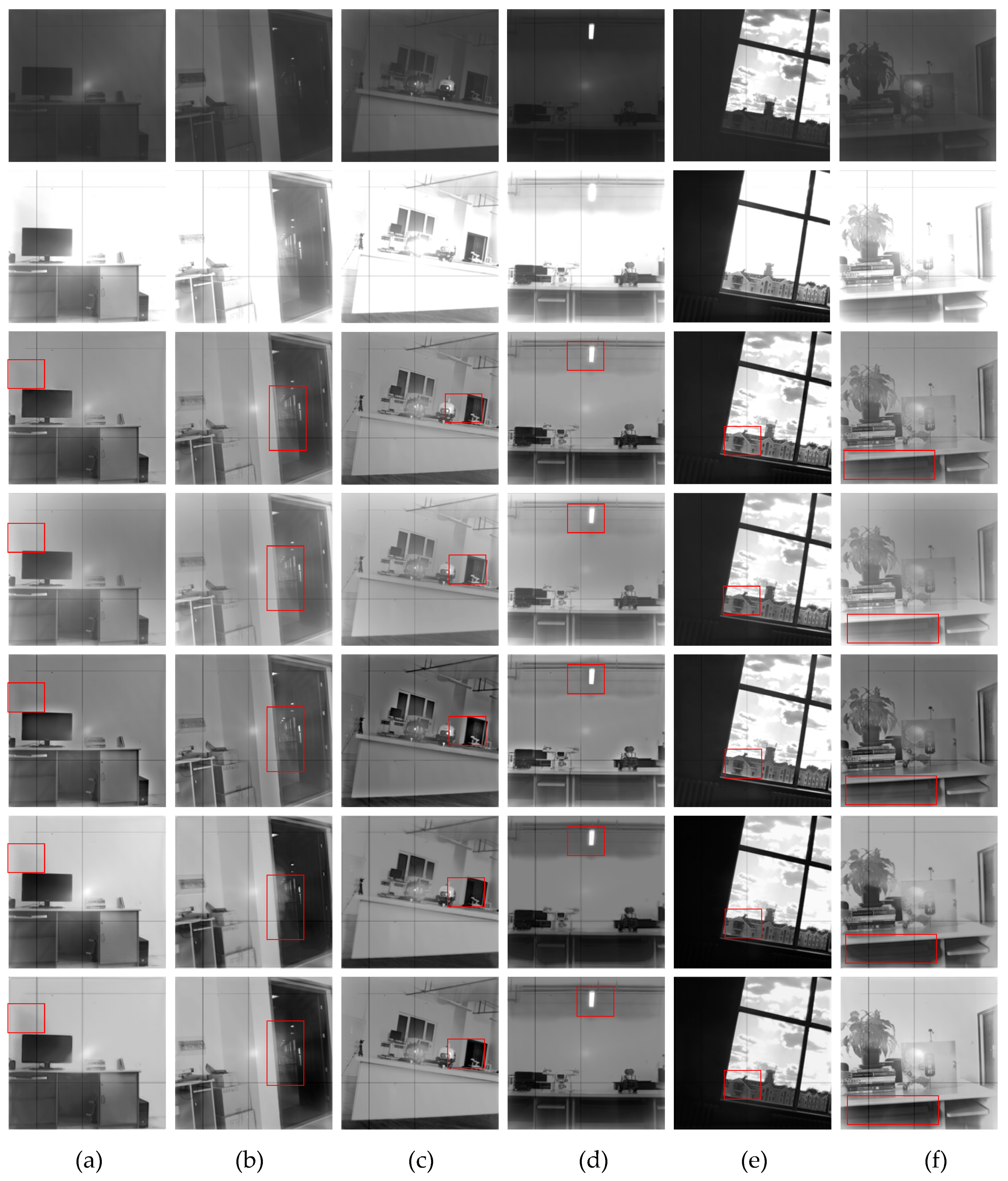
We randomly selected 12 sets of images from the captured dataset [26] to compare the performance of the proposed algorithm to similar algorithms. The compared algorithms include the DSIFT [11] algorithm, the multi-exposure image fusion algorithm proposed by Mertens [3], and a multi-exposure image fusion algorithm based on structural patch decomposition (SPD-MEF) [12] and the Deepfuse fusion method proposed by Prabhakar et al. [18].
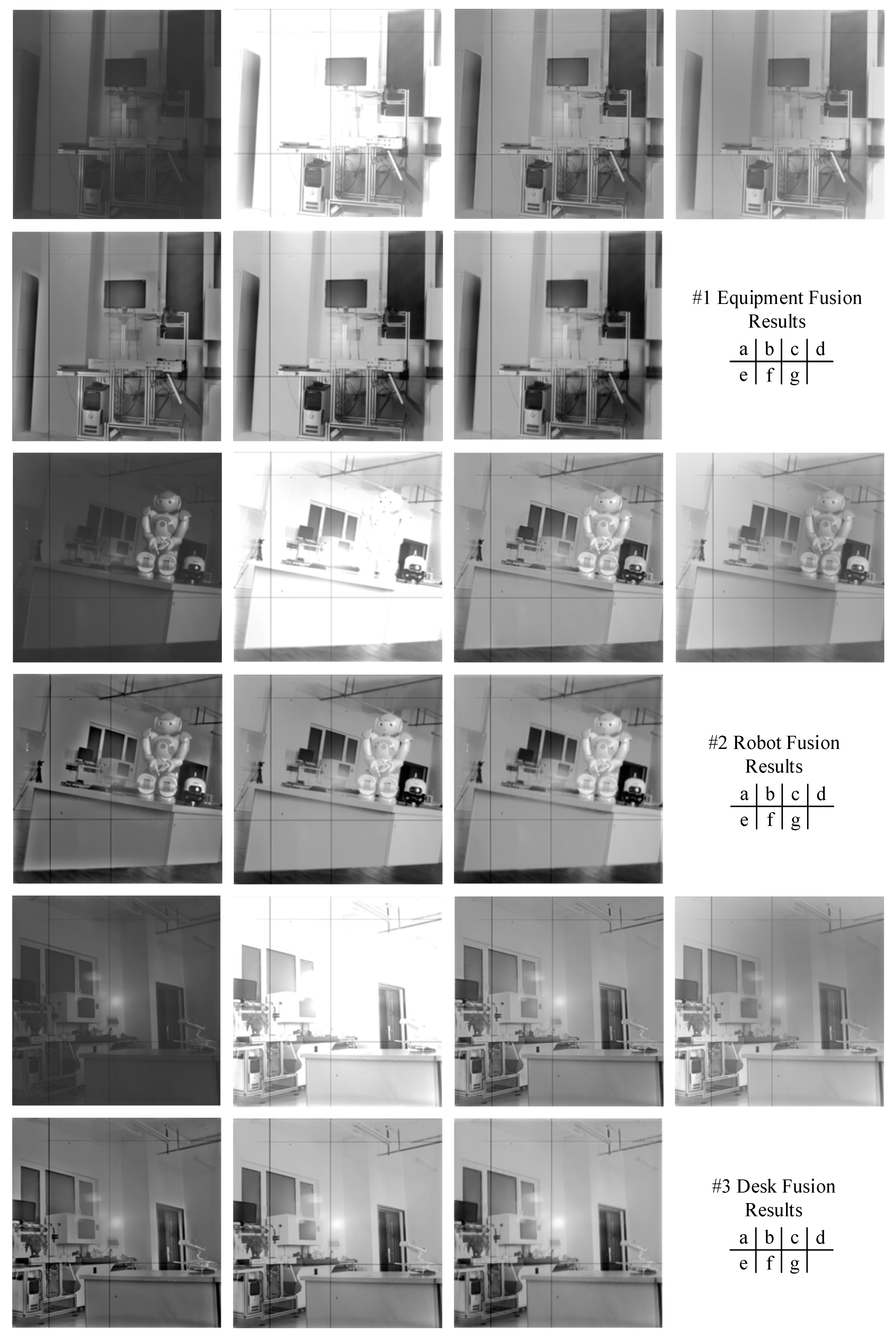
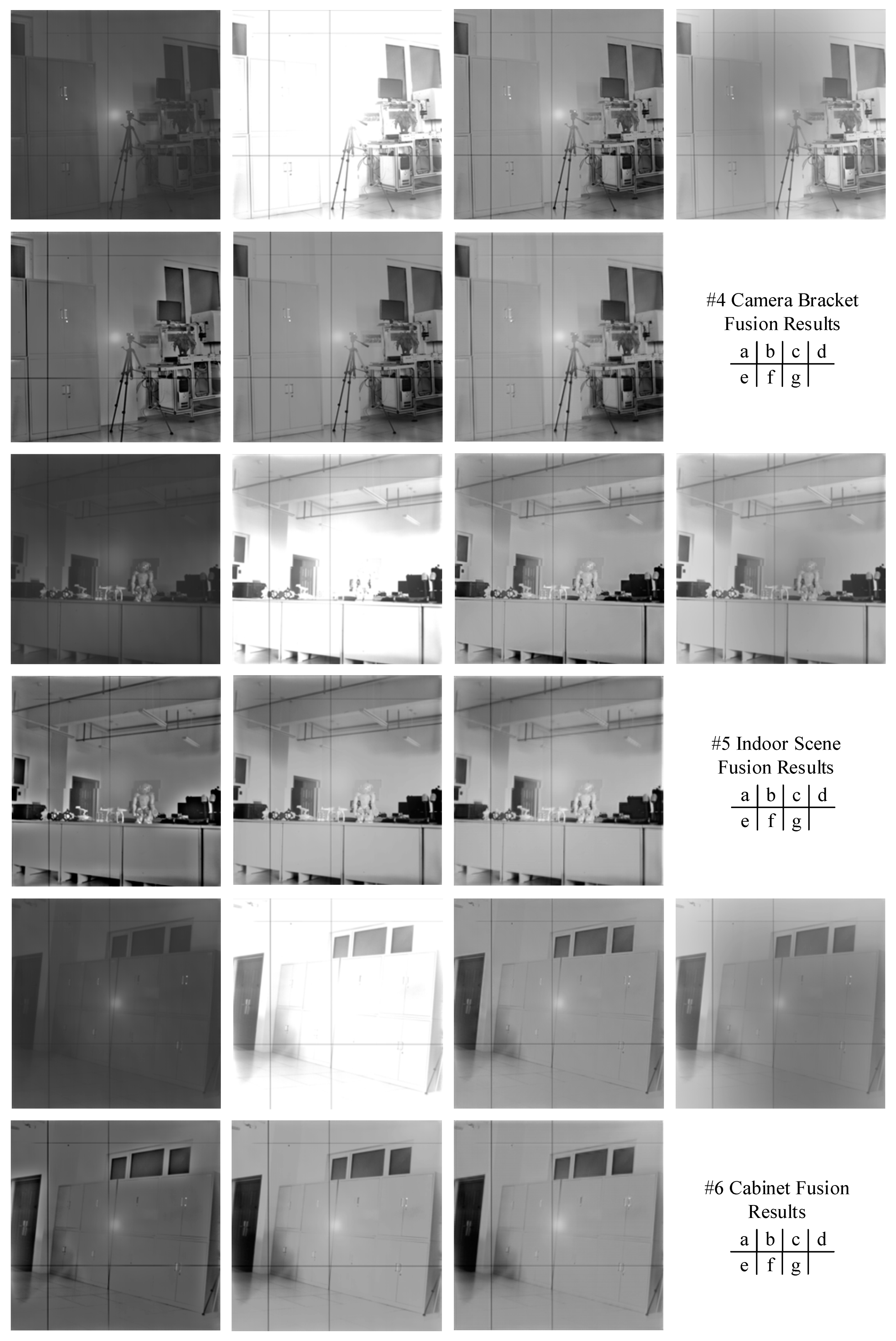
Figure 6 shows the fusion results of six different image pairs which are randomly selected from the 12 groups obtained by different algorithms, DSIFT, SPD-MEF and Deepfuse, respectively, and the seventh row shows the fusion result of the propose. The first two rows show the original multi-gain images, the third to sixth rows show the fusion results of Mertens algorithm. As can be seen, the fusion images obtained by the conventional Mertens, DSIFT and SPD-MEF methods are prone to local blur, low contrast and sufficient local details. Deepfuse cannot extract deep scale details of the image, because the feature extraction module is relatively simple, it only uses two convolutional layers.
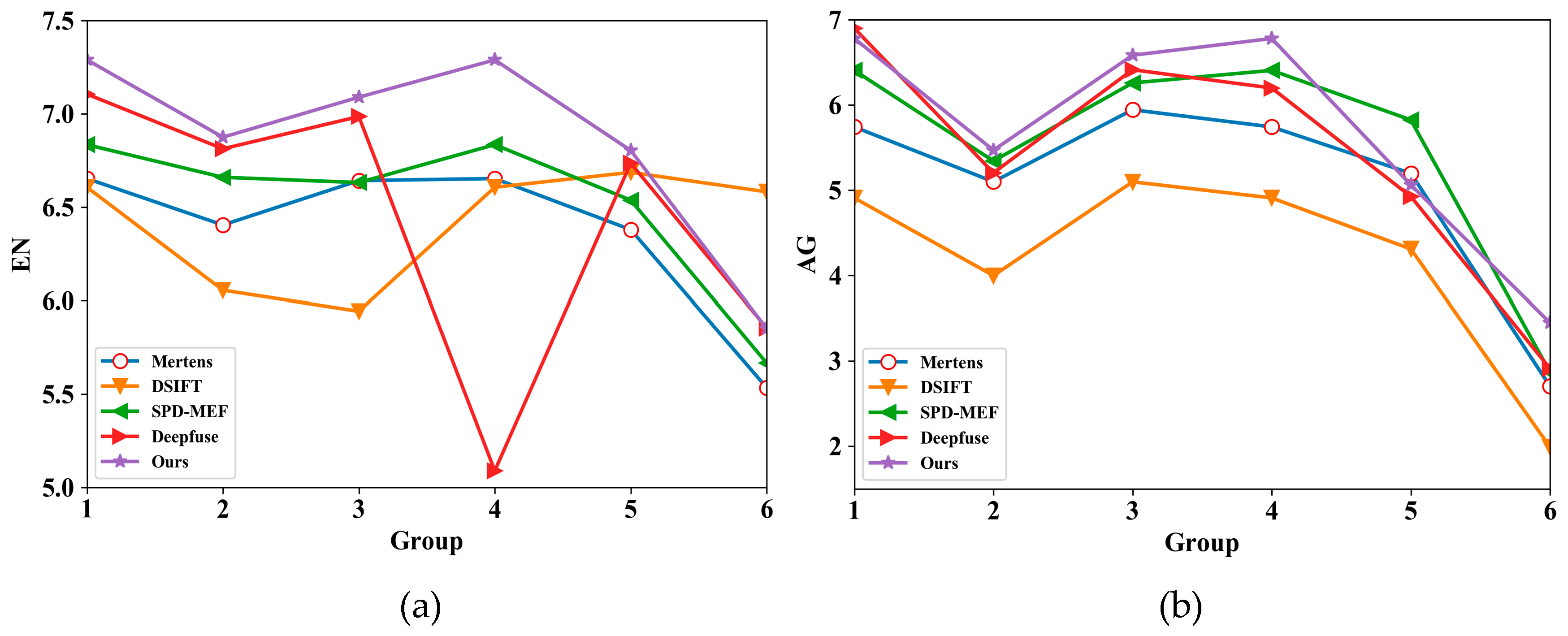
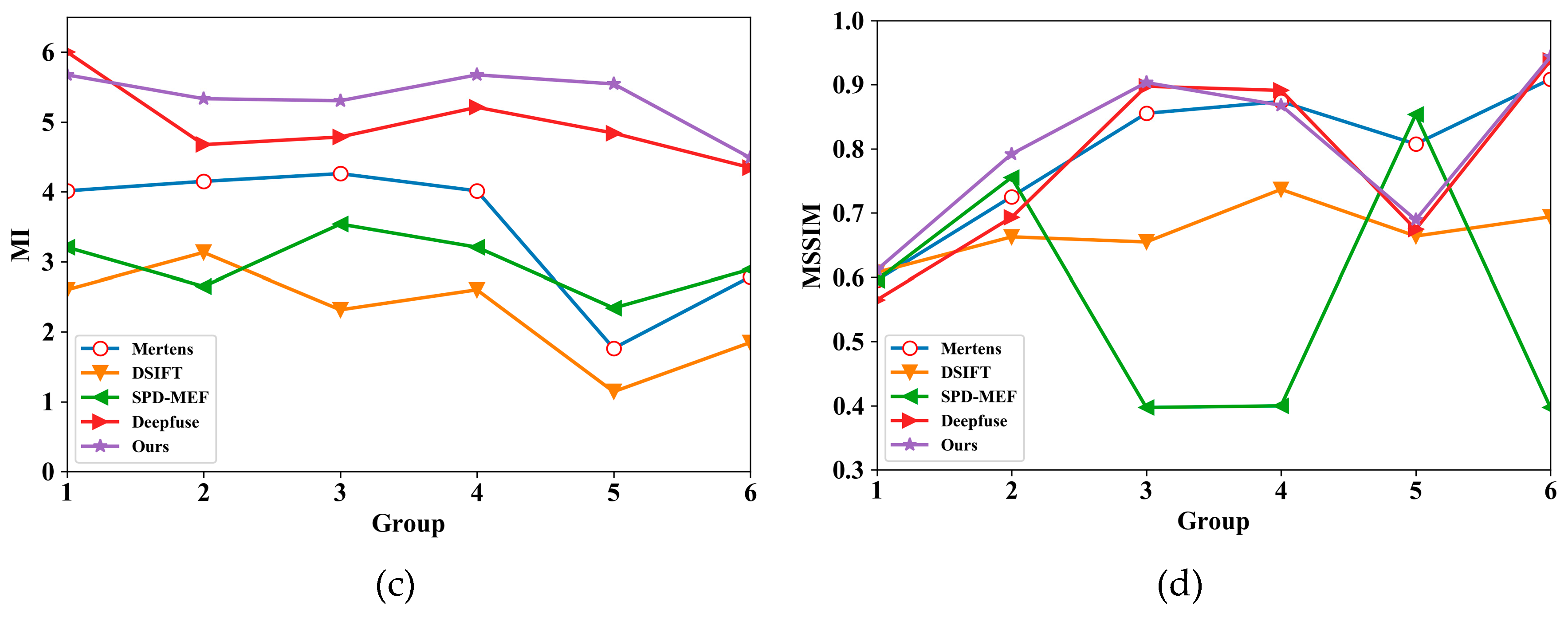
Table 3 indicates each fusion method’s performance for images in Figure 6 relative to index entropy (EN) [27], average gradient (AG) [28], mutual information (MI) [28] and multi-level structural similarity (MSSIM) [29], which totally include 30 fused images. Note that greater index values indicate better image fusion performance (numbers in bold indicate optimal values).
Figure 7 shows the trend curve corresponding to the data given in Table 3. Here, the X-axis represents each corresponding group of images and the Y-axis represents the index value.
As shown, compared to the compared methods, the proposed method demonstrates improvement in various indicators. EN is improved by 5.19%–7.66%, AG is improved by 4.8%–35.34%, MI is improved by 7.24%–79.54% and MSSIM is improved by 2.5%–43.11%. Obviously, the proposed method shows a great advantage relative to improving image quality.
Obviously, time complexity is important for HDR imaging. We mainly compare with Deepfuse in terms of the time complexity. The training parameters of Deepfuse and the proposed method are shown in Table 4. In the following experimental environment in Table 4, the training time of our method is about 15 h, Deepfuse can be saturated in about 10 min with fewer epochs, and the average time to fuse an image during testing in our method is 5.32s, while Deepfuse takes 0.58s. As shown, compared to Deepfuse, the proposed method does not occupy an advantage in time complexity. The main reason for this situation is that we use UNet as the feature extraction network, and adds the attention mechanism network SENet to the network. The entire network structure is deep, which leads to the higher time complexity.
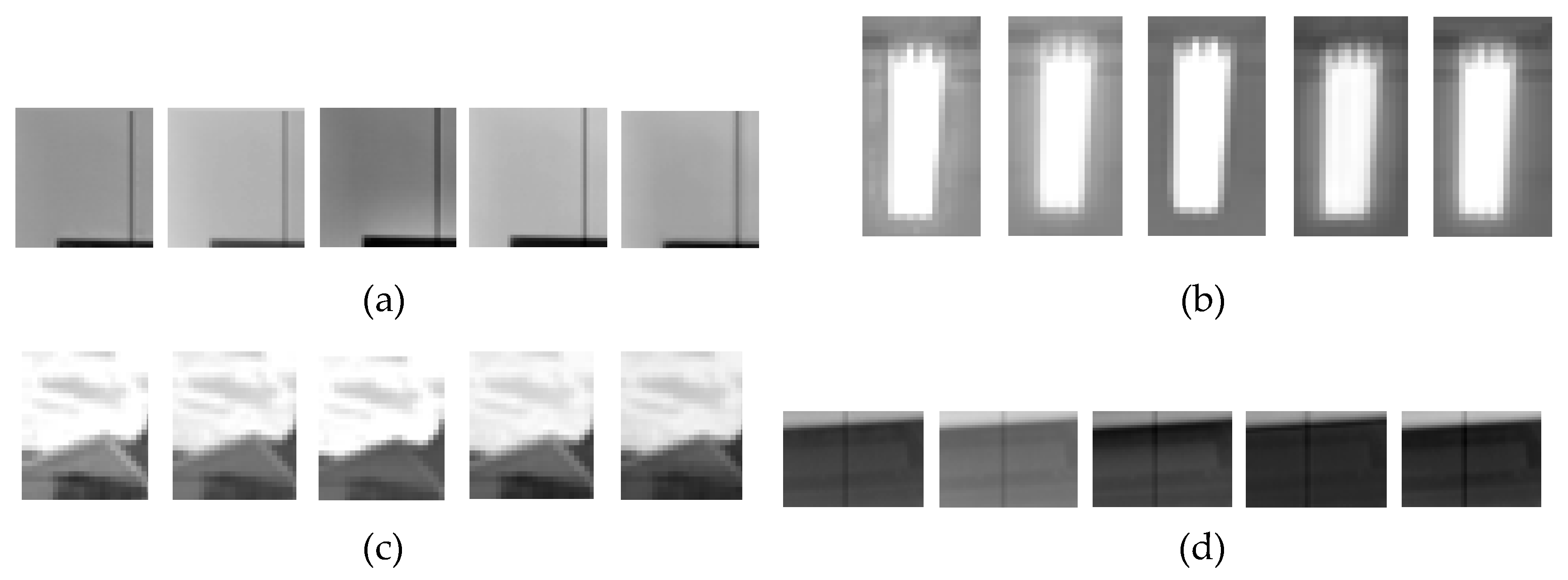
Figure 8 shows the fusion results of six other sets of images corresponding to different scenes. Here, for each scene, the proposed method obtained a better fusion effect. Figure 9 shows an enlarged comparison of various texture details. As can be seen, the Mertens and DSIFT algorithms are insufficient in extracting image details. The shaded area above the computer due to the reflection of the sunlight in Figure 9a and the clouds above the house in Figure 9c could not be recovered effectively. The SPD-MEF algorithm retains the details of the image; however, the fused image retains too much brightness information of the LG image, the overall image is darker and the image includes obvious halos, as shown in Figure 9a (above the computer area) and Figure 9b (the flashlight has an obvious halo effect). The fusion image obtained by Deepfuse demonstrates high contrast and uniform brightness distribution; however, there is room to improve the extraction of image details. The shadow areas above the computer in Figure 9a and the details of the keyboard table in Figure 9d were not extracted completely. The fusion results obtained by the proposed method demonstrate higher contrast, more uniform brightness distribution and better detail restoration. In addition, the proposed method and can effectively avoid halo effects, which provide a good visual effect.

5. Conclusions

In this paper, we have proposed a semi-supervised network to fuse multi-gain images captured by a dual-channel camera. Two multi-gain images are generated by the camera hardware simultaneously; thus, they are naturally immune to motion artifacts that tend to occur in traditional multi-exposure image fusion methods. The proposed method extracts texture details of multi-gain images through U-Net, emphasizes more valuable information using an attention mechanism SE layer and implements a skip connection mechanism to achieve effective extraction of the deep image features. Comparative experimental results demonstrate that the quality of the fused image obtained by the proposed method is higher, which effectively expands the dynamic range of the image. In addition, the proposed method achieves good results relative to various indexes, such as EN, AG, MI and MSSIM. Despite the above successes, it also exposed disadvantages in the experiment, which is high time complexity. Therefore, we will solve this problem to further improve the method performance in the future.

Author Contributions

M.F.: Conceptualization, Methodology, Formal analysis, Supervision. X.L.: Writing-original draft, Conceptualization, Methodology, Investigation. F.F.: Visualization, Methodology, Data curation. Y.S.: Visualization. Z.S.: Data curation, Software, Validation, Supervision. All authors have read and agreed to the published version of the manuscript.

Funding

This work was supported in part by Key Scientific and Technological Achievements Transformation Project of Jilin Province (No. 20170307002GX), Consulting research project of Chinese Academy of Engineering (2019-JL-4-2), Financially supported by the Marine S&T Fund of Shandong Province for Pilot National Laboratory for Marine Science and Technology (Qingdao) (No.2018SDKJ0102-6).

Conflicts of Interest

The author declares no conflict of interest.

References

  1. Kou, F.; Li, Z.; Wen, C.; Chen, W. Edge-preserving smoothing pyramid based multi-scale exposure fusion. J. Vis. Commun. Image Represent. 2018, 53, 235–244. [Google Scholar] [CrossRef]
  2. Guo, X.; Li, Y.; Ling, H. LIME: Low-light image enhancement via illumination map estimation. IEEE Trans. Image Process. 2016, 26, 982–993. [Google Scholar] [CrossRef] [PubMed]
  3. Mertens, T.; Kautz, J.; Van Reeth, F. Exposure fusion: A simple and practical alternative to high dynamic range photography. Comput. Graph. Forum 2009, 28, 161–171. [Google Scholar] [CrossRef]
  4. Zhao, C.; Guo, Y.; Wang, Y. A fast fusion scheme for infrared and visible light images in NSCT domain. Infrared Phys. Technol. 2015, 72, 266–275. [Google Scholar] [CrossRef]
  5. Que, Y.; Yang, Y.; Lee, H. Exposure Measurement and Fusion via Adaptive Multiscale Edge-Preserving Smoothing. IEEE Trans. Instrum. Meas. 2019. [Google Scholar] [CrossRef]
  6. Chen, C.; Li, Y.; Liu, W.; Huang, J. Image fusion with local spectral consistency and dynamic gradient sparsity. In Proceedings of the IEEE Conference on Computer Vision and Pattern Recognition, Columbus, OH, USA, 23–28 June 2014; pp. 2760–2765. [Google Scholar]
  7. Zhang, Q.; Liu, Y.; Blum, R.; Han, J.; Tao, D. Sparse representation based multi-sensor image fusion for multi-focus and multi-modality images: A review. Inf. Fusion 2018, 40, 57–75. [Google Scholar] [CrossRef]
  8. Chen, L.; Li, J.; Chen, C. Regional multifocus image fusion using sparse representation. Opt. Express 2013, 21, 5182–5197. [Google Scholar] [CrossRef] [PubMed]
  9. Burt, P.; Kolczynski, R. Enhanced image capture through fusion. In Proceedings of the 1993 (4th) International Conference on Computer Vision, Berlin, Germany, 11–14 May 1993; pp. 173–182. [Google Scholar]
  10. Li, S.; Kang, X.; Hu, J. Image fusion with guided filtering. IEEE Trans. Image Process. 2013, 22, 2864–2875. [Google Scholar] [PubMed]
  11. Liu, Y.; Wang, Z. Dense SIFT for ghost-free multi-exposure fusion. J. Vis. Commun. Image Represent. 2015, 31, 208–224. [Google Scholar] [CrossRef]
  12. Ma, K.; Li, H.; Yong, H.; Wang, Z.; Meng, D.; Zhang, L. Robust multi-exposure image fusion: A structural patch decomposition approach. IEEE Trans. Image Process. 2017, 26, 2519–2532. [Google Scholar] [CrossRef] [PubMed]
  13. Ma, K.; Duanmu, Z.; Yeganeh, H.; Wang, Z. Multi-exposure image fusion by optimizing a structural similarity index. IEEE Trans. Comput. Imaging 2017, 4, 60–72. [Google Scholar] [CrossRef]
  14. Li, H.; Manjunath, B.; Mitra, S. Multi sensor image fusion using the wavelet transform. Graph. Models Image Process. 1995, 57, 235–245. [Google Scholar] [CrossRef]
  15. Borwonwatanadelok, P.; Rattanapitak, W.; Udomhunsakul, S. Multi-focus image fusion based on stationary wavelet transform and extended spatial frequency measurement. In Proceedings of the 2009 International Conference on Electronic Computer Technology, Macau, China, 20–22 February 2009; pp. 77–81. [Google Scholar]
  16. Hill, P.; Canagarajah, C.; Bull, D. Image Fusion Using Complex Wavelets. In Proceedings of the BMVC, Tvbingen, Germany, 22−24 November 2002; pp. 1–10. [Google Scholar]
  17. Ma, X.; Hu, S.; Liu, S.; Fang, J.; Xu, S. Multi-focus image fusion based on joint sparse representation and optimum theory. Signal Process. Image Commun. 2019. [Google Scholar] [CrossRef]
  18. Prabhakar, K.; Srikar, V.; Babu, R. DeepFuse: A Deep Unsupervised Approach for Exposure Fusion with Extreme Exposure Image Pairs. In Proceedings of the ICCV, Venice, Italy, 22–29 October 2017; pp. 4724–4732. [Google Scholar]
  19. Li, H.; Zhang, L. Multi-exposure fusion with CNN features. In Proceedings of the 2018 25th IEEE International Conference on Image Processing (ICIP), Athens, Greece, 7–10 October 2018; pp. 1723–1727. [Google Scholar]
  20. Yan, Q.; Gong, D.; Zhang, P.; Shi, Q.; Sun, J.; Reid, I.; Zhang, Y. Multi-Scale Dense Networks for Deep High Dynamic Range Imaging. In Proceedings of the 2019 IEEE Winter Conference on Applications of Computer Vision (WACV), Waikoloa Village, HI, USA, 7–11 January 2019; pp. 41–50. [Google Scholar]
  21. Ronneberger, O.; Fischer, P.; Brox, T. U-net: Convolutional networks for biomedical image segmentation. In Proceedings of the International Conference on Medical Image Computing and Computer-Assisted Intervention, Munich, Germany, 5–9 October 2015; pp. 234–241. [Google Scholar]
  22. Hu, J.; Shen, L.; Sun, G. Squeeze-and-excitation networks. In Proceedings of the IEEE Conference on Computer Vision and Pattern Recognition, Salt Lake City, UT, USA, 18–23 June 2018; pp. 7132–7141. [Google Scholar]
  23. Li, H.; Wu, X. Densefuse: A fusion approach to infrared and visible images. IEEE Trans. Image Process. 2018, 28, 2614–2623. [Google Scholar] [CrossRef] [PubMed] [Green Version]
  24. Lin, T.; Maire, M.; Belongie, S.; Hays, J.; Perona, P.; Ramanan, D.; Dollar, P.; Lawrence Zitnick, C. Microsoft coco: Common Objects in Context. In Proceedings of the European Conference on Computer Vision, Zurich, Switzerland, 6–12 September 2014; pp. 740–755. [Google Scholar]
  25. Chen, J.; Li, X.; Luo, L.; Mei, X.; Ma, J. Infrared and visible image fusion based on target-enhanced multiscale transform decomposition. Inf. Sci. 2020, 508, 64–78. [Google Scholar] [CrossRef]
  26. Xu, L. Multi-Gain Dataset [EB/OL]. Available online: https://pan.baidu.com/s/1ku7nAz0ZHxjyvNJ_z2IvfA (accessed on 1 September 2019).
  27. Bai, X.; Zhou, F.; Xue, B. Edge preserved image fusion based on multiscale toggle contrast operator. Image Vis. Comput. 2011, 29, 829–839. [Google Scholar] [CrossRef]
  28. Qu, G.; Zhang, D.; Yan, P. Information measure for performance of image fusion. Electron. Lett. 2002, 38, 313–315. [Google Scholar] [CrossRef] [Green Version]
  29. Wang, Z.; Bovik, A.C.; Sheikh, H.R. Image quality assessment: From error visibility to structural similarity. IEEE Trans. Image Process. 2004, 13, 600–612. [Google Scholar] [CrossRef] [PubMed] [Green Version]
Figure 1. U-SENet network structure. (a) Training network; (b) Testing network.
Symmetry 12 00451 g001aSymmetry 12 00451 g001b
Figure 2. U-SENet feature extraction detailed structure. (a) U-Net structure, (b) SE layer structure.
Symmetry 12 00451 g002
Figure 3. Schematic of dual-channel camera output image.
Symmetry 12 00451 g003
Figure 4. The comparison of fusion results with and without SENet. (top to bottom: (a) #1; (b) #2; (c) #3; (d) #4; (e) #5; (f) #6, left to right: LG images, HG images, fusion results without SE layer and proposed fusion results).
Symmetry 12 00451 g004
Figure 5. Loss curve. (a) Epoch = 20; (b) Epoch = 30; (c) Epoch = 40.
Symmetry 12 00451 g005
Figure 6. Fusion results of different methods. ((a) LG image, (b) HG image, (c) Mertens, (d) DSIFT, (e) SPD-MEF, (f) Deepfuse, (g) the proposed method).
Symmetry 12 00451 g006aSymmetry 12 00451 g006b
Figure 7. Contrast curve charts of five fusion methods. (a) EN; (b) AG; (c) MI; (d) MSSIM.
Symmetry 12 00451 g007aSymmetry 12 00451 g007b
Figure 8. Comparison of image fusion results. (a) #7 (b) #8; (c) #9; (d) #10; (e) #11; (f) #12. Top to bottom: LG, HG image and fusion results obtained by the Mertens, DSIFT, SPD-MEF, Deepfuse and proposed methods.
Symmetry 12 00451 g008
Figure 9. Partially enlarged details in Figure 8. (a) #7; (b) #10; (c) #11; (d) #12 (from left to right for each small image: Mertens, DSIFT, SPD-MEF, Deepfuse, ours).
Symmetry 12 00451 g009
Table 1. U-SENet network parameter.
LayerParameter
(Convolution Kernel, Step)
Numbers of Output ChannelsSize of the Output
Convolution1 3 × 3 , s = 1 16 256 × 256
SE layer 16 256 × 256
Convolution 3 × 3 , s = 1 1 256 × 256
Conv1 3 × 3 , s = 1 16 256 × 256
Pool1 2 × 2 , s = 2 16 128 × 128
Conv2 3 × 3 , s = 1 32 128 × 128
Pool2 2 × 2 , s = 2 32 64 × 64
Conv3 3 × 3 , s = 1 64 64 × 64
Pool3 2 × 2 , s = 2 64 32 × 32
Conv4 3 × 3 , s = 1 128 32 × 32
Pool4 2 × 2 , s = 2 128 16 × 16
Conv5 3 × 3 , s = 1 256 16 × 16
Up6 3 × 3 , s = 2 128 32 × 32
Conv6-1 3 × 3 , s = 1 128 32 × 32
Conv6 3 × 3 , s = 1 128 32 × 32
Up7 3 × 3 , s = 2 64 64 × 64
Conv7 3 × 3 , s = 1 64 64 × 64
Up8 3 × 3 , s = 2 32 128 × 128
Conv8 3 × 3 , s = 1 32 128 × 128
Up9 3 × 3 , s = 2 16 256 × 256
Conv9 3 × 3 , s = 1 16 256 × 256
SE layer 16 256 × 256
Convolution2 3 × 3 , s = 1 64 256 × 256
Convolution3 3 × 3 , s = 1 64 256 × 256
Convolution4 3 × 3 , s = 1 32 256 × 256
Convolution5 3 × 3 , s = 1 16 256 × 256
Convolution6 3 × 3 , s = 1 1 256 × 256
Table 2. Main parameter of GSENSE400BIS sensor.
Optical Format2.0 InchFull Well Capacity (FWC) 90   k e
Active image size22.528 mm × 22.528 mmTemporal dark noise1.6 e
Pixel size11 um × 11 umDynamic range>93 db(HDR model)
Number of active pixels2048(H) × 2048(V)Supply voltage3.3 V for analog
1.8 V for digital
Shutter typeElectronic rolling shutterOutput format8 pairs of LVDS drivers
Pixel clock rate25 MHzPower consumption<650 mW
Frame rate24 fpsChromaMono
Data rate2.4 Gbit/s at 25 MHz pixel clockPackage115 pins PGA
Table 3. Comparison of index values under different algorithms.
MertensDSIFTSPD-MEFDeepfuseOurs
Group #1EN6.65306.60656.83467.10577.2891
AG5.74244.90936.40596.90026.7798
MI 4.01312.60183.20646.00325.6738
MSSIM0.59550.60740.59550.56480.6112
Group #2EN6.40436.05536.65996.81256.8746
AG5.09933.99785.34265.20355.4691
MI 4.14933.13242.64894.67505.3325
MSSIM0.72540.66270.75540.69310.7919
Group #3EN6.64205.94346.63166.98557.0891
AG5.94345.09826.25836.41336.5834
MI 4.25992.31493.53734.78465.3038
MSSIM0.85540.65470.39720.89760.9034
Group #4EN6.65306.60656.83465.08947.2891
AG5.74244.90936.40596.19886.7798
MI 4.01312.60183.20645.20975.6738
MSSIM0.87380.73670.39970.89110.8679
Group #5EN6.37936.68636.53716.73556.8036
AG5.19794.31045.82424.92585.0622
MI 1.76411.14272.34024.83995.5443
MSSIM0.80750.66390.85340.67430.6892
Group #6EN5.53476.58205.66675.85395.8510
AG2.70431.99132.87112.91293.4494
MI 2.78631.84732.89054.34534.4864
MSSIM0.90870.69400.39720.93770.9435
Table 4. The comparison of network parameters of training between Deepfuse and the proposed algorithm.
ParameterDeepfuseOurs
Epoch430
Batch Size212
Learning Rate 1 × 10 4 1 × 10 4