Article

Dynamical Properties of Fractional-Order Memristor

1
College of Electrical and Electronic Engineering, Anhui Science and Technology University, Bengbu 233100, China
2
College of Electronic and information Engineering, NanJing University of Aeronautics and Astronautics, NanJing 211106, China
*
Author to whom correspondence should be addressed.
Symmetry 2020, 12(3), 437; https://doi.org/10.3390/sym12030437
Submission received: 12 January 2020 / Revised: 20 February 2020 / Accepted: 27 February 2020 / Published: 9 March 2020
(This article belongs to the Special Issue Bifurcation and Chaos in Fractional-Order Systems)

Abstract

:
The properties of a fractional-order memristor is studied, and the influences of parameters are analyzed and compared. The results reflect that the resistance value of a fractional-order memristor can be affected by fraction-order, frequency, the switch resistor ratio, average mobility and so on. In addition, the circuit of a fractional-order memristor that is serially connected and connected in parallel with inductance and capacitance are studied. Then, the current–voltage characteristics of a simple series one-port circuits that are composed of a fractional-order memristor and a capacitor, or composed of a fractional-order memristor and a inductor are studied separately. The results demonstrate that at the periodic excitation, the memristor in the series circuits will have capacitive properties or inductive properties as the fractional order changes, the dynamical properties can be used in a memristive circuit.

1. Introduction

Fractional calculus, an important branch of mathematics, was born in 1695 and appeared almost simultaneously to classic calculus. Fractional calculus, in a narrow sense, mainly includes fractional differentials and fractional integrals, and it broadly includes fractional differences and fractional sum quotients. Since the theory of fractional calculus has been successfully applied to various fields in recent years, people have gradually discovered that fractional calculus can describe some non-classical phenomena in the fields of natural science and engineering applications. The current popular areas of fractional calculus include fractional numerical algorithms and fractional synchronization.
The successful development of a memristor has provided a new avenue for electronic technology and information technology, and it is expected to realize new functions. Their non-volatility makes memristors play a key role in memory, neural networks, and pattern recognition. Chua firstly defined a memristor (MR) in 1971 [1], and HP Labs reported the successful fabrication of nanoscale memristive devices [2]. A memristor is the fourth two-terminal fundamental circuit element with information storage ability and, as such, has attracted immense worldwide interest from both industry and academia [3]. Applications of MRs are used in many fields such as filter design, programmable logic, biological systems, and neural systems such as neural synaptic weighting with a pulse-based memristor circuit [4], Boolean logic operations and computing circuits based on memristors [5], and the voltage–current relationship of active memristors and frequency [6]. A generalized boundary condition memristor model was proposed in [7]. Research on a coupling behavior-based series-parallel flux-controlled memristor has been also conducted [8,9,10]. Two types of nanoscale nonlinear memristor models and their series-parallel circuit have been investigated [11], as have the characteristics of a memristor and its application in the circuit design [12,13,14,15,16,17]. First order mem-circuits have been studied [18]. Research on the equivalent analysis circuit of a memristors network [19], memristor-based adaptive coupling for consensus and synchronization [20,21,22], and coupling as a third relation in memristive systems have been proposed [23,24,25,26,27,28,29,30]. However, there is less research on fractional-order memristor, and there has been no literature physical background. In this paper, the analytical solution of parameter expression is derived by using a fractional-order memristor model in Section 2. The properties of fractional-order memristor is studied in Section 3, The results reflect that the resistance value of a fractional-order memristor can be affected by fraction-order, frequency, the switch resistor ratio, average mobility, and so on; additionally, the circuit of M α serially connected and connected in parallel with M α , L and C are also studied separately. Finally, the conclusion is presented in Section 4.

2. The Fractional Derivative

The α order Caputo derivative is defined as:
D t α x ( t ) = 1 Γ ( m a ) 0 t x ( m ) ( τ ) ( t τ ) 1 + α m d τ .
where m = [ α ] + 1 and Γ ( m ) is the Euler’s gamma function; when α ( 0 , 1 ) :
D t α e λ t = λ α e λ t .
Then, we obtain:
D t α e i ω t = ( i ω ) α e i ω t .
The real part and imaginary part of the sine and cosine functions can be obtained by separating Equation (3).
Some basic properties of Caputo fractional calculus are as follows.
(1)
D t α a [ u f ( t ) + v g ( t ) ] = u a D t α f ( t ) + v a D t α g ( t )
(2)
D t α a D t β a f ( t ) = D t β a D t α a f ( t ) = D t α + β a f ( t ) ,
(3)
D t α a L K = K t α Γ ( 1 α ) , α > 0
In which the constant K 0 , and the Caputo FD is D t α a C K = 0 , α > 0 .

3. The Model of Fractional-Order Memristor

The structure of an MR and its symbol are shown in Figure 1.
The mathematical model are defined as follows
v ( t ) = M α ( x ) i ( t ) .
M α ( x ) = R O N x + ( 1 x ) R O F F .
x ( t ) = k 0 D t α i ( t ) .
In which D t α is the α integral of x ( t ) , M α ( x ) is a fractional-order memristor when supposing the input current i ( t ) = I m sin ( ω t ) , switch resistor R O N = 100   Ω and R O F F = 10   k Ω , the current I m = 0.2   mA D = 10 nm, the average mobility u v = 10 14 m.s−1V−1, the length x 0 = 0.01, and the frequency ω = 5   rad / s . The transient current curve and the voltage curve of the memristor are shown in Figure 2a,b respectively.
The simulation result for when α has different values is shown in Figure 3a. It was found the an MR possesses memristive properties, with pinched hysteresis loops forming inclined “8”, and this property can be used to realize signal storage or computing. From Figure 3b, it can be seen that the smaller the value of fractional order, the greater the dynamic range amplitude of the resistance was.
The characteristic curves of a fractional-order memristor with different parameters are shown in Figure 4. From Figure 4a, it can be seen that the difference of resistance decreased as the frequency ω increased. From Figure 4b, it can be seen that the switch resistor increased and the curves of v i were inclined to right. From Figure 4c, it can be seen that the difference of resistance increased as the value of μ v increased.

4. The Properties of Fractional-Order Memristor

The fractional-order memristor in six cases of connection, serially and in parallel, are discussed in this section.

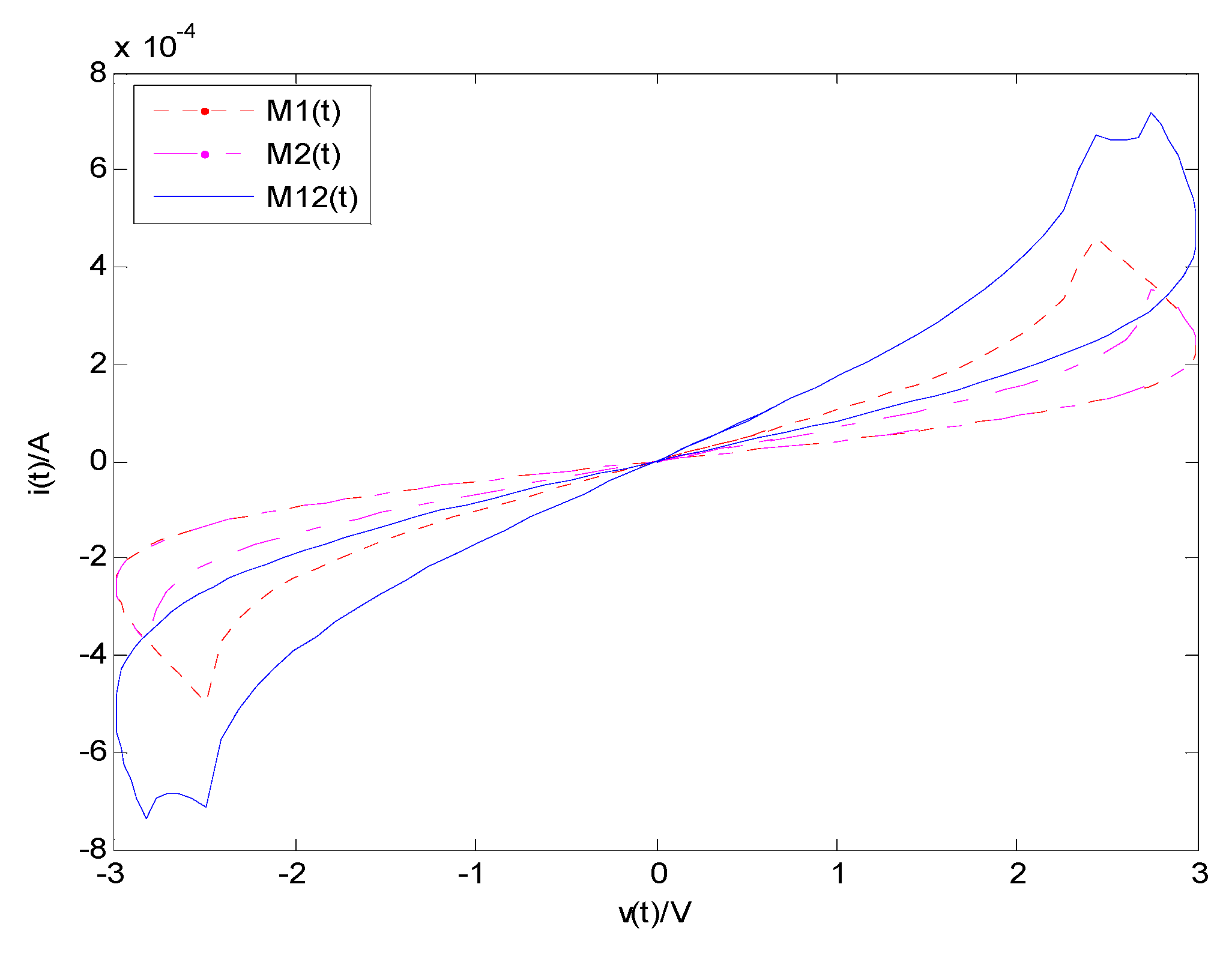
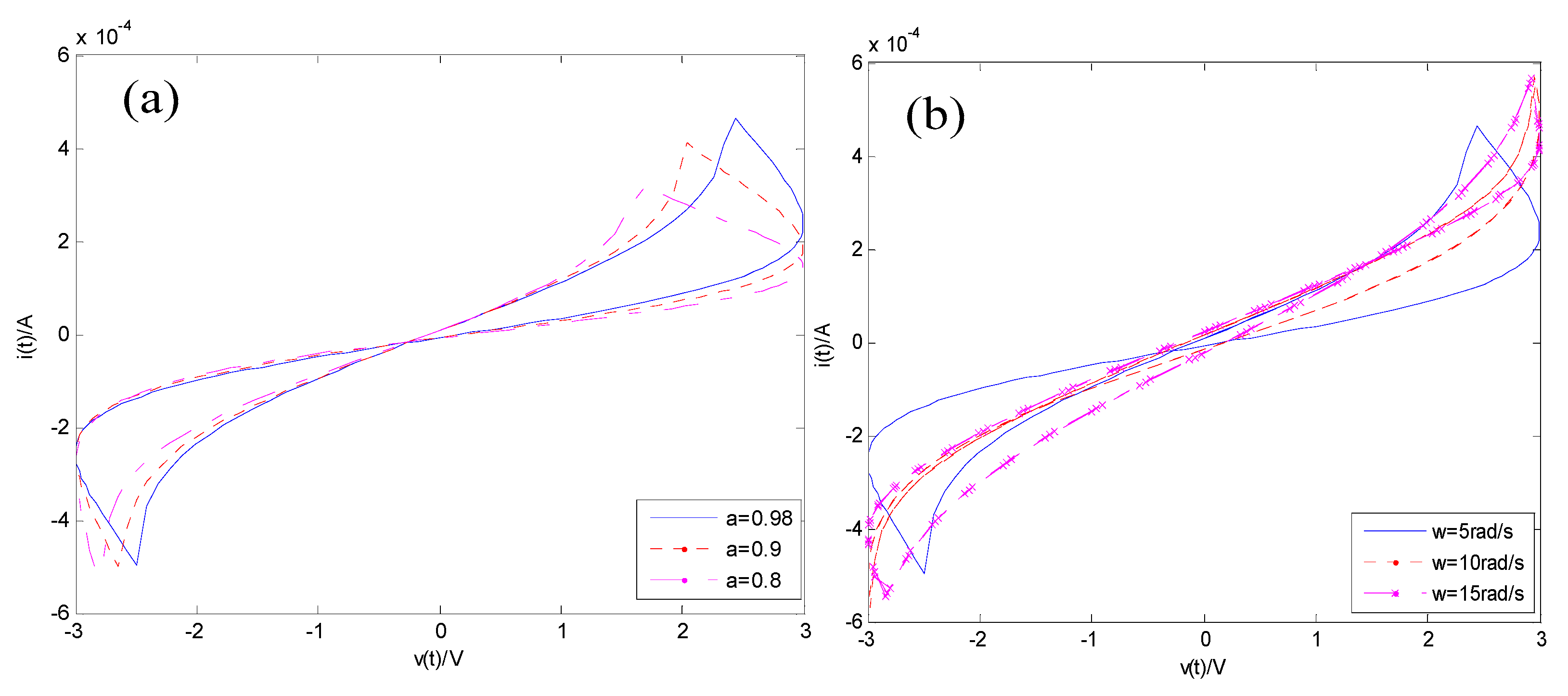
4.1. The Two Fractional-Order Memristors in Serial

The serial circuit of two fractional-order memristors is shown in Figure 5.
By choosing the current i ( t ) = I m sin ( ω t ) , based on the Caputo differential, Euler’s formulas, and the separating variables method, we obtain:
x ˙ ( t ) = k D t 1 α i ( t ) = k I [ D t 1 α sin ω t ] .
When t > > 1 , Equation (11) can be simplified as:
x ˙ ( t ) k I ω 1 α sin ( ω t + 1 α 2 π ) .
Then, the two sides of Equation (12) can be integrated to get:
x ( t ) x ( 0 ) + k I ω α [ cos ( 1 α 2 π ) cos ( ω t + 1 α 2 π ) ] .
By choosing the parameters M1( u v = 10 14 m.s−1V−1), M2( u v = 2 × 10 14 m.s−1V−1), and α = 0.98 , one can obtain the curves of v i that are are shown in Figure 6.
It was found the two serial MRs also possessed the memristive properties with pinched hysteresis loops behaving as inclined “8”, as shown in Figure 6. It can be seen that the values of M1, M2 and M12 are increased with the value of v(t), and the value of M12 is bigger than those of M1 and M2.

4.2. The Circuit of Fractional-Order MR in Parallel

The circuit of two fractional-order MRs in parallel is shown in Figure 7. According to Equations (4b) and (4c), it be written as:
M α ( x ) x ˙ ( t ) = k 0 D t α M α ( x ) i ( t ) .
M α ( x ) x ˙ ( t ) = k 0 D t α v ( t ) .
By choosing the voltage v ( t ) = V m sin ( ω t ) , one can obtain:
M α ( x ) x ˙ ( t ) = k 0 V m D t 1 α sin ( ω t ) x ˙ ( t ) = k D t 1 α i ( t ) = k I [ D t 1 α sin ω t ] .
When t > > 1 ,Equation (11) can be simplified as:
M α ( x ) x ˙ ( t ) k 0 V m ω 1 α sin ( ω t + 1 α 2 π ) .
and
[ R O N x + R O F F ( 1 x ) ] ( x x 0 ) k V m ω α [ cos ( 1 α 2 π ) cos ( ω t + 1 α 2 π ) ] .
( R O N R O F F ) x 2 + [ ( 1 + x 0 ) R O F F R O N x 0 ] x = k V m ω α [ cos ( 1 α 2 π ) cos ( ω t + 1 α 2 π ) ] + R O F F x 0 .
Then, one can set A = R O N R O F F ; B = ( 1 + x 0 ) R O F F R O N x 0 ; H = k V m ω α [ cos ( 1 α 2 π ) cos ( ω t + 1 α 2 π ) ] + R O F F x 0
and we can obtain:
A x 2 + B x + H = 0 .
x 1 = B + B 2 4 A H 2 A ; x 2 = B B 2 4 A H 2 A .
The value of M α ( x ) can be calculated.
To further study the dynamic behaviors of this MR circuit in parallel, the parameters were configured as the following: the input voltage v ( t ) = V m sin ω t , and the parameters R O N 1 = 100   Ω , R O F F 1 = 10   k Ω , V m = 3   V , D = 10 nm, u v = 10 14 m.s−1V−1, R O N 2 = 120   Ω , R O F F 2 = 18   k Ω , and ω = 5. The simulation result when using these parameters is shown in Figure 8.
It was found the two MRs that were connected in parallel also possessed the memristive properties with pinched hysteresis loops which are hown in Figure 8.

4.3. The Circuit of Fractal-Order Memristor and Capacitor That Are Serially Connected

The fractional-order memristor M α ( t ) and serially connected capacitor C are shown in Figure 9. By assume the current i ( t ) = I m sin ω t , M expresses the memristor, and C is the capacitor.
We can obtain:
v ( t ) = u C ( t ) + u M α ( t ) = u C ( t 0 ) + 1 C t 0 t i C ( t ) d t + i M α ( t ) M α ( t ) = u C ( t 0 ) + I cos ( ω t 0 ) C ω I cos ( ω t ) C ω B sin ( 1 α 2 π ) + A sin ( ω t ) + B sin ( 2 ω t + 1 α 2 π ) .
where
A = ( R O N R O F F ) [ x ( 0 ) + I k ω α ( cos 1 α 2 π ) ] I + R O F F I .
B = ( R O F F R O N ) k I 2 2 ω α .
The simulation result is shown in Figure 10. From Figure 10a, it can be seen as the parameter α decreased, the area of hysteresis loops increased and the difference of resistance increased with same current. From Figure 10b, it can be seen that if the parameters α and C were not varied, as ω increased, the area of hysteresis loops decreased. From Figure 10c, it can be seen that if the parameters α and ω were not varied, the area of hysteresis loops was not almost changed and the capacitor has little effect on the circuit.

4.4. The Circuit of Fractal-Order Memristor and Capacitor That Were Connected in Parallel

A memristor and a capacitor which were connected in parallel are shown in Figure 11, we can assume that v ( t ) = V m sin ( ω t ) , ω ( 0 ) = 0 , V m is the voltage magnitude.
By applying Kirchhoff’s current law (KCL), the current of circuit can be written as:
i ( t ) = v ( t ) M α ( t ) + C d v ( t ) d t = v ( t ) M α ( t ) + ω C V m cos ( ω t ) .
Additionally, when the parameters α and ω were chosen as different values, it can be seen the circuit of a memristor and a capacitor that were connected in parallel also possessed the memristive properties with pinched hysteresis loops which are shown in simulations in Figure 12a,b.

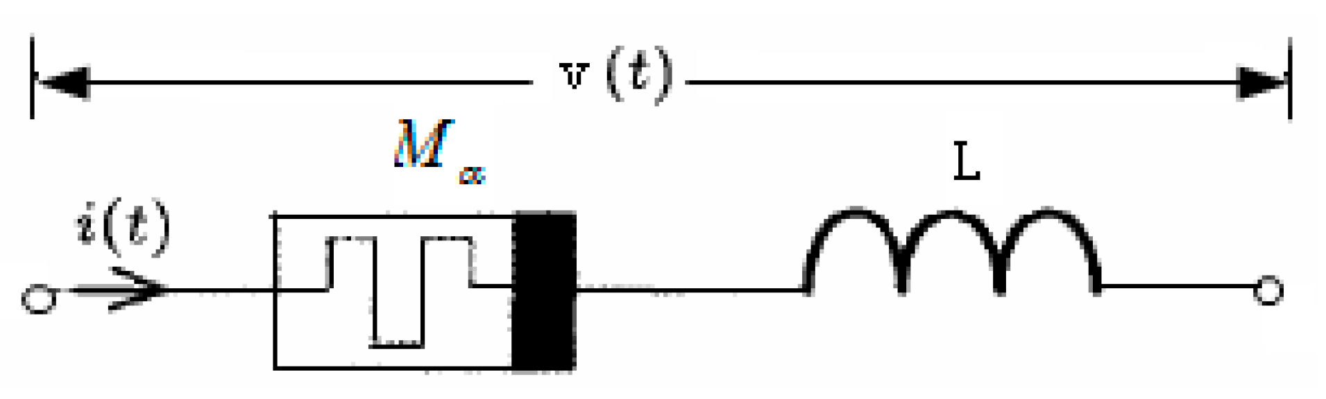
4.5. The Circuit of Fractal-Order Memristor and Inductor That Are Serially Connected

The circuit of the memristor and serially connected inductor are shown in Figure 13, where we assumed i ( t ) = I m sin ( ω t ) , ω ( 0 ) = 0 .
The voltage was:
v ( t ) = u L ( t ) + u M α ( t ) = L d i L ( t ) d t + i M α ( t ) M α ( t ) = I L ω cos ( ω t ) + A sin ( ω t ) + B [ sin ( 2 ω t + 1 α 2 π ) sin ( 1 α 2 π ) ] = u C ( t 0 ) + I cos ( ω t 0 ) C ω I cos ( ω t ) C ω B sin ( 1 α 2 π ) + A sin ( ω t ) + B sin ( 2 ω t + 1 α 2 π ) .
and
A = ( R O N R O F F ) [ x ( 0 ) + I k ω α ( cos 1 α 2 π ) ] I + R O F F I .
B = ( R O F F R O N ) k I 2 2 ω α .
The simulation result is shown in Figure 14. From Figure 14a, it can be seen that as the parameters ω and L were not varied, because as α decreased, the area of hysteresis loops increased and the difference of resistance increased with the same current. From Figure 14b, it can be seen that if the parameters α and L were not varied, as ω increased, the area of the hysteresis loops decreased. From Figure 14c, it can be seen that if the parameters α and ω were not varied, the area of the hysteresis loops was not almost changed, and it is shown that the inductor barely affected the circuit.

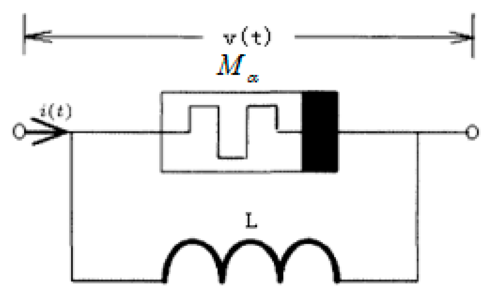
4.6. The Circuit of Fractal-Order Memristor and Inductor Connected in Parallel

A memristor and a capacitor that were connected in parallel are shown in Figure 15. By assuming the voltage v ( t ) = V m sin ( ω t ) , ω ( 0 ) = 0 , V m can be found as the voltage amplitude. By applying Kirchhoff’s current law (KCL), the current of circuit can be written as:
L d i L ( t ) d t = v ( t ) = V m sin ( ω t ) .
i L ( t ) = V m ω L [ 1 cos ( ω t ) ] .
i ( t ) = i M α ( t ) + i L ( t ) = v ( t ) M α ( t ) + V m ω L [ 1 cos ( ω t ) ] .
The simulation is shown in Figure 16a,b. It can be seen the circuit of the memristor and inductor that were connected in parallel also possessed memristive properties with pinched hysteresis loops. From Figure 16a, it can be seen the area of pinched hysteresis loops increased with α increased. From Figure 16b, it can be seen the area of the pinched hysteresis loops decreased with the ω increased.

5. Conclusions

In summary, this paper has presented a fractional-order memristor model and verifies the three essential characteristics of a fractional-order memristor. In addition, the properties of fractional-order memristor have been described. In a simple memristive series circuit, with a change of the fractional derivative order, the series circuit of a fractional-order memristor and a capacitor or inductor shows a conversion from a pure capacitor circuit to a memristive circuit. The series circuit shows conversions of purely inductive and memristive circuits. Here, analytical solutions were derived by a fractional-order memristor, the properties of fractional-order memristor model parameters were obtained, and simulation results were given. The results showed that material properties determine the order of the fractional derivative, so the best memory capacity of a physical memristor can be achieved by finding materials that are compatible with the excitation frequency.

Author Contributions

Conceptualization, S.F.W. and A.Y.; methodology, S.F.W; software, S.F.W.; validation, S.F.W. and A.Y.; formal analysis, S.F.W.; investigation, S.F.W.; resources, S.F.W.; data curation, S.F.W.; writing—original draft preparation, S.F.W.; writing—review and editing, S.F.W.; visualization, S.F.W.; supervision, S.F.W.; project administration, S.F.W.; funding acquisition, A.Y. All authors have read and agreed to the published version of the manuscript.

Funding

This work was supported by the Foundation of The University Synergy Innovation Program of Anhui Province under Grant GXXT-2019-019 and Key R&D Projects of Anhui Science and Technology Department under Grand 201904f06020022.

Conflicts of Interest

The authors declare that there is no conflict of interest regarding the publication of this paper.

References

  1. Chua, L.O. Memristor—The missing circuit element. IEEE Trans. Circuit Theory 1971, CT-18, 507–519. [Google Scholar] [CrossRef]
  2. Strukov, D.B.; Snider, G.S.; Stewart, D.R.; Williams, R.S. The missing memristor found. Nature 2008, 453, 80–83. [Google Scholar] [CrossRef] [PubMed]
  3. Yu, D.; Iu HH, C.; Liang, Y.; Fernando, T.; Chua, L.O. Dynamic Behavior of Coupled Memristor Circuits. IEEE Trans. Circuits Syst. I Regul. Pap. 2015, 62, 1607–1615. [Google Scholar] [CrossRef]
  4. Kim, H.; Sah, M.P.; Yang, C.; Roska, T.; Chua, L.O. Neural synaptic weighting with a pulse-based memristor circuit. IEEE Trans. Circuit Syst. I Reg. Pap. 2012, 59, 148–158. [Google Scholar] [CrossRef]
  5. Papandroulidakis, G.; Vourkas, I.; Vasileiadis, N.; Sirakoulis, G.C. Boolean logic operations and computing circuits based on memristors. IEEE Trans. Circuits Syst. II Exp. Briefs. 2014, 61, 972–976. [Google Scholar] [CrossRef]
  6. Bao, B.-C.; Zou, X. Voltage-Current Relationship of Active Memristor and Frequency Characteristic of Active Memristive Circuit. Acta Electron. Sin. 2013, 41, 593–596. [Google Scholar]
  7. Ascoli, A.; Corinto, F.; Tetzlaff, R. Generalized boundary condition memristor model. Int. J. Circuit Theor. Appl. 2015, 44, 60–84. [Google Scholar] [CrossRef]
  8. Wang, Y.; Yang, J. Research of coupling behavior based series-parallel flux-controlled memristor. Acta Phys. Sin. 2015, 64, 237303. [Google Scholar]
  9. Sozen, H. First-order memristor–capacitor filter circuits employing hp memristor. J. Circuits Syst. Comput. 2014, 23, 1450116. [Google Scholar] [CrossRef]
  10. Song, D.-H.; Lü, M.-F.; Ren, X.; Li, M.-M.; Zu, Y.-X. Basic properties and applications of the memristor circuit. Acta Phys. Sin. 2012, 61, 118101. [Google Scholar]
  11. Dong, Z.-K.; Duan, S.-K. Two types of nanoscale nonlinear memristor models and their series-parallel circuit. Acta Phys. Sin. 2014, 63, 128502. [Google Scholar]
  12. Wang, Q.-H.; Song, W.-P. Characteristics of memristor and it’s application in the circuit design. Electron. Compon. Mater. 2014, 33, 5–7. [Google Scholar]
  13. Frasca, M.; Gambuzza, L.V. Implementation of adaptive coupling through memristor. Phys. Status Solidi 2015, 12, 206–210. [Google Scholar] [CrossRef]
  14. Gambuzza, L.-V.; Buscarino, A. Memristor-Based Adaptive Coupling for Consensus and Synchronization. IEEE Trans. Circuits Syst. I Regul. Pap. 2015, 62, 1175–1184. [Google Scholar] [CrossRef]
  15. Wang, T.-S.; Zhang, R.-D. Properties of memristor in RLC circuit and diode circuit. Acta Phys. Sin. 2014, 63, 178101. [Google Scholar]
  16. Duan, S.-K.; Hu, X.-F. Memristor-based RRAM with applications. Sci. China 2012, 42, 754–768. [Google Scholar] [CrossRef]
  17. Yu, Y.J.; Wang, Z.H. A fractional-order memristor model and the fingerprint of the simple series circuits including a fractional-order memristor. Acta Phys. Sin. 2015, 64, 238401. [Google Scholar]
  18. Riaza, R. First Order Mem-Circuits: Modeling, Nonlinear Oscillations and Bifurcations. IEEE Trans. Circuits Syst. I Regul. Pap. 2013, 60, 1570–1582. [Google Scholar] [CrossRef] [Green Version]
  19. He, B.-X.; Bao, B.-C. Research on the Equivalent Analysis Circuit of Memristors Network and Its Characteristics. J. Electron. Inf. Technol. 2012, 34, 1252–1256. [Google Scholar]
  20. Yuan, F.; Wang, G.-Y. Study on dynamical characteristics of a meminductor model and its meminductor-based oscillator. Acta Phys. Sin. 2015, 64, 210504. [Google Scholar]
  21. Xu, H.; Tian, X.B. Influence of temperature change on conductive characteristics of titanium oxide memristor. Acta Phys. Sin. 2014, 63, 098402. [Google Scholar]
  22. Papoutsidkis, M.; Kalovrektis, K.; Drosos, C. Design of an Autonomous Robotic vehicle for area mapping and remote monitroing. Int. J. Comput. Appl. 2017, 12, 36–41. [Google Scholar]
  23. Cai, W.; Tetzlaff, R. Beyond series and parallel: Coupling as a third relation in memristive systems. In Proceedings of the 2014 IEEE International Symposium on Circuits and Systems (ISCAS), Melbourne, VIC, Australia, 1–5 June 2014; pp. 1259–1262. [Google Scholar]
  24. Long, Z.X.; Zhang, Y. Noether’s theorem for fractional variational problem from El-Nabulsi extended exponentially fractional integral in phase space. Acta Mech. 2014, 225, 77–90. [Google Scholar] [CrossRef]
  25. El-Nabulsi, A.R. Fractional derivatives generalization of Einstein’s field equations. Indian J. Phys. 2013, 87, 195–200. [Google Scholar] [CrossRef]
  26. Fellah, Z.; Depollier, C.; Fellah, M. Application of fractional calculus to the sound waves propagation in rigid porus materials:validation via ultrasonic measurements. Acta Acust. United Acust. 2002, 88, 34–39. [Google Scholar]
  27. Magin, R.; Ortigueira, M.D.; Podlubny, I.; Trujillo, J. On the fractional signals and systems. Signal. Process. 2011, 91, 350–371. [Google Scholar] [CrossRef]
  28. Ostalczyk, P. Discrete Fractional Calculus: Applications in Control and Image Processing; World Scientific: Singapore, 2015. [Google Scholar]
  29. Das, S. Functional Fractional Calculus; Springer Science & Business Media: Berlin, Germany, 2011. [Google Scholar]
  30. Kilbas, A.A.; Marichev, O.I.; Samko, S.G. Fractional Integrals and Derivatives, Theory and Applications; Gordon and Breach: Yverdon, Switzerland, 1993. [Google Scholar]
Figure 1. The structure and symbol of a memristor (MR). (a) The structure and (b) the symbol.
Symmetry 12 00437 g001
Figure 2. (a) The transient current curve and (b) the transient voltage curve.
Symmetry 12 00437 g002
Figure 3. (a) The curves of v i and (b) the curves of M ( t ) .
Symmetry 12 00437 g003
Figure 4. The v i curves of a fractional-order MR ( α = 0.98 ). (a) Varied with frequency ω ; (b) varied with different switch resistance (ROFF/RON); and (c) varied with different average mobility values μ v .
Symmetry 12 00437 g004
Figure 5. Serial circuit of two fractional-order memristors.
Symmetry 12 00437 g005
Figure 6. Simulation results of two fractional-order, serially connected memristors v ( t ) i ( t ) curves.
Symmetry 12 00437 g006
Figure 7. Circuit of two fractional-order memristors n parallel.
Symmetry 12 00437 g007
Figure 8. Simulation results of two memristors connected in parallel with v ( t ) i ( t ) curves.
Symmetry 12 00437 g008
Figure 9. The circuit of the fractional-order memristor and connected serially capacitor.
Symmetry 12 00437 g009
Figure 10. M α C series circuit and its features. (a) Effect of the order α ; (b) effect of the exciting frequency ω ; and (c) effect of the capacitance C .
Symmetry 12 00437 g010
Figure 11. The circuit of a memristor and a capacitor that were connected in parallel.
Symmetry 12 00437 g011
Figure 12. The response of the circuit of a memristor and a capacitor that were connected in parallel. (a) α = 0.98, 0.9, and 0.8; and (b) ω = 5, 10, 15 rad/s.
Symmetry 12 00437 g012
Figure 13. The circuit of the memristor and serially connected inductor.
Symmetry 12 00437 g013
Figure 14. M α L series circuit and its features: (a) Effect of α on the hysteresis loop; (b) effect of ω on the hysteresis loop; and (c) effect of L on the hysteresis loop.
Symmetry 12 00437 g014
Figure 15. The circuit of a memristor and a inductor that were connected in parallel.
Symmetry 12 00437 g015
Figure 16. The response of the circuit of the memristor and inductor connected in parallel. (a) α = 0.98, 0.9, and 0.8; and (b) ω = 5, 10, 15 rad/s.
Symmetry 12 00437 g016

