Article

The Study for Longitudinal Deformation of Adjacent Shield Tunnel Due to Foundation Pit Excavation with Consideration of the Retaining Structure Deformation

1
Department of Civil Engineering, Zhejiang University City College, Hangzhou 310015, China
2
College of Ocean, Zhejiang University, Zhoushan 316021, China
3
Department of Civil and Environmental Engineering, National University of Singapore, Singapore 117576, Singapore
*
Author to whom correspondence should be addressed.
Symmetry 2020, 12(12), 2103; https://doi.org/10.3390/sym12122103
Submission received: 12 November 2020 / Revised: 13 December 2020 / Accepted: 15 December 2020 / Published: 17 December 2020

Abstract

:
By selecting the ratio of the cumulative maximum deformation of the retaining structure to the excavation depth as the control parameter of the retaining structure deformation, this paper established a sidewall unloading model which can consider the deformation of the retaining structure and the spatial effect of foundation pit excavation. Meanwhile, the impact region of the sidewall was divided to calculate the distribution of additional stress caused by foundation pit excavation. On this basis, through introducing the collaborative deformation model for rotation and dislocation of a shield tunnel, this paper studied the longitudinal deformation of the adjacent shield tunnel due to foundation pit excavation. Moreover, several engineering cases were given to verify the reliability of the proposed method, and the influencing factors were analyzed. The following conclusions were obtained: the axial horizontal displacement of the shield tunnel by the side of the foundation pit was normally distributed, and the calculated value was in good agreement with the measured value; the longitudinal deformation of the shield tunnel was mainly induced by the unloading effect of the sidewall of the foundation pit, which was parallel and closed to the tunnel; the soil excavation in the vicinity of the buried depth of the tunnel would result in a significant increase in longitudinal deformation; with the increase in the retaining structure deformation of the foundation pit, the longitudinal deformation of the adjacent shield tunnel and its influence scope also increased; the longitudinal deformation of the shield tunnel decreased with the increase of clearances between the foundation pit and tunnel; and finally, the excavation of the foundation pit had a great influence on the shallowly buried shield tunnel nearby, and the effect of foundation pit excavation on the tunnel decreased with the increase of the burial depth of the shield tunnel.

1. Introduction

With the rapid development of urban mass transit systems and the exploitation of underground space, excavation projects of foundations located at the side of existing shield tunnels are becoming more common. For example, the minimum distance is only 8 m between the foundation pit on the south side of Shanghai Metro Line 2 and the shield tunnel section between Nanjing West Road Station and Jing’an Temple Station [1]. The closest distance is about 9 m between a construction foundation pit on the north side of Suzhou Rail Transit Line 4 and the subway tunnel [2]. The effect of sidewall unloading will pass through the soil to the adjacent shield tunnel during the construction of the foundation pit, inducing the additional load on the tunnel lining. Hence, it will have an unfavorable influence on the existing shield tunnel structure. For instance, the excavation of the Ningbo C1-6/7 block’s foundation pit caused a large deformation on the shield tunnel nearby, which appeared cracked and damaged in segments [3]. From the above, all of these will greatly impact the shield tunnel’s operation safety, so it is necessary to study the deformation of the shield tunnel caused by the side of the foundation pit.
Such kinds of engineering problems have attracted attention from scholars around the world. Currently, the main research methods include theoretical calculation [4,5], numerical simulation [6,7], the centrifuge test [8], and measured data analysis [9,10]. In the calculation methods studied for this problem, there are two categories that can be classified broadly. The first one treats the structures and its surrounding soil as a whole analysis, and this is often conducted using commercial software. Among them, the three-dimensional finite element method can consider the complex boundary conditions and the interaction between structures and its surrounding soil. Therefore, it is widely used in the study of the influence of foundation pit excavation on adjacent tunnels [11,12,13]. However, it requires professional software and substantial computational effort, and it is only suitable for obtaining some details in a final design rather than as a preliminary routine design tool [14]. The other category, the so-called two-stage method, can divide the complex interactional problem into two simple stages. The first stage is calculating the stress or free soil deformation at the locations of existing structures. In the second stage, the stress or free soil deformation is then imposed on the existing structures in the analyses of computing the structures responses by using mechanics calculation models.
The two-stage method is a suitable choice to analyze the behavior of existing structures affected by nearby construction, especially for the preliminary design and construction adjustment, which has been proven in the study to affect the influence of underground excavation on piles, pipelines and so on [15,16]. Therefore, this method has also been used to perform some analysis on the response of adjacent tunnels due to foundation pit excavation [17,18,19,20]. These existing studies pay more attention to the calculation models of a shield tunnel’s longitudinal structure, which is the key problem in the second stage. Based on the equivalent continuous elastic foundation beam model [21], a variety of deformation models have been developed that take shear dislocation [22] or rotation and dislocation [23] into consideration. However, in terms of the calculation of the additional stress field caused by the excavation of a foundation pit (the key problem in the first stage), the existing theoretical methods have been simplified a lot [24,25], which cannot consider the influence of the deformation for the retaining structure of the foundation pit and the spatial effect of the foundation pit. It is difficult to get the unloading quantity of the foundation pit sidewall, so these theoretical methods are hard to adopt into the design of protecting the shield tunnel beside the foundation pit.
In this paper, an unloading model of a sidewall which considers both the foundation pit’s deformation of the retaining structure and the spatial effect is established, and the impact region of the sidewall is divided. This paper introduces a collaborative deformation model that comprehensively considers the deformation effects of rotation and dislocation of the shield tunnel segments. The longitudinal deformation of the shield tunnel caused by the adjacent foundation pit excavation is studied using the energy variational method. Meanwhile, the value of dislocation, rotation angle, and shear force between the tunnel segment rings are calculated. In order to verify the method’s reliability in this paper, some measured data from typical engineering cases is selected to be compared with the calculated value. Moreover, in this paper, some influencing factors are analyzed, such as the deformation of the foundation pit’s retaining structure, the clearances between the retaining structure and the shield tunnel and the buried depth of the shield tunnel.

2. Study on the Sidewall Unloading of the Foundation Pit

2.1. The Deficiency of the Existing Foundation Pit Unloading Model

When the two-stage method is adopted in studying the influence of foundation pit excavation on the nearby shield tunnel, the distribution of the soil’s additional stress caused by unloading should be calculated first. The choice of the foundation pit unloading model will directly affect the calculation results of the soil’s additional stress distribution. Zhou et al. [22] believed that stress release on the sidewall was all balanced by the support system, and the sidewall of the foundation pit had no unloading effect on the soil, as shown in Figure 1a. In engineering practice, all the foundation pit retaining structures will deform, and the sidewalls will have the corresponding unloading effect on the soil. Hence, the unloading effect of the adjacent sidewalls cannot be ignored, especially for the shield tunnel by the side of the foundation pit. Zhang et al. [5] took the static earth pressure with triangular distribution as sidewall unloading and superimposed the unloading effects of all foundation pit sidewalls in the calculation process, as shown in Figure 1b, but did not divide the area affected by the sidewall. Jiang et al. [24] believed that only the unloading effect of the foundation pit sidewall adjacent to the tunnel was taken into account, and the static earth pressure at the retaining structure was also used as the unloading, as shown in Figure 1c. Such a method did not consider the role of the retaining structure in bearing earth pressure, which was not reasonable for an internal support structure with enough stiffness.
For such deficiencies, Wei et al. [25] introduced the stress loss rate β of the foundation pit retaining structure in the study to consider the partial release of the stress on the sidewall of the foundation pit under the action of the retaining structure, as shown in Figure 1d. The results showed that the value of the stress loss rate β greatly influenced the calculation results. Moreover, this method simplified the distribution of unloading greatly and could not consider the deformation of the retaining structure and the spatial effect of the foundation pit.
In the application of practical engineering, it is hard to get the value of the stress release rate, and it is also difficult to introduce this parameter as a control index in the design stage of a foundation pit, so it is not available to apply to the protection design of the shield tunnel beside the foundation pit at present. Therefore, it is necessary to put forward a more reasonable sidewall unloading model of a foundation pit which can not only consider the influence of the deformation of retaining structures and the spatial effect of the foundation pit, but also serve as a reference for the design of the foundation pit adjacent to the tunnel.

2.2. An Unloading Model Considering the Deformation of Retaining Structure

The design theory of controlling deformation has been widely used in foundation pit engineering. It is crucial to control the effect of the foundation pit’s excavation on the adjacent shield tunnel by taking the deformation of the retaining structure as the control index in the design stage. Therefore, it is more reasonable to adopt the sidewall unloading model considering the deformation of the retaining structure when studying the influence of foundation pit excavation on the nearby shield tunnel.
Figure 2 is the deformation diagram for the sidewall retaining structure of the foundation pit. As shown in the figure, the supporting structure deforms under the action of soil pressure in the process of excavation, where H is the height of the retaining structure within the influence scope of the deformation. When the toe of the retaining structure is inserted into the stiff soil layer, H is the distance between the retaining structure’s coping and the stiff soil layer below the excavation face. He is the excavation depth. λ is the horizontal distance between any point on the retaining structure and the foundation pit corner. η is the buried depth at any point on the sidewall of the retaining structure. One could set the displacement of any point on the retaining structure of the side wall toward the inside of the foundation pit as v(λ, η).
Ding et al. [26] found that the displacement curve of the deep foundation pit sidewall in the soft soil area of Zhejiang province was mainly dominated by the arch, especially when the top of the flexible retaining structure installed the inner support with enough stiffness. The retaining structure presented a deformation behavior with small displacement at both ends and protruding toward the inside of the foundation pit in the middle. Liu et al. [27] fitted the deformation increment of the retaining structure with a piecewise cosine function. According to current engineering statistics, it was found that the buried depth of the maximum deformation increment of the foundation pit with the inner support was located near the excavation face. Hence, the deformation increment of the sidewall retaining structure can be expressed as
δ i ( η , H e i ) = δ max i 2 [ 1 cos ( π η H e i ) ] ( 0 η H e i ) δ i ( η , H e i ) = δ max i 2 { 1 cos { π [ η + ( H 2 H e i ) ] H H e i } } ( H e i η H ) }
where δi(η, Hei) is the deformation increment of the sidewall retaining structure at the depth η, caused by the excavation of the ith layer in the foundation pit, while Hei is the depth of the excavation face after the excavation of the ith layer. δmax i is the maximum deformation increment of the sidewall retaining structure, caused by the excavation of ith layer. The applications of engineering generally use the accumulated maximum deformation of the retaining structure as the control index. This paper selected the ratio of accumulated maximum deformation of the retaining structure to the excavation depth as the control parameter of the retaining structure’s deformation during design and calculation. The accumulated deformation satisfies the control values when excavating each soil layer, so the maximum deformation increment of the ith layer excavation can be represented as
δ max i = v max H e H e i ( i = 1 ) δ max i = v max H e H e i j = 1 i 1 δ j ( H e i ) ( i 2 ) }
where vmax is the accumulated maximum deformation of the retaining structure caused by the excavation of the foundation pit; He is the excavation depth of the foundation pit; δj(Hei, Hej) is the deformation increment of the sidewall retaining structure at the depth Hei, caused by the excavation of the jth layer in the foundation pit; and Hej is the depth of the excavation face after the excavation of the jth layer.
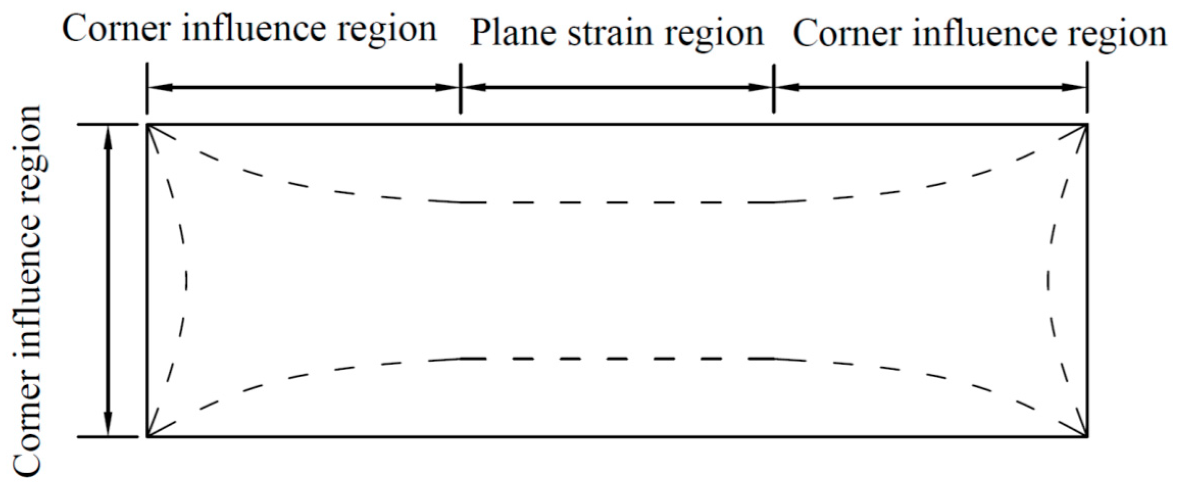
In the foundation pit design, the problem of the foundation pit is often simplified as a plane strain problem. However, in practical engineering, the deformation of the foundation pit presents an obvious spatial effect. As shown in Figure 3, due to the different stiffness of the support structure system and stress state of the soil, the deformation of the area close to the corner of the foundation pit is small, while the deformation of the central area of the longer retaining structure is large, which is similar to the deformation under the plane strain condition. Ou et al. [28] introduced the ratio of plane strain (PSR) to quantitatively describe the influence of the space effect, which is the ratio of displacements of soil mass or retaining structure under a three-dimensional simulation to the displacements under plane strain. Liu et al. [29] studied the spatial effect of the inner bracing foundation pit with different retaining structures. The results showed that the PSR variation trend of the underground diaphragm wall retaining structure was similar to the fitting formula curve proposed by Finno et al. [30]. When the PSR is close to 1.00, the value of the corresponding λ/He ratio is 4.00, and the PSR near the corner is 0.72. By substituting this into the fitting formula, the following equation can be obtained:
PSR ( λ , H e ) = 1.671 e 0.1 λ / H e ( 0 λ < 4 H e ) PSR ( λ , H e ) = 1 ( λ 4 H e ) }
By integrating Equations (1)–(3), the calculation formula of the retaining structure’s deformation increment at any position of the sidewall during the excavation of each layer after considering the spatial effect can be obtained:
δ i ( λ , η , H e i ) = PSR ( λ , H e i ) δ i ( η , H e i )
When the nth layers are excavated in the foundation pit, and the depth of the excavation face reaches He, the cumulative deformation distribution of the retaining structure is as follows:
v ( λ , η ) = i = 1 n δ i ( λ , η , H e i )
where the excavation depth of the foundation pit is the sum of the thickness of each layer excavated before, H e = H e 1 + i = 2 n ( H e i H e ( i 1 ) ) .
In terms of the theoretical calculation of earth pressure, some researchers in China have given a variety of approximate calculation methods for active earth pressure considering displacement, among which the expression of the tangent function to simulate the relationship between the relaxation stress and displacement proposed by Xu [31] is relatively simple, which is suitable to the simplified calculation of soil pressure on a retaining structure. Based on this theory, the calculation formula of the soil pressure at any point outside the retaining structure can be obtained as follows:
e a ( λ , η ) = e 0 ( λ , η ) + sin ( π 2 v ( λ , η ) v a c r ) [ e a c r ( λ , η ) e 0 ( λ ,   η ) ]
where e 0 ( λ , η ) and e a c r ( λ , η ) are the static earth pressure and active earth pressure under the limit state, respectively, obtained from the distribution of the soil layer outside the foundation pit, and vacr is the displacement required when the soil is in the active limit state, generally taking vacr = 0.001~0.003 H [32]. The unloading of the foundation pit sidewall can be considered as the difference between the static earth pressure at the initial state and the retaining structure’s lateral load after excavation. Therefore, the unloading of the sidewall can be expressed as
p c ( λ , η ) = e 0 ( λ , η ) e a ( λ , η ) = sin ( π 2 v ( λ , η ) v a c r ) [ e 0 ( λ ,   η ) e a c r ( λ , η ) ]

3. Additional Stress Distribution Caused by the Excavation of the Foundation Pit

3.1. Numerical Model and the Area Division of the Unloading Impact

The theoretical model for calculation is shown in Figure 4a,b. The rectangular foundation pit is excavated by the side of the shield tunnel, in which the serial numbers of the four sidewalls are ①, ②, ③ and ④. Let us establish a coordinate system at the center o of the foundation pit on the ground. The x-axis and y-axis are perpendicular and parallel to the tunnel axis, respectively, and the positive direction of the z-axis is vertically downward. The excavation size along the y-axis is L, the excavation size along the x-axis is B, and the excavation depth of the foundation pit is He. The horizontal distance between the axis of the tunnel and the center of the foundation pit is a, the outer diameter of the shield tunnel is D, the buried depth of the tunnel’s axis is h, and the minimum clearance between the retaining structure and the tunnel is s (s = aB/2 − D/2). The height of the retaining structure within the scope of deformation is H. Therefore, it can be ascertained that the coordinate of any point on the tunnel axis is (a, l, h), where l is the horizontal distance between the calculation point on the tunnel along the y-axis and the excavation center of the foundation pit.
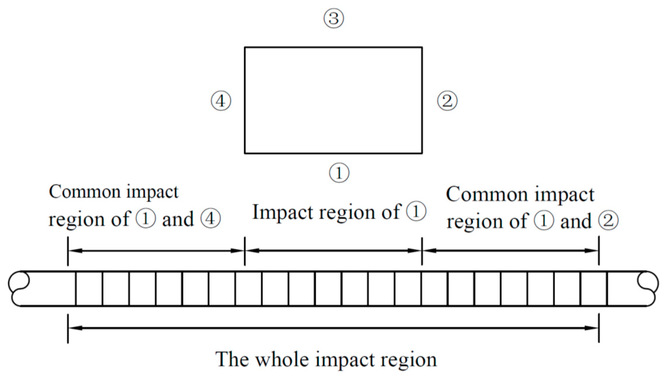
According to the analysis, the interval between foundation pit sidewall ③ and the tunnel is an open space in which the soil has been removed, so the unloading effect of sidewall ③ cannot be passed to the tunnel. Thus, this paper only considered the unloading effect of sidewalls ①, ② and ④ when calculating the additional stress on the tunnel. Meanwhile, this paper divided the impact region on the tunnel, which was affected by the unloading of each sidewall. As shown in Figure 5, the whole impact region can be divided into three parts. The central area of the whole impact region is mainly affected by the unloading of sidewall ①. The left side of the whole impact region is affected by the common impact of sidewalls ① and ④. The right side of the whole impact region is affected by the common impact of sidewalls ① and ②.

3.2. Calculation of Additional Stress Caused by Sidewall Unloading of the Foundation Pit

Based on the Mindlin stress solution of calculating horizontal load [33], by taking an infinitesimal element dζdη at point (B/2, ζ, η) on sidewall ①, the unloading effect on the soil mass is pc(L/2 − ζ, η)dζdη. Thus, if the equation about the unloading effect in the distribution area of sidewall ① is integrated, then the horizontal additional stress at any point (a, l, h) on the tunnel axis caused by the unloading of sidewall ① is taken as
σ x 1 ( l ) = ( a - B / 2 ) 8 π ( 1 μ ) 0 d L / 2 L / 2 p c ( L / 2 ζ , η ) { 1 2 μ M 1 3 ( 1 2 μ ) ( 5 4 μ ) N 1 3 + 3 ( a - B / 2 ) 2 M 1 5 + 3 ( 3 4 μ ) ( a - B / 2 ) 2 N 1 5 + 4 ( 1 μ ) ( 1 2 μ ) N 1 ( N 1 + h + η ) 2 [ 3 ( a - B / 2 ) 2 ( 3 N 1 + h + η ) N 1 2 ( N 1 + h + η ) ] 6 η N 1 5 [ 3 η ( 3 2 μ ) ( h + η ) + 5 ( a - B / 2 ) 2 h N 1 2 ] } d ζ d η
where M 1 = ( a B / 2 ) 2 + ( l ζ ) 2 + ( h η ) 2 ; N 1 = ( a B / 2 ) 2 + ( l ζ ) 2 + ( h + η ) 2 ; and μ is the Poisson ratio of the soil.
Taking an infinitesimal element dζdη at point (ξ, −L/2, η) on the sidewall (②), the unloading effect on the soil mass is pc(B/2 − ξ, η)dξdη. Thus, by integrating the equation about the unloading effect in the distribution area of the sidewall (②), the horizontal additional stress at any point (a, l, h) on the tunnel axis caused by the unloading of the sidewall (②) is taken as
σ x 2 ( l ) = ( l + L / 2 ) 8 π ( 1 μ ) 0 d B / 2 B / 2 p c ( B / 2 ζ , η ) { 1 2 μ M 2 3 ( 1 2 μ ) ( 3 4 μ ) N 2 3 + 3 ( a ξ ) 2 M 2 5 + 3 ( 3 4 μ ) ( a ξ ) 2 N 2 5 + 4 ( 1 μ ) ( 1 2 μ ) N 2 ( N 2 + h + η ) 2 [ 1 ( a ξ ) 2 ( 3 N 2 + h + η ) N 2 2 ( N 2 + h + η ) ] 6 η N 2 5 [ η ( 1 2 μ ) ( h + η ) + 5 ( a ξ ) 2 h N 2 2 ] } d ξ d η
where M 2 = ( a ξ ) 2 + ( l + L / 2 ) 2 + ( h η ) 2 and N 2 = ( a ξ ) 2 + ( l + L / 2 ) 2 + ( h + η ) 2 .
Similarly, the horizontal additional stress at any point (a, l, h) on the tunnel axis caused by the unloading of the sidewall (④) is taken as
σ x 4 ( l ) = ( l L / 2 ) 8 π ( 1 μ ) 0 d B / 2 B / 2 p c ( B / 2 ζ , η ) { 1 2 μ M 4 3 ( 1 2 μ ) ( 3 4 μ ) N 4 3 + 3 ( a ξ ) 2 M 4 5 + 3 ( 3 4 μ ) ( a ξ ) 2 N 4 5 + 4 ( 1 μ ) ( 1 2 μ ) N 4 ( N 4 + h + η ) 2 [ 1 ( a ξ ) 2 ( 3 N 4 + h + η ) N 4 2 ( N 4 + h + η ) ] 6 η N 4 5 [ η ( 1 2 μ ) ( h + η ) + 5 ( a ξ ) 2 h N 4 2 ] } d ξ d η
where M 4 = ( a ξ ) 2 + ( l L / 2 ) 2 + ( h η ) 2 and N 4 = ( a ξ ) 2 + ( l L / 2 ) 2 + ( h + η ) 2 .
According to the impact region division mentioned above, superposing of the unloading effect of the three sidewalls occurs. Therefore, the distribution of the horizontal additional load caused by foundation pit excavation along the axis of the adjacent shield tunnel can be expressed as
P ax ( l ) = σ x 1 ( l ) + σ x 2 ( l ) l ( , L / 2 ] P ax ( l ) = σ x 1 ( l ) l ( L / 2 , L / 2 ) P ax ( l ) = σ x 1 ( l ) + σ x 4 ( l ) l [ L / 2 , + ) }

4. Longitudinal Deformation of the Shield Tunnel by the Side of the Foundation Pit

This paper introduced a collaborative deformation model that comprehensively considers the deformation effects of rotation and dislocation of the shield tunnel segments [34].

4.1. Collaborative Deformation Mode of the Shield Tunnel with Rotation and Dislocation

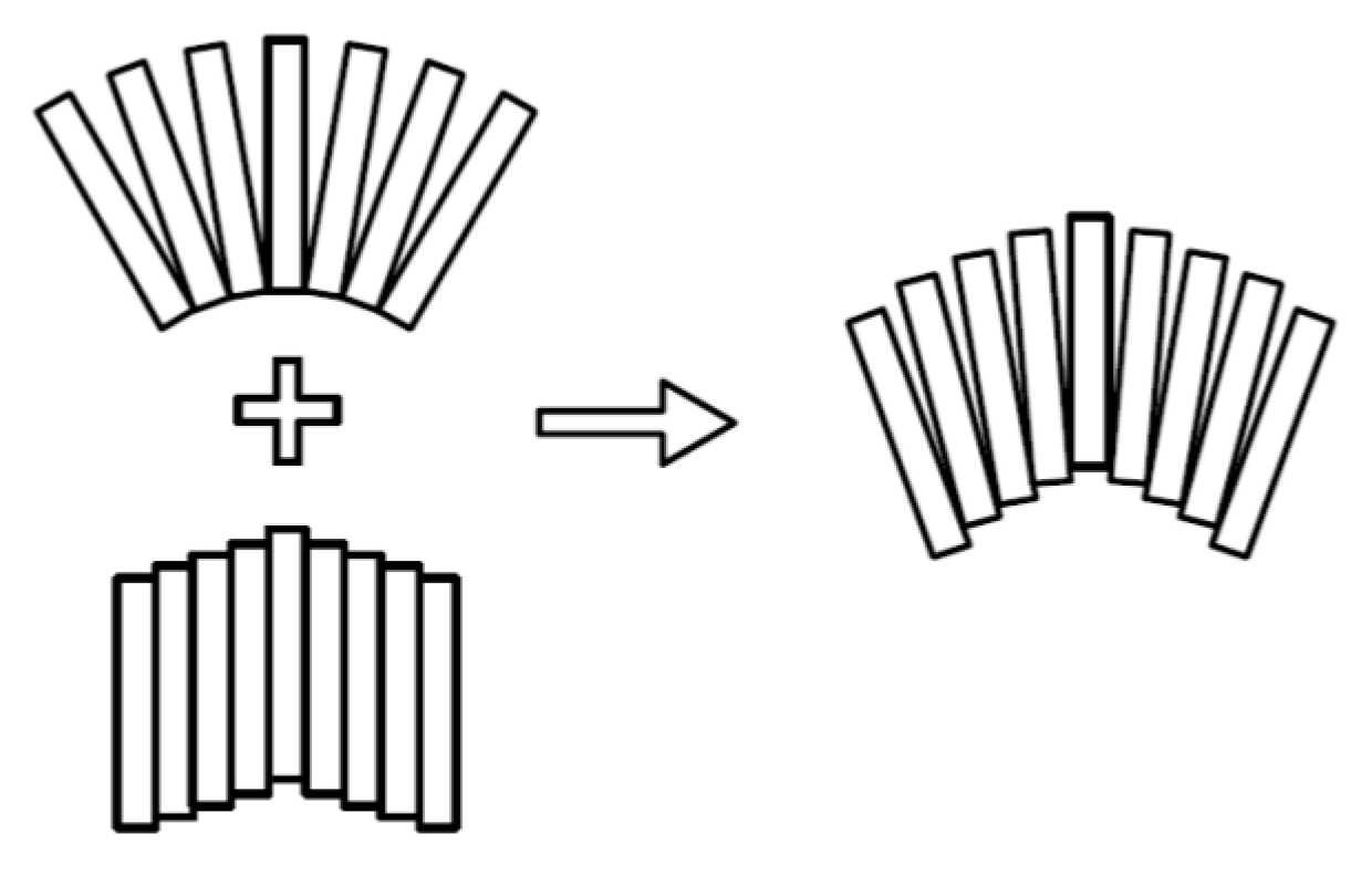
As shown in Figure 6, each section of the segment ring of the shield tunnel was simplified as a short beam on an elastic foundation, and the segment ring was connected by a normal spring and a shear spring. Relative rotation and relative dislocation would occur between adjacent segments. The longitudinal deformation of the tunnel was considered to be formed by combining the shear dislocation and rigid body rotation between adjacent segments.
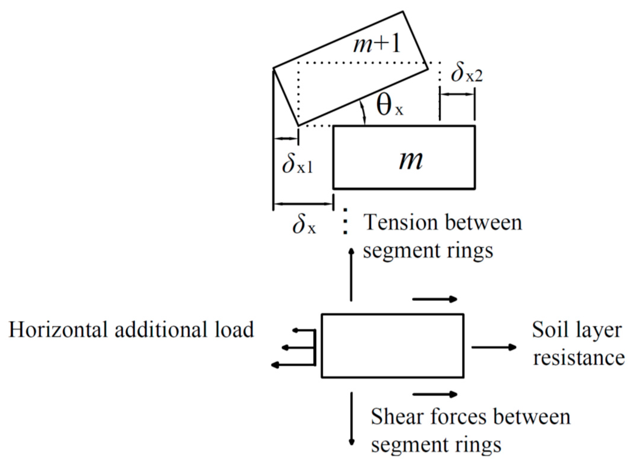
As shown in Figure 7, when the total relative horizontal displacement between the adjacent ring segments numbered m and m + 1 was δx, the relative horizontal displacement induced by the rigid rotation of the segment rings was δx1, the relative horizontal displacement generated by the dislocation of the segment rings was δx2 and the rotation angle between the segment rings was θx. This satisfied the equation δx = δx1 + δx2. Let us set δx1 = jxδx, where jx is the proportionality coefficient for the rotation effects of the segment rings with the horizontal displacement of the tunnel axis (i.e., the ratio of the relative horizontal displacement generated by the rotation between adjacent segment rings to the total relative horizontal displacement). When jx = 0, there is no relative rotation between adjacent segment rings, which is the deformation mode of complete shear dislocation. This is consistent with the deformation model of dislocation proposed by Zhou et al. [22]. When jx = 1, the horizontal displacement is completely caused by the rotation of adjacent segments, which is the deformation mode of complete rotation. According to the research in previous studies [34], the value of the proportionality coefficient jx is 0.1~0.3, and it can be assumed that jx = 0.2 in this study.
Assuming that the shield tunnel by the side of the foundation pit meets the condition of deformation coordination with the surrounding soil, the displacement of the tunnel is equal to that of the soil at the corresponding position:
u ( l ) = u t ( l )
where l is the calculated position in the longitudinal direction of the tunnel, taking the center of the foundation pit’s excavation as a zero point which is positive along the y-axis; u(l) is the horizontal displacement distribution of the shield tunnel by the side of the foundation pit; and ut(l) is the horizontal displacement of the soil around the tunnel along the tunnel axis.
The difference between the horizontal displacement values of the adjacent segments is the relative horizontal displacement of the adjacent segment rings. Thus, the horizontal displacement between the rings can be expressed as
δ x = u ( ( m + 1 ) D t ) u ( m D t ) = u t ( ( m + 1 ) D t ) u t ( m D t )
where the serial numbers of the adjacent segment rings are m and m + 1, and Dt is the width of the segment ring.
When the rotation angle θx between the segment rings is low, it can be assumed that sin (θx) = θx and cos (θx) = 1. Therefore, the calculation formula for the horizontal displacement caused by rotation between the segment rings is
δ x 1 = D t θ x
By substituting δx1 = jxδx into Equation (14), it is easy to get
θ x = j x δ x D t
According to tunnel deformation, the shear stiffness and tensile stiffness between the rings, the foundation reaction coefficient and the shear force between the rings can be obtained as follows
Q x = k sl δ x 2 =   ( 1 j x )   k sl δ x
The maximum tension between rings is
F tx = k t θ x D
The strata resistance is
F kx = k D u t ( l ) = k D u ( l )
In Equations (16) and (17), ksl and kt are the shear stiffness and tensile stiffness between the rings of the tunnel, respectively, and the value method can be referred to in [35]. In Equation (18), Vesic’s formula [36] is used to calculate k, which is the foundation reaction coefficient. k = 0.65 E 0 ( 1 μ 2 ) D E 0 D 4 ( E I ) eq 12 , where μ is the Poisson ratio of the soil. E0 is the deformation modulus of the foundation soil. E 0 = ( 1 + μ ) ( 1 2 μ ) ( 1 μ ) E s , where Es is the compression modulus of soil. (EI)eq is the equivalent flexural stiffness of the tunnel. According to the research of Ye et al. [37], the equivalent stiffness of the shield tunnel can be calculated according to the following formula:
( E I ) eq = E c λ 1 + n D t K b λ 2 A s
where Ec is the elastic modulus of the segment; n is the number of longitudinal bolts; Dt is the width of the segment rings; Kb is the average linear stiffness of the joint bolt; and As is the cross-sectional area of the tunnel. When the horizontal diameter and vertical diameter of the tunnel are not considered to change, λ 1 = t D ( A 1 + A 2 A 3 A 4 A 5 ) ; λ 2 = t D ( A 1 + A 2 + A 3 + A 4 + A 5 ) ; A 1 = π D 2 / 16 ; A 2 = π D 2 sin 2 ψ / 8 ; A 3 = D 2 ψ / 8 ; A 4 = D 2 ψ sin 2 ψ / 4 ; and A 5 = 3 D 2 sin ψ cos ψ / 8 . Among this, ψ is the location parameter of the segment ring’s central axis, which assumes ψ = 30° in this study, and the determination methods can be referenced in [37]. t is the thickness of the segment, and D is the outside diameter of the tunnel.

4.2. The Total Potential Energy of the Shield Tunnel during Deformation

According to the procedure analysis of the longitudinal deformation of the shield tunnel, the total potential energy of the shield tunnel during deformation can be specifically composed of the following four parts:
(1)
Work done by the horizontal additional load caused by the excavation of the foundation pit:
W L = m = N N 1 m D t ( m + 1 ) D t u ( l ) P ax ( l ) d l = N D t N D t u ( l ) P ax ( l ) d l
where Pax(l) is the horizontal additional load caused by foundation pit excavation along the axis of the adjacent shield tunnel, which can be obtained with Equation (11), and N is the number of shield tunnel segment rings within the calculation range. The value taken in this paper’s calculation should be related to the range affected by the excavation of the foundation pit by the side of the shield tunnel. Theoretically, the greater the value of N is, the higher the calculation accuracy will be. However, the corresponding calculation amount will also increase, and the calculation efficiency will be affected. In order to ensure the accuracy of the calculation, the length of the tunnel included in the calculation range should not be less than the scope of the tunnel affected by the foundation pit. According to previous research [25], many factors influence the length of the impact region, and the excavation size of the foundation pit parallel to tunnel (L) is the main factor, and the impact region is about 2~3 times the size of L. Therefore, in the initial calculation, the value of N should not be less than 1.5 L/Dt, where Dt is the width of the segment ring. According to the method proposed in previous studies [34], if it is found that the influence range is large, the value of N should be increased appropriately until the calculated value tends to be stable.
(2)
Work done by overcoming the soil layer resistance:
W R = m = N N 1 m D t ( m + 1 ) D t 1 2 u ( l ) k D u ( l ) d l = N D t N D t 1 2 k D [ u ( l ) ] 2 d l
(3)
Work done by overcoming the shear forces between the rings:
W S = m = N N 1 1 2 Q x δ x 2 = m = N N 1 1 2 k sl ( 1 - j x ) 2 δ x 2
(4)
Work done by overcoming the tension caused by rotation between the rings:
W T = m = N N 1 ( r = 0 r = D 1 2 k t D θ x 2 r 2 d r ) = m = N N 1 k t θ x 2 D 2 6
where r is the integral variable, which represents the distance from the calculated point at the segment joint to the bottom of the tunnel. The rotation angle between the segment rings can be obtained through θ x = j x δ x D t = j x [ u ( ( m + 1 ) D t ) u ( m D t ) ] D t .
Therefore, it can be ascertained that
W T = m = N N 1 k t j x 2 D 2 6 D t 2 [ u ( ( m + 1 ) D t ) u ( m D t ) ] 2
The total potential energy of deformation of the shield tunnel by the side of the foundation pit is
E p = W L + W R + W S + W T

4.3. Fourier Expansion of the Curve Function of the Shield Tunnel’s Horizontal Displacement

In this paper, the distribution of the excavation area in the simplified model is parallel to that of the adjacent shield tunnel. Theoretically, the longitudinal deformation of the shield tunnel should be symmetrical about the middle point of the foundation pit’s excavation. Therefore, a Fourier series expansion can be performed according to the cosine function to obtain
u ( l ) = n = 0 a n cos n π l N D t = T n ( l ) A T
where n is the number of terms in the Fourier series; an is the Fourier expanding coefficients for each term; T n ( l ) = ( 1   cos π l N D t   cos 2 π l N D t     cos n π l N D t ) ; and A = ( a 0   a 1   a 2     a n ) T .

4.4. Solve the Variational Control Equation

Based on the principle of minimum potential energy, the total potential energy Ep takes the extremum of each undetermined coefficient. In other words,
E p a i = W L a i + W R a i + W S a i + W T a i = 0 ( i = 0 , 1 , 2 n )
where ai is the ith element in matrix A (i.e., the coefficient of the polynomial of the tunnel deformation curve function).
The control equation can be obtained by solving the above equation:
N D t N D t P ax ( l ) { T n ( l ) } T d l = { m = N N 1 [ ( k sl ( 1 - j x ) 2 + k t j x 2 D 2 3 D t 2 ) ( u ( ( m + 1 ) D t ) u ( m D t ) ) a i ( T n ( ( m + 1 ) D t ) T n ( m D t ) ) ] + N D t N D t k D u ( l ) a i T n ( l ) d l } × A T
The above expressions can be abbreviated in matrix form:
( [ K r ] + [ K s ] ) A T = [ P ax ] T
where [Kr]AT is the interaction effect between tunnel rings:
[ K r ] = m = N N 1 [ ( k sl ( 1 - j x ) 2 + k t j x 2 D 2 3 D t 2 ) ( T n ( ( m + 1 ) D t ) T T n ( m D t ) T ) ( T n ( ( m + 1 ) D t ) T n ( m D t ) ) ]
[Ks]AT is the effect of the soil resistance:
[ K s ] = k D N D t [ 2 1 1 1 ]
[Pax]T represents the effect of additional load on the tunnel lining:
[ P ax ] T = N D t N D t P ax ( l ) { T n ( l ) } T d l  
According to Equation (29), the undetermined coefficient matrix AT can be obtained:
A T = ( [ K r ] + [ K s ] ) 1 [ P ax ] T
Substituting the undetermined coefficient matrix AT back into Equation (26) reveals the distribution function of the horizontal displacement along the tunnel axis beside the foundation pit:
u ( l ) = T n ( l ) A T
Thus, the dislocation quantity between adjacent segments of the shield tunnel caused by longitudinal deformation of the tunnel can be obtained as follows:
δ x 2 = ( 1 j x ) [ u ( ( m + 1 ) D t ) u ( m D t ) ]
Then, the shear force Qx between adjacent segments of the shield tunnel is
Q x = ( 1 j x ) [ u ( ( m + 1 ) D t ) u ( m D t ) ] × k sl

5. Engineering Case Analysis

Since the longitudinal deformation of the adjacent existing shield tunnel caused by the excavation of the foundation pit is mainly horizontal displacement, this paper selected two engineering cases of the foundation pit and used the method derived previously to calculate the horizontal displacement curve of the shield tunnel axis caused by the excavation of an adjacent foundation pit, then compared it with the measured curve so as to prove the reliability of this method.

5.1. Case History 1

Take the deep foundation pit project by the side of the shield tunnel of Hangzhou Metro Line 2 as a case study, which has been put into operation at the intersection of Shixinzhong Road and Jincheng Road in the Xiaoshan District. The plane size of the foundation pit excavation was L = 68 m, B = 72 m, with the excavation depth He = 15.8 m, and the underground diaphragm wall was 37.2 m below the ground. The minimum clearance from the sideline of the foundation pit’s retaining structure to the tunnel was s = 9.5 m [38]. The outer diameter of the shield tunnel was D = 6.2 m, which adopted C50 concrete segments. The thickness of the segments was t = 0.35 m, and the ring width was Dt = 1.2 m. Sixteen M30 longitudinal bolts were used to connect the adjacent segment rings. According to the calculation, ksl = 2.23 × 10⁶ kN/m, kt = 9.39 × 10⁵ kN/m and (EI)eq = 1.1 × 10⁸ kN·m2. The tunnel was buried 14.3 m deep in the silty silt and sandy silt layer. In the excavation scope of the foundation pit, the main distribution of the soil was miscellaneous fill, silty clay, sandy silty soil and silty sand with silty soil. According to the actual engineering geological conditions, the value of the soil weight chosen weighted a mean of γ = 18.4 kN/m3, and the Poisson’s ratio of the soil was μ = 0.4. In the process of the foundation pit’s excavation, this case was divided into four soil layers and excavated layer by layer, with the thickness of each layer from top to bottom being 1.6 m, 4.9 m, 4.8 m and 4.5 m, respectively.
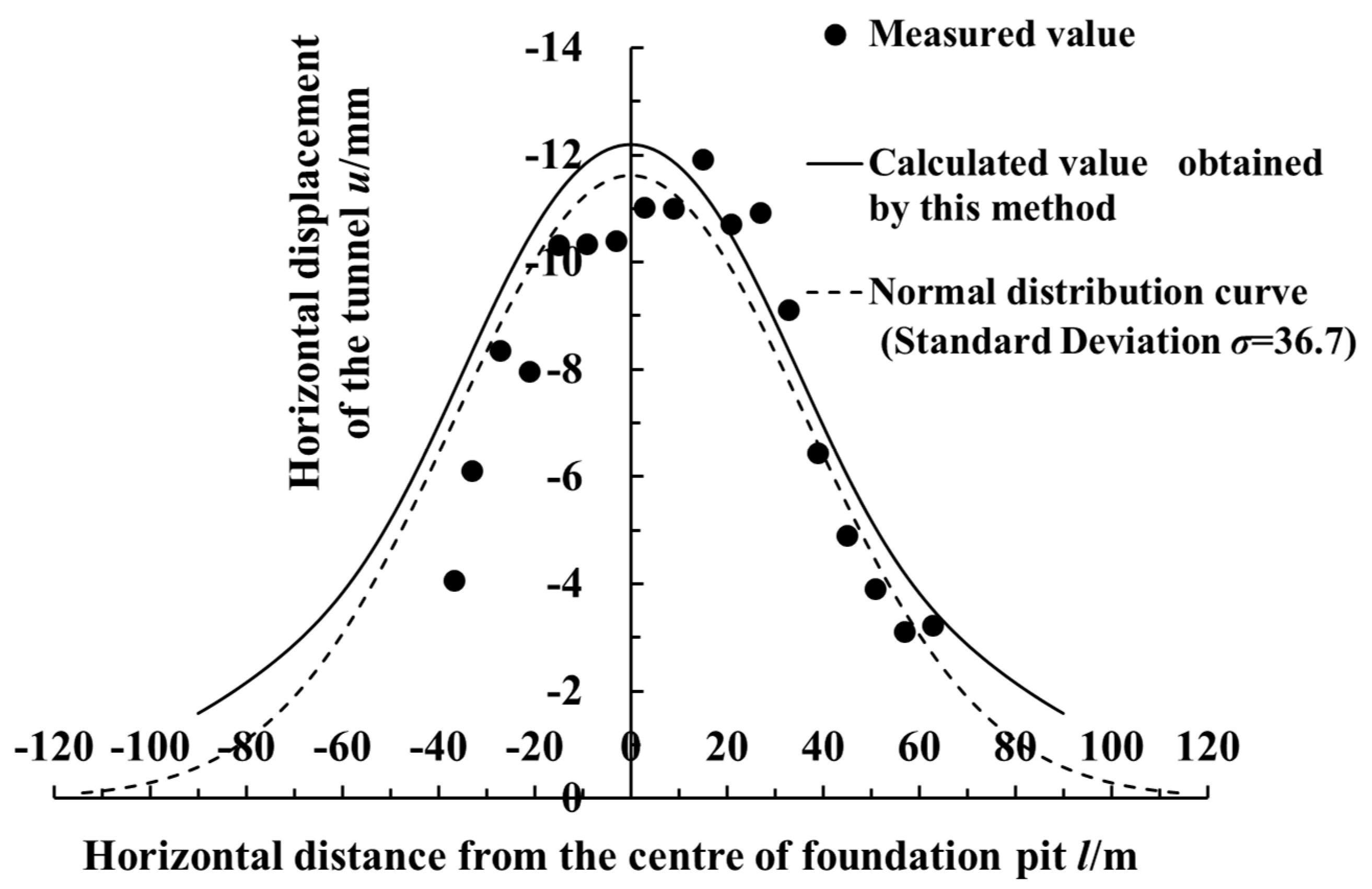
Figure 8 compares the measured data with the calculated data of the horizontal displacement values of the shield tunnel by the side of the foundation pit. As shown in the figure, the calculation results and measured results were basically consistent, and the deformation control parameter of the retaining structure in this case’s calculation was vmax/He = 0.2% (i.e., the accumulated maximum deformation after the excavation of each soil layer was 0.2% of the excavation depth under such condition). The accumulated maximum deformation of the sidewall retaining structure in this case was within 31.6 mm. At this time, the rotation effects proportionality coefficient of the shield tunnel was jx = 0.2 (i.e., the horizontal deformation caused by the relative rotation of the segment rings accounted for 20%, while the horizontal deformation caused by the dislocation of the segment rings accounted for 80%). It can be seen from the figure that the value of horizontal displacement was mainly negative, indicating the displacement of the shield tunnel was along the negative direction of x-axis (toward the side of the foundation pit). The maximum calculated value of the horizontal displacement was 12.20 mm, whereas the maximum measured value of the horizontal displacement was 11.90 mm. The horizontal displacement of the tunnel was normally distributed, and the horizontal displacement was large near the center of foundation pit, while the two sides decreased successively.
Figure 9 shows the calculated curves of the adjacent shield tunnel’s horizontal displacement caused by the unloading of each sidewall, and the partition of the region affected by the unloading of each sidewall is shown in Figure 5. It can be seen from Figure 9 that tunnel’s horizontal displacement of the total longitudinal deformation was mainly caused by the unloading effect of sidewall ①, while the unloading effects of sidewalls ② and ④ had little influence on the adjacent tunnel. The unloading effect of sidewall ① was mainly concentrated near the excavation center, and its influence range was approximately within 120 m of both sides of the excavation center. The maximum horizontal displacement caused by it was 11.89 mm, which was located in the excavation center and closed to the total deformation of the tunnel. The unloading effects of sidewalls ② and ④ had little contribution to the horizontal displacement of the tunnel near the excavation center. Its main influence range was 15~125 m from the excavation center. The horizontal displacement caused by the unloading effect of sidewalls ② and ④ reached its peak value at about 60 m away from the excavation center, but it was merely 1.01 mm.
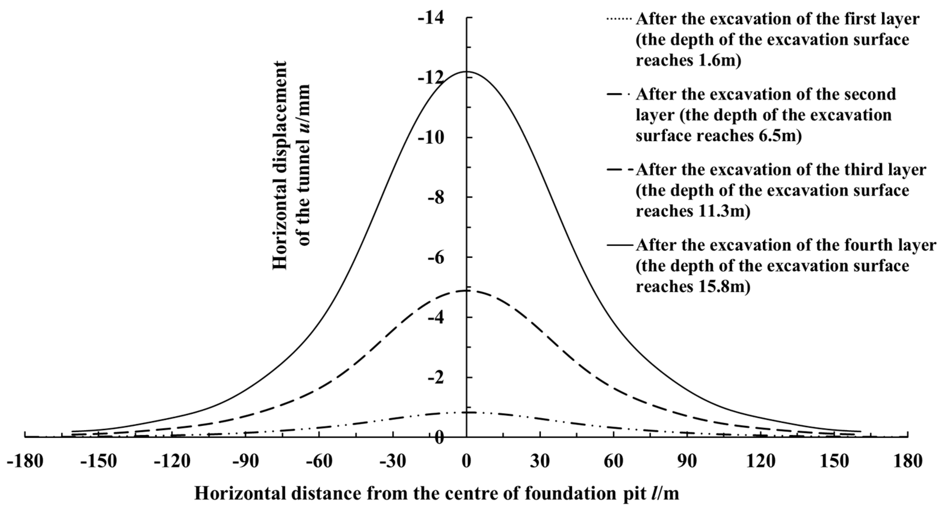
Figure 10 presents the calculated curves of the adjacent shield tunnel’s horizontal displacement after the excavation of each soil layer in the foundation pit during the process of layer-by-layer excavation. It can be seen from the figure that there was little impact on the adjacent shield tunnel, as the excavation thickness of the first layer was small, being only 1.6 m. The excavation thickness of the second floor was 4.9 m, and the depth of the excavation surface reached 6.5 m after completion of excavation. The adjacent shield tunnel began to show a small amount of horizontal displacement, and the maximum horizontal displacement was only 0.83 mm, which still impacted the shield tunnel a little. The excavation thickness of the third layer was 4.8 m, and the depth of the excavation surface reached 11.3 m after excavation was completed. At this time, the accumulated thickness of the excavated soil layer was equivalent to the thickness of the overlying layer on the adjacent shield tunnel, and the shield tunnel began to show relatively obvious longitudinal deformation, with the maximum horizontal displacement reaching 4.88 mm. After the excavation of the fourth soil layer, whose thickness was 4.8 m, the excavation face reached the final depth of 15.8 m, which exceeded the buried depth of the tunnel axis. The horizontal displacement of the adjacent shield tunnel caused by the excavation of the foundation pit had increased dramatically. The maximum horizontal displacement in the vicinity of the excavation center was 12.20 mm, which was close to the final measured values. It can be seen that during the excavation of the foundation pit, the excavation of the deep soil layer had a greater impact on the adjacent shield tunnel, especially when the excavation depth was in the soil layer near the buried depth of the tunnel. The longitudinal deformation of the adjacent shield tunnel would increase sharply, so more attention should be paid to the deformation control of the tunnel in this working condition.
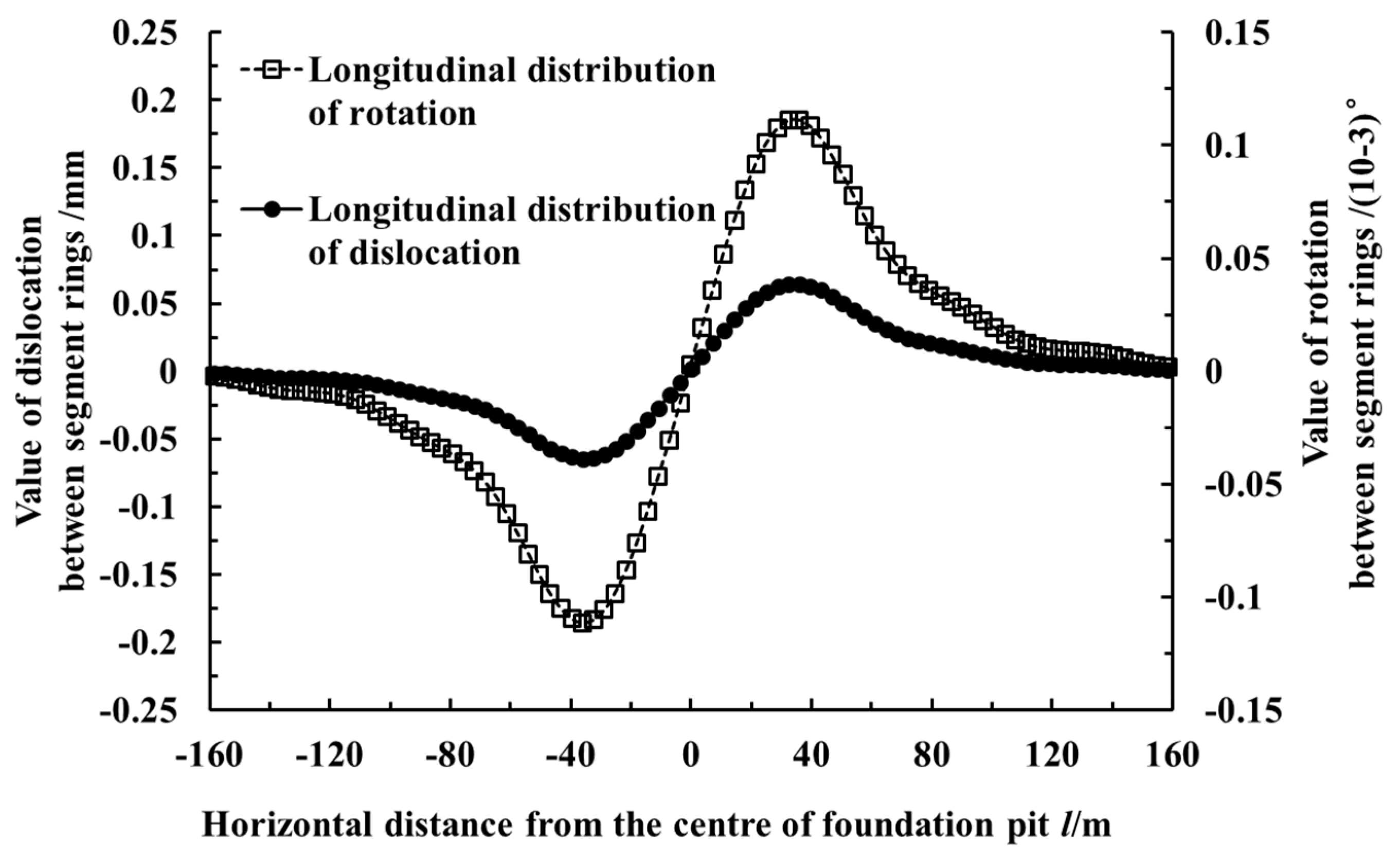
The values of the dislocation and rotation angle between the rings are important to the safety of the tunnel structure and waterproofing system. The greater the rotation angle between the rings, the greater the opening of the ring seam. The probability of leakage in the shield tunnel will be greatly increased when the values of the seam opening and dislocation between the rings are large. Therefore, it is necessary to estimate the value of the seam opening and dislocation between the rings. Figure 11 shows the calculated curves of the shield tunnel segment dislocation and rotation between the rings. As shown in the figure, the dislocation and rotation between the segment rings were close to 0 at the center of the foundation excavation. This means that there was almost no dislocation or rotational deformation between the segment rings near where the value of the shield tunnel’s horizontal displacement was at its maximum. The maximum segment dislocation was 0.19 mm, and the maximum rotation angle between the rings was 3.87 × 10⁻⁵ degrees. Both of them appear near the two inflexion points of the displacement curve in Figure 11, with a 36 m horizontal distance to the center of the foundation excavation.
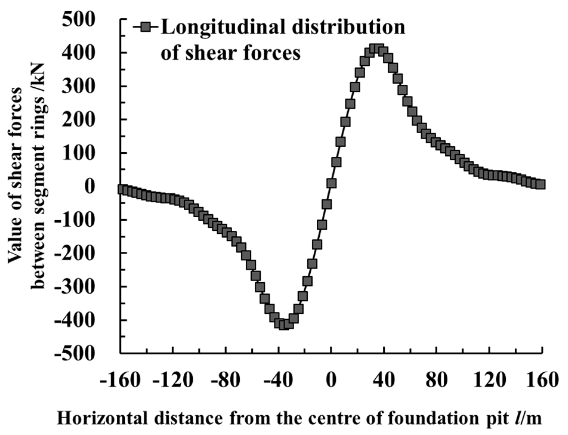
Figure 12 shows the value of the shear force between the segment rings of the shield tunnel by the side of the foundation pit, calculated by using the method presented in this paper. As shown in the figure, the variation law of shear force between the segment rings of the shield tunnel was consistent with the variation law of the dislocation. The maximum shear force was 414.87 kN, which occurred at the position with the maximum value of dislocation.

5.2. Case History 2

The plane size of the foundation pit excavation area was L = 70 m, B = 42 m, which was adjacent to Shanghai Metro Line 1 [39], with a 10 m excavation depth. Shanghai Metro Line 1 is located below the road by the side of the foundation pit, 7.2 m away from the retaining structure of the foundation pit, which can be simplified as a tunnel parallel to the northeast side’s retaining structure of the foundation pit. The outer diameter of the shield tunnel segment ring was D = 6.2 m, the ring width was Dt = 1 m and the segment thickness was t = 0.35 m. Sixteen M30 longitudinal bolts were used to connect the segment rings. According to the calculations, ksl = 2.23 × 10⁶ kN/m and kt = 9.39 × 10⁵ kN/m. The tunnel axis was buried 10.1 m deep and was located in the sandy silt and muddy clay layer. The soil layers in the excavation scope of the foundation pit mainly included filling soil, silty clay and sandy silty soil. According to the engineering geological conditions, the value of the soil weight took on a weighted mean γ = 18.2 kN/m3, and the Poisson’s ratio of the soil was μ = 0.35.
Figure 13 shows the curves which compared the calculated data of the horizontal displacement with the measured data. As shown in the figure, the calculated results were in good agreement with the measured results. At this time, the proportionality coefficient for the rotation effects of the adjacent shield tunnel was jx = 0.2 (i.e., the horizontal deformation caused by the rotation of the segment rings accounted for 20%, while the horizontal deformation caused by the dislocation of the segment rings accounted for 80%). In this case’s calculations, the control parameter of the retaining structure deformation was vmax/He = 0.15% (i.e., the accumulated maximum deformation after excavating each layer in the foundation pit was 0.15% of the excavation depth under this working condition). The accumulated maximum deformation of the sidewall retaining structure in this case was within 15 mm. It can be seen from the figure that the maximum horizontal displacement shown by the measured data was 3.66 mm. In contrast, the maximum horizontal displacement of the side shield tunnel calculated by the method in this paper was 4.04 mm. The horizontal displacement of the tunnel presented a normal distribution, and the tunnel’s horizontal displacement at the center of the excavation was large, while the two sides decreased successively.
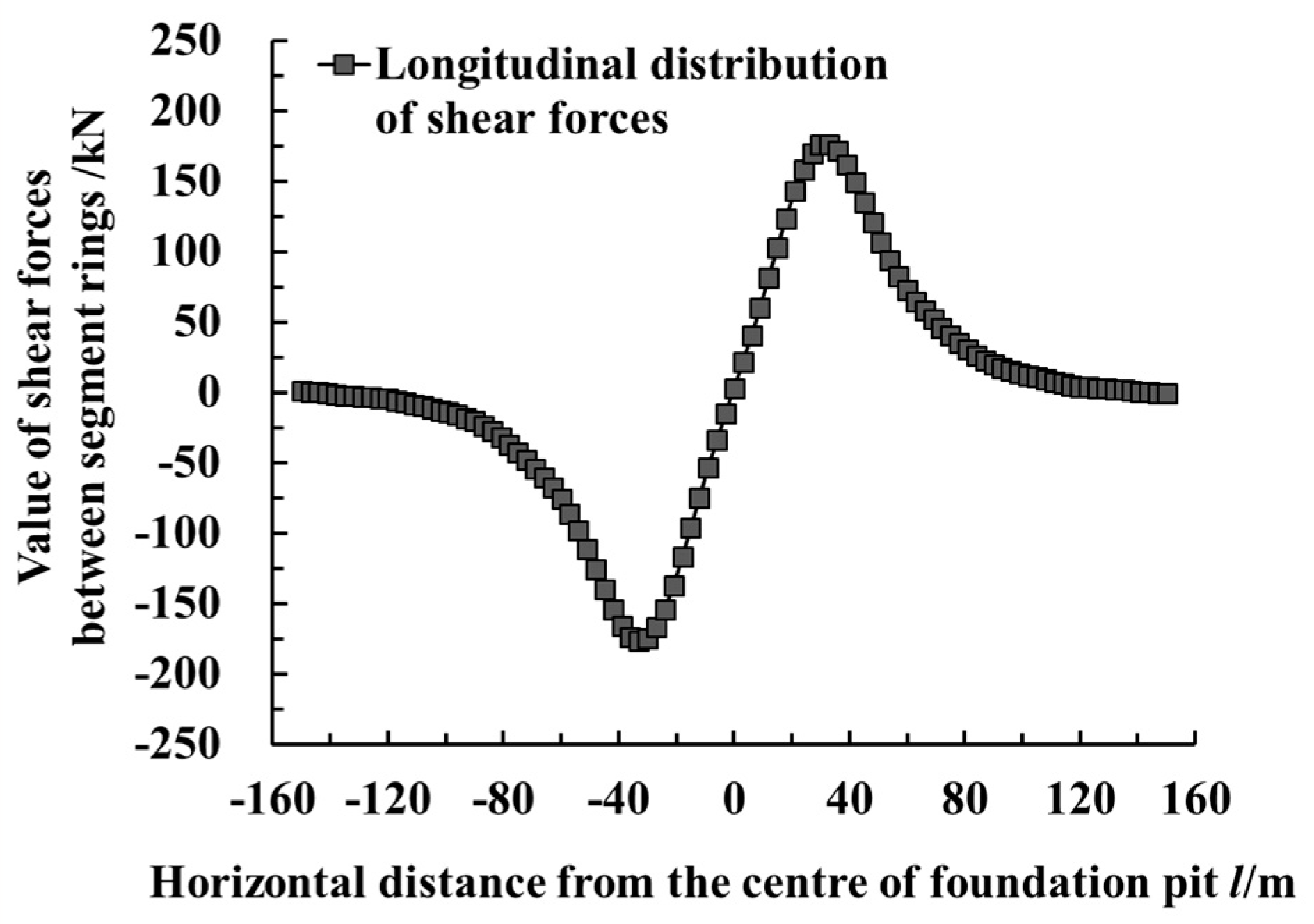
Figure 14 shows the longitudinal distribution curves of the calculated dislocation and rotation angle between the shield tunnel segment rings. As shown in the figure, the dislocation and rotation angle between the segment rings at the position of maximum horizontal displacement were basically equal to zero. The maximum dislocation and rotation angle between the rings occurred at the inflexion point of the horizontal displacement curve. The maximum values were 0.08 mm and 1.65 × 10⁻⁵ degrees, respectively. Figure 15 shows the distribution curve of the calculated shear force between the adjacent shield tunnel segment rings. As shown in the figure, the shear force between the adjacent segment rings was the largest at a horizontal distance of 33 m from the excavation center, with a maximum value of 176.66 kN.
Comparing Case 2 with Case 1, the length of the tunnel by the side of the excavation area was equal, but the excavation depth of the foundation pit in Case 2 was only about 60% that of Case 1. Meanwhile, the excavation width of Case 2 was also smaller. Thus, in Case 2, the deformation of the sidewall retaining structure was smaller, and the caused amount of sidewall unloading was relatively smaller, which means the value of the tunnel’s horizontal displacement was smaller. On the whole, the distribution rules of horizontal displacement, the rotation angle between the segment rings, dislocation and shear force between the segment rings of the shield tunnel were basically similar to those in Case 1.

6. Analyzing the Influence Factors of the Adjacent Tunnel’s Longitudinal Deformation

6.1. Deformation Control Parameters of the Foundation Pit Retaining Structure vmax/He

In engineering applications, the accumulated maximum deformation of the foundation pit’s retaining structure is usually taken as the deformation control parameter of the retaining structure. Statistics of the measured data [40,41,42] show that the cumulative maximum deformation of the retaining structure is closely related to the excavation depth. According to the statistics of Liao et al. [40], the variation range of the control parameter (vmax/He) of the underground diaphragm wall in Suzhou is between 0.05% and 0.40%, with an average value of 0.20%. According to the statistics of Wang et al. [41], the variation range of the control parameter (vmax/He) of the underground diaphragm wall in Hangzhou is between 0.09% and 0.32%, and the average value is 0.26%. Xu et al. [42] analyzed the measured data of 93 foundation pits in Shanghai which use underground diaphragm walls as retaining structures and found that the vmax/He was between 0.1% and 1.0%, with an average value of 0.42%.
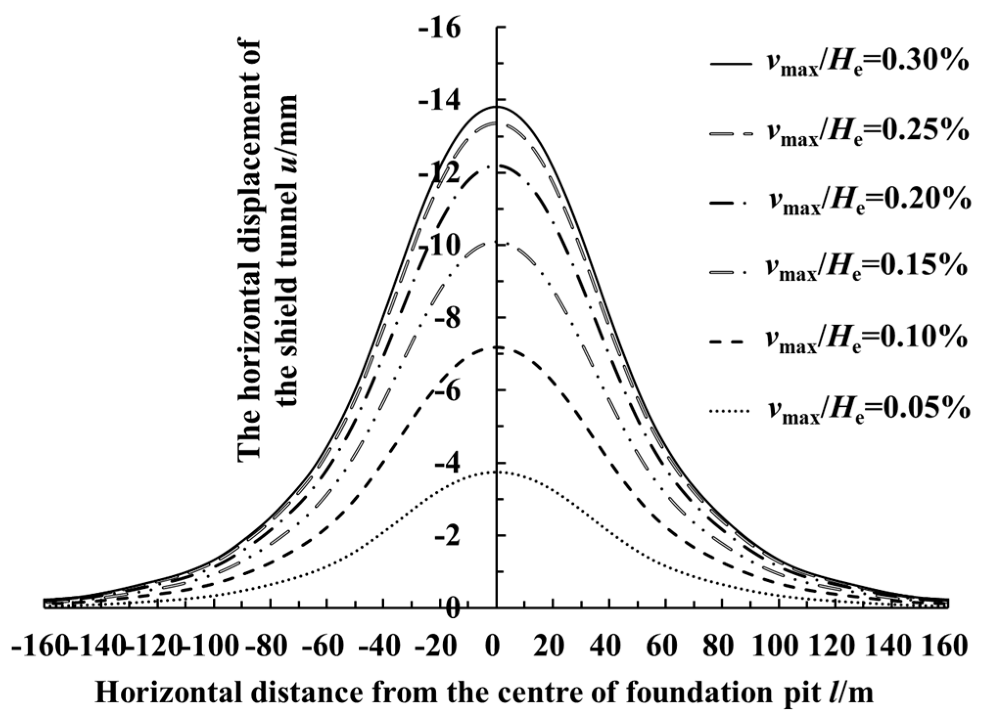
Taking Case History 1 in this paper as the basic working condition changed the deformation control parameter (vmax/He) of the foundation pit’s retaining structure under the condition that the other parameters remained constant. Figure 16 shows the curve of the maximum calculated value of the horizontal displacement of the shield tunnel by the side of the foundation pit changing with the deformation control parameter (vmax/He) of the retaining structure. As shown in the figure, when vmax/He = 0.25%, the maximum horizontal displacement of the shield tunnel adjacent to the foundation pit reached 13.37 mm. When vmax/He increased to 0.30%, the deformation of the retaining structure in this numerical example was controlled within 47.4 mm. At this time, the horizontal displacement distribution of the shield tunnel already changed a little, with a maximum increment of horizontal displacement of about 0.5 mm. This was because the soil mass at the maximum deformation of the retaining structure was close to the limit state. The deformation of the retaining structure continued to increase, while the increase of the sidewall unloading was not obvious. Figure 17 shows the longitudinal distribution curve of the calculated horizontal displacement value of the shield tunnel by the side of the foundation pit when the deformation control parameter vmax/He was taken as 0.05%, 0.10%, 0.15%, 0.20%, 0.25% and 0.30%, respectively. As shown in the figure, when vmax/He = 0.05%, the deformation of the retaining structure in this calculation was controlled within 7.9 mm. Meanwhile, the horizontal displacement of the shield tunnel by the side of the foundation pit was small, with a maximum horizontal displacement of 3.74 mm. With the increase of the deformation control parameter (vmax/He) of the retaining structure, the shield tunnel’s horizontal displacement value and the influence range of longitudinal deformation also increased.

6.2. The Clearance s between the Foundation Pit and the Tunnel

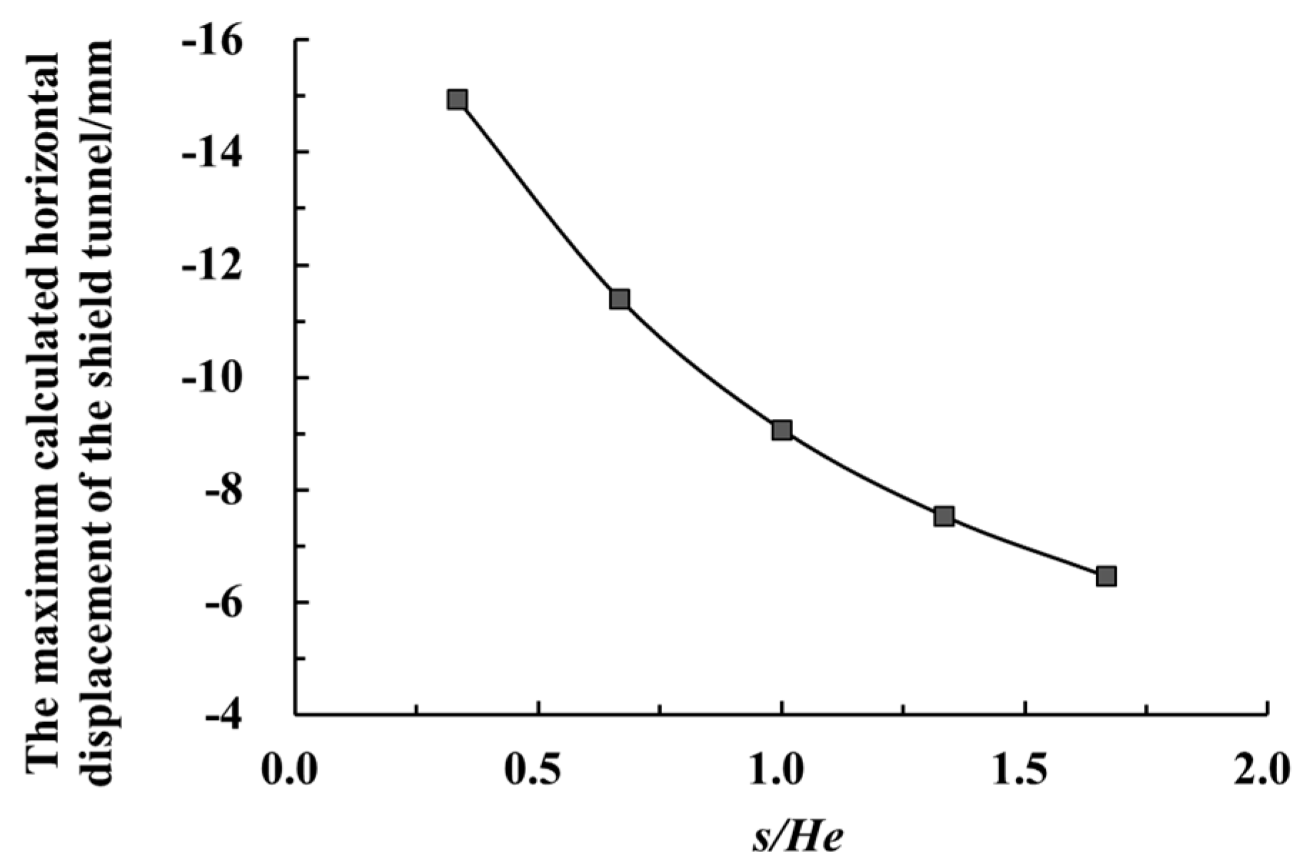
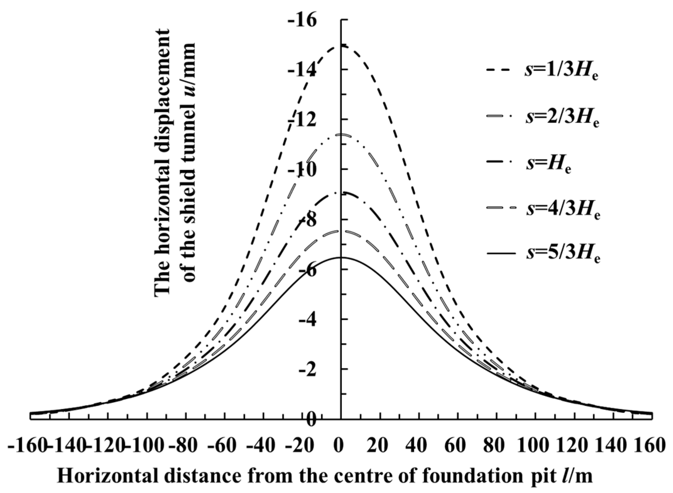
Let us take Case History 1 in this paper as the basic working condition, under the condition that the other parameters remained constant and only changing the clearance s between the foundation pit and the adjacent tunnel. Figure 18 shows the maximum calculated horizontal displacement of the shield tunnel by the side of the foundation pit, which changed with the ratio of clearance s to the excavation depth He. Figure 19 shows the longitudinal distribution curve of the calculated horizontal displacement value of the shield tunnel by the side of the foundation pit when clearance s equaled 1/3 He, 2/3 He, He, 4/3 He, 5/3 He, respectively. As shown in Figure 18 and Figure 19, with the increase of the clearance s, the adjacent shield tunnel’s horizontal displacement decreased. The main influence range was within 100 m from the center of the excavation.

6.3. The Buried Depth h of the Tunnel

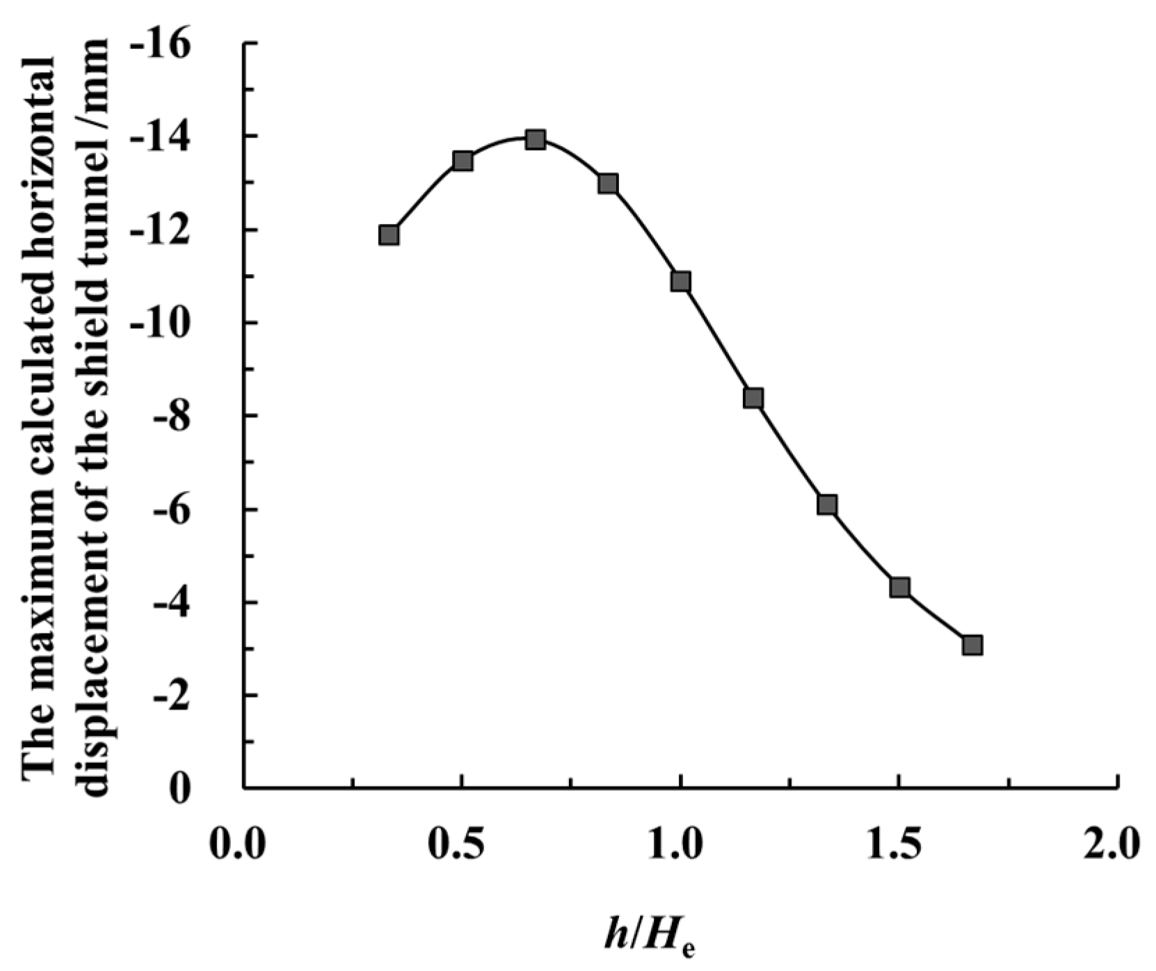
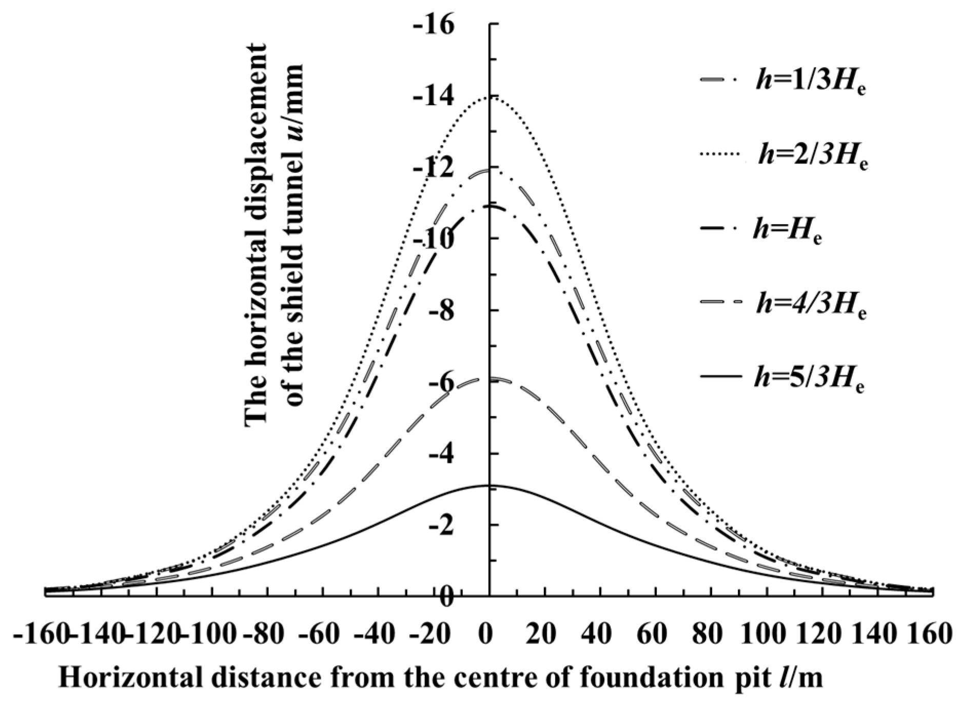
Taking Case History 1 in this paper as the basic working condition, under the condition that the other parameters remained constant, only the buried depth h of the tunnel by the side of the foundation pit was changed. Figure 20 shows the maximum calculation value of the horizontal displacement of the shield tunnel by the side of the foundation pit, changing with the ratio of the buried depth of the tunnel axis to the excavated depth. Figure 21 shows the longitudinal distribution curve of the calculated horizontal displacement value of the shield tunnel by the side of the foundation pit when the buried depth h equaled 1/3 He, 2/3 He, He, 4/3 He, and 5/3 He, respectively. As shown in Figure 20 and Figure 21, the excavation of the foundation pit had a great impact on the adjacent shield tunnel with a shallow burial depth. In this calculation, the horizontal displacement of the adjacent tunnel was the largest when the depth of the tunnel axis was about two-thirds of the excavation depth. At this time, the excavation face was about 2 m below the bottom of the tunnel. Subsequently, with the increase of the adjacent shield tunnel’s buried depth, the horizontal displacement of the tunnel caused by the excavation of the foundation pit obviously decreased. Meanwhile, the influence range of the longitudinal deformation of the shield tunnel also decreased.

7. Conclusions

In this paper, a sidewall unloading model can consider the deformation of the retaining structure, and the spatial effect of the foundation pit has been established. The longitudinal deformation of the shield tunnel by the side of the foundation pit has been studied with the collaborative deformation model, which combined the rotation and dislocation of the shield tunnel. Meanwhile, the verification of calculated cases and the analysis of influence factors have been carried out. Thus, the following conclusions have been obtained:
(1)
The calculated results of the method in this paper are in good agreement with the measured values, and the horizontal displacement of the shield tunnel axis by the side of the foundation pit presents a normal distribution. The longitudinal deformation of the adjacent tunnel is mainly caused by the unloading effect of the foundation pit sidewall, which is parallel and close to the tunnel. When the excavation depth is in the soil layer near the buried depth of the adjacent tunnel, the longitudinal deformation of the shield tunnel by the side of the foundation pit will increase sharply. Thus, more attention should be paid to the control of the tunnel’s deformation in this working condition.
(2)
The horizontal displacement near the excavation center of the foundation pit is relatively large, but the values of the dislocation and rotation angle between the segment rings are relatively small. The maximum rotation angle between the segment rings, the maximum dislocation and the maximum shear force between the segment rings all appear in the vicinity of the two inflexion points of the horizontal displacement curve of the tunnel.
(3)
With the increase of the retaining structure’s deformation, the longitudinal deformation of the adjacent shield tunnel and its influence range also increase. The longitudinal deformation of the adjacent shield tunnel decreases with the increase of the clearance between the foundation pit and the tunnel. The foundation pit’s excavation has a great influence on the adjacent shield tunnel at a shallow burial depth. Moreover, the impacts on the tunnel caused by the excavation decrease with the increase of the burial depth of the adjacent tunnel.
In addition, the distribution of the soil layer, the shape of the foundation pit, and construction factors are simplified in this study, and there are some deviations from the actual engineering situation. Therefore, more factors should be considered for further study.

Author Contributions

Conceptualization, methodology, software, validation and original draft preparation, X.Z.; guidance, review and revision, G.W.; translation, editing and review, C.J. All authors have read and agreed to the published version of the manuscript.

Funding

This research was supported by National Natural Science Foundation of China (Grant No. 51,778,576).

Acknowledgments

We are grateful to other members of our research team (Wang, X.; Qi, Y.J.; Zhou, X.X.) for their support.

Conflicts of Interest

The authors declare no conflict of interest.

References

  1. Yan, J.Y.; Wang, R.L. Cause analysis and typical characteristics of settlement and transverse convergence deformation of metro tunnel in soft ground in Shanghai. J. Nat. Disasters 2018, 27, 178–187. (In Chinese) [Google Scholar]
  2. Wang, H. Influence of deep excavation on the adjacent existing shielded subway tunnels. Soil Eng. Found. 2019, 33, 19–22. [Google Scholar]
  3. Yang, Y.B.; Zhou, B.; Xie, X.Y. Study on transverse deformation and cracking property of shield-driven tunnel induced by adjacent excavation. Chin. J. Rock Mech. Eng. 2016, 35 (Suppl. 2), 4082–4093. (In Chinese) [Google Scholar]
  4. Zhou, Z.L.; Chen, S.G.; Tu, P.; Zhang, H.S. An analytic study on the deflection of subway tunnel due to adjacent excavation of foundation pit. J. Mod. Transport. 2015, 23, 287–297. [Google Scholar] [CrossRef] [Green Version]
  5. Zhang, Z.G.; Zhang, M.X.; Wang, W.D. Two-stage method for analyzing effects on adjacent metro tunnels due to foundation pit excavation. Rock Soil Mech. 2011, 32, 2085–2092. (In Chinese) [Google Scholar]
  6. Zheng, G.; Du, Y.M.; Cheng, X.S.; Diao, Y.; Deng, X.; Wang, F.J. Characteristics and prediction methods for tunnel deformations induced by excavations. Geomech. Eng. 2017, 12, 361–397. [Google Scholar] [CrossRef]
  7. Shi, J.W.; Ng, C.W.W.; Chen, Y.H. Three-dimensional numerical parametric study of the influence of basement excavation on existing tunnel. Comput. Geotech. 2015, 63, 146–158. [Google Scholar] [CrossRef]
  8. Ng, C.W.W.; Shi, J.W.; Mašín, D.; Sun, H.S.; Lei, G.H. Influence of sand density and retaining wall stiffness on the three-dimensional responses of a tunnel to basement excavation. Can. Geotech. J. 2015, 52, 1811–1829. [Google Scholar] [CrossRef]
  9. Wang, L.F.; Pang, J.; Xu, Y.F.; Yang, K.F. Influence of foundation pit excavation on adjacent metro tunnels. Rock Soil Mech. 2016, 37, 2004–2010. (In Chinese) [Google Scholar]
  10. Simpson, B.; Vardanega, P.J. Results of monitoring at the British Library excavation. Proc. ICE-Geotech. Eng. 2014, 167, 99–116. [Google Scholar] [CrossRef] [Green Version]
  11. Chen, R.; Meng, F.; Li, Z.; Ye, Y.; Ye, J. Investigation of response of metro tunnels due to adjacent large excavation and protective measures in soft soils. Tunn. Undergr. Space Technol. 2016, 58, 224–235. [Google Scholar] [CrossRef] [Green Version]
  12. Meng, F.Y.; Chen, R.P.; Kang, X. Effects of tunneling-induced soil disturbance on post-construction settlement in structured soft soils. Tunn. Undergr. Space Technol. 2018, 80, 53–63. [Google Scholar] [CrossRef]
  13. Devriendt, M.; Doughty, L.; Morrison, P.; Pillai, A. Displacement of tunnels from a basement excavation in London. Geotech Eng. 2010, 163, 131–145. [Google Scholar] [CrossRef]
  14. Kitiyodom, P.; Matsumoto, T.; Kawaguchi, K. A simplified analysis method for piled raft foundations subjected to ground movements induced by tunneling. Int. J. Numer. Anal. Meth. Geomech. 2005, 29, 1485–1507. [Google Scholar] [CrossRef]
  15. Huang, M.S.; Zhang, C.R.; Li, Z. A simplified analysis method for the influence of tunneling on grouped piles. Tunn. Undergr. Space Technol. 2009, 24, 410–422. [Google Scholar] [CrossRef]
  16. Zhang, Z.G.; Zhang, M.X.; Zhao, Q.H. A simplified analysis for deformation behavior of buried pipelines considering disturbance effects of underground excavation in soft clays. Arab. J. Geosci. 2015, 8, 7771–7785. [Google Scholar] [CrossRef]
  17. Liang, R.Z.; Xia, T.D.; Huang, M.S.; Lin, C.G. Simplified method for evaluating the effects of adjacent excavation on shield tunnel considering the shearing effect. Comput. Geotech. 2017, 81, 167–187. [Google Scholar] [CrossRef]
  18. Liang, R.Z.; Wu, W.B.; Yu, F.; Jiang, G.S.; Liu, J.W. Simplified method for evaluating shield tunnel deformation due to adjacent excavation. Tunn. Undergr. Space Technol. 2018, 71, 94–105. [Google Scholar] [CrossRef]
  19. Zhang, Z.G.; Huang, M.S.; Wang, W.D. Evaluation of deformation response for adjacent tunnels due to soil unloading in excavation engineering. Tunn. Undergr. Space Technol. 2013, 38, 244–253. [Google Scholar] [CrossRef]
  20. Zhang, J.F.; Chen, J.J.; Wang, J.H.; Zhu, Y.F. Prediction of tunnel displacement induced by adjacent excavation in soft soil. Tunn. Undergr. Space Technol. 2013, 36, 24–33. [Google Scholar] [CrossRef]
  21. Wang, T.; Li, H.; Xu, R.Q. Analysis of deformation of shield tunnel when vertical loading and unloading. Mod. Transp. Technol. 2008, 15, 29–31, 57. (In Chinese) [Google Scholar]
  22. Zhou, S.H.; He, C.; Xiao, J.H. Energy method for calculating deformation of adjacent shield tunnels due to foundation pit excavation considering step between rings. China Railw. Sci. 2016, 37, 53–60. (In Chinese) [Google Scholar]
  23. Wei, G.; Hong, W.Q.; Wei, X.J.; Zhang, X.H.; Luo, J.W. Calculation of rigid body rotation and shearing dislocation deformation of adjacent shield tunnels due to excavation of foundation pits. Chin. J. Geotech. Eng. 2019, 41, 1251–1259. (In Chinese) [Google Scholar]
  24. Jiang, Z.H.; Zhang, Y.X. Calculation of influence on longitudinal deformation of adjacent tunnels due to excavation. J. Civil Archit. Environ. Eng. 2013, 35, 7–11. (In Chinese) [Google Scholar]
  25. Wei, G.; Zhao, C.L. Calculation method of additional load of adjacent metro tunnels due to foundation pit excavation. Chin. J. Rock Mech. Eng. 2016, 35 (Suppl. 1), 3408–3417. (In Chinese) [Google Scholar]
  26. Ding, Z.; Wang, D.; Wang, J.Y.; Wei, X.J. Deformation characteristics of Zhejiang soft soil deep foundation pits and their predictive analysis. Rock Soil Mech. 2015, 36 (Suppl. 1), 506–512. (In Chinese) [Google Scholar]
  27. Liu, M.L.; Fang, Q.; Zhang, D.L.; Hou, Y.J. Prediction of transient deformation due to excavation based on improved MSD method. Chin. J. Rock Mech. Eng. 2018, 37, 1700–1707. (In Chinese) [Google Scholar]
  28. Ou, C.Y.; Chiou, D.C.; Wu, T.S. Three-Dimensional finite element analysis of deep excavations. J. Geotech. Eng. 1996, 122, 337–345. [Google Scholar] [CrossRef]
  29. Liu, N.W.; Gong, X.N.; Yu, F.; Fang, K. Analysis of spatial effects in strutted excavation and related influential factors. Rock Soil Mech. 2014, 35, 2293–2298. (In Chinese) [Google Scholar]
  30. Finno, R.J.; Blackburn, J.T.; Roboski, J.F. Three-Dimensional effects for supported excavations in clay. J. Geotech. Geoenviron. Eng. 2007, 133, 30–36. [Google Scholar] [CrossRef] [Green Version]
  31. Xu, R.Q. Methods of earth pressure calculation for excavation. J. Zhejiang Univ. (Eng. Sci.) 2000, 34, 370–375. (In Chinese) [Google Scholar]
  32. Ko, C.T.; Chen, Y.B.; Gao, H.B.; Cao, X. Calculation model and application of non-limit earth pressure considering displacement of retaining structure. Water Resour. Power. 2013, 31, 127–131. (In Chinese) [Google Scholar]
  33. Mindlin, R.D. Force at a point in the interior of a semi-infinite solid. Physics 1936, 7, 195–201. [Google Scholar] [CrossRef]
  34. Wei, G.; Zhang, X.H. Calculation of rotation and shearing dislocation deformation of underlying shield tunnels due to foundation pit excavation. J. Cent. South. Univ. (Sci. Technol.) 2019, 50, 2273–2284. (In Chinese) [Google Scholar]
  35. Guo, L.; Yang, X.A.; Qiu, Y. Longitudinal heterogeneous equivalent continuous model for stagger joint segmental lining. Urban. Mass Transit. 2017, 20, 17–22. (In Chinese) [Google Scholar]
  36. Vesic, B.A. Bending of beams resting on isotropic elastic solids. J. Eng. Mech. 1961, 87, 35–53. [Google Scholar]
  37. Ye, F.; He, C.; Zhu, H.H.; Sun, H.D. Longitudinal equivalent rigidity analysis of shield tunnel considering transverse characteristics. Chin. J. Geotech. Eng. 2011, 33, 1870–1876. (In Chinese) [Google Scholar]
  38. Wei, G.; Li, J.; Xuan, H.L.; Dong, L.Z.; Xu, Y.Y.; Zhang, S.M. Monitoring data analysis on the influence of large deep foundation pit excavation on nearby metro shield tunnel. J. Railw. Sci. Eng. 2018, 15, 718–726. (In Chinese) [Google Scholar]
  39. Shao, H.; Wang, R. Monitoring Data Analysis on Influence of Operating Metro Tunnel by Nearly Excavation Construction. Chin. J. Undergr. Space Eng. 2011, 7 (Suppl. 1), 1403–1408. (In Chinese) [Google Scholar]
  40. Liao, S.M.; Wei, S.F.; Tan, Y.; Liu, J.X. Field performance of large-scale deep excavations in Suzhou. Chin. J. Geotech. Eng. 2015, 37, 458–469. (In Chinese) [Google Scholar]
  41. Wang, Z.Y. Research on Deformation Behavior of Deep Excavation with Bracing Diaphragm Wail in Hangzhou Area; Zhejiang University: Hangzhou, China, 2017. (In Chinese) [Google Scholar]
  42. Xu, Z.H.; Wang, J.H.; Wang, W.D. Deformation behavior of diaphragm walls in deep excavations in Shanghai. China Civ. Eng. J. 2008, 41, 81–86. (In Chinese) [Google Scholar]
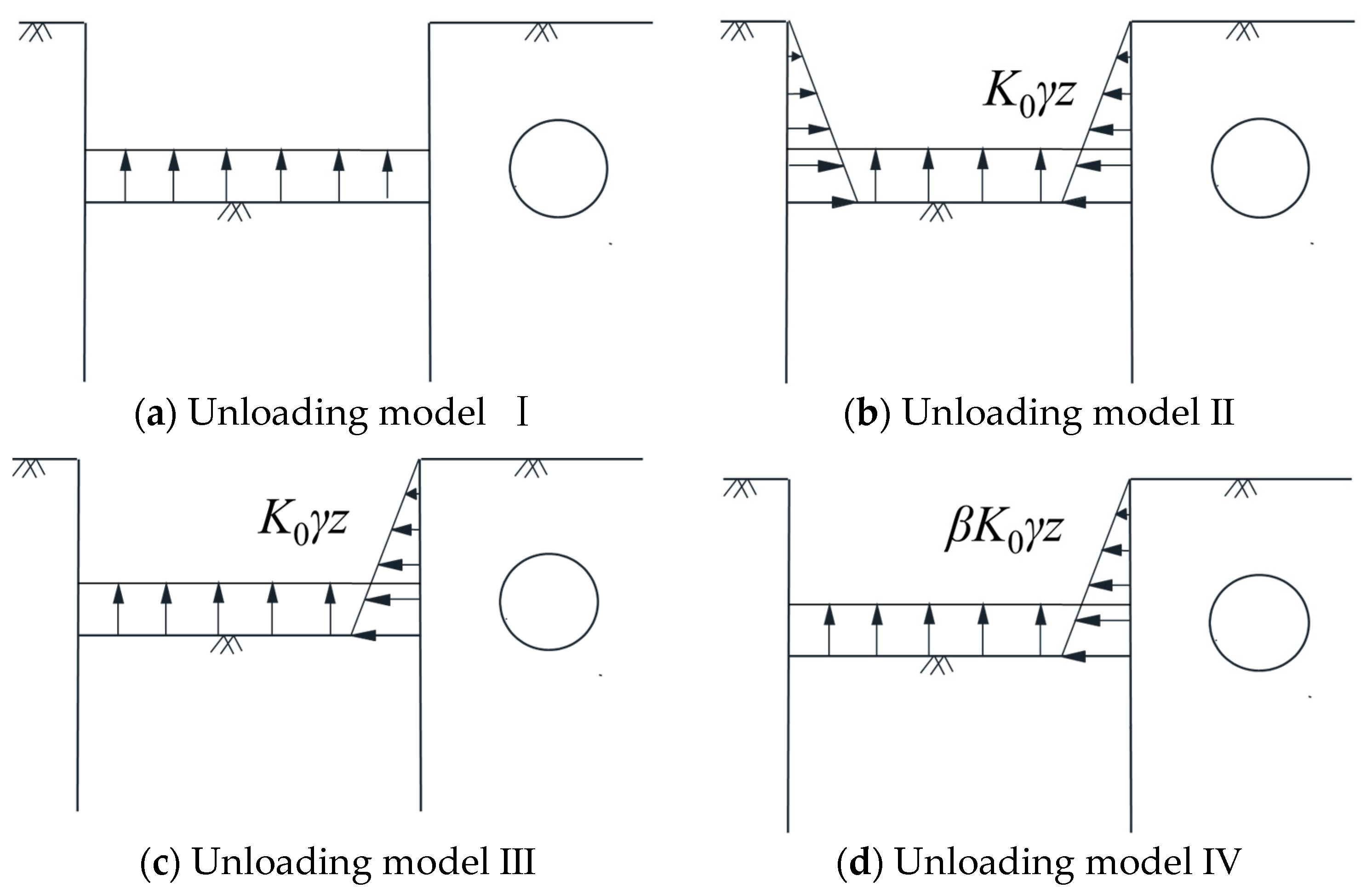
Figure 1. Schematic diagram of the foundation pit unloading model (K0 is the coefficient of static earth pressure, γ is the unit weight of soil for calculation, z is the depth of the calculation point and β is the stress loss rate).
Symmetry 12 02103 g001
Figure 2. Deformation diagram of the sidewall retaining structure.
Symmetry 12 02103 g002
Figure 3. Schematic diagram for the spatial effect of the foundation pit.
Symmetry 12 02103 g003
Figure 4. The schematic diagram of the position relationship and influence between the foundation pit and the adjacent shield tunnel.
Symmetry 12 02103 g004
Figure 5. The schematic diagram about the partition of the region affected by the unloading of the sidewall.
Symmetry 12 02103 g005
Figure 6. Schematic diagram for collaborative deformation mode of the shield tunnel.
Symmetry 12 02103 g006
Figure 7. Calculation model for the collaborative deformation of rotation and dislocation between the shield tunnel segment rings.
Symmetry 12 02103 g007
Figure 8. Comparison of the calculated values and measured values of the horizontal displacement of the shield tunnel adjacent to the foundation pit.
Symmetry 12 02103 g008
Figure 9. Horizontal displacement curve of the tunnel, caused by the unloading of each sidewall of the foundation pit.
Symmetry 12 02103 g009
Figure 10. Horizontal displacement curve of the tunnel during the process of excavation, layer by layer.
Symmetry 12 02103 g010
Figure 11. Longitudinal distribution of dislocation and rotation between the segment rings of the shield tunnel.
Symmetry 12 02103 g011
Figure 12. Longitudinal distribution of shear forces between the segment rings in the shield tunnel.
Symmetry 12 02103 g012
Figure 13. Comparison of the calculated value and measured value of the horizontal displacement of the tunnel beside the foundation pit.
Symmetry 12 02103 g013
Figure 14. The value of dislocation and rotation angle between the shield tunnel segments.
Symmetry 12 02103 g014
Figure 15. Longitudinal distribution of shear forces between the shield tunnel segments.
Symmetry 12 02103 g015
Figure 16. The variation curve of the maximum calculated value of the shield tunnel’s horizontal displacement with different values of vmax/He.
Symmetry 12 02103 g016
Figure 17. The longitudinal distribution curve of the adjacent tunnel’s horizontal displacement when vmax/He takes different values.
Symmetry 12 02103 g017
Figure 18. The calculated curve of the maximum horizontal displacement of the shield tunnel by the side of the foundation pit changing with s/He.
Symmetry 12 02103 g018
Figure 19. The longitudinal distribution curve of the horizontal displacement of the shield tunnel by the side of the foundation pit under different s/He conditions.
Symmetry 12 02103 g019
Figure 20. The changing curve of the maximum horizontal displacement (calculated) of the adjacent shield tunnel with different h/He values.
Symmetry 12 02103 g020
Figure 21. The longitudinal distribution curve of the horizontal displacement of the shield tunnel by the side of the foundation pit under different h/He conditions.
Symmetry 12 02103 g021
Publisher’s Note: MDPI stays neutral with regard to jurisdictional claims in published maps and institutional affiliations.