Article

A Novel Comprehensive Kinematic and Inverse Dynamic Model for the Flybar-Less Swashplate Mechanism: Application on a Small-Scale Unmanned Helicopter

1
School of Mechanical and Aerospace Engineering, Jilin University, Changchun 130022, China
2
College of Automotive Engineering, Jilin Engineering Normal University, Changchun 130022, China
*
Author to whom correspondence should be addressed.
Symmetry 2020, 12(11), 1849; https://doi.org/10.3390/sym12111849
Submission received: 12 October 2020 / Revised: 5 November 2020 / Accepted: 6 November 2020 / Published: 9 November 2020
(This article belongs to the Section Computer)

Abstract

:
In this paper, we propose a novel kinematic and inverse dynamic model for the flybar-less (FBL) swashplate mechanism of a small-scale unmanned helicopter. The swashplate mechanism is an essential configuration of helicopter flight control systems. It is a complex, multi-loop chain mechanism that controls the main rotor. In recent years, the demand for compact swashplate designs has increased owing to the development of small-scale helicopters. The swashplate mechanism proposed in this paper is the latest architectures used for hingeless rotors without a Bell-Hiller mixer. Firstly, the kinematic analysis is derived from the parallel manipulators concepts. Then, based on the principle of virtual work, a methodology for deriving a closed-form dynamic equation of the FBL swashplate mechanism is developed. Finally, the correctness and efficiency of the presented analytical model are demonstrated by numerical examples and the influence factors of the loads acted on actuators are discussed.

1. Introduction

The swashplate mechanism is a complex parallel manipulator steering control mechanism used in almost all helicopters [1,2]. The swashplate mechanism is a complex nonlinear system, and the most important component of the control system. It typically has three degrees of freedom (DOF) that produce pitch, heave, and roll motions. These three controls determine the pitch angles of the main rotor blades, and control the flight attitude of the helicopter [3].
Lange et al. performed a comprehensive kinematic model of the swashplate used in a CL-327 Guardian unmanned helicopter [4]. The kinematic formulation is derived within the framework of the forward and inverse kinematics of parallel robotic manipulators. Furthermore, the method of the natural orthogonal complement (NOC) [5] is employed to complete the dynamic analysis of this mechanism with the derivation of the equations of motion free of constraint wrenches [6]. Sabaapour and Zohoor completed another systematic research about the swashplate mechanism with a Bell-Hiller mixer, which is widely used in small-scale helicopters [7]. The dynamic analysis in [8] is based on the principle of virtual work and the concept of link Jacobian matrices [9]. Moreover, a fast inverse kinematic solution for a four-point swashplate mechanism was completed by Khaligh et al. [10]. Additionally, a simplified kinematic analysis based on using homogenous transformation and spatial configuration of the connecting linkages was presented by Saffarian and Fahimi [11]. Although modeling such a mechanism has been discussed well in the above papers, the dynamics of a swashplate mechanism is still lacking in the literature. Additionally, there is a lack of investigation of a simplified model without the stabilizer flybar.
The swashplate mechanism is usually equipped with a Bell-Hiller mixer [12] to improve the cyclic stability and make the cyclic control much more manageable. The effect of the flybar flapping angle is considered to be a key configuration of the blades pitch angle, which contributes greatly to the complexity of the dynamic modeling process. Additionally, a kinematic analysis of the Bell-Hiller mixer is difficult. The dialytic elimination method was used in [7], and resulted in a 48th-order polynomial which was too complex for real-time calculating. Although the Sylvester-Type Elimination method presented in [10] is more efficient, the method requires a certain amount of computations. Moreover, the flybar-less (FBL) swashplate mechanism is less complex in structure and lighter in weight. Another advantage of such an FBL rotor is that the inputs from the swashpate go directly to the main rotor blades for a fast and direct response [13]. Therefore, for many of the latest small-scale helicopters with higher maneuverability, the stabilizer flybar has been replaced by the electronic stabilization systems [14,15].
It should be noted that although the proposed FBL swashplate mechanism without the Bell-Hiller mixer is simpler than the traditional configuration, the whole mechanism is still a multi-loop mechanism chain with multiple DOF and complex topological configuration. In the kinematic analysis, it is crucial to derive a compact and precise inverse kinematic method to calculate the actuator inputs for real-time control applications. At the same time, the velocity analysis and acceleration analysis are essential for the dynamic analysis. Additionally, the kinematic model is important for the optimization of the swashplate mechanism [10].
The dynamic analysis of swashplate mechanism is complicated by the existence of two layers of parallel configuration with multiple closed-loop chains [16]. There are three well-known approaches to solve the dynamic problems for the real-time control of such a parallel manipulator [17]: the Newton-Euler formulation [18,19], the Lagrangian formulation [20,21], and the principle of virtual work [22,23]. The Newton-Euler method requires the motion equations to be written for each component, which leads to a large number of equations; it is a difficult task to eliminate the joint reactions economically. Thus, this method is not useful for the control system development. The Lagrangian formulation requires the derivatives of the kinetic energy of the whole mechanism, which is very complex in terms of a set of independent generalized coordinates. Other approaches have also been suggested [24,25,26,27]. The principle of virtual work is the most efficient method [28] for the dynamic analysis of parallel manipulators which allows the elimination of the constraint forces and moments at motion equations.
In this paper, the particular FBL swashplate mechanism is split into two submodules. A complete and precise kinematic model is derived by breaking each loop at a certain point and express the position of a selected point from two open chains that form the loop together with respect to a fixed framework. The nonlinear inverse kinematic relationship between the main rotor and swashplate mechanism is solved with specific spatial positioning of the rotating blades. We also derive the Jacobian matrices of each component. The principle of virtual work is employed to solve the inverse dynamics of the swashplate mechanism. The corresponding dynamic formulation is presented in closed form. The dynamic model provides a useful tool for the actuators’ load analysis.
The remainder of this paper is organized as follows: in Section 2, the mechanical model of the FBL swashplate mechanism is described. The kinematic analysis is done, including the position, velocity, and acceleration analysis. The complete inverse dynamic model of the FBL swashplate mechanism is derived. In Section 3, we prove the correctness of the whole model by comparing the calculated results with the simulation results, after which the load analysis of the actuators is performed. In Section 4, we conclude the work.

2. Methods

2.1. Mechanical Model

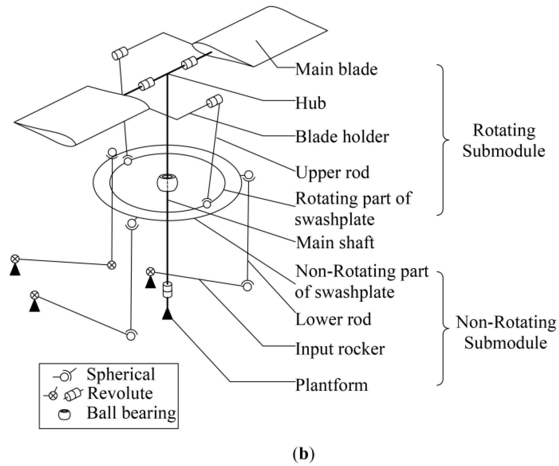
The FBL swashplate mechanism of a small-scale helicopter is shown in Figure 1a. A simplified mechanical model without drag arm is shown in Figure 1b. The whole mechanism is split into two parts: the Non-Rotating submodule (NR-SM) and the Rotating submodule (R-SM). The NR-SM is actually a 3-DOF motion platform. Thus, the attitude of the swashplate can be determined by three parameters: pitch, roll, and heave. The three actuators are fixed on the platform of the helicopter body and connected to the Non-Rotating part of the swashplate in a 120° arrangement through lower rods and input rockers. The swashplate is located on the main rotor shaft through the swashplate ball bearing, which is a combination of spherical and cylindrical joints. The cylindrical components allow a sliding motion (collective control, heave) along the axis of the main shaft as well as a rotation around the shaft. The spherical components enable the swashplate to rotate about two axes in its plane (cyclic controls, pitch and roll).
The rotating part of the swashplate is located on the non-rotating part through a revolute. The two main blades are connected to the rotating part with blade holders and upper rods. Each main blade is mounted to the hub by means of a revolute joint. The whole R-SM is allowed to rotate with the main rotor shaft. The R-SM is greatly simplified without the Bell-Hiller mixer. The main blades have a more direct response to the actuators’ inputs.

2.2. Kinematic Analysis

Each submodule is analyzed separately with the concept of parallel manipulators. These two submodules can be related by the kinematic relationship between the two parts of the swashplate.

2.2.1. Inverse Kinematic Analysis

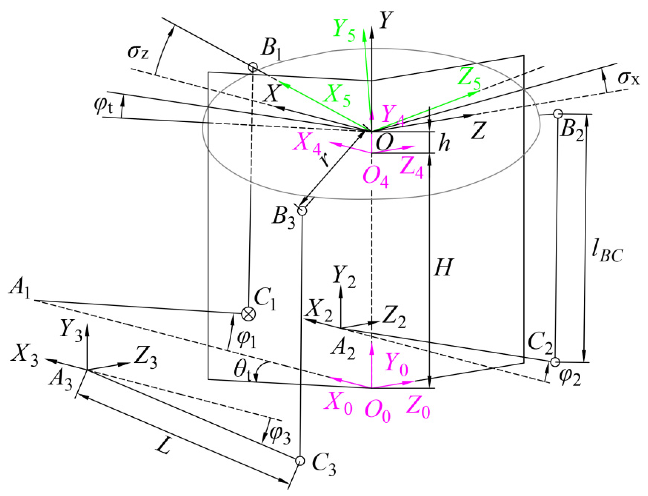
For the NR-SM, the output attitude of the swashplate can be obtained through the actuators. Orientations σ X and σ Z , and the displacement h of the swashplate, correspond to input actuator angles φ 1 , φ 2 , and φ 3 , respectively (Figure 2), calculated using the inverse kinematic equations.
The kinematic relationship of the swashplate mechanism is illustrated in Figure 2. The original coordinate system is given by O 0 X 0 Y 0 Z 0 . A global frame O X Y Z is introduced at the center of the swashplate, while its Y axis coincides with the rotating axis of the shaft and the O X Y parallels to platform’s base plate. The direction O 0 Y 0 coincides with the swashplate axis and the direction of O 0 X 0 points to A 1 . A local coordinate frame, A i X i Y i Z i , is attached to each limb such that its origin is located at point A i . B i and C i represent the center of the corresponding joint. The origin of the moving coordinate system O X 5 Y 5 Z 5 is O , which is the center of the swashplate plane. The positive direction of O Y 5 is the direction of the normal vector with respect to the upper surface of the swashplate, and the direction of O X 5 points to B 1 . O X 5 Y 5 Z 5 and O X 4 Y 4 Z 4 are the same in the initial state. The angle between O 0 X 0 and O X 5 is σ Z . The angle between the intersecting line (plane O 0 Y 0 Z 0 and the swashplate) and O 0 Z 0 is σ X . The radius of the swashplate is r . H is the distance between the center of the initial position of swashplate and the platform.
The attitude of the swashplate is characterized by three variables: σ X , σ Z , and h . The Euler angles α and β are used instead of σ X and σ Z for expressing the transformation from the initial position to a certain attitude. First, the linear displacement of the swashplate along O 0 Y 0 is denoted by h ( T Y h is obtained). Second, a rotation of α degrees along the Z axis gives R Z ( α ) . Lastly, the swashplate rotates β degrees along the X axis and R X ( β ) is obtained. The augmented rotation and transformation matrices are given by:
R X ( β ) = [ 1 0 0 0 0 cos β sin β 0 0 sin β cos β 0 0 0 0 1 ] , R Z ( α ) = [ cos α sin α 0 0 sin α cos α 0 0 0 0 1 0 0 0 0 1 ] , T Y h = [ 1 0 0 0 0 1 0 0 0 0 1 0 0 h 0 1 ]
The coordinates of A i in O 0 X 0 Y 0 Z 0 can be expressed in matrix form as:
A 0 = [ A 1 0 A 2 0 A 3 0 ] = [ L + r 0 0 1 L r sin 30 ° 0 r cos 30 ° 1 L r sin 30 ° 0 r cos 30 ° 1 ]
At any moment, the coordinates of B i in O X 5 Y 5 Z 5 can be expressed in matrix form as:
B 5 = [ B 1 5 B 2 5 B 3 5 ] = [ r 0 0 1 r sin 30 ° 0 r cos 30 ° 1 r sin 30 ° 0 r cos 30 ° 1 ]
With O 0 X 0 Y 0 Z 0 :
B 0 = B 5 C 5 0
where C 4 0 = T Y H , C 5 4 = R X ( β ) R Z ( α ) T Y h , C 5 0 = C 5 4 C 4 0 = R X ( β ) R Z ( α ) T Y h + H ; C i j represents the coordinate transformation from O i X i Y i Z i to O j X j Y j Z j . Thus:
B 0 = B 5 C 5 0 = [ b 1 , x 0 b 1 , y 0 b 1 , z 0 1 b 2 , x 0 b 2 , y 0 b 2 , z 0 1 b 3 , x 0 b 3 , y 0 b 3 , z 0 1 ]
Additionally:
A 0 = [ A 1 0 A 2 0 A 3 0 ] = [ a 1 , x 0 a 1 , y 0 a 1 , z 0 1 a 2 , x 0 a 2 , y 0 a 2 , z 0 1 a 3 , x 0 a 3 , y 0 a 3 , z 0 1 ]
where φ 1 can be solved in the A 1 C 1 B 1 O loop:
φ 1 = η γ
where:
γ = arcos L 2 + l A 1 B 1 2 l B 1 C 1 2 2 L l A 1 B 1 , l A 1 B 1 = ( b 1 , x 0 a 1 , x 0 ) 2 + ( b 1 , y 0 a 1 , y 0 ) 2 + ( b 1 , z 0 a 1 , z 0 ) 2 , η = arcsin b 1 , y 0 l A 1 B 1
The spatial relationships among coordinates are as shown in Figure 2. The transfer matrix is given by:
C 0 2 = T Z r cos 30 ° T X L + r sin 30 ° , C 0 3 = T Z r cos 30 ° T X L + r sin 30 °
Hence:
{ B 2 2 = B 2 0 C 0 2 = [ b 2 , x 0 L + r sin 30 ° b 2 , y 0 b 2 , z 0 r cos 30 ° 1 ] = [ b 2 , x 2 b 2 , y 2 b 2 , z 2 1 ] B 3 3 = B 3 0 C 0 3 = [ b 3 , x 0 + r sin 30 ° L b 3 , y 0 b 3 , z 0 + r cos 30 ° 1 ] = [ b 3 , x 3 b 3 , y 3 b 3 , z 3 1 ]
The linear distance between C i and B i is l B i C i , which can be converted into spatial coordinates as follows:
( b i , x i + L cos φ i ) 2 + ( b i , y i L sin φ i ) 2 + ( b i , z i ) 2 = l B i C i
Expanding and rearranging Equation (10) results in:
l B i C i 2 L 2 ( b i , x i ) 2 ( b i , y i ) 2 ( b i , z i ) 2 2 L ( b i , x i ) 2 + ( b i , y i ) 2 = b i , x i ( b i , x i ) 2 + ( b i , y i ) 2 cos φ i b i , y 2 ( b i , x 2 ) 2 + ( b i , y 2 ) 2 sin φ i
The inverse kinematic solution of φ i , for i = 2, 3, is given by:
φ i = θ i τ i
where:
τ i = arcsin l B i C i 2 L 2 ( b i , x i ) 2 ( b i , y i ) 2 ( b i , z i ) 2 2 L ( b i , x i ) 2 + ( b i , y i ) 2 ,   θ i = arcsin b i , x i ( b i , x i ) 2 + ( b i , y i ) 2
Note that the IK solutions of φ 1 , φ 2 , and φ 3 calculated in Equations (7) and (12) contain the Euler angles α and β , which are equal to the tilt angles of the swashplate σ X and σ Z in special cases.
As shown in Figure 2 and Figure 3, we now have the O X 0 Y 0 Z 0 coordinate. There is an intersecting line between the rotor and tilt planes. The angle between the intersecting line and O X 0 is φ t . The normal unit vectors of the rotor and tilt planes are defined as:
{ n 1 = [ sin θ t 0 cos θ t ] n 2 = [ 0 1 0 ]   [ cos α sin α 0 cos β   sin α cos β   cos α sin β sin β   sin α sin β   cos α cos β ] = [ cos β   sin α cos β   cos α sin β ]
The direction vector of the intersecting line is given by S i n t :
S i n t = n 1 × n 2 = | i j k cos β   sin   α cos β   cos α sin β sin θ t 0 cos θ t | = ( cos θ t   cos β   cos α ) i ( cos θ t   cos β   sin α sin θ t   sin β ) j + ( sin θ t   cos β   cos α ) k = [ cos θ t   cos β   cos α cos θ t   cos β   sin α + sin θ t   sin β sin θ t   cos β   cos α ] Τ
The direction vector of O X 0 is defined as S O X 0 :
S O X 0 = [ cos θ t 0 sin θ t ]
Therefore, φ t is given by:
tan ( φ t ) = | S O X 0 × S i n t | S O X 0 S i n t = cos θ t cos β   sin α + sin θ t   sin β cos β   cos α
Thus:
φ t ( θ t ) = arctan cos θ t   cos β   sin α + sin θ t   sin β cos β   cos α
Note that φ t is equal to σ Z when θ t = 0 ; thus, Equation (17) results in:
φ t ( 0 ° ) = σ Z = α
Substituting θ t = 270 into Equation (17), we have:
φ t ( 270 ° ) = σ X = arctan sin β cos β   sin α
Combining Equations (18) and (19) yields:
α = σ Z , β = arctan ( tan σ X   cos σ Z )
In this work, φ t was used to relate the R-SM and NR-SM. For the NR-SM, the corresponding σ Z equals φ t . Thus:
α = σ Z = arctan cos θ t   cos β   sin α + sin θ t   sin β cos β   cos α σ X = φ t ( θ t + 270 ° ) = arctan sin θ t   cos β   sin α cos θ t   sin β cos β   cos α
Therefore:
β = arctan ( tan σ X   cos σ Z ) = arctan ( cos α cos θ t   sin β sin θ t   cos β   sin α cos β   cos α )
The transformation matrix of the R-SM with respect to the local frame of the NR-SM is:
C 5 6 = R X ( β ) R Z ( α ) R Y ( θ t )
The purpose of the inverse kinematics of the NR-SM is determining the pose of the swashplate, i.e., σ Z , σ X , and h . However, for a precise θ t , only one set of pitch angles { θ b 1 , θ b 2 } θ t is known. Thus, at least two sets of pitch angles are necessary.
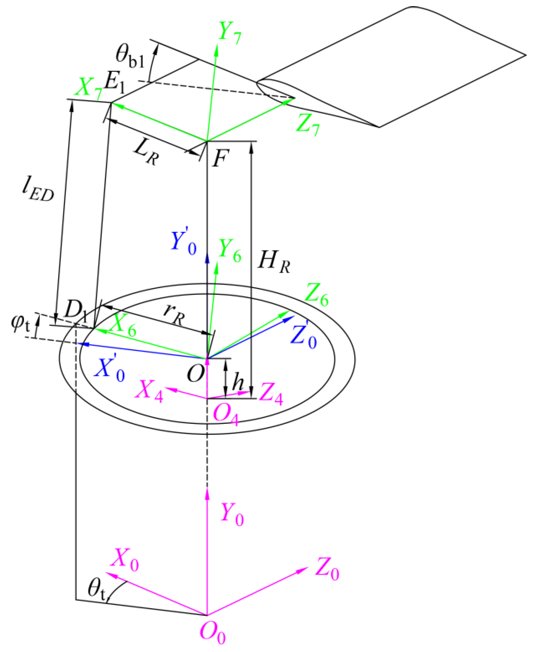
The kinematic relationship of NR-SM consists of two symmetrical parts. As shown in Figure 4, the blade1 side is presented; the blade2 side is simply mirrored in frame X 0 Y 0 Z 0 . Referring to Figure 4, the length of E D can be written as:
l E 1 D 1 2 = ( x D 1 0 x E 1 0 ) 2 + ( y D 1 0 y E 1 0 ) 2
where x D 1 0 = r R cos φ t , y D 1 0 = r R sin φ t + h , x E 1 0 = L R cos θ b 1 , y E 1 0 = L R sin θ b 1 + H R .
For θ t = 0 and θ t = 270 , the corresponding pitch angles are { θ b 11 , θ b 12 } θ t = 0 and { θ b 21 , θ b 22 } θ t = 270 (cyclic pitch inputs). Substituting these pitch angles into Equation (24) gives:
{ λ E 1 D 1 2 = ( cos σ Z + μ 11 ) 2 + ( sin σ Z + λ 11 ) 2 λ E 1 D 1 2 = ( cos σ Z + μ 12 ) 2 + ( sin σ Z + λ 12 ) 2 λ E 1 D 1 2 = ( cos σ X + μ 21 ) 2 + ( sin σ X + λ 21 ) 2 λ E 1 D 1 2 = ( cos σ X + μ 22 ) 2 + ( sin σ X + λ 22 ) 2
where:
λ i j = L R sin θ b i j + h H R r R , λ E 1 D 1 = l E 1 D 1 r R , μ i j = L R cos θ b i j r R
where σ Z , σ X , and h in Equation (25) can be solved through the same procedure used to solve Equation (30). However, dialytic elimination of such an equation is not suitable for real-time calculation. To make this process more efficient for real-time control, { θ b 01 } φ t = 0 (collective pitch input) is considered to be already known. Equation (24) yields:
l E 1 D 1 2 = ( r R L R cos θ b 01 ) 2 + ( L R sin θ b 01 + h H R ) 2
Therefore, h can be obtained with only one known parameter through Equation (26):
h = L R sin θ b 01 + H R ± l E 1 D 1 2 ( r R L R cos θ b 01 ) 2
Only the smaller solution is acceptable. Substituting the value of h into Equation (25), σ Z and σ X can be easily obtained:
σ Z = κ 11 ν 11 , σ X = κ 21 ν 21
where:
κ i j = arcsin λ E 1 D 1 2 λ i j 2 μ i j 2 1 2 μ i j 2 + λ i j 2 , ν i j = arcsin μ i j μ i j 2 + λ i j 2
Finally, the inverse kinematics of NR-SM is done in analytical solution with the three given inputs { θ b 01 } φ t = 0 , { θ b 11 } φ t = σ Z , and { θ b 21 } φ t = σ X .
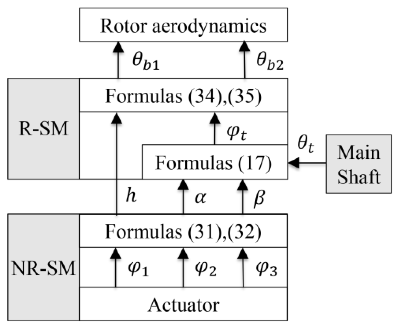
As illustrated in Figure 5, the inverse kinematics of the whole mechanism is derived in an analytical form, which is suitable for real-time control.

2.2.2. Direct Kinematic Analysis

Unlike common parallel mechanisms with matching individual loops, the A 1 C 1 B 1 O loop is designed to restrict the DOF. Here, direct position analysis was used to obtain the direct position and orientation of the swashplate, which makes the process more complicated.
According to the characterization presented in Figure 2 for each loop A i C i B i O , i = 1, 2, 3, the following vector equation was obtained:
{ B i C i = ( B i O ) + ( O A i ) + ( A i C i ) | B i C i | = H
By squaring Equation (29), the following three scalar equations are obtained for i = 1, 2, 3:
i q 1 S α S β + i q 2 C α S β + i q 3 h C α S β + i q 4 h S α + i q 5 C α + i q 6 S α + i q 7 C β + i q 8 h 2 + i q 9 h + i q 10 = 0
where i q j is constant and the values of these variates are defined as S α = sin α , C α = cos α , S β = sin β , and C β = cos β .
Using the well-known Weierstrass expression:
sin α = 2 x 2 1 + x 2 2 ,   cos α = 1 x 2 2 1 + x 2 2 ,   sin β = 2 x 3 1 + x 3 2 ,   cos β = 1 x 3 2 1 + x 3 2
where x 2 = tan α 2 , x 3 = tan β 2 .
Substituting x 1 for h , Equation (30) can be transformed into a system of three second-order algebraic equations in the unknown x 1 , x 2 , x 3 :
{ 2 A x 2 2 + 2 B x 2 + 2 C = 0 2 A x 3 2 + 2 B x 3 + 2 C = 0 3 A x 3 2 + 3 B x 3 + 3 C = 0
When i = 2, 3, Equation (30) contain all three unknowns, whereas it contains only two unknowns ( x 1 , x 2 ) when i = 1. First, x 3 can be eliminated from the second and third equation of Equation (31) according to the Sylvester theorem, which will result in an equation in the unknown x 1 , x 2 :
k = 0 8 G k x 2 k = 0
where each G k is a polynomial of a single indeterminate x 1 .
Then, x 2 can be eliminated in the same way by combining the Equation (32) and the first equation of the Equation (31). As a result, a polynomial equation in the unknown x 1 is gained:
i = 0 34 h i x 1 i = 0
where h i is constant when the actuators displacements ( φ i ) are given. Equation (33) has 34 simultaneous possible solutions for x 1 , which means that the swashplate mechanism has 34 theoretically possible positions for certain outputs. However, some of the solutions are impossible, and few are acceptable. Moreover, x 1 can be determined if the initial position of the swashplate mechanism was configured correctly.
If the solution of x 1 is applied to Equation (33), G k is converted into a numerical value. As a result, x 2 can be solved through Equation (32). Then, x 1 and x 2 can be applied to the second and third equation of Equation (31), so that x 3 is obtained. Finally, the position of the swashplate is uniquely defined.
The purpose of the direct kinematics of the R-SM is to determine the main blade pitch angles { θ b 1 , θ b 2 } θ t with the given σ Z , σ X , h , and θ t . Firstly, the corresponding φ t can be obtained through Equations (17) and (20). Then, solving Equation (24) for θ b 1 yields:
θ b 1 = κ + γ
where:
κ = arcsin l E D 2 r R 2 L R 2 H R 2 h 2 2 h r R sin φ t + 2 H R r R sin φ t + 2 h H R L R ( 2 H R 2 h 2 r R sin φ t ) 2 + ( 2 r R cos φ t ) 2 γ = arcsin 2 r R cos φ t ( 2 H R 2 h 2 r R sin φ t ) 2 + ( 2 r R cos φ t ) 2
For the blade2, the pitch angle θ b 2 can be easily obtained as:
θ b 2 ( θ t ) = θ b 1 ( θ t + 180 )
Figure 6 shows the global direct kinematics of the whole mechanism which is a part of the helicopter manipulation. The derived { θ b 1 , θ b 2 } θ t is needed in the rotor aerodynamics analysis.

2.2.3. Velocity Analysis

As shown in Figure 2, the vector loop of each chain can be written as:
O 0 B i = O 0 A i + A i C i + C i B i = O 0 O + O B i
where the constant magnitude vector connecting an initial point A i to a terminal C i is denoted by A i C i , and so on. Taking the derivative of Equation (36) with respect to time yields two equations. The velocity vector loop of each limb can be written as:
{ V B i = w A i × A i C i + w C i × C i B i V B i = V + Ω × O B i
where w A i = u A i φ ˙ i , V = [ 0 n y h ˙ 0 ] Τ , Ω = [ u w β ˙ 0 τ w α ˙ ] Τ .
u A i is the unit vector along the axis of the ith actuated joint. w A i is the input vector of each actuated joint. To eliminate w C i , dot multiplication was performed for both sides of Equation (37) with C i B i and the right-hand side was rewritten in matrix form:
[ u A i ( A i C i × C i B i ) ] [ φ ˙ 1 ] = [ n y C i B i u w ( C i B i × B i O ) τ w ( C i B i × B i O ) ] [ h ˙ β ˙ α ˙ ] Τ
The non-rotating submodule is a 3-DOF parallel manipulator, thus eliminating the zero elements in Equation (38), taking q ˙ = [ φ ˙ 1 φ ˙ 2 φ ˙ 3 ] Τ as the input vector of actuated joints. Using x ˙ = [ h ˙ β ˙ α ˙ ] Τ represents the linear and angular velocities of the moving swashplate. Therefore, we can write Equation (38) in a 3 × 3 matrix form:
[ u A 1 ( A 1 C 1 × C 1 B 1 ) 0 0 0 u A 2 ( A 2 C 2 × C 2 B 2 ) 0 0 0 u A 3 ( A 3 C 3 × C 3 B 3 ) ] [ φ ˙ 1 φ ˙ 2 φ ˙ 3 ] = [ n y C 1 B 1 u w ( C 1 B 1 × B 1 O ) τ w ( C 1 B 1 × B 1 O ) n y C 2 B 2 u w ( C 2 B 2 × B i O ) τ w ( C 2 B 2 × B 2 O ) n y C 3 B 3 u w ( C 3 B 3 × B 3 O ) τ w ( C 3 B 3 × B 3 O ) ] [ h ˙ β ˙ α ˙ ]
For A i C i × C i B i 0 , Equation (39) is a three scalar equation which can be written as:
q ˙ = J N R x ˙
where:
J N R = [ n y C 1 B 1 u A 1 ( A 1 C 1 × C 1 B 1 ) u w ( C 1 B 1 × B 1 O ) u A 1 ( A 1 C 1 × C 1 B 1 ) τ w ( C 1 B 1 × B 1 O ) u A 1 ( A 1 C 1 × C 1 B 1 ) n y C 2 B 2 u A 2 ( A 2 C 2 × C 2 B 2 ) u w ( C 2 B 2 × B 2 O ) u A 2 ( A 2 C 2 × C 2 B 2 ) τ w ( C 1 B 1 × B 1 O ) u A 2 ( A 2 C 2 × C 2 B 2 ) n y C 3 B 3 u A 3 ( A 3 C 3 × C 3 B 3 ) u w ( C 3 B 3 × B 3 O ) u A 3 ( A 3 C 3 × C 3 B 3 ) τ w ( C 1 B 1 × B 1 O ) u A 3 ( A 3 C 3 × C 3 B 3 ) ]
which is known as the manipulator Jacobian matrix.
As mentioned above, the R-SM rotates around the main shaft as a unity. First, we derive the velocity relations and the link Jacobian matrix for the R-SM with respect to the local frame X 0 Y 0 Z 0 . q ˙ = [ θ ˙ b 1 θ ˙ b 2 ] Τ was taken as the input vector of the main blades. Using x ˙ = [ h ˙ β ˙ α ˙ ] Τ represents the linear and angular velocities of the swashplate. Referring to Figure 4, the vector loop for each blade side can be written as:
O E i = O 4 F + F E i = O 4 O + O D i + D i E i
Taking the derivative of Equation (41) with respect to time yields:
V E i = θ ˙ b i u θ b i × F E i = V + Ω × O D i + w D i × D i E i
where u θ b i is the unit vector along the feathering axis of blade i.
To eliminate the w D i , dot multiplication was performed for each side of Equation (42) with D i E i and the right-hand side was rewritten in matrix form:
[ u θ b i ( F E i × D i E i ) ] [ θ ˙ b i ] = [ n y D i E i u w ( O D i × D i E i ) τ w ( O D i × D i E i ) ] [ 0 h ˙ 0 β ˙ 0 α ˙ ] Τ
Rewriting Equation (42) gives:
[ θ ˙ b 1 θ ˙ b 2 ] Τ = 0 J R [ 0 h ˙ 0 β ˙ 0 α ˙ ] Τ
where:
0 J R = [ 0 J 1 , h ˙ 0 J 1 , β ˙ 0 J 1 , α ˙ 0 J 2 , h ˙ 0 J 2 , h ˙ 0 J 2 , α ˙ ]
The velocities of the rotating part of swashplate can be expressed with respect to the initial frame X 4 Y 4 Z 4 :
V = R Y ( θ t ) Τ [ 0 0 h ˙ 0 ] Τ , Ω = R Y ( θ t ) Τ [ 0 β ˙ 0 0 α ˙ ] Τ + θ ˙ t n y
Hence, the Jacobian matrix of the R-SM can be obtained:
J R = [ 0 J 1 , h ˙ 0 J 1 , w R Y ( θ t ) 0 J 2 , h ˙ 0 J 2 , w R Y ( θ t ) 0 n y Τ ]
where R Y ( θ t ) is the rotation matrix of the local frame X 0 Y 0 Z 0 relative to the initial frame X 4 Y 4 Z 4 and J i , w = [ 0 J i , β ˙ 0 0 J i , α ˙ ] .

2.2.4. Acceleration Analysis

In this section, we derive the relationships between the angular acceleration of the actuated joint and the linear and angular accelerations of the moving swashplate. The rules of taking the derivative of a vector with respect to time defined as:
{ d d t A i C i = w A i × A i C i d d t ( A i C i × C i B i ) = ( w A i × A i C i ) × C i B i + A i C i × ( w C i × C i B i )
Taking the derivative of the right-hand sides of Equation (37) with respect to time yields:
{ a B = V ˙ B = w ˙ A i × A i C i + w A i × ( w A i × A i C i ) + w ˙ C i × C i B i + w C i × ( w C i × C i B i ) a B = V ˙ B = V ˙ + B i O × Ω ˙ + ( B i O × Ω ) × Ω
Dot multiplying both sides of Equation (48) with C i B i and rewriting it in matrix form gives:
[ φ ¨ 1 φ ¨ 2 φ ¨ 3 ] Τ = J [ h ¨ β ¨ α ¨ ] Τ + [ ξ 1 ξ 2 ξ 3 ] Τ
where:
ξ i = ( A i C i C i B i ) φ ˙ i 2 + ( C i B i C i B i ) ( w C i w C i ) + ( Ω C i B i ) ( Ω O B i ) ( O B i C i B i ) ( Ω Ω ) u A ( A i C i × C i B i )
To derive the angular velocity of the lower rod w C i , cross multiplication was performed for both sides of Equation (37) with C i B i . Since each rod does not spin about its own axis, we obtain:
w C i = 1 | C i B i | 2 [ C i B i × V + B i O ( C i B Ω ) Ω ( C i B B i O ) w A i ( C i B i A i C i ) + A i C i ( C i B i w A i ) ]
where | C i B i | expresses the module of vector C i B i .
The acceleration relationships of R-SM can be derived in the same way used above. First, taking the derivative of the right-hand sides of Equation (42) with respect to time yields:
θ ¨ b i u θ b i × F E i + θ ˙ b i u θ b i × ( θ ˙ b i u θ b i × F E i ) = V ˙ + Ω ˙ × O D i + Ω × ( Ω × O D i ) + w ˙ D i × D i E i + w D i × ( w D i × D i E i )
Dot multiplying both sides of Equation (51) with D i E i and rewriting it in matrix form gives:
[ θ ¨ b 1 θ ¨ b 2 ] Τ = 0 J R [ 0 h ¨ 0 β ¨ 0 α ¨ ] Τ + [ ξ 1 ξ 2 ] Τ
where:
ξ i = ( F E i D i E i ) θ ˙ b i 2 + ( Ω D i E i ) ( Ω O D i ) ( O D i D i E i ) ( Ω Ω ) + ( D i E i D i E i ) ( w D i w D i ) u θ b i ( D i E i × F E i )
To derive the angular velocity of the upper rod w D i , which is the only unknown parameter, cross multiplication was performed for both sides of Equation (42) with D i E i , which gives:
w D i = D i E i | D i E i | 2 × ( θ ˙ b i u θ b i × F E i V Ω × O D i )

2.3. Inverse Dynamic Analysis

According to d’Alembert’s principle, the resultant of the applied and inertia forces exerted at the center of mass of the ith body of a mechanism consists of N components is:
F i = [ f i n i ] = [ f e + m i g m i v ˙ i n e I i w ˙ i w i × ( I i w i ) ]
where f e and n e are the external force and moment applied at the center of mass of component i. v ˙ i and w ˙ i are the translational acceleration and angular acceleration. g and I i are the gravitational acceleration and inertial matrix.
Combining d’Alembert’s principle and the traditional principle of virtual work contributes to the critical step in the dynamic analysis:
δ q Τ τ + i = 1 n δ x i Τ F i = 0
where δ q and δ x i are the virtual displacements of the actuated joints and ith component, respectively. In this step, we relate the virtual displacements to the generalized virtual displacement of the moving platform by the Jacobian matrices. For each part:
δ q = J i δ x i
Substituting Equation (56) into Equation (55) yields:
δ q Τ ( τ + i = 1 n J i Τ F i ) = 0
Since Equation (57) is valid for any δ q , it follows that:
τ + i = 1 n J i Τ F i = 0
This step makes the dynamic modeling more efficient than the traditional ways, which is similar to Kane’s formulation.
For the A 1 C 1 rocker, the velocity vector of its center can be written as:
J A 1 C 1 1 q ˙ = x ˙ A 1 C 1
where:
x ˙ A 1 C 1 = [ c A 1 C 1 φ ˙ 1 sin φ 1 c A 1 C 1 φ ˙ 1 cos φ 1 φ ˙ 1 ] J A 1 C 1 1 = [ c A 1 C 1 sin φ 1 0 0 c A 1 C 1 cos φ 1 0 0 1 0 0 ]
and where q ˙ = [ φ ˙ 1 φ ˙ 2 φ ˙ 3 ] Τ is the input vector of actuated joints of NR-SM. It is not difficult to find that J A i C i 1 has the same form, as only the ith column is not zero. The resultant of applied and inertia forces exerted at the center of mass of the ith rocker is:
F A i C i = [ m A i C i g m A i C i v ˙ c , A i C i I z , A i C i φ ¨ i ]
where I z , A i C i is the z component of the moment of inertia of rocker A 1 C 1 around its mess center. Thus, the desired expression can be rewritten as:
i = 1 3 J A i C i Τ F A i C i = [ λ 1 λ 2 λ 3 ] Τ
where λ i = m A i C i c A i C i 2 φ ¨ i I z , A i C i φ ¨ i m A i C i g c A i C i cos φ i , and c A i C i is the distance between point A i and the center of mess of rocker A i C i .
For the non-rotating part of swashplate, the resultant of applied and inertia forces exerted at its center of mass can be expressed in the desired three-dimensional form by eliminating the zero elements:
F N R = [ f e , y m N R ( g + h ¨ ) n e , x + n N R , x n e , z + n N R , z ] Τ
where f e , y is the external force along Y axis exerted at the center of mass of the non-rotating swashplate, and n e , x and n N R , x ( n e , z and n N R , z ) are the external and inertia moments about X (Z) axis, respectively.
Hence, for the NR-SM Equation (58) can be written as:
τ N R = i = 1 3 J A i C i Τ F A i C i J N R Τ F N R = 0
where τ N R is the desired actuated torque. Note that the assistant lower rods are neglected in the dynamic modeling process of the NR-SM due to their light weights and low velocities. Only f e , y , n e , x , and n e , z are unknown in the right-hand side of Equation (63).
Note that the linear velocity of each blade does not exist and the external force does not contribute to the dynamic modeling. Therefore, for the blade1, the velocity vector of its center can be written as:
J b 1 1 q ˙ = x ˙ b 1
where:
w b 1 = [ θ ˙ b 1 sin θ t θ ˙ t θ ˙ b 1 cos θ t ] Τ , 7 w b 1 = [ θ ˙ t sin θ b 1 θ ˙ t cos θ b 1 θ ˙ b 1 ] Τ , v b 1 = w b 1 × c b 1 = [ θ ˙ t c cos θ t 0 c sin θ t ] Τ , J b 1 1 = [ 0 0 0 0 0 1 0 0 0 0 0 0 c cos θ t 0 c sin θ t sin θ b 1 cos θ b 1 0 ] Τ
and where q ˙ = [ θ ˙ b 1 θ ˙ b 2 θ ˙ t ] Τ is the input vector of actuated joints of R-SM. Equation (54) can be written as:
F b 1 = [ m b w ˙ b 1 × c b 1 I b 1 7 w ˙ b 1 7 w b 1 × ( I b 1 7 w b 1 ) ]
where I b 1 = d i a g ( [ I b , x , I b , y , I b , z ] ) is diagonal inertia matrix and I b , x , I b , y , and I b , z are the indicate the principle moments of inertia of main blades. 7 w b 1 is w b 1 expressed in the local frame X 7 Y 7 Z 7 , and so on. Thus, the desired equations can be derived by assembling the relations of two blades and eliminating some zero elements:
i = 1 2 J b i Τ F b i = [ J b 1 J b 2 J b 3 ] Τ
where:
J b j = i = 1 2 ( I b , x J b j , i , x + I b , y J b j , i , y + I b , z J b j , i , z ) + J b j , m
and where:
J b 1 , 1 , x = θ ˙ t 2 sin θ b 1 cos θ b 1   , J b 1 , 1 , y = J b 1 , 1 , x , J b 1 , 1 , z = θ ¨ b 1 , J b 1 , 2 , x = J b 1 , 2 , y = J b 1 , 2 , z = 0   , J b 2 , 1 , x = J b 2 , 1 , y = J b 2 , 1 , z = 0   , J b 2 , 2 , x = J b 1 , 1 , x , J b 2 , 2 , y = J b 1 , 1 , y , J b 2 , 2 , z = J b 1 , 1 , z , J b 3 , i , x = 2 θ ˙ t θ ˙ b i sin θ b i cos θ b i θ ¨ t sin 2 θ b i , J b 3 , i , y = 2 θ ˙ t θ ˙ b i sin θ b i cos θ b i θ ¨ t cos 2 θ b i , J b 3 , i , z = 0   , J b 1 , m = J b 2 , m = 0   , J b 3 , m = 2 m b c 2 θ ¨ t
For the blade holder1 of blade1, the angular and linear velocity transformed to the frame X 4 Y 4 Z 4 can be derived as:
w b h 1 = w b 1 = [ θ ˙ b 1 sin θ t θ ˙ t θ ˙ b 1 cos θ t ] Τ , 7 w b h 1 = 7 w b 1 = [ θ ˙ t sin θ b 1 θ ˙ t cos θ b 1 θ ˙ b 1 ] Τ , v b h 1 = w b 1 × c b h 1 = [ θ ˙ t ( c b , x cos θ b 1 sin θ t + c b , z cos θ t ) θ ˙ b 1 c b , x sin θ b 1 cos θ t θ ˙ b 1 c b , x cos θ b 1 θ ˙ t ( c b , x cos θ b 1 cos θ t c b , z sin θ t ) + θ ˙ b 1 c b , x sin θ b 1 sin θ t ]
where c b h 1 is the position vector of the center of mass of blade holder1. Therefore, the Jacobian matrix is given by:
J b h 1 1 = [ c b , x sin θ b 1 cos θ t 0 c b , x cos θ b 1 sin θ t + c b , z cos θ t θ ˙ b 1 c b , x cos θ b 1 0 0 c b , x sin θ b 1 sin θ t 0 c b , x cos θ b 1 cos θ t c b , z sin θ t 0 0 sin θ b 1 0 0 cos θ b 1 1 0 0 ]
F b h 1 can be obtained through Equation (54). Additionally, like Equation (66), assembling the relations of two blade holders and eliminating some zero elements gives:
i = 1 2 J b h i Τ F b h i = [ J b h 1 J b h 2 J b h 3 ] Τ
where:
J b h 1 = c b , x J b h , 2 , 1 + J b h , 6 , 1 ,   J b h 2 = c b , x J b h , 2 , 2 + J b h , 6 , 2 , J b h 3 = i = 1 2 ( c b , z cos θ b i J b h , 1 , i c b , z sin θ b i J b h , 2 , i c b , x cos θ b i J b h , 3 , i + sin θ b i J b h , 4 , i + cos θ b i J b h , 5 , i )
and where:
J b h , 1 , i = m b h c b , z θ ¨ t cos θ b i + m b h c b , z θ ˙ t θ ˙ b i sin θ b i m b h g sin θ b i , J b h , 2 , i = m b h c b , x θ ¨ b i + m b h c b , z θ ¨ t sin θ b i + m b h c b , z θ ˙ t θ ˙ b i cos θ b i m b h g cos θ b i , J b h , 3 , i = m b h c b , x θ ¨ t cos θ b i m b h c b , x θ ˙ t θ ˙ b i sin θ b i , J b h , 4 , i = I b h , x ( θ ¨ t sin θ b i + θ ˙ t θ ˙ b i cos θ b i ) ( I b h , z I b h , y ) θ ˙ t θ ˙ b i cos θ b i m b h g c b , x cos θ b i , J b h , 5 , i = I b h , y ( θ ¨ t cos θ b i θ ˙ t θ ˙ b i sin θ b i ) ( I b h , x I b h , z ) θ ˙ t θ ˙ b i sin θ b i , J b h , 6 , i = I b h , z θ ¨ t ( I b h , y I b h , x ) θ ˙ t 2 sin θ b i cos θ b i
For the rotating swashplate, the applied and inertia wrenches can be written as:
F R = [ f e , y m R ( g + h ¨ ) n e , x + n R , x n e , y + n R , y n e , z + n R , z ]
where f e , y is the external force along Y axis exerted at the center of mass of rotating swashplate, and n e , x and n N R , x ( n e , y and n N R , y ; n e , z and n N R , z ) are the external and inertia moments along the X (Y; Z) axis, respectively. Additionally, upper rods are neglected in the dynamic modeling process of the R-SM. To express the desired f e , y , n e , x , and n e , z , Equation (58) can be rewritten as:
F R = J R Τ ( τ R + i = 1 2 J b h i Τ F b h i + i = 1 2 J b i Τ F b i )
Given the actuated torques, τ R , f e , y , n e , x , and n e , z can be solved with Equation (71). Then, by substituting f e , y , n e , x , and n e , z into Equation (63), τ N R can be finally determined. Thus far, the inverse dynamic model of the whole mechanism has been established.

3. Results and Discussions

3.1. Numerical Validation

In this section, a numerical example is provided to exemplify the proposed methodology. First, the rigid body model of the whole swashplate mechanism is built and simulated using RecurDyn V9R1. Then, a computer program is developed using Matlab based on the mathematical model. Finally, the simulation results are compared with the analytical results.
The kinematic and dynamic parameters are given in Table 1. The rotation rate of the main shaft is 150 rpm.
The displacements of three actuators are expressed as:
{ φ 1 = 0 . 4 sin ( 13 t ) cos ( 12 t ) φ 2 = 0 . 5 sin ( 15 t ) cos ( 11 t ) φ 3 = 0 . 3 sin ( 7 t )
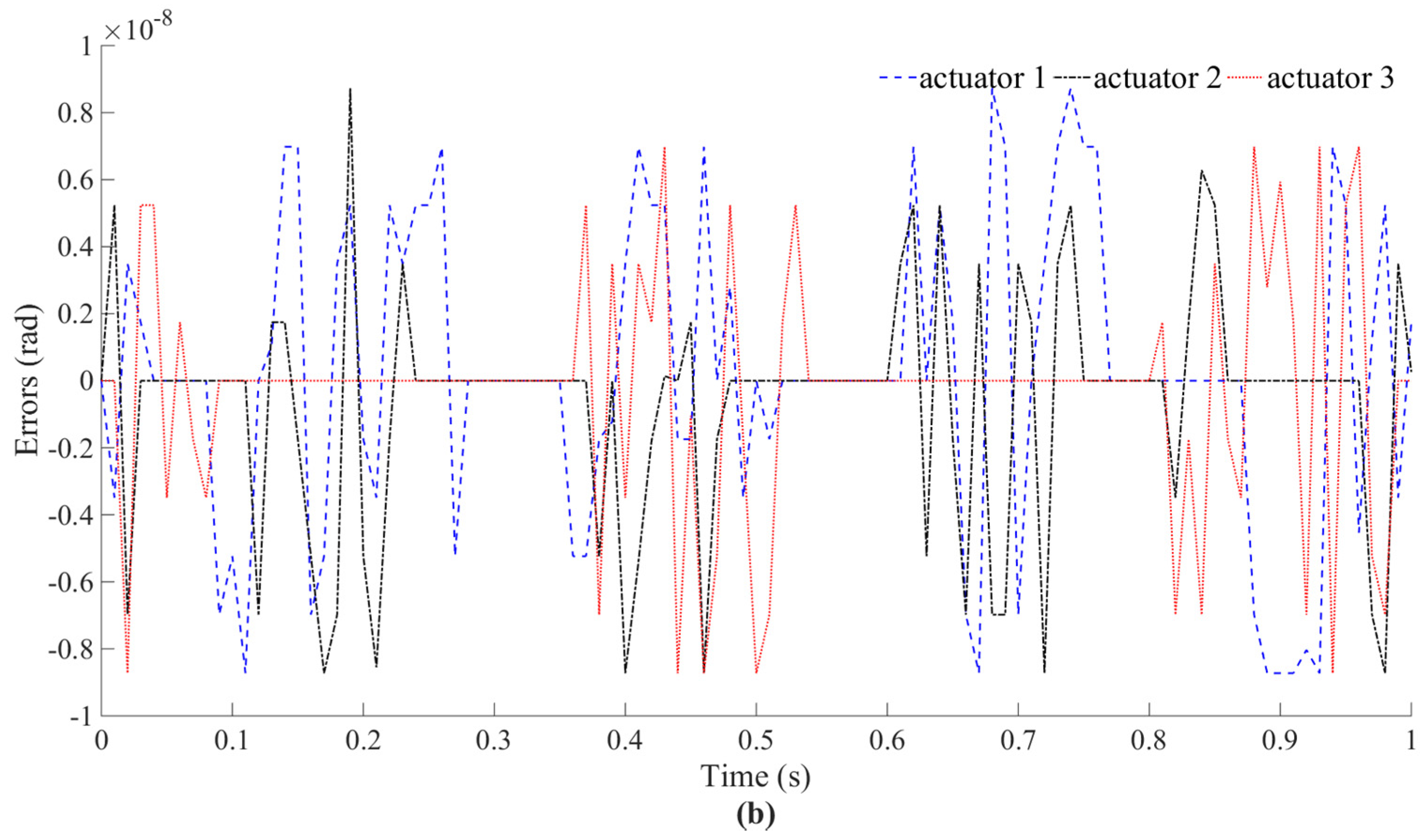
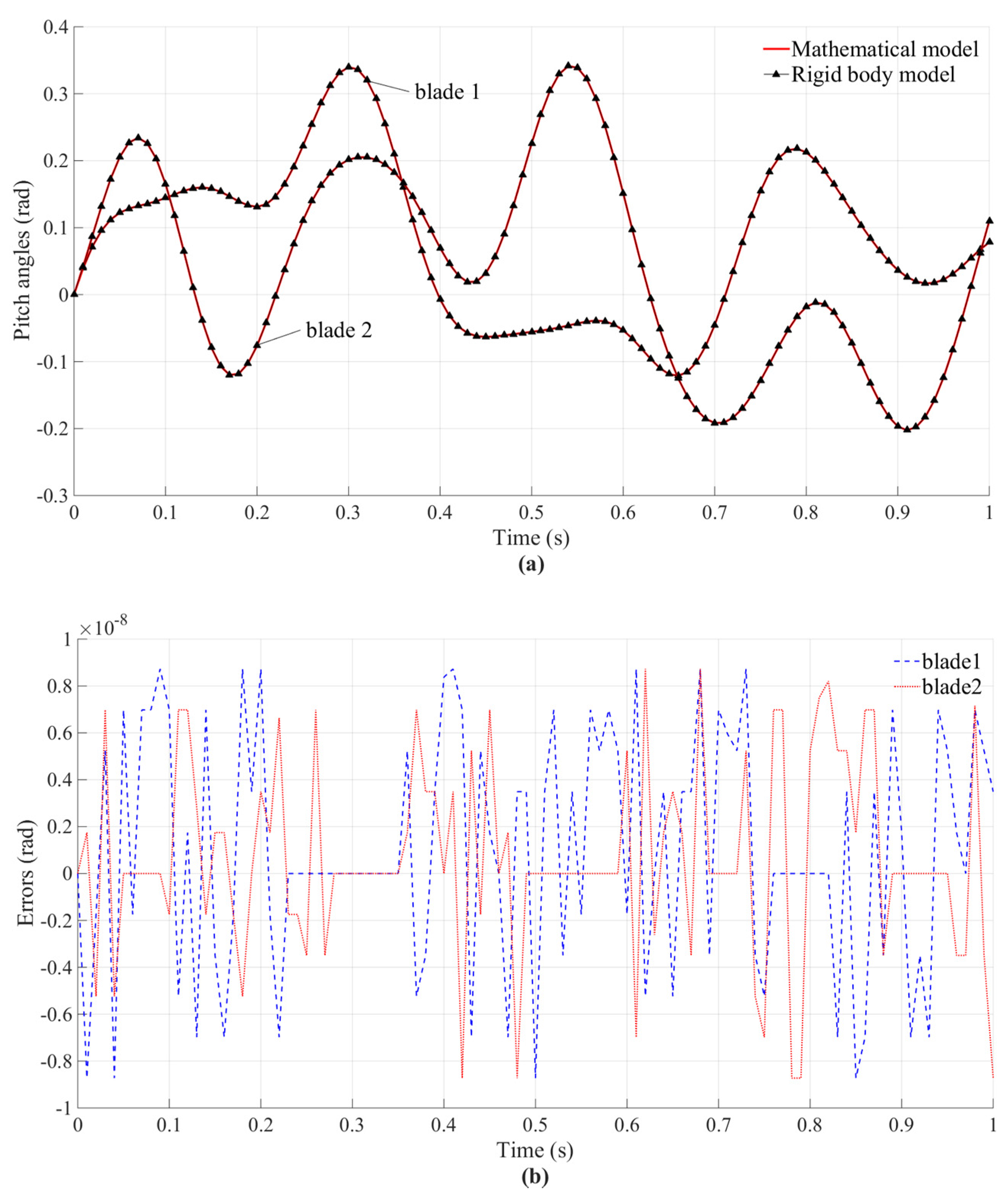
The motion considered for each actuator and the analytical results calculated through the inverse kinematic model are shown in Figure 7a. As indicated in Figure 7b, the accuracy of such a model is verified. For the direct kinematics, the simulation and analytical results of two blades’ pitch angles are shown in Figure 8a. The simulation and analytical results match well in all simulation cases. This shows that the direct kinematic model is correct. The corresponding errors shown in Figure 8b are acceptable.
To verify the inverse dynamic model and make the results more obvious, the moments generated by two blades are set in simple form instead of using the blade element theory. Additionally, through dynamic analysis, we note that the driving torque of the main shaft does not change the results in the calculating process. Therefore, the loads are given as:
τ R = [ A m sin ( π t ) cos ( π t ) A m sin ( π t π ) cos ( π t ) 0 ] Τ
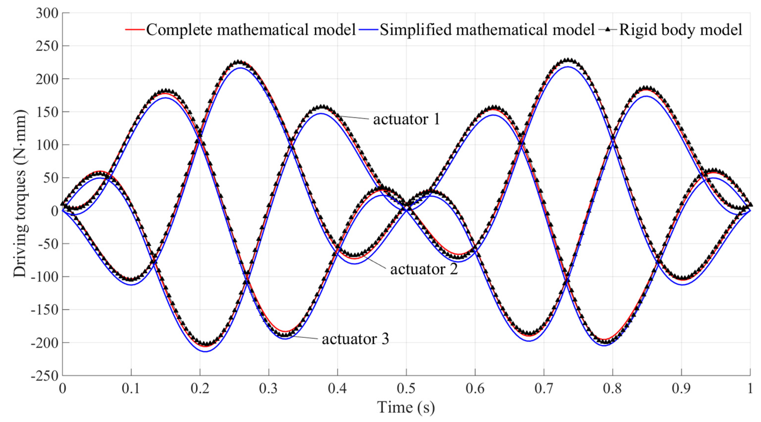
As summarized in Figure 9, for Am = 600 N·mm, the simulation results match well with the analytical results of the complete model. This verifies the correctness of the presented inverse dynamic model of the FBL swashplate mechanism.

3.2. Simulation Results and Analysis

As the inverse dynamic model has been proven to be correct, a series of simulation can be conducted for the actuators’ load analysis. As mentioned in the dynamic modeling process, the rods have been neglected. In fact, the dynamic analysis of the rods is very difficult. Thus, neglecting them simplifies the dynamic model. If other components of the swashplate mechanism are neglectable, the dynamic model will be more efficient. Therefore, we neglect all the components of the swashplate mechanism, which means the simplified model only considers the loads τ R . As shown in Figure 9, the driving torques determined with the simplified model are illustrated with blue solid curves. It can be observed that the simplified model also agrees with the rigid body model. The comparison of the results illustrates that neglecting the dynamic contribution of the rods is reasonable. From the perspective of the entire simulation process, the equilateral triangle arrangement of these three actuators realizes a uniform distribution of the load.
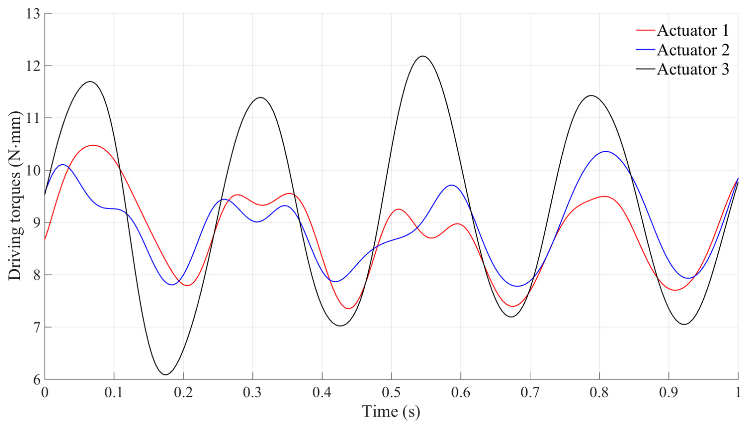
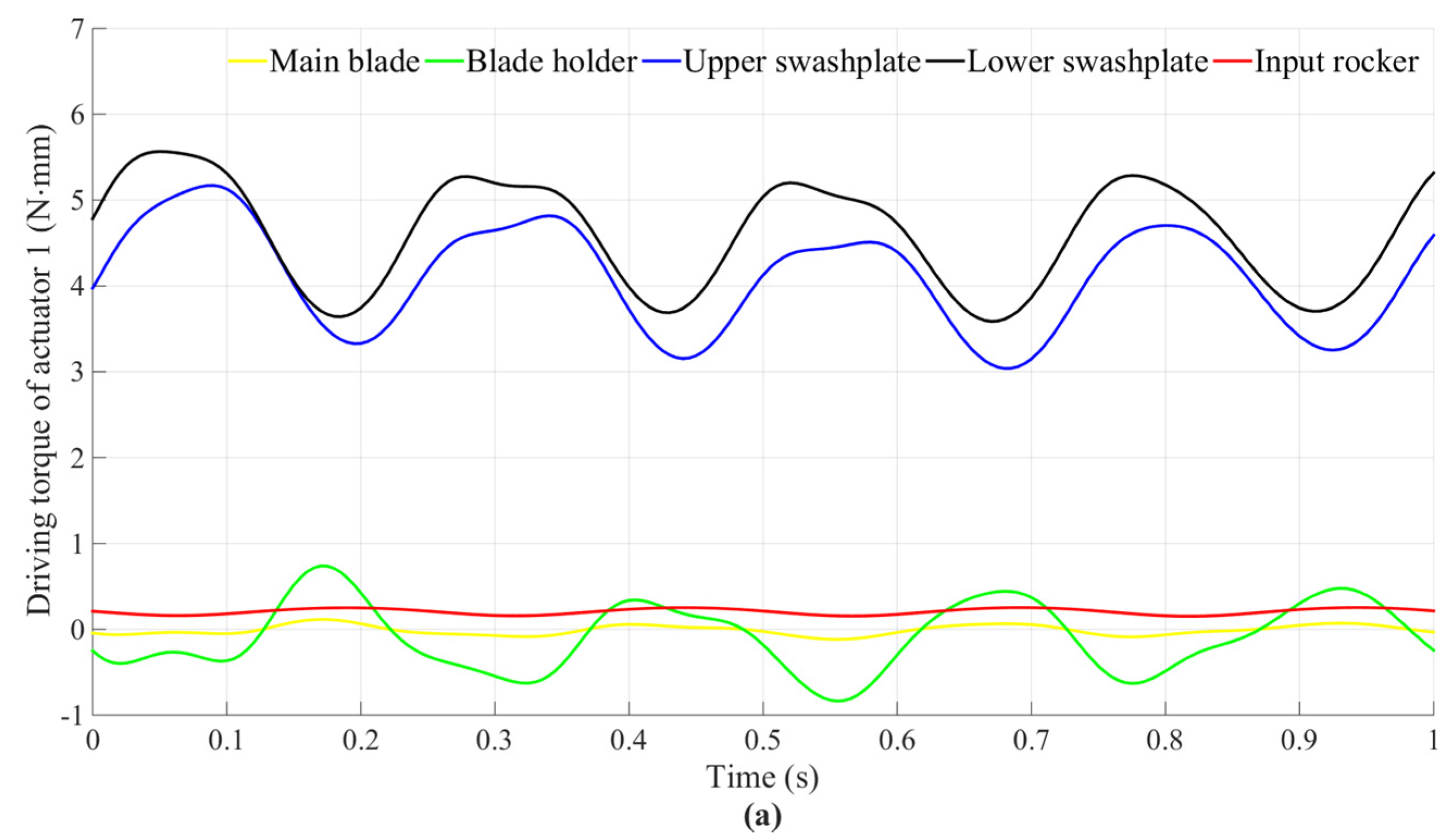
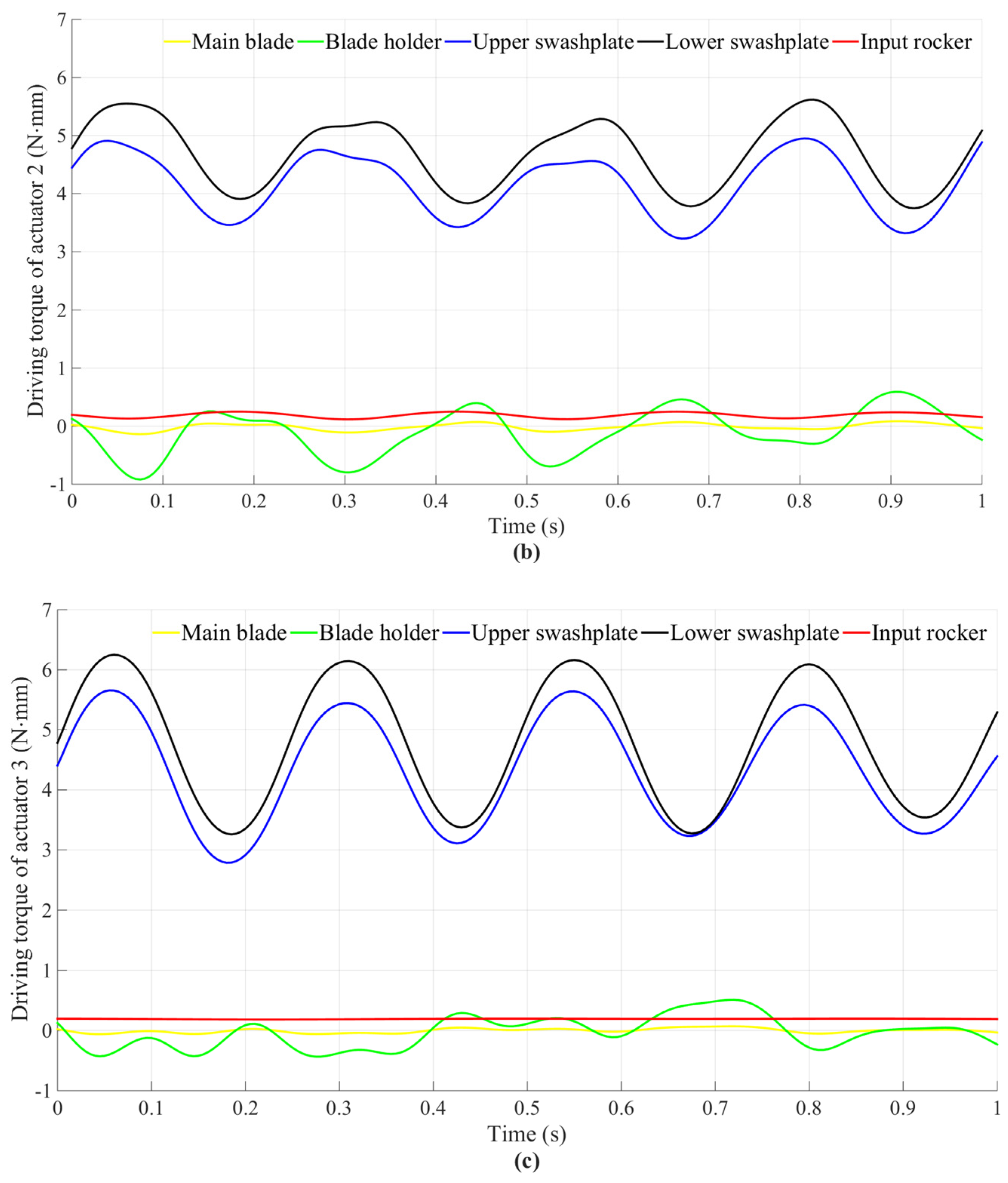
The torque contribution of the components in Equation (63) can be further analyzed; as shown in Figure 10, for Am = 0 N·mm, there is no external force exerted on the blades, and the amplitude of the torques resulting from the inertial part is quite small compared with the torques resulting from the blade loads. The torque contribution of each part of the driving torque is shown in Figure 11. Obviously, the torque contributions of the input rocker and the inertial part of the main blade are very small and the swashplate is the dominant and most violet component. Therefore, further research on the rods to improve the model accuracy is meaningless.

4. Conclusions

The kinematics and inverse dynamics of an FBL swashplate mechanism are analyzed in this paper. A novel comprehensive model is derived. An analytical model for the kinematics is built up based on the parallel robots concepts, including three levels: position, velocity, and acceleration. Based on the principle of virtual work, a novel closed-form dynamics model is established, which could be incorporated in the real-time attitude controller. Such a model provides an effective method to analyze the sources of the actuators’ load.
By comparing the Recurdyn simulation results with the analytical results derived from the mathematical model we obtained, the novel comprehensive kinematic model proved to be precise enough for the control system design. The dynamic model proved to be capable to predict the loads that acted on actuators of such a mechanism, and the dominant impact of the blade loads of the FBL swashplate mechanism on the driving torques was analyzed with a numerical simulation. From the simulation results, we could find that the aerodynamic hinge moments that acted on the rotating blades were the main sources of the actuators’ load and were the main factor to influence the oscillating dynamic loads for the three actuators. The inertial forces of the FBL swashplate mechanism components have little effect on the actuators. The simplified model may be more practical in the controller design progress, as neglecting the components makes the calculation more efficient.
In future work, combined with a complete aerodynamic rotor theory, a more in-depth research of the actuators’ loads can be done under real flight conditions, which can benefit the design of the controller of the actuator. Furthermore, the vibration characteristics of each component can be analyzed in detail. Additionally, the kinematic and dynamic model lay a foundation for the optimization of the FBL swashplate mechanism.

Author Contributions

Conceptualization, H.W. and L.H.; methodology, J.L. and Y.Y.; software, J.L.; validation, R.G. and L.H.; investigation, H.W.; resources, L.H.; data curation, J.L.; writing—original draft preparation, J.L.; writing—review and editing, Y.Y., R.G., and H.W.; supervision, Y.Y.; project administration, R.G. and L.H.; funding acquisition, Y.Y. All authors have read and agreed to the published version of the manuscript.

Funding

This work is supported by the National Key R&D Program of China (Grant No. 2017YFC0602000) and the Science and Technology Development Project of Jilin Province (Grant No. 20190303061SF).

Conflicts of Interest

The authors declare no conflict of interest. The funders had no role in the design of the study; in the collection, analyses, or interpretation of data; in the writing of the manuscript; or in the decision to publish the results.

References

  1. Raptis, I.A.; Valavanis, K.P. Linear and Nonlinear Control of Small-Scale Unmanned Helicopters; Springer: Heidelberg, Germany, 2011. [Google Scholar]
  2. Shen, J.W.; Chopra, I. Swashplateless Helicopter Rotor with Trailing-Edge Flaps. J. Aircraft. 2004, 41, 208–214. [Google Scholar] [CrossRef]
  3. Song, B.; Mills, J.K.; Liu, Y.; Fan, C.Z. Nonlinear dynamic modeling and control of a small-scale helicopter. Int. J. Control Autom. Syst. 2010, 8, 534–543. [Google Scholar]
  4. Lange, C.; Ranjbaran, F.; Angeles, J.; Goritschnig, G. The kinematics of the swashplate mechanism of a VTOL unmanned aerial vehicle. Multibody Syst. Dyn. 1999, 3, 333–365. [Google Scholar] [CrossRef]
  5. Akbarzadeh, A.; Enferadi, J.; Sharifnia, M. Dynamics analysis of a 3-RRP spherical parallel manipulator using the natural orthogonal complement. Multibody Syst. Dyn. 2013, 29, 361–380. [Google Scholar] [CrossRef] [Green Version]
  6. Lange, C.; Ranjbaran, F.; Angeles, J.; Goritschnig, G. The dynamics of the swashplate mechanism of a VTOL unmanned aerial vehicle. Multibody Syst. Dyn. 2001, 5, 105–131. [Google Scholar]
  7. Sabaapour, M.R.; Zohoor, H. Analysis of a swashplate mechanism of the hingeless rotor hub with the flybar in a model helicopter, Part I: Kinematics. Trans. Jpn. Soc. Mech. Eng. 2010, 4, 616–631. [Google Scholar] [CrossRef] [Green Version]
  8. Sabaapour, M.R.; Zohoor, H. Analysis of a swashplate mechanism of the hingeless rotor hub with the flybar in a model helicopter, Part II: Dynamics. Trans. Jpn. Soc. Mech. Eng. 2010, 4, 258–296. [Google Scholar] [CrossRef] [Green Version]
  9. Tsai, L.W. Solving the Inverse Dynamics of a Stewart-Gough Manipulator by the Principle of Virtual Work. J. Mech. Des. 1999, 122, 3–9. [Google Scholar]
  10. Khaligh, S.P.; Fahimi, F.; Koch, C.R. A fast inverse kinematic solution for the nonlinear actuating mechanisms of a small-scale helicopter. Multibody Syst. Dyn. 2015, 35, 257–275. [Google Scholar] [CrossRef]
  11. Saffarian, M.; Fahimi, F. A comprehensive kinematic analysis of a model helicopter’s actuating mechanism. In Proceedings of the AIAA Aerospace Sciences Meeting and Exhibit, Reno, NV, USA, 7–10 January 2008. [Google Scholar]
  12. Kim, S.K.; Tilbury, D.M. Mathematical modeling and experimental identification of an unmanned helicopter robot with flybar dynamics. J. Intell. Robot. Syst. 2004, 21, 95–116. [Google Scholar] [CrossRef] [Green Version]
  13. Ren, B.; Sarabia, M.; Chen, C.; Fua, C.H.; Lee, T.H. Modeling, Control and Coordination of Helicopter Systems; Springer: New York, NY, USA, 2012. [Google Scholar]
  14. AI-Sharman, M.; Abdel-Hafez, M.; AI-Omari, M. State Estimation for a Small Scale Flybar-less Helicopter. Proc. Technol. 2014, 15, 258–267. [Google Scholar] [CrossRef] [Green Version]
  15. Ding, L.; Wu, H.T.; Yao, Y. Chaotic Artificial Bee Colony Algorithm for System Identification of a Small-Scale Unmanned Helicopter. Int. J. Aerosp. Eng. 2015, 2015, 801874. [Google Scholar] [CrossRef]
  16. Yuan, X.; Zhu, J.; Chen, Z.; Lu, X.; Meng, J. Inverse dynamic modeling and analysis of a coaxial helicopter’s swashplate mechanism. Mech. Mach. Theory 2017, 113, 208–230. [Google Scholar] [CrossRef]
  17. Merlet, J.P. Parallel Robots; Springer: Heidelberg, Germany, 2006. [Google Scholar]
  18. Dasgupta, B.; Choudhury, P. A general strategy based on the Newton–Euler approach for the dynamic formulation of parallel manipulators. Mech. Mach. Theory 1999, 34, 801–824. [Google Scholar] [CrossRef]
  19. Hwang, Y. Recursive Newton-Euler formulation for flexible dynamic manufacturing analysis of open-loop robotic systems. Int. J. Adv. Manuf. Technol. 2006, 29, 598–604. [Google Scholar]
  20. Abdellatif, H.; Heimann, B. Computational efficient inverse dynamics of 6-DOF fully parallel manipulators by using the Lagrangian formalism. Mech. Mach. Theory 2009, 44, 192–207. [Google Scholar] [CrossRef]
  21. Zandron, O.S. Superconducting State in the Lagrangian Formalism of the Generalized Hubbard Model. Int. J. Theor. Phys. 2003, 42, 2103–2113. [Google Scholar] [CrossRef]
  22. Pedrammehr, S.; Nahavandi, S.; Abdi, H. Closed-form dynamics of a hexarot parallel manipulator by means of the principle of virtual work. Acta Mech. Sin. 2018, 34, 883–895. [Google Scholar] [CrossRef]
  23. Enferadi, J.; Akbarzadeh Tootoonchi, A. Inverse dynamics analysis of a general spherical star-triangle parallel manipulator using principle of virtual work. Nonlinear Dyn. 2010, 61, 419–434. [Google Scholar] [CrossRef]
  24. Rao, A.B.K.; Saha, S.K.; Rao, P.V.M. Dynamics Modelling of Hexaslides using the Decoupled Natural Orthogonal Complement Matrices. Multibody Syst. Dyn. 2006, 15, 159–180. [Google Scholar] [CrossRef]
  25. Tu, T.W. First-order form, Lagrange’s form, and Gibbs–Appell’s form of Kane’s equations. Acta Mech. 2016, 227, 1885–1901. [Google Scholar] [CrossRef]
  26. Gallardo-Alvarado, J.; Aguilar-Nájera, C.R.; Casique-Rosas, L. Solving the kinematics and dynamics of a modular spatial hyper-redundant manipulator by means of screw theory. Multibody Syst. Dyn. 2008, 20, 307–325. [Google Scholar] [CrossRef]
  27. Lin, C.-J.; Chen, C.-T. Reconfiguration for the Maximum Dynamic Wrench Capability of a Parallel Robot. Appl. Sci. 2016, 6, 80. [Google Scholar] [CrossRef] [Green Version]
  28. Tsai, L.W. Robot. Analysis: The Mechanics of Serial and Parallel Manipulators; Wiley: New York, NY, USA, 1999. [Google Scholar]
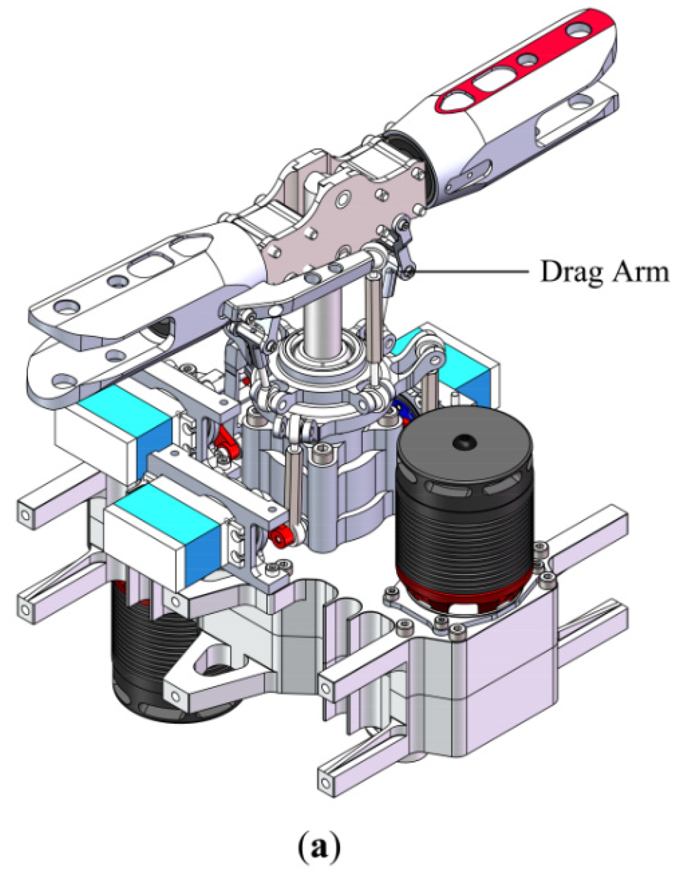
Figure 1. (a) Principle prototype of the flybar-less swashplate mechanism assembled on a platform; (b) schematic of the proposed swashplate mechanism with the essential joints.
Symmetry 12 01849 g001aSymmetry 12 01849 g001b
Figure 2. Kinematic relationship of the swashplate mechanism.
Symmetry 12 01849 g002
Figure 3. Kinematic relationship between the tilt plane and the rotor plane.
Symmetry 12 01849 g003
Figure 4. Kinematic relationship of the Rotating submodule (R-SM).
Symmetry 12 01849 g004
Figure 5. Inverse kinematics of the whole mechanism for flight control.
Symmetry 12 01849 g005
Figure 6. Global direct kinematics of the whole mechanism.
Symmetry 12 01849 g006
Figure 7. (a) Comparison of the setting motion for each actuator in RecurDyn and the analytical results obtained by the inverse kinematic model; (b) the relative errors between the mathematical model and the rigid body model.
Symmetry 12 01849 g007aSymmetry 12 01849 g007b
Figure 8. (a) Comparison of the simulation pitch angles of the two main blades and the analytical results obtained by the direct kinematic model; (b) the relative errors between the mathematical model and the rigid body model.
Symmetry 12 01849 g008
Figure 9. Comparison of the calculated torques and the simulated driving torques of three actuators. Red and blue solid lines are obtained by the proposed complete inverse dynamic model, while neglecting the rods, and the simplified inverse dynamic model, while neglecting all of the components, respectively.
Symmetry 12 01849 g009
Figure 10. The applied torques on the actuators while only the inertial forces of the components are considered.
Symmetry 12 01849 g010
Figure 11. Contributions of each component on the driving torque: (a) actuator 1; (b) actuator 2; (c) actuator 3.
Symmetry 12 01849 g011aSymmetry 12 01849 g011b
Table 1. Parameters of the swashplate mechanism.
ParametersMoment of Inertia (× 10−6 Kg·m2)ParametersLength (mm)ParametersWeight ( × 10 3 Kg)
I N R , x 13.403 L 25 m A 1 C 1 1.776
I N R , y 26.591 c A 1 C 1 12.02 m A 2 C 2 1.702
I N R , z 13.403 c A 2 C 2 11.73 m A 3 C 3 1.702
I R , x 9.462 c A 3 C 3 11.73 m b h 85.56
I R , y 19.117 r 44.5 m R 52.32
I R , z 9.793 H = H R 60 m N R 58.53
I b h , x 23.282 L R 30
I b h , y 26.780 r R 30
I b h , z 6.316 c b , x 1.68
I b , x 793.943 c b , z 54.74
I b , y 794.929 l B i C i 60
I b , z 1.048 l E i D i 60
Publisher’s Note: MDPI stays neutral with regard to jurisdictional claims in published maps and institutional affiliations.