Article

Vacant Parking Slot Recognition Method for Practical Autonomous Valet Parking System Using around View Image

1
Department of Electronics and Computer Engineering, Hanyang University, Seoul 04763, Korea
2
LightVision Inc., Seoul 04793, Korea
*
Authors to whom correspondence should be addressed.
Symmetry 2020, 12(10), 1725; https://doi.org/10.3390/sym12101725
Submission received: 1 September 2020 / Revised: 23 September 2020 / Accepted: 15 October 2020 / Published: 19 October 2020
(This article belongs to the Special Issue Symmetry in Computer Vision and Its Applications)

Abstract

:
The parking assist system (PAS) provides information of parking slots around the vehicle. As the demand for an autonomous system is increasing, intelligent PAS has been developed to park the vehicle without the driver’s intervention. To locate parking slots, most existing methods detect slot markings on the ground using an around-view monitoring (AVM) image. There are many types of parking slots of different shapes in the real world. Due to this fact, these methods either limit their target types or use predefined slot information of different types to cover the types. However, the approach using predefined slot information cannot handle more complex cases where the slot markings are connected to other line markings and the angle between slot marking is slightly different from the predefined settings. To overcome this problem, we propose a method to detect parking slots of various shapes without predefined type information. The proposed method is the first to introduce a free junction type feature to represent the structure of parking slot junction. Since the parking slot has a modular or repeated junction pattern at both sides, junction pair consisting of one parking slot can be detected using the free junction type feature. In this process, the geometrically symmetric characteristic of the junction pair is crucial to find each junction pair. The entrance of parking slot is reconstructed according to the structure of junction pair. Then, the vacancy of the parking slot is determined by a support vector machine. The Kalman tracker is applied for each detected parking slot to ensure stability of the detection in consecutive frames. We evaluate the performance of the proposed method by using manually collected datasets, captured in different parking environments. The experimental results show that the proposed method successfully detects various types of parking slots without predefined slot type information in different environments.

1. Introduction

The parking assist system (PAS) [1] aims to assist drivers in parking their vehicles easily by providing useful information such as parking slot, pedestrians, and vacant space. The PAS generally highlights the parking area around the vehicle and sends the location of available parking slots to the driver. In recent times, the demand for an autonomous decision-making process has begun to rise with the advent of industry 4.0 [2]. Therefore, the intelligent PAS, which automatically parks the vehicle to an empty parking area without the driver’s control, has been actively studied. With the intelligent PAS, the vehicle can detect parking slots around it by using mounted sensors and cruise into an empty slot among the detected slots. The process of detecting an empty parking slot is divided into three steps: information acquisition around the vehicle, parking slot detection, and classification of empty parking slots. Among them, the parking slot detection can be categorized into two types: the free-space-based method and the slot-marking-based method.
The free-space-based method can find the empty parking slot in between two occupied parking slots by detecting adjacent vehicles. To detect the adjacent vehicles, range-finding sensors, such as ultrasonic or laser scanners are used. However, if there are no vehicles on both the sides of the target parking slot, this method cannot locate the empty parking slot properly. In addition, estimated position and direction of the empty parking slot highly depend on the parking conditions of the adjacent vehicles.
The slot-marking-based method locates parking slots by detecting parking slot markings on the ground by using imaging sensors. This method can detect any parking slots if the parking slot markings are predefined and visible in the image disregarding the existence of the adjacent vehicles near the target parking slot.
Between the two types of parking slot detection method, we focus on implementing a slot-marking-based method by considering following reasons: (1) cost effectiveness of image sensors and (2) popularity of image-based around-view monitoring (AVM) systems.
In general, the slot-marking-based method consists of three steps: junction location detection, parking slot type classification, and parking slot generation by combining multiple junctions. To detect the location of junctions, existing methods either calculate the cross point of the parking slot lines, detect corner points, or find predefined junction templates in the image. However, the corner detection algorithm cannot provide junction location accurately in partially occluded or contaminated slot junctions, and the template matching can only detect limited types of slot junctions. To classify the parking slot types, existing methods define several junction types and find matched junctions among the predefined types by comparing their appearance. Then, the parking slot is generated by combining predefined junction pairs, as shown in Figure 1. The slot types can be defined according to the junction types composing entrance shape of parking slot. For example, TT slot means that the entrance of parking slot consists of two T-shaped junctions. Generally, TT slot is called rectangular parking slot, TL is slanted parking slot, T’T’ is rectangular parking slot for parallel parking, YY is diamond parking slot, and II is open parking slot.
At this point, a big problem arises because there are countless variations of the parking slots having different slot-markings at junctions in the real-world environment. For example, parking slots for people with disabilities, slanted parking slots that have different slot line angles, parking slots without guide lines, etc.
Since it is almost impossible to enumerate and predefine all types of junctions, we introduce a parking slot detection method using a new feature that can represent various types of junctions, called free junction type feature. The free junction type features contain the location of junction and multiple lane directions at which the slot lane exists. After generating free junction type features, these are paired by considering their location and directions to reconstruct parking-slot entrance and shape. Then, the entrance and shape information are utilized to set the region of interest for examining a vacancy of the detected slot. The histograms in the Lab color space and support vector machine (SVM) are adopted to determine whether parking slots are vacant or not.
The proposed method can detect the junctions of undefined shapes because the slot lane directions of the free junction type feature are altered depending on the shape of the junctions. Figure 2 illustrates examples of detecting a modified parking slot using a pair of free junction type features. In summary, the proposed method has the following virtues:
  • While detecting location of parking slot junctions, the proposed method utilizes both parking slot line and its corner information; therefore, it is robust to locational errors of the corner detection induced from occluded or broken slot lines.
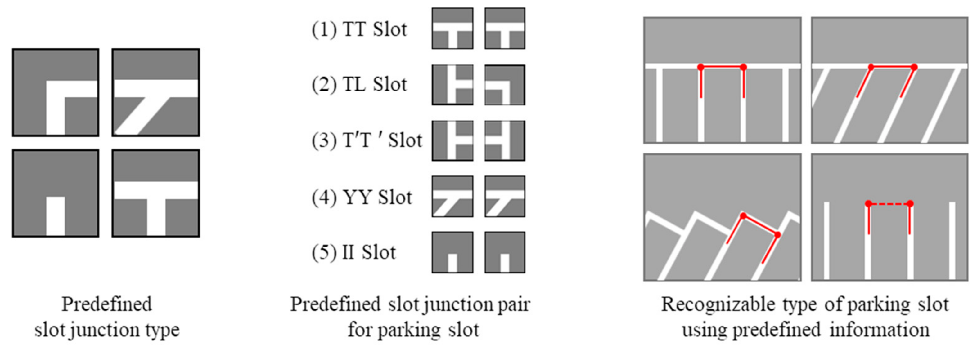
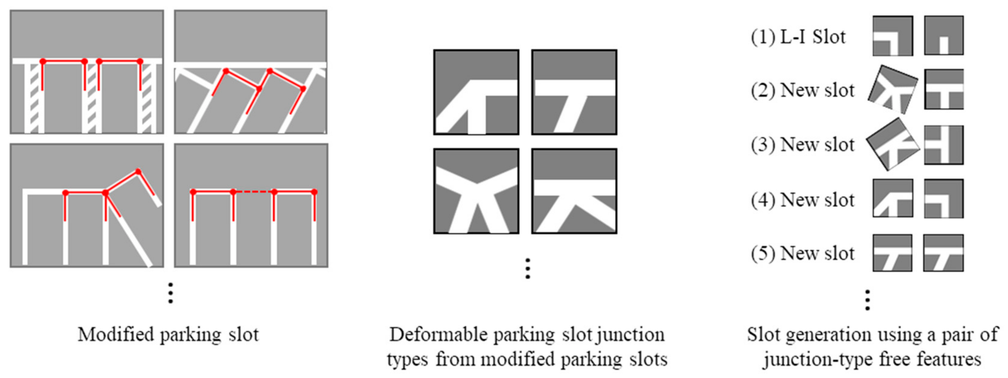
  • Unlike the existing slot junction features, the proposed method can effectively represent the modified shape of parking slots due to deformable characteristic of the proposed free junction type features.
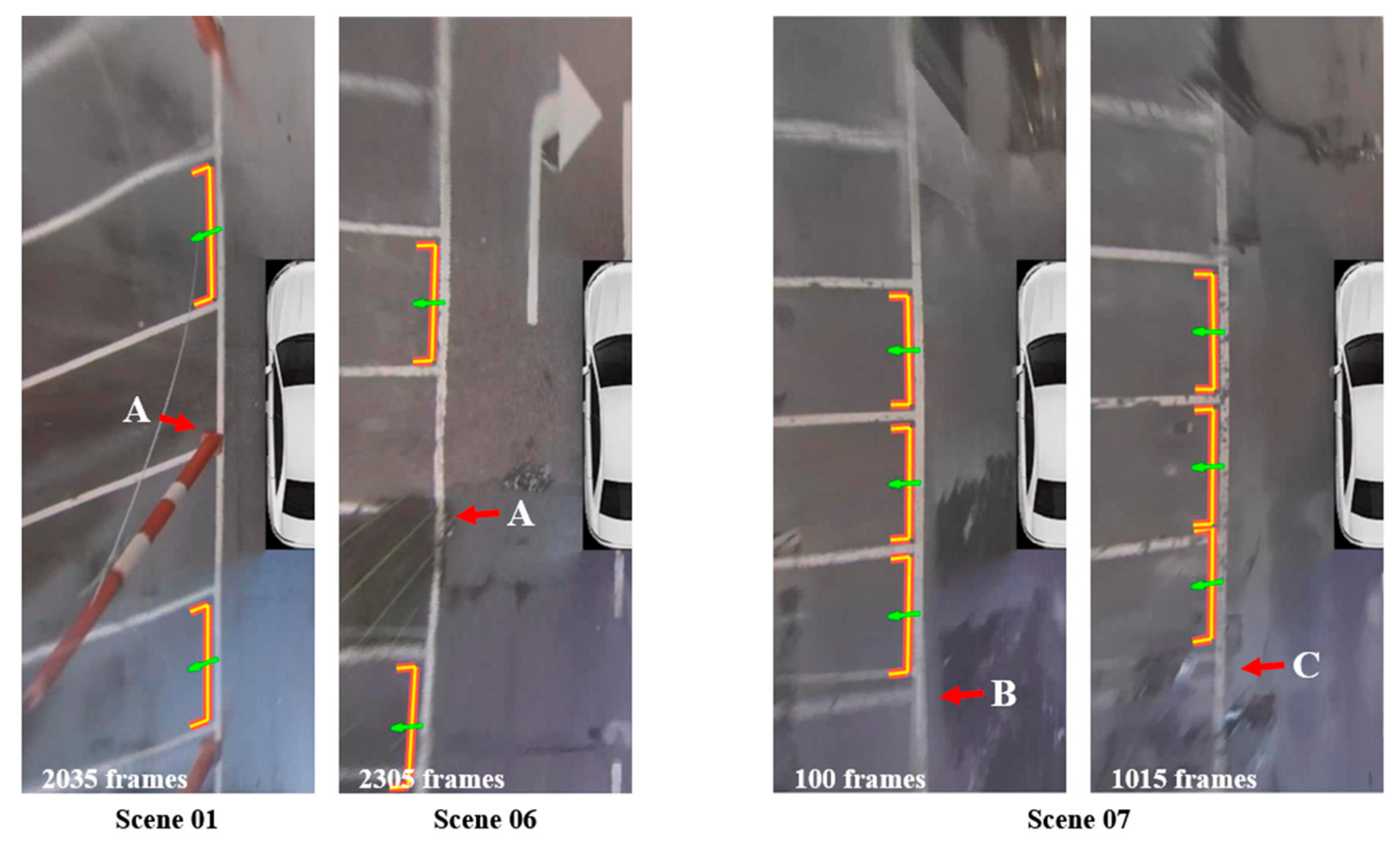
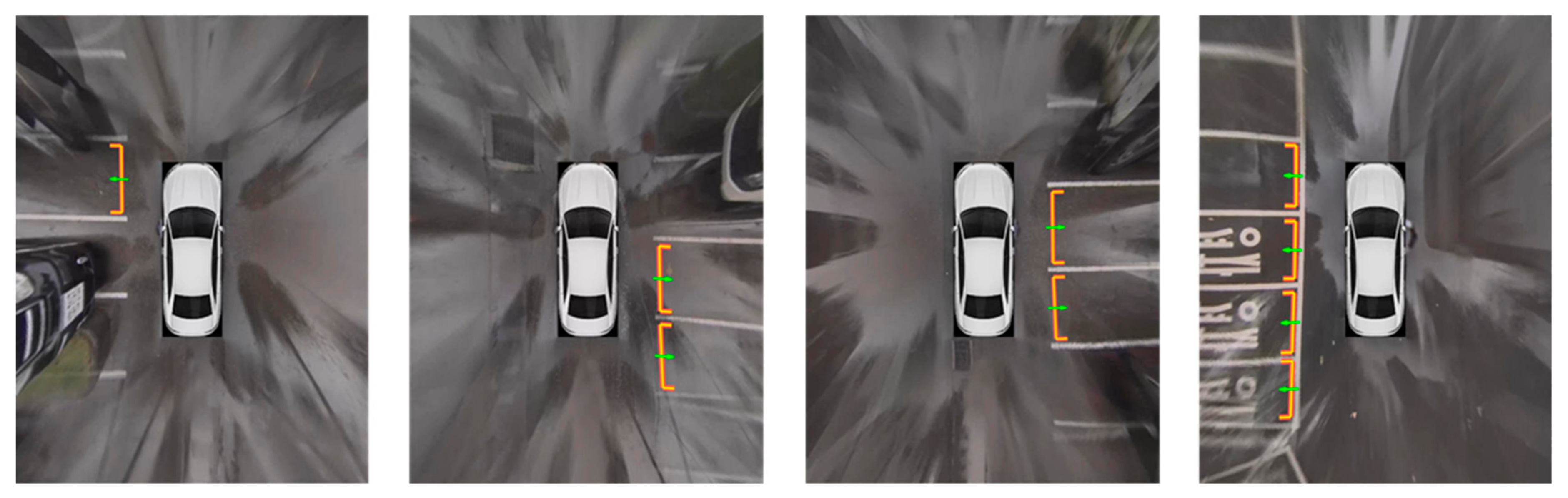
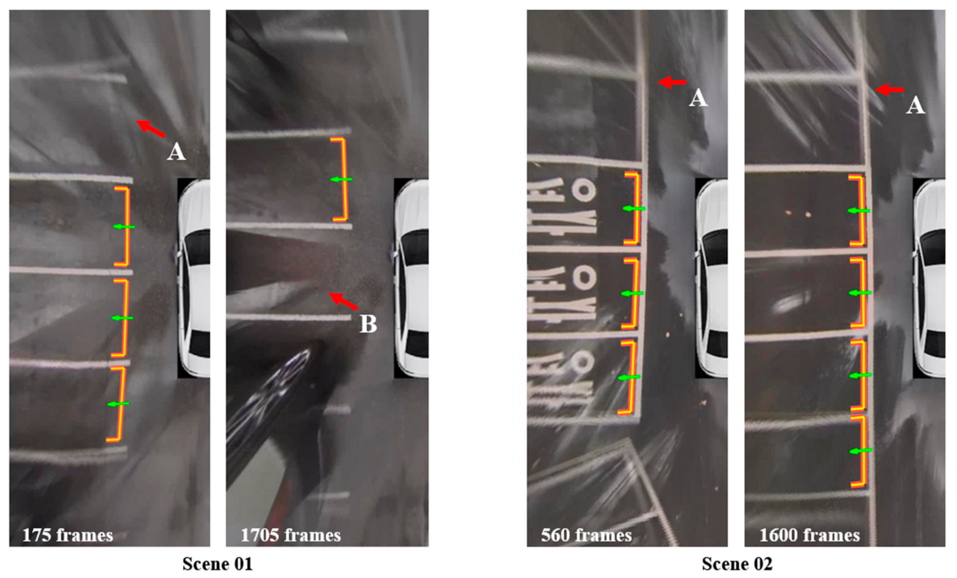
  • The performance of the proposed method is evaluated through extensive experiments in different parking environments. The experimental results show that the proposed method can detect parking slots regardless of the weather changes and different shapes of the parking slot.
The remainder of the paper is organized as follows: Section 2 describes the existing literature related to the proposed method. Section 3 presents the proposed parking slot detection method. Section 4 describes the experimental results. We conclude our paper in Section 5.

2. Related Work

The slot-marking-based methods to detect parking slots can be grouped into two: (1) parking slot line marking-based method and (2) parking slot marking corner-based method.

2.1. Parking Slot Line Marking-Based Method

The parking slot line marking-based method detects line markings of parking slots and combines them to recognize shape and position of each parking slot. To do this, many filters are introduced to extract high response values at slot markings in the image. Most of these filters are designed to consider a predefined width of the slot marking [3] into account. In addition, the top-hat filter [4], ridge filter [5], and cone hat filter [6] are designed with the idea that the slot markings are brighter than background pixels. The main goal of these filters is to detect the center positions of the slot markings. On the other hand, there are studies that have used the Canny edge detector [7] or intensity gradient [8,9,10,11] to extract boundaries between the slot markings and background. After obtaining a response map for the slot markings, the parking slot line segment is extracted using either random sample consensus (RANSAC) [5,10,11], Hough transform [12,13], or Radon transform [7].
Jung et al. [13] tried to detect a rectangular parking slot using the Sobel edge filter and Hough transform. Since the slot marking has two parallel lines, butterfly patterns appear as a pair and are spaced equal to the width of slot marking in Hough space. They focused on this characteristic and introduced a specialized filter to detect the pattern. As an advanced piece of work, Suhr and Jung [10] presented a parking slot detection method using positive and negative edges. Using the geometric property that a slot marking forms two parallel lines having positive and negative edges in the Sobel filtered image, RANSAC is performed to extract a guideline segment. Then, segment lines are detected by utilizing a modified version of chamfer matching.
Wang et al. [7] used the Canny edge detector and Radon transform to detect parking lines. In Radon space, angle histogram and K-means clustering are utilized to find local maxima, which are slot marking candidates in the image.
In order to accurately detect bent slot markings induced by a distortion of the fish-eye lens, the directional density-based spatial clustering of applications with noise (D-DBSCAN) clustering method is introduced by Lee et al. [4]. This method uses the top-hat filter to extract line features from gray-scale images. Then, the D-DBSCAN algorithm is applied to obtain line segments by analyzing whether the distribution of the line features in the local window has a tendency toward a specific direction.
If a single slot marking is partially occluded by other objects, the slot marking can be detected as multiple line segments. To refine those results, two clustering methods have been introduced: segment labeling [9] and entropy-based clustering [6]. Additionally, there are methods [4,11] to recognize slanted and diamond-type parking slots, to overcome the weakness of existing line marking-based methods that can only detect rectangular parking slots.

2.2. Parking Slot Marking Corner-Based Method

The slot marking corner-based method locates parking slots by detecting parking slot junctions present at both ends of a parking slot entrance. Since the shape of the junction is different according to the type of parking slot, its type can be estimated by analyzing the shape of the junctions.
To detect various types of parking slots, Jung et al. [14] defined junction templates which compose a rectangle, uneven, open, slanted, and diamond types of parking slots and classified the type of parking slot by using the template matching. This work adopted a semi-automatic process; if the user selects two junctions where he or she wants to park on the AVM image, the parking slot detection process is operated based on the location of junctions provided by the user. As an updated version of the previous study, Suhr et al. [15] proposed a fully automated parking slot detection method. Instead of the user selection, the system detects each location of the junction using Harris corner detector. After extracting corner locations, the intensity profile around each location is obtained to classify the type of junction by comparing it with the predefined templates.
Machine learning also has been applied to enhance the detection performance for various types of parking slots. Li et al. [16] trained AdaBoost to detect junctions using the sliding window scheme on the entire AVM image. After the junction detection, Gaussian line templates are applied to each junction to examine slot marking directions around them. Then, the junctions are combined by a predefined rule to reconstruct an entrance of each parking slot.
The line-based method is robust to partial occlusion and noise due to the global line fitting process. However, it is inadequate to recognize various types of the parking slot since the line fitting usually does not provide the location of both ends; it needs an additional process to obtain such information. On the other hand, the corner-based method is convenient to analyze the slot types, but the algorithms used to detect corner points in the image are vulnerable to noise and partial occlusion. Taking the advantages of both methods, our method detects line candidates and then generates free junction type features consisting of cross points and end points obtained from the line candidates. This scheme allows us to be robust to noise and detect various types of parking slot without predefined junction or slot types.

3. Proposed Method

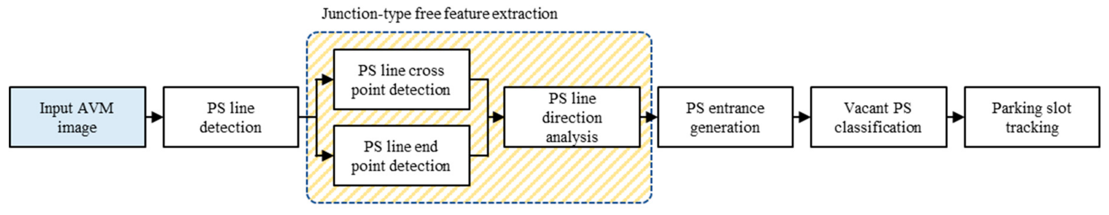
3.1. System Overview

The terms frequently used in this paper are described in Figure 3.
Parking slot is defined as a space surrounded by two segment lines and one or two guide lines with sufficient space to accommodate a vehicle. The frontal guide line and parking slot junction are located at the entrance of the parking slot. Due to the limited field of view of the AVM image, their shape and pose give an important clue to estimate the type and position of the parking slot. Therefore, we propose a method that detects parking slots by analyzing the parking slot junction. To do this, we introduce a new concept of a free junction type feature, which can effectively represent the structure of the parking slot junction. The proposed parking slot detection method is illustrated in Figure 4.
First, the proposed method detects all parking slot line candidates from the AVM images. To extract free junction type features, the proposed method combines the parking slot line candidates. The free junction type feature extraction process is divided into two parts: (1) cross and end points detection of parking slot lines and (2) slot line direction analysis. The junction-type feature is assigned to each cross point and end point, then each direction of lines connected to the junction-type feature is analyzed and embedded in each feature. After obtaining the free junction type features, the parking slot entrance is generated using a pair of free junction type features that satisfies a geometrical relationship. To select available parking slots, each detected parking slot is classified using a detector which determines the vacancy of the detected slot. Finally, a tracker is applied for each vacant parking slot.

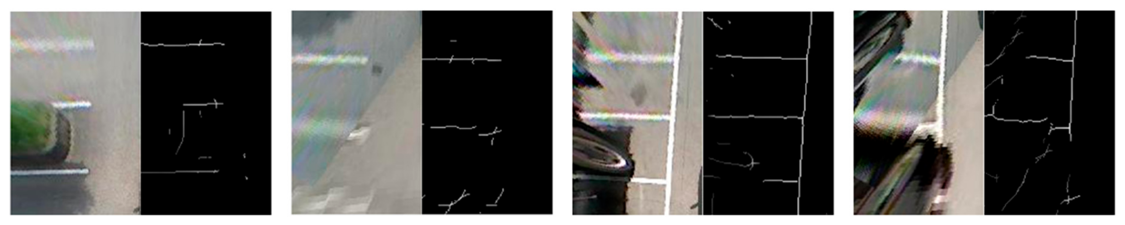
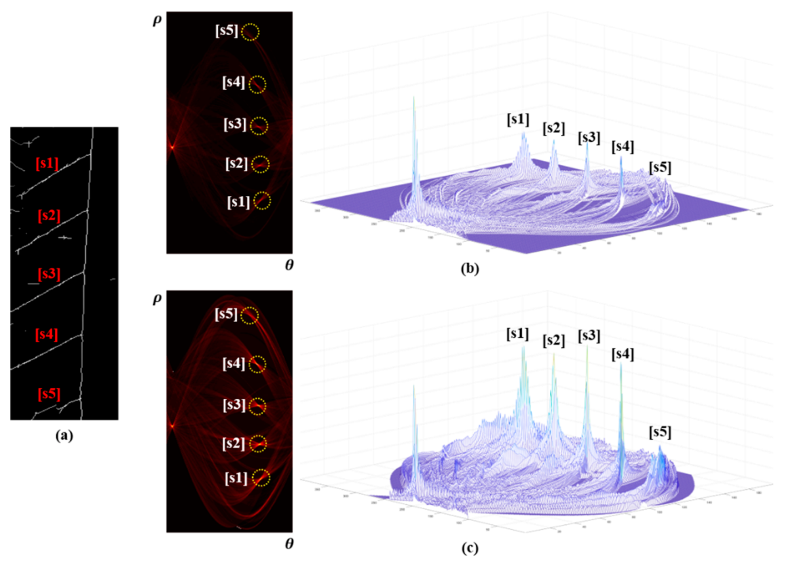
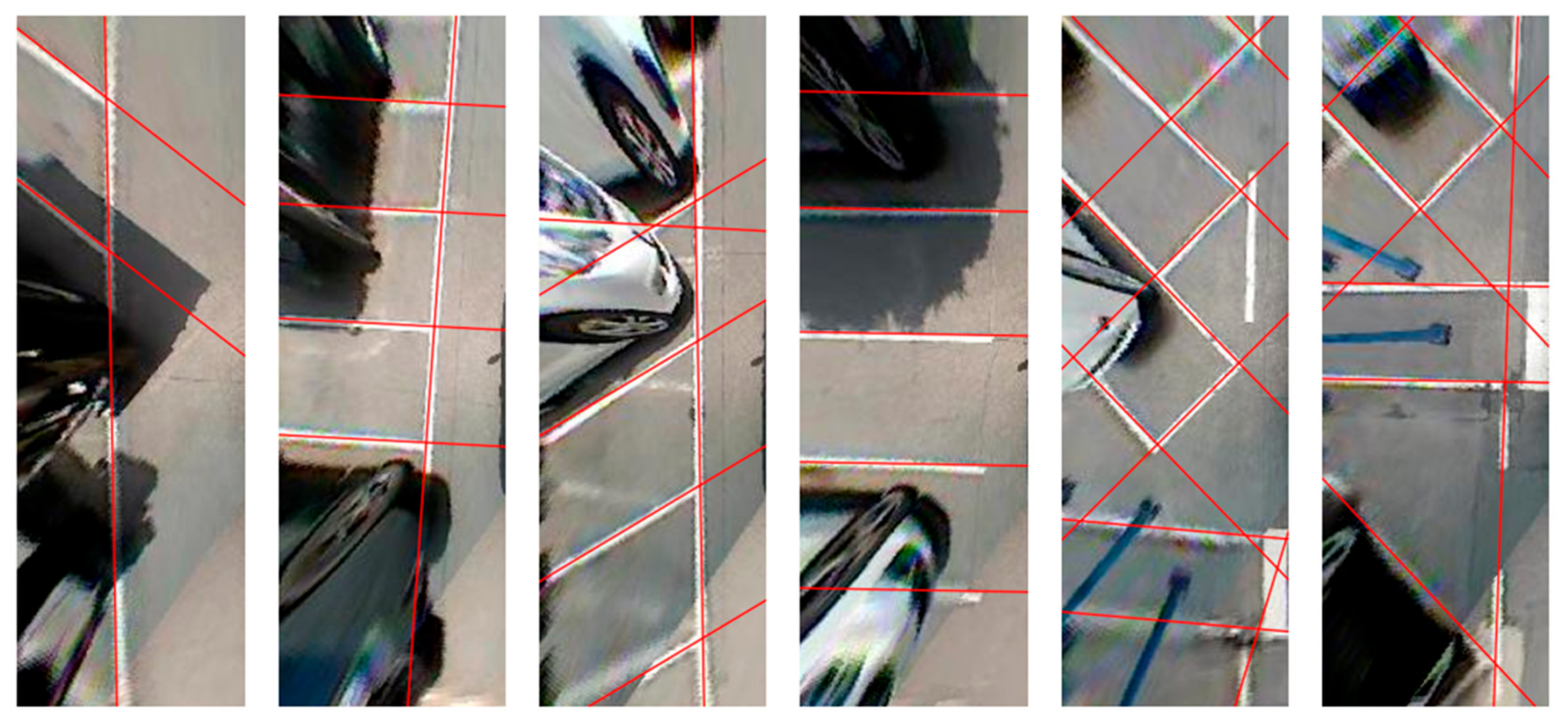
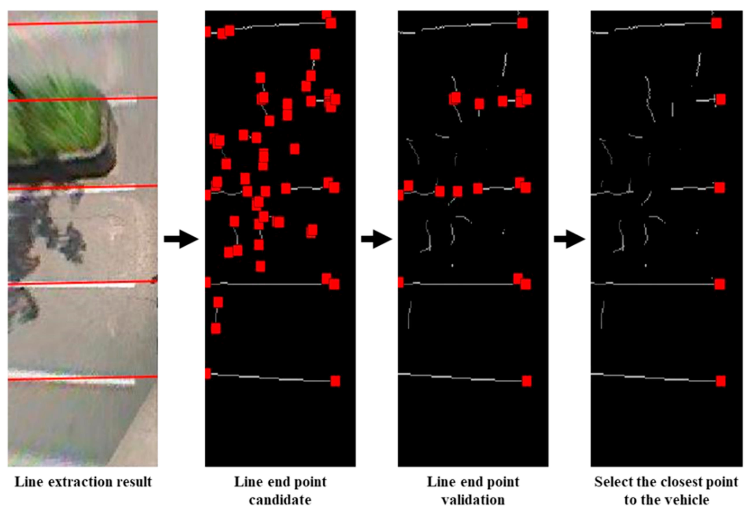
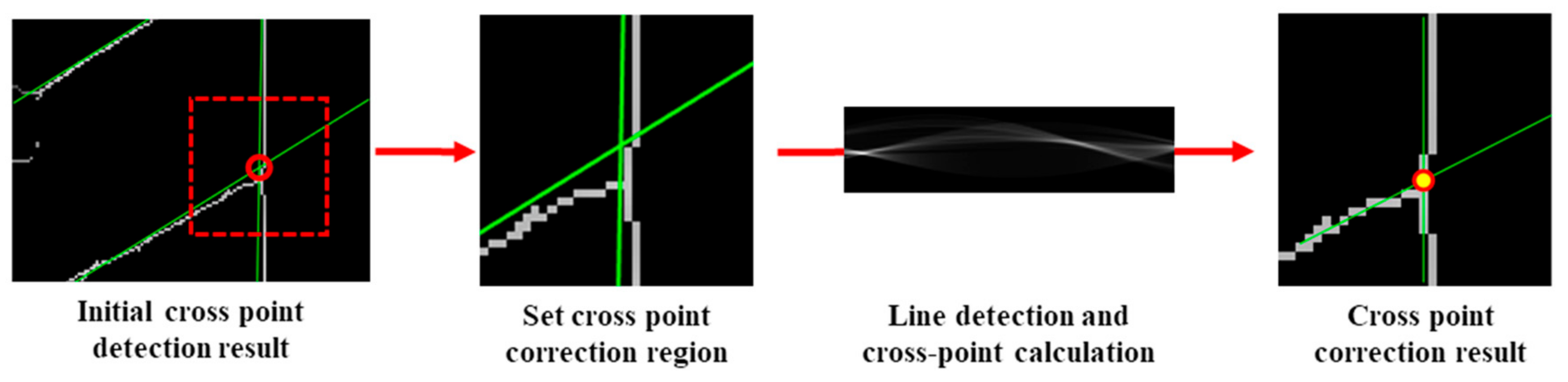
3.2. Parking Slot Line Detection

To detect the parking slot line, we obtain an initial line response map using line filters [17] as shown in Figure 5. Then, we binarize the initial line response map as a pre-processing for line fitting.
After the binarization, the proposed method obtains line candidates of parking slots in Radon space [18] by modifying Wang’s method [7]. First, we normalize the results of the Radon transform using the length of the line, where the normalized Radon transform is called as the length-normalized Radon transform. Because the height of an AVM image is longer than its width, the response of the Radon transform of the parking line in the vertical direction is higher than that in the horizontal direction. Therefore, the normalization is necessary to alleviate the problem that the parking line in the horizontal direction of the AVM image is difficult to detect in the Radon transform. As shown in Figure 6, the responses of horizontal parking lines in the normalized Radon space have a higher contrast than those in the original Radon space. Then, the line candidates are obtained using the normalized Radon transform. Before finding the local maxima in the whole Radon space to detect line candidates, we first determine theta values to reduce the search area, where line candidates are detected. Since the parking slot consists of one or two parking lines and each parking slot has the same pose and shape in the parking lot, this pre-processing is crucial to reduce duplicated line candidates. To determine the theta values, we project all values in the Radon space onto the theta-axis. Local maxima in this projection space are considered as the theta values of the line candidates. Using the obtained theta coordinates, the search area is significantly reduced from the whole Radon space to few columns in the Radon space. Then, line candidates are detected from each column of Radon space.
Figure 7 shows the line candidate detection results; parking slot lines which are short, and partially occluded by the vehicle or shadow can be accurately detected.
Let l i denote the i th parking slot line candidate and l i is defined as
l i = θ i ,   ρ i ,
where θ i and ρ i are the line angle and rho value in the Radon space, respectively.

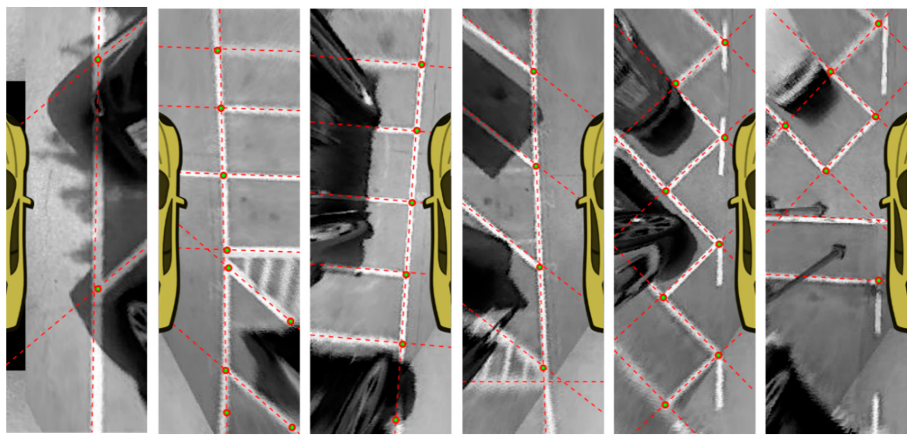
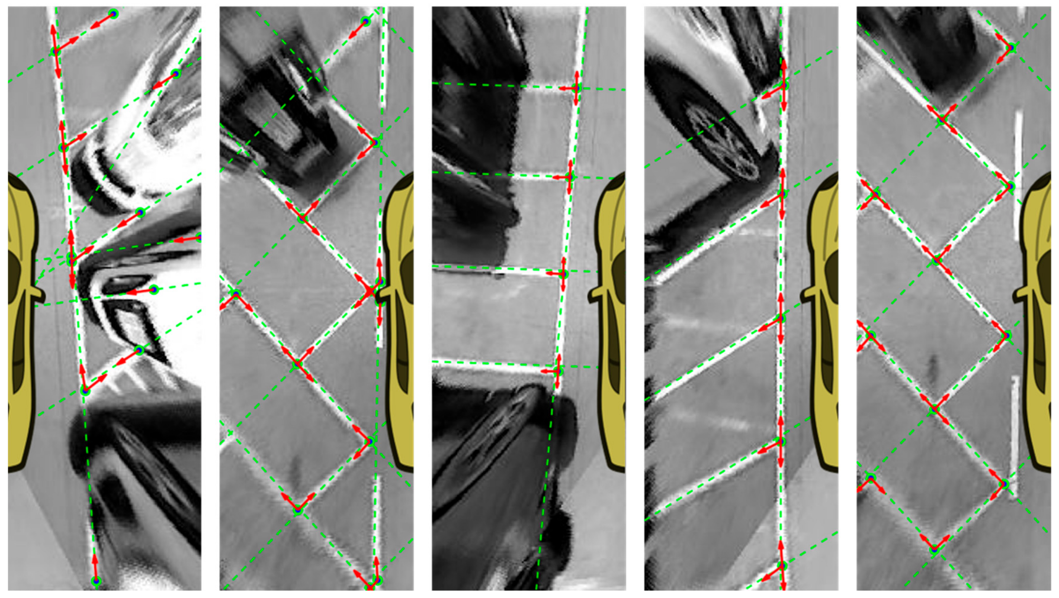
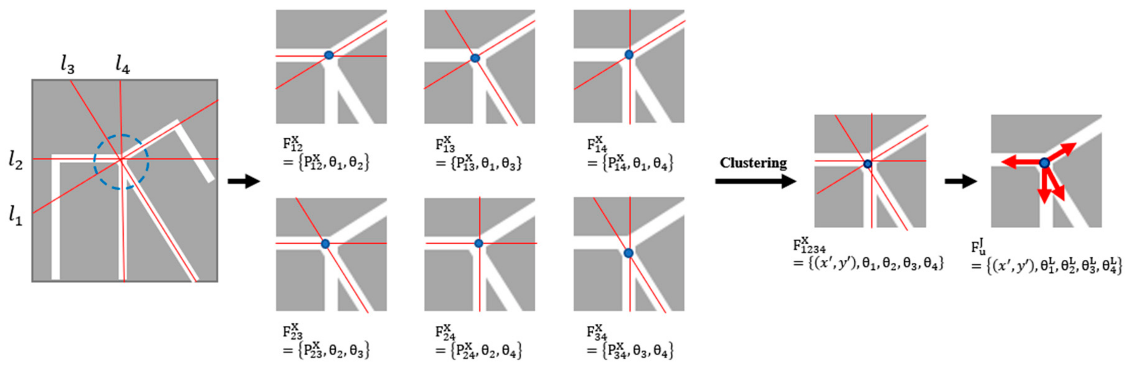
3.3. Free Junction Type Feature Extraction

In this section, we describe the free junction type feature extraction process to reconstruct the entrance of the parking slot. The free junction type feature is extracted from the parking slot junction, which can be categorized into two types, as summarized in Table 1.
We detect the location of all parking slot junctions in the AVM image by calculating the cross and end points of the parking slot line candidates. In comparison with other junction detection methods using a corner detector, the proposed method can detect partially contaminated or occluded junctions more accurately due to the global line fitting used to obtain the line candidates. The cross points are all possible intersections that can be obtained from combinations of two lines among the line candidates. Let F i j X denote the cross point of the parking slot line calculated from the i th and j th line candidates and F i j x is defined as
F i j X = P i j X , θ i X , θ j X ,
where P i j X is the pixel location and θ i X and θ j X are the line angles of l i and l j . If two lines are parallel, the cross point cannot be calculated; otherwise, the cross point can be calculated as
P i j X = ρ i sin θ j X ρ j sin θ i X sin θ j X θ i X , ρ j cos θ i X ρ i sin θ j X sin θ i X θ i X ,           i f sin θ j X θ i X 0 .
The results obtained from the cross point calculation are shown in Figure 8.
Since the end point can be generated by a single line, end points are obtained from each line candidate. Let F i E denote the end point of the parking slot line and F i E is defined as
F i E = P i E ,   θ i E ,
where P i E is the pixel location and θ i E is the line angle of l i . To calculate P i E , we first detect points using the morphological operation [19] in the line response map. Then, points located within a certain distance from each line candidate become end point candidates. Finally, among the end point candidates, a point closest to the vehicle is selected as a final end point of the line candidate. The end point detection process is illustrated in Figure 9.
The free junction type feature F u J is represented by
F u J = P u J , θ u J ,
where P u J is the pixel location of the free junction type feature and θ u J represents a set of angles for line candidates around P u J . Free junction type features are generated using the location of cross and end points; P u J is equivalent to P i j X or P i E . When considering P u J as a reference point, one line passing through the P u J can be expressed as two angles with a difference of 180 degree. Therefore, if F u J has two line candidates, θ i and θ j , at P u J , θ u J can have at most 4 angles θ i X , θ i X + π , θ j X , θ j X + π . To determine exact line directions from P u J , line direction analysis is performed by examining the direction of line candidates around the P u J as described in Figure 10. The free junction type feature shows the structure of parking slot junction as shown in Figure 11.

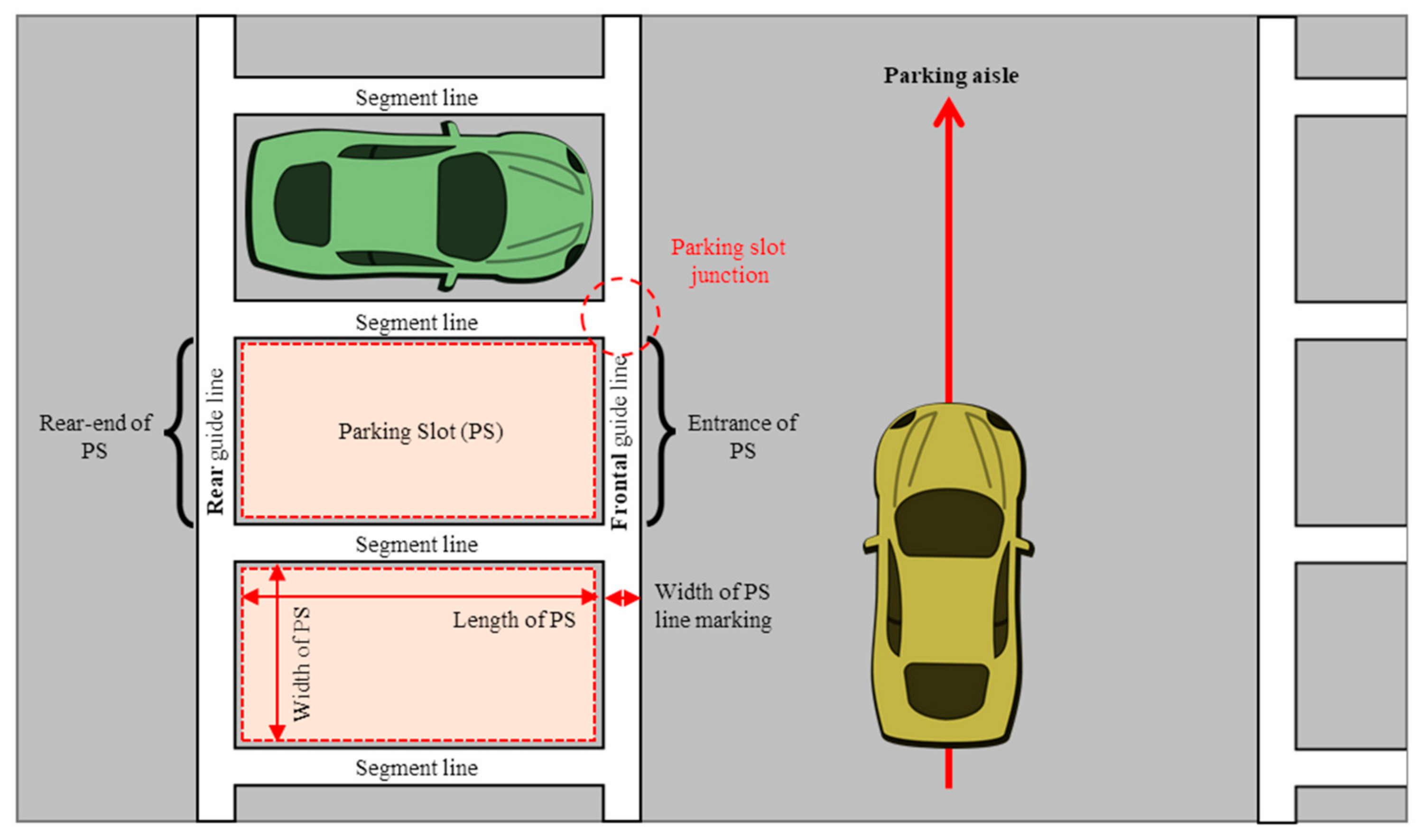
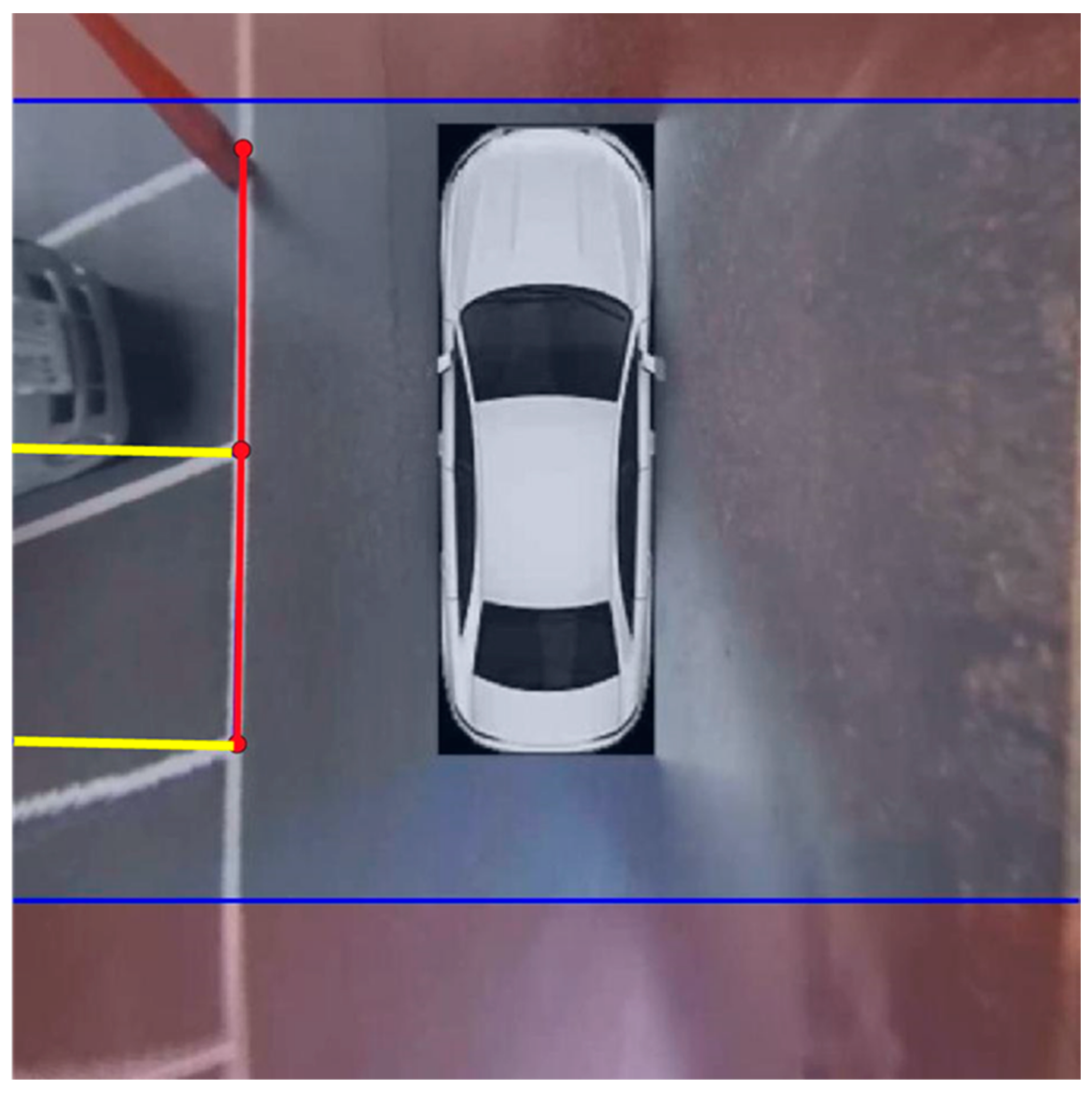
3.4. Parking Slot Entrance Generation

In this section, we describe the process of the parking slot entrance generation using a pair of free junction type features. The parking slot entrance generation process can be summarized as follows:
  • Select two free junction type features, F u J and F v J .
  • Remove the angle element having a direction facing each other for each F u J and F v J . The remaining set of angles is denoted as θ u J and θ v J .
  • Pair angle elements having similar direction in θ u J and θ v J . In this process, the angle element whose direction is toward the vehicle is excluded.
  • Calculate the length between F u J and F v J , and select the pair of free junction type features whose length is longer than the vehicle width.
  • Define the parking slot entrance using the selected pair of free junction type features.
The results of the parking slot entrance generation are shown in Figure 12. Our method accurately reconstructs parking slot entrances consisting of various junction types.

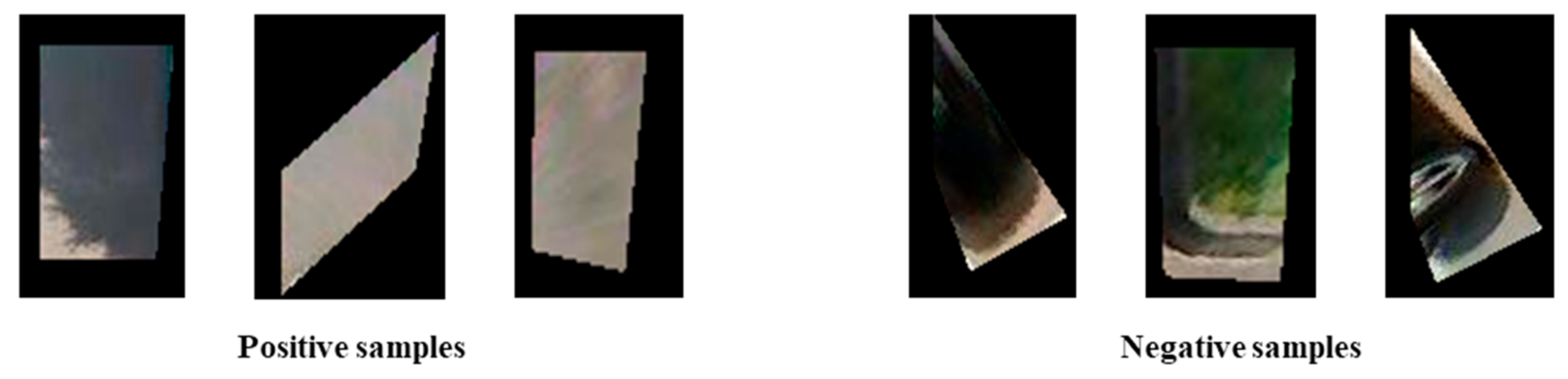
3.5. Vacant Parking Slot Classification

Among the detected parking slots, vacant parking slots are classified using an SVM [20]. We use a Lab color histogram as a feature for SVM classification. To obtain the feature, a region of interest (ROI) is set for each parking slot according to the shape of the parking slot. Then, the Lab color histogram is extracted from the ROI. In this study, the training dataset is manually collected, and some sample images in the dataset are shown in Figure 13.

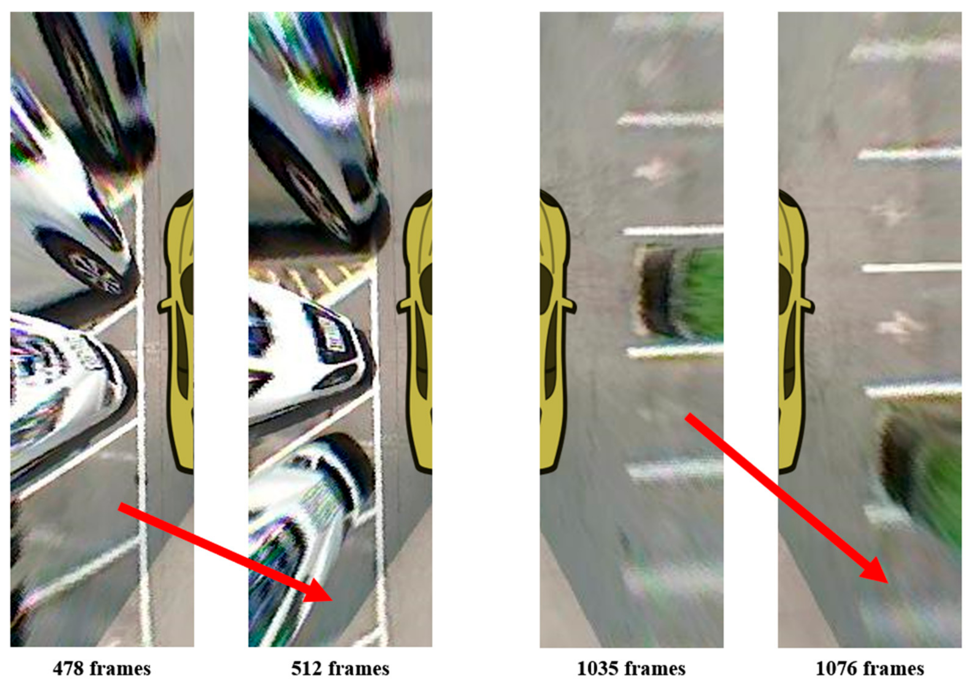
3.6. Multiple Parking Slot Tracking

In the process of generating an AVM image, an object having a certain height from the ground is distorted in the direction of the camera’s principal point [10]. Owing to this distortion, a vacant parking slot can be occluded by vehicles parked around them. This may cause a false detection that a vacant parking slot is recognized as an occupied parking slot. In addition, the resolution becomes degraded toward the edge of the AVM image due to the lack of spatial information to generate this region from a raw image, inducing unreliable detection result. Figure 14 shows the cases where the vacant parking slot is occluded by the parked vehicle and the parking line become blurred as it is getting far from the vehicle.
To solve this problem, the proposed method applies a tracking algorithm using the detection results in the previous frame. We modified the tracking algorithm introduced by Ra et al. [21]. Since parking slots present at the edge of the AVM image are severely blurred and occluded, the reliability of the detection result is low. Therefore, the AVM image is divided into two regions: (1) parking slot detection and tracking region denoted by R D & T and (2) parking slot tracking region denoted by R T . The tracking algorithm operates differently for each region, as depicted in Figure 15.
Let t r a c k t p denote the detected p th parking slot at time t . t r a c k t p contains the confidence value and Kalman filter [22] tracking information. The confidence value represents the reliability of the tracked parking slot, and it increases when the parking slot is successfully detected in two or more consecutive frames. If the confidence value decreases below a certain threshold value, the detection result is considered as unreliable. Then, the slot information will no longer be tracked. As a tracker, we used Kalman filter with constant-velocity model. The flowchart of proposed tracking process is described in Figure 16.

3.7. Parking Slot Detection Implemental Details

In this section, we describe two details about improving the parking slot detection accuracy. First, the location of F u J is refined to precisely determine P u J and θ u J . When calculating the location of the cross point using two line candidates, the calculated location may not exist on the actual intersection of the two line candidates due to AVM distortion. To fill this gap, we set an ROI around the P u J and update the F u J by calculating its location again in the ROI. The correction process is illustrated in Figure 17.
Second, to calculate F u J more effectively in a complex parking slot junction where three or more parking slot lines meet, we merge cross points having similar locations into a single cross point to reduce redundancy. The merging process is illustrated in Figure 18.

4. Experimental Results
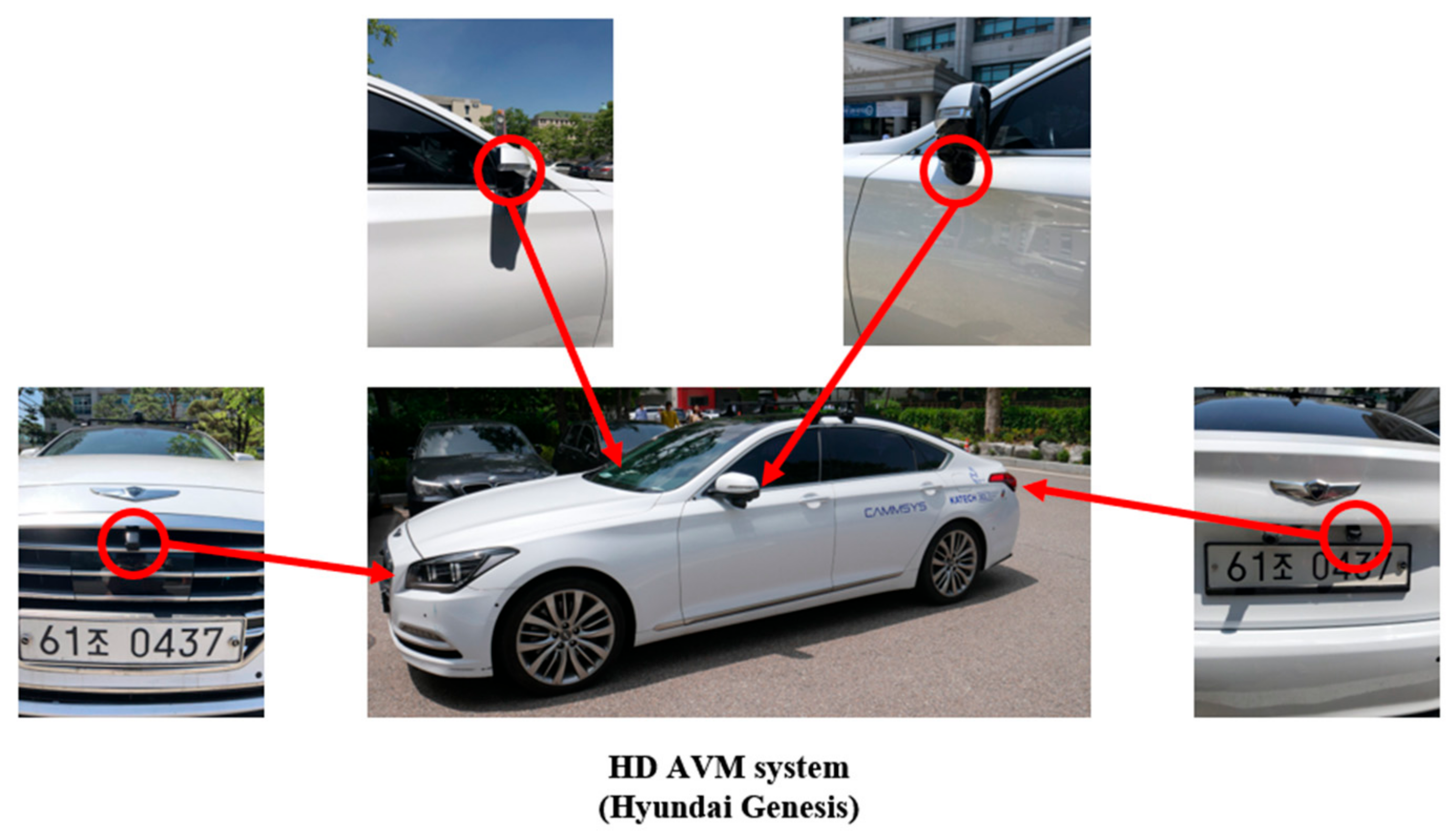
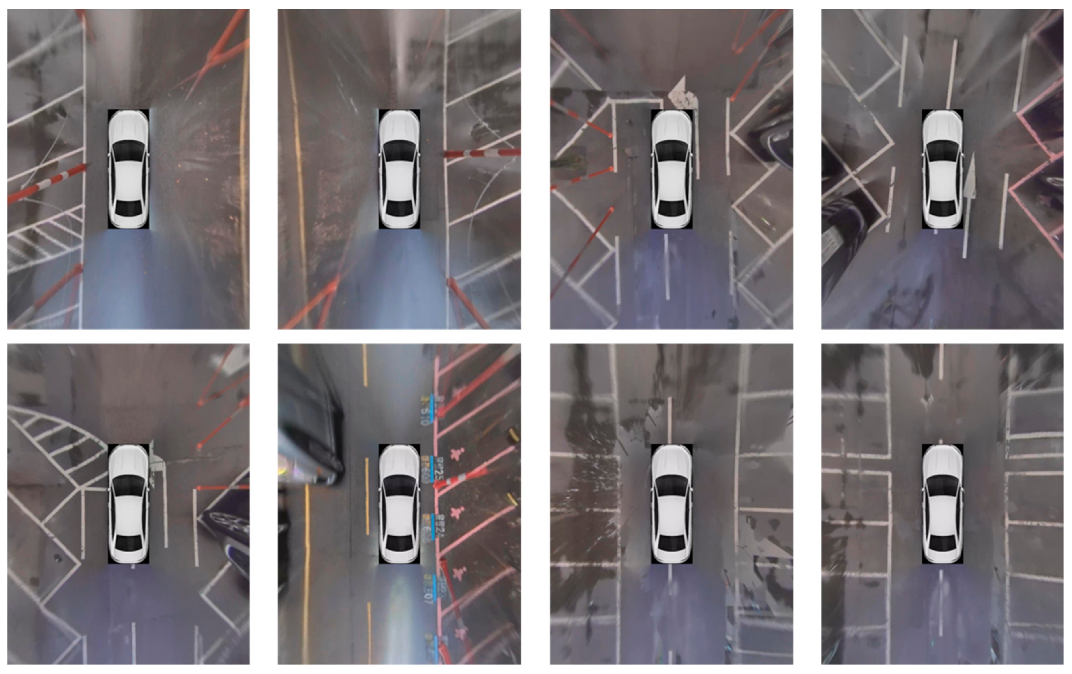
4.1. AVM Database

The performance of the proposed method is evaluated using the AVM dataset that was recorded with a Cammsys AVM system installed at Hyundai Genesis. The AVM system is shown in Figure 19, and the description of the dataset is shown in Table 2. To avoid data duplication, test data for quantitative evaluation consists of frames subsampled every 25 frames (about 1 s) from the original frames. Our dataset contains various types of parking slots and their variations, for example, rectangle, open, diamond, and slanted types as shown in Figure 20, Figure 21, Figure 22.

4.2. Parking Slot Detection Performance Evaluation

In this section, we evaluated performance of the proposed parking slot detection method by using precision and recall:
p r e c i s i o n = #   o f   c o r r e c t l y   c l a s s i f i e d   v a c a n t   p a r k i n g   s l o t s #   o f   d e t e c t e d   p a r k i n g   s l o t s
r e c a l l = #   o f   c o r r e c t l y   c l a s s i f i e d   v a c a n t   p a r k i n g   s l o t s #   o f   v a c a n t   p a r k i n g   s l o t s .
In addition, PS distance error is defined and calculated as a distance between the center locations of the detected parking slot and corresponding ground truth. Table 3, Table 4, Table 5 show the parking slot detection performance for each parking scenario. Due to the blur and distortion at the edge of the AVM image, the detection performance is only evaluated in a certain region as shown in Figure 23.
Table 3 shows the parking slot detection performance in the sunny scenario. The average precision, recall, and PS distance error are 97.41%, 97.34%, and 3.14 cm, respectively. The detection results in the sunny scenario are shown in Figure 24.
The detection results (marked ‘A’) as shown in Figure 24 show that the proposed method can successfully track the vacant parking slot even if it is occluded by parked vehicles nearby. Additionally, it can reconstruct the shape of parking slot entrances which consist of unusual shaped junction as shown in ‘B’ of Figure 24. The average distance errors of the scene 01 and scene 02 were relatively high and the recall of the scene 02 was significantly low compared to other scenes. By analyzing the detection results, we found the cause of such degradations. The failure cases are depicted in Figure 25.
The locational accuracy of the detected parking slot decreases at the edge of the AVM image because of the double vision as shown in ‘A’ of Figure 25. This effect occurs when positions of the mounted cameras are changed from their initial locations. In the scene 02 of Figure 25, there is water puddle (marked ‘B’) inside of the parking slot. Since the water reflects objects around the puddle, SVM failed to correctly classify vacancies of such parking slots.
Table 4 shows the parking slot detection performance in the cloudy scenario. The average precision, recall, and PS distance errors are 95.29%, 92.41%, and 3.47 cm. The detection results in the cloudy scenario are shown in Figure 26.
Figure 26 shows detection results for hard samples difficult to recognize parking slots due to the partial occlusion and modified shape of the junction. In Figure 26, additional markings meet at the junction of the slanted parking slot (marked ‘A’). Consequently, the shape of the junction becomes more complex than the typical one. However, the proposed method successfully recognizes such difficult case using the free junction type feature. In addition, even in the presence of an obstacle on the frontal guide line, it accurately detects the occluded parking slot as shown in ‘B’ of Figure 26B. Comparing ‘C’ and ‘D’ in Figure 26, the angles of two slanted lines are slightly different. Although these two slots are same type, existing methods using predefined slot information may fail to cover both cases; it is difficult to include all the variations in fixed templates or predefined settings. However, the proposed method can detect such parking slots with different angles because it adaptively combines junctions according to their directional similarity and geometric constraints. Figure 27 shows the failure cases in the cloudy scenario. In Figure 27, when the parking slot junction is occluded by an obstacle or water (marked ‘A’), the direction of each line segment is not correctly acquired in the process of analyzing θ u J . In addition, ‘B’ and ‘C’ in Figure 27 show the case that the locational accuracy decreases at the edge of the AVM image. This is because of the double vision effect, described in the previous results in the sunny scenario.
Table 5 shows the detection performance in the rainy scenario. The average precision, recall, and PS distance error are 97.76%, 88.98%, and 2.48 cm. The detection in the cloudy scenario are shown in Figure 28. It shows that the proposed method can detect open type parking slots which have different characteristics from other slot types. Since the open type parking slot has no frontal guide line, its junction is located at the end point of each parking line segment.
In the rainy scenario, the locational accuracy of detected parking slots is relatively higher than the others. This is because the wet asphalt enhances the contrast between the slot markings and background; the parking slot line is more clearly visible.
Most false detections in the rainy scenario occur due to the wet surface. The surface covered with water is highly reflective; thus, it creates sharp reflections of surrounding objects. Two main failure cases by the reflection are shown in Figure 29. In Figure 29, the reflection is displayed as white slot markings connected to the parking slot junction (marked ‘A’). This effect hinders the correct structure estimation of the junction. In addition, SVM misclassifies a vacant parking slot as an occupied one because the reflection creates long and sharp edges as shown in ‘B’ of Figure 29.

4.3. Comparative Experiment

We compared our method with Li et al. [16], which uses machine learning to detect junctions of the parking slots. Unlike our method, the method of Li et al. [16] has no further step to classify vacant parking slots from detected parking slots. Therefore, for the fair comparison, we discard detection results for occupied parking slots generated by the method of Li et al. [16].
The results of the quantitative evaluation for both methods are summarized in Table 6. For rectangular parking slots, both methods successfully detect most parking slots. Specifically, Li et al.’s method [16] shows better performance than our method for that type; the precision and recall are higher in most scenes. Although, there is an advantage of precision due to the exclusion of the occupied parking slots, its superiority is obvious and the results indicate that the detector trained by AdaBoost fully understands the structural characteristic of the typical junction shape of the rectangular parking slot. However, their method has a weakness that it cannot recognize parking slots having different types from the trained types, as shown in Figure 30. To handle more types, it also needs more data for various types and more sophisticated classifier to resolve ambiguity as the number of classes increases. Based on this analysis, our approach has an advantage in handling various types of parking slots. The proposed method does not focus on the type, but finds possible combinations of junctions according to the geometric constraints such as directional similarity, distance, and pose. Consequently, although our method shows relatively low performance than the machine learning based approach for a certain slot type, it can detect various shaped parking slots with reasonable precision and recall regardless of their types.

5. Conclusions

We have developed a parking slot detection method by using free junction type features to detect the various types of parking slots without predefined parking slot information. To generate free junction type features, each junction location is acquired by calculating cross points of multiple parking slot lines and end points of a single parking slot line. Then, line directions around each junction location are analyzed to obtain structural information of the junction and embedded to the free junction type features. By combining the free junction type features, according to the geometric constraints of the parking slot, the proposed method can detect various types of parking slots without predefined parking slot information. Finally, the vacancy of the detected parking slot is recognized by the SVM classifier using the Lab color histogram as a feature. To enhance the detection performance in sequential frames, the Kalman tracker with constant velocity model is applied for each detected vacant parking slot. Since the reliability of the detection results is degraded at the edge of the AVM image, the AVM image is divided into two regions where detection and prediction are performed in one region and only prediction is performed in another region. The performance of the proposed method was evaluated in various parking environments, including weather changes and modified parking slot types. Although our method showed slightly lower performance than a machine learning based approach for a certain slot type, it could successfully detect other types of parking slots which cannot be detected by the machine learning based approach. In addition, our method achieved very stable performance in the field test with vehicle control. However, there are several exceptional situations, which need the driver’s intervention, such as snow conditions, pedestrians crossing the road, and encountering a driving vehicle. Those extreme conditions must be addressed to achieve a fully autonomous intelligent PAS. For our future work, we are trying to apply a sensor fusion approach utilizing ultrasonic sensor mounted on a vehicle to overcome such hurdles.

Author Contributions

Data curation, S.K. and J.K.; Investigation, S.K.; Methodology, J.K.; Project administration, M.R.; Supervision, W.-Y.K.; Validation, J.K.; Writing—Original draft, S.K.; Writing—Review and editing, M.R. and W.-Y.K. All authors have read and agreed to the published version of the manuscript.

Funding

This work was supported by Korea Evaluation Institute of Industrial Technology (KEIT) grant funded by the Korea government (MOTIE) (No.20000293, Road Surface Condition Detection using Environmental and In-vehicle Sensors).

Conflicts of Interest

The authors declare no conflict of interest.

References

  1. Wikipedia Contributors. Intelligent Parking Assist System—Wikipedia, The Free Encyclopedia. 2020. Available online: https://en.wikipedia.org/wiki/Intelligent_Parking_Assist_System (accessed on 10 October 2020).
  2. Nardo, M.D.; Forino, D.; Murino, T. The evolution of man–machine interaction: The role of human in Industry 4.0 paradigm. Prod. Manuf. Res. 2020, 8, 20–34. [Google Scholar] [CrossRef] [Green Version]
  3. Tanaka, Y.; Saiki, M.; Katoh, M.; Endo, T. Development of image recognition for a parking assist system. In Proceedings of the 13th World Congress on Intelligent Transport Systems and Services, London, UK, 8–12 October 2006; pp. 1–7. [Google Scholar]
  4. Lee, S.; Hyeon, D.; Park, G.; Baek, I.J.; Kim, S.W.; Seo, S.W. Directional-DBSCAN: Parking-slot detection using a clustering method in around-view monitoring system. In Proceedings of the 2016 IEEE Intelligent Vehicles Symposium (IV), Gothenburg, Sweden, 19–22 June 2016; pp. 349–354. [Google Scholar]
  5. Du, X.; Tan, K.K. Autonomous reverse parking system based on robust path generation and improved sliding mode control. IEEE Trans. Intell. Transp. Syst. 2014, 16, 1225–1237. [Google Scholar] [CrossRef]
  6. Lee, S.; Seo, S.W. Available parking slot recognition based on slot context analysis. IET Intell. Transp. Syst. 2016, 10, 594–604. [Google Scholar] [CrossRef]
  7. Wang, C.; Zhang, H.; Yang, M.; Wang, X.; Ye, L.; Guo, C. Automatic parking based on a bird’s eye view vision system. Adv. Mech. Eng. 2014. [Google Scholar] [CrossRef]
  8. Houben, S.; Komar, M.; Hohm, A.; Lüke, S.; Neuhausen, M.; Schlipsing, M. On-vehicle video-based parking lot recognition with fisheye optics. In Proceedings of the 16th International IEEE Conference on Intelligent Transportation Systems (ITSC 2013), The Hague, The Netherlands, 6–9 October 2013; IEEE: Piscataway, NJ, USA, 2013; pp. 7–12. [Google Scholar]
  9. Allodi, M.; Castangia, L.; Cionini, A.; Valenti, F. Monocular parking slots and obstacles detection and tracking. In Proceedings of the 2016 IEEE Intelligent Vehicles Symposium (IV), Gothenburg, Sweden, 19–22 June 2016; pp. 179–185. [Google Scholar]
  10. Suhr, J.K.; Jung, H.G. Automatic Parking Space Detection and Tracking for Underground and Indoor Environments. IEEE Trans. Ind. Electron. 2016, 63, 5687–5698. [Google Scholar] [CrossRef]
  11. Suhr, J.K.; Jung, H.G. A universal vacant parking slot recognition system using sensors mounted on off-the-shelf vehicles. Sensors 2018, 18, 1213. [Google Scholar] [CrossRef] [PubMed] [Green Version]
  12. Hamada, K.; Hu, Z.; Fan, M.; Chen, H. Surround view based parking lot detection and tracking. In Proceedings of the 2015 IEEE Intelligent Vehicles Symposium (IV), Seoul, Korea, 28 June–1 July 2015; IEEE: Piscataway, NJ, USA, 2015; pp. 1106–1111. [Google Scholar]
  13. Jung, H.G.; Kim, D.S.; Yoon, P.J.; Kim, J. Parking Slot Markings Recognition for Automatic Parking Assist System. In Proceedings of the 2006 IEEE Intelligent Vehicles Symposium, Tokyo, Japan, 13–15 June 2006. [Google Scholar]
  14. Jung, H.G.; Lee, Y.H.; Kim, J. Uniform user interface for semiautomatic parking slot marking recognition. IEEE Trans. Veh. Technol. 2009, 59, 616–626. [Google Scholar] [CrossRef]
  15. Suhr, J.K.; Jung, H.G. Full-automatic recognition of various parking slot markings using a hierarchical tree structure. Opt. Eng. 2013, 52, 037203. [Google Scholar] [CrossRef]
  16. Li, L.; Zhang, L.; Li, X.; Liu, X.; Shen, Y.; Xiong, L. Vision-based parking-slot detection: A benchmark and a learning-based approach. In Proceedings of the 2017 IEEE International Conference on Multimedia and Expo (ICME), Hong Kong, China, 10–14 July 2017; IEEE: Piscataway, NJ, USA, 2017; pp. 649–654. [Google Scholar]
  17. Fan, M.; Hu, Z.; Hamada, K.; Chen, H. Line Filter-Based Parking Slot Detection for Intelligent Parking Assistance System. In Proceedings of the SAE-China Congress 2014: Selected Papers; Springer: Berlin/Heidelberg, Germany, 2015; pp. 175–181. [Google Scholar]
  18. Radon, J. On the determination of functions from their integral values along certain manifolds. IEEE Trans. Med. Imaging 1986, 5, 170–176. [Google Scholar] [CrossRef] [PubMed]
  19. Kong, T.Y.; Rosenfeld, A. Topological Algorithms for Digital Image Processing; Elsevier: Amsterdam, The Netherlands, 1996. [Google Scholar]
  20. Cortes, C.; Vapnik, V. Support-vector networks. Mach. Learn. 1995, 20, 273–297. [Google Scholar] [CrossRef]
  21. Ra, M.; Jung, H.G.; Suhr, J.K.; Kim, W.Y. Part-based vehicle detection in side-rectilinear images for blind-spot detection. Expert Syst. Appl. 2018, 101, 116–128. [Google Scholar] [CrossRef]
  22. Welch, G.; Bishop, G. An Introduction to the Kalman Filter; University of North Carolina at Chapel Hill: Chapel Hill, NC, USA, 2001. [Google Scholar]
Figure 1. Predefined junction and parking slot generation results with the combination of multiple junctions.
Symmetry 12 01725 g001
Figure 2. Examples of the detection of modified parking slots using free junction type features.
Symmetry 12 01725 g002
Figure 3. Pictorial depiction of the terminologies used in the proposed parking space detection method.
Symmetry 12 01725 g003
Figure 4. The proposed parking slot detection method. AVM: around-view monitoring.
Symmetry 12 01725 g004
Figure 5. Line response extraction results.
Symmetry 12 01725 g005
Figure 6. Comparison of the Radon transform and the proposed normalized Radon transform: (a) Line response map; (b) Radon transform result; (c) normalized Radon transform result (Pseudo color map/3D mesh map).
Symmetry 12 01725 g006
Figure 7. Parking line candidate detection results.
Symmetry 12 01725 g007
Figure 8. Cross points detection results.
Symmetry 12 01725 g008
Figure 9. End points detection results.
Symmetry 12 01725 g009
Figure 10. Process of line direction analysis for free junction type feature.
Symmetry 12 01725 g010
Figure 11. Free junction type feature extraction results.
Symmetry 12 01725 g011
Figure 12. Parking slot entrance detection results.
Symmetry 12 01725 g012
Figure 13. Training samples of vacant parking slot classifier.
Symmetry 12 01725 g013
Figure 14. Examples of parking slot occlusion and parking line blur.
Symmetry 12 01725 g014
Figure 15. Illustration of the two separated regions. The detection and tracking are performed in the violet region, and only tracking is performed in the green region.
Symmetry 12 01725 g015
Figure 16. Flowchart of the proposed multiple parking slot tracking process.
Symmetry 12 01725 g016
Figure 17. Correction process of the parking slot line cross point.
Symmetry 12 01725 g017
Figure 18. Merging process for the complex parking slot junction.
Symmetry 12 01725 g018
Figure 19. Camera configuration of the AVM system. HD: high definition.
Symmetry 12 01725 g019
Figure 20. AVM dataset samples (sunny scenario). The dataset contains parking slots for people with disabilities, women-only rectangular parking slots, diamond parking slots with extra slot markings, and parking slots having different pose and type.
Symmetry 12 01725 g020
Figure 21. AVM dataset sample (cloudy scenario). The dataset is captured in poor lighting environment. It contains contaminated slot markings, diamond and slanted parking slots with different segment line angles, parking slots partially occluded by road pole, and water puddle on parking slots.
Symmetry 12 01725 g021
Figure 22. AVM dataset sample (rainy scenario). The dataset is captured in wet conditions where reflection is occurred by surface covered with water. It contained open type parking slots, and rectangular parking slots for compact cars.
Symmetry 12 01725 g022
Figure 23. The region where the detection performance is evaluated. The detection results in the blue region are used to calculate the detection performance. The detection results in the red region are discarded.
Symmetry 12 01725 g023
Figure 24. Parking slot detection results (sunny scenario).
Symmetry 12 01725 g024
Figure 25. Failure in the detection of the parking slot (sunny scenario).
Symmetry 12 01725 g025
Figure 26. Parking slot detection results (cloudy scenario).
Symmetry 12 01725 g026
Figure 27. Failure of the parking slot detection (cloudy scenario).
Symmetry 12 01725 g027
Figure 28. Parking slot detection results (rainy scenario).
Symmetry 12 01725 g028
Figure 29. Failure of the parking slot detection (rainy scenario).
Symmetry 12 01725 g029
Figure 30. Misclassification for diamond type parking slot in Li et al. [16]. Yellow solid lines are a prediction result. Red solid lines represent the entrance of each parking slot.
Symmetry 12 01725 g030
Table 1. Characteristics of the two types of slot junctions.
Cross Point of Parking Slot LineEnd Point of Parking Slot Line
Is there a frontal guide line? YesNo
Is there a line segment?YesYes
Junction locationCross location between the frontal guide line and line segmentEnd location of the line segment
Examples Symmetry 12 01725 i001 Symmetry 12 01725 i002
Table 2. Description of the test dataset.
ScenariosNumber of FramesNumber of Frames Used for Test
SunnyScene 1115547
Scene 2135556
Scene 3195580
Scene 4150561
Scene 5108044
Scene 6175571
Scene 7210585
Scene 8210585
Scene 93905157
Scene 103755151
Scene 11150561
Scene 12195579
Scene 132705109
CloudyScene 1230593
Scene 22505103
Scene 398040
Scene 4240597
Scene 5210585
Scene 6235595
Scene 7210585
Scene 84610191
RainyScene 1200582
Scene 2195579
Total50,1702036
Table 3. Parking slot (PS) detection performance (sunny scenario).
DatasetNumber of Vacant Parking SlotsNumber of Detected Parking SlotsNumber of Correctly Classified Parking SlotsPrecision
(%)
Recall
(%)
PS Distance Error (cm)
Scene 0162616098.3696.777.48
Scene 0253434195.3577.367.48
Scene 0314314213997.8997.202.65
Scene 041001009999.0099.001.34
Scene 05777676100.0098.703.02
Scene 0610210310198.0699.022.55
Scene 0714014013797.8697.862.57
Scene 0872706998.5795.832.60
Scene 0925624624499.1995.312.38
Scene 1025027025092.59100.001.38
Scene 1188898797.7598.862.23
Scene 1272737298.63100.001.85
Scene 1389908998.89100.003.27
TOTAL15041503146497.4197.343.14
Table 4. Parking slot detection performance (cloudy scenario).
DatasetNumber of Vacant Parking SlotsNumber of Detected Parking SlotsNumber of Correctly Classified Parking SlotsPrecision
(%)
Recall
(%)
PS Distance Error (cm)
Scene 0113712912395.3589.783.14
Scene 0214814914194.6395.272.67
Scene 0356575698.25100.003.47
Scene 0417618417293.4897.733.41
Scene 0514314113696.4595.103.38
Scene 0615513713497.8186.452.68
Scene 0715315914389.9493.465.11
Scene 0825823322897.8588.373.87
TOTAL12261189113395.2992.413.47
Table 5. Parking slot detection performance (rainy scenario).
DatasetNumber of Vacant Parking SlotsNumber of Detected Parking SlotsNumber of Correctly Classified Parking SlotsPrecision
(%)
Recall
(%)
PS Distance Error (cm)
Scene 0181727198.6187.652.44
Scene 0216415114797.3589.632.51
TOTAL24522321897.7688.982.48
Table 6. Performance comparison between proposed method and existing method.
ScenariosProposedLi et al. [16]
Precision
(%)
Recall
(%)
Precision
(%)
Recall
(%)
DaylightScene 198.3696.7700
Scene 295.3577.3600
Scene 397.8997.2000
Scene 499.0099.0000
Scene 5100.0098.7000
Scene 698.0699.02100.00100.00
Scene 797.8697.86100.00100.00
Scene 898.5795.8399.0198.57
Scene 999.1995.31100100
Scene 1092.59100.0000
Scene 1197.7598.86100.0098.25
Scene 1298.63100.00100.00100.00
Scene 1398.89100.0000
CloudyScene 195.3589.7800
Scene 294.6395.2700
Scene 398.25100.0000
Scene 493.4897.73100.0097.11
Scene 596.4595.10100.0097.06
Scene 697.8186.45100.0095.33
Scene 789.9493.4697.0189.04
Scene 897.8588.3700
RainScene 198.6187.6500
Scene 297.3589.63100.0098.77
Publisher’s Note: MDPI stays neutral with regard to jurisdictional claims in published maps and institutional affiliations.

