Abstract
The energy limitation remains one of the biggest constraints in drone path planning, since it prevents drones from performing long surveillance missions. To assist drones in such missions, recharging stations have recently been introduced. They are platforms where the drone can autonomously land to recharge its battery before continuing the mission. However, the cost of those platforms remains a significant obstacle to their adoption. Consequently, it is important to reduce their number while planning the path of the drone. This work introduces the Single Drone Multiple Recharging Stations on Large Farm problem (SD-MRS-LF). A large farm is considered as an area of interest to cover with a set of candidate locations where recharging stations can be installed. The aim is to determine the path of the drone that minimizes the number of locations for recharging stations as well as the completion time of the surveillance mission. This path planning problem falls within the realm of computational geometry and is related to similar problems that are encountered in the field of robotics. The problem is complicated due to environmental constraints on farms such as wind speed and direction, which produce asymmetries in the optimal solution. A back-and-forth-k-opt simulated annealing (BFKSA) approach is proposed to solve the defined problem. The new approach is compared to the basic back-and-forth (BF) and a K-opt variant of the well-known simulated annealing (KSA) approach over a set of 20 random topologies in different environmental conditions. The results from computational experiments show that the BFKSA approach outperforms the others, in terms of providing feasible solutions and minimizing the number of recharges.
1. Introduction
One of the latest developments in agriculture is the use of drones. According to a recent PwC report [1], the agricultural drone market is estimated at USD 32.4 billion, taking the second largest share of the market. In, particular, drones are increasingly used in the surveillance of farms [2]. In this application, drones fly over an area of interest to take pictures that can be analyzed later for different purposes including crop yield estimation, early warning of pests and disease, disaster risk reduction, and so on. Drone can be operated in two modes: manual mode requiring a remote human intervention and automatic mode in which the path of drone is determined beforehand [3]. This last mode requires prior planning of the drone path, commonly known as coverage path planning (CPP) [4]. More precisely, CPP for drones may be defined as the determination of an optimal path allowing a drone to complete a coverage mission, while minimizing the mission’s completion time. The area of interest in agriculture is typically a farm that may be represented as a sequence of vertices that form a planar polygon. This polygon generally is decomposed into smaller cells to facilitate the coverage task. The decomposition is essentially based on the ground sampling distance (GSD), which represents the distance between pixel centers measured on the ground [5].
The major constraint in drone CPP is the small capacity of the drone’s battery, which limits the drone’s available energy and thus its flight range. For this reason, much research in the area of CPP has been focused on the development of energy-aware algorithms. One of the main ideas behind common algorithms is the assumption that a drone spends a lot of time and energy making turns [6,7]. Thus, those algorithms modify conventional trajectories such as back-and-forth [8] and HILBERT [9]. An interesting survey on coverage path planning with drones can be found in [10].
Regardless of the efficiency of algorithms, large-scale surveillance missions will require more than a single trip. For instance, the authors in [11] conducted around 200 flights to survey an area of about 29.5 ha with a battery-powered DJI Inspire 1 quadcopter. In an area of four square kilometers as it is the case in [12], a DJI Phantom 3 Professional drone requires at least 10 flights for a mission. Consequently, recharging stations have recently been introduced to assist the drone in continuous operation [13,14]. When the drone runs out of energy, it may land on a recharging station to recharge its battery. Even if it is possible for a drone to land on a moving platform [15] and perform a dynamic wireless charging [16], the movement of such a platform in many farms is limited due the lack of proper roads throughout the farm. Most of the current literature considers predefined locations for recharging stations. For example, authors in [17] use only one drone with some recharging stations located at predefined sites. They tried to minimize the mission completion time by deciding when the drone should stop for charging depending on the state of charge (SoC). Reference [18] takes an alternative approach, by considering a fleet of drones with only one recharging station located at the center of the area of interest—the aim is to cover the area of interest with a constraint on energy replenishment scheduling. Since only one recharging station is used, the surveyed area is limited to a radius of half the traveling distance of a drone, so that the drone can make a round trip to the recharging station.
To automatically survey a larger area will require at least one recharging station located at an acceptable position. The first attempt to solve this issue of determining the optimal location of recharging stations is found in [19]. Authors proposed a Drone Delivery Recharging Location Model (DDRLM) that optimizes the location of a set of recharging stations with the aim of maximizing the customer demand that can be served. In this formulation, the number of recharging stations is given beforehand.
Besides finding optimal locations for recharging stations, their number should also be minimized to reduce the cost of the overall architecture. Actually, the cost of an additional recharging station can significantly influence the cost of the overall architecture. For example, the Heisha recharging station costs about 1000 USD, while a Mavic Air drone that can be recharged using this station costs barely half the price (600 USD) [20]. This shows the necessity to reduce the number of recharging stations, especially for users with limited budgets such as low-income users.
This work introduces the Single Drone Multiple Recharging Stations in Large Farm problem (SD-MRS-LF). Unlike the work in [19] which focuses on the determination of the locations for a given number of recharging stations, this work rather tackles drone path planning with a priority on the economical point of view. In this formulation, an area of interest is given as well as a set of candidate locations within the area of interest where recharging stations may potentially be installed. The objective is two-fold: first to minimize the number of actually used recharging stations and secondly to minimize the completion time of the surveillance mission. The solution with the smallest number of recharging stations will be the best regardless the completion time, since the priority is to reduce the cost. In case more than one solution provide the smallest number of recharging stations, the one with the smallest completion time will be considered as the best. To solve this problem, a new approach has been proposed: back-and-forth-k-opt simulated annealing (BFKSA). BFKSA is a combination of the two well-known algorithms, back and forth (BF) and the K-opt variant of simulated annealing (SA). The idea behind BFKSA is based on the assumption that the quality of the initial solution provided to a SA algorithm can influence the final solution.
The rest of the paper is organized as follows: Section 2 presents the system modelling and the formulation of the Single Drone Multiple Recharging Stations in Large Farm problem. Section 3 presents and explains the Back-and-Forth-k-opt Simulated Annealing approach defined to solve the problem. Section 4 presents the simulation setup and compares the results with basic Back-and-Forth and Simulated Annealing approaches. This paper ends with a conclusion and a look at future work.
2. System Modelling and Problem Formulation
2.1. Basic Assumptions
The following realistic assumptions and approximations have been made to specify the problem:
- The drone begins the mission fully charged, but a single charge does not supply enough energy for the entire mission.
- The flying status of the drone is one of two possibilities: vertical moving (take-off/landing), or horizontal motion [21].
- Take-off energy and landing energy is negligible compared to the energy required for flight.
- The drone flies at a constant altitude throughout the mission (except when recharging).
- The area to cover presents no obstacles to impede the drone’s flight. In practice, drones may fly at altitudes at 120 m which is higher than the tallest trees.
- Weather conditions (including temperature, air pressure, relative humidity, and wind speed) are constant over the entire region, during the entire mission. Note that weather conditions such as wind and temperature can affect the energy consumption. The ambient temperature may influence the battery drain and capacity [22] while the wind may affect either positively or negatively the forward movement of the drone [23], depending on the wind speed and direction, as well as the flying status of the drone.
- Recharging stations are located within the area to enable the drone to complete its mission. There are a number of pre-identified candidate locations within the region where charging stations may potentially be located.
- The drone can only visit a recharging station once per mission. This assumption reflects the fact that once a recharge is performed, the station will require a period of time to recharge itself (possibly using solar energy).
2.2. Scenario Modeling
Farm areas typically can be described as planar polygons. Unlike urban areas that may contain nonflying zones or tall buildings, the aerial space over a farm is generally free of obstacles. In this scenario, an area to cover is considered as a rectangular form of size m2 and decomposed into cells as illustrated in Figure 1a. The set of the cells is represented by and contains elements among which some cells are candidate locations where recharging stations may conveniently be deployed. The set of candidate locations is represented by , with .
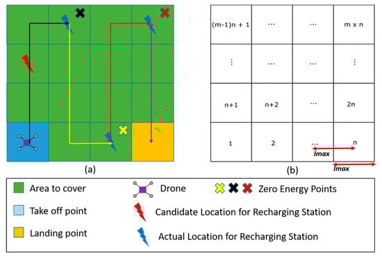
Figure 1.
Description of the area of interest: (a) area to cover with candidate location for recharging stations; (b) numbering of the decomposed cells.
The decomposition of our target area into a grid depends on the maximum image collection distance interval of the drone. This distance interval depends on the specification of the drone (the field of view angle and the resolution of the camera) and the overlap requirement during image collection. The maximal value of the distance separating image collection points (as shown in Figure 1b) is computed using (1) as proposed in [24].
is the opening angle of the camera; H is the drone’s altitude, and the overlap ratio.
Figure 2 shows the geometry used to derive (1), with I the size of a cell of the grid.
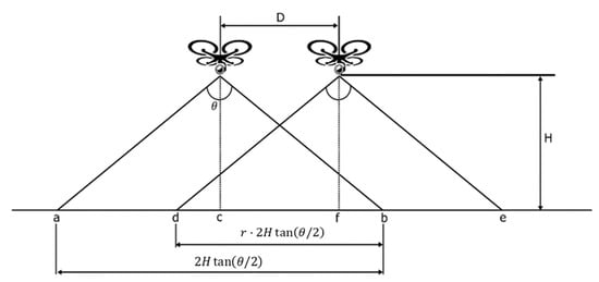
Figure 2.
Consecutive positions of drone’s camera.
In real scenarios in farm surveillance, the minimal resolution of each collected image is an important aspect for image processing in further stages. This minimal resolution depends on the purpose of the surveillance mission. Given an image resolution , the spatial resolution obtained by taking a picture at an altitude with a field of view angle can be computed by Equation (2).
If we consider the minimal resolution required by the mission, we obtain the inequality
From (3) we deduce the maximum altitude the drone can fly.
The maximum altitude with respect to the image resolution requirement is generally used to minimize the time of the mission. During the remote sensing mission for monitoring sorghum growth, the authors in [25] used a ReadyMadeRC Anaconda drone equipped with a camera of 1.2 megapixels and flying at an altitude of 120 m which provided a spatial resolution of approximately 6.5 cm. In addition, the maximum altitude of the drone can be legally restricted.
Due to budget limitation only one drone is considered with a maximal capacity energy . Each time the drone stops at a recharging station, it recharges its battery to before leaving. The mission starts at a given take-off point and ends at a given landing point that maybe different from the take-off point.
2.3. Energy Consumption Model
Under horizontal motion, drones power expenditure may be broken into two components: one component for lift, and the second to overcome the parasitic drag that hinders its forward movement in free space [26,27]. The total power in horizontal moving is given by (5). Details on how the formula is derived are presented in [28].
with
where
- is the required total power (in );
- is the required power to overcome the parasitic drag (in );
- is the required power to lift the drone (in );
- is the aerodynamic drag coefficient;
- is the front facing area (in );
- is the total weight of the drone (in );
- is the density of the air (in );
- is the width of the drone (in );
- is the speed of the drone relative to the wind (in m/s).
Since and are respectively proportional and inversely proportional to the speed of the drone, a tradeoff (optimum speed) that minimizes the power consumption of the drone during horizontal moving should therefore be found. To compute this optimum speed, we use (8) proposed by [28].
All the parameters are the same used in (6) and (7). Several energy models have been proposed in the literature. The energy consumed during horizontal flight has been considered approximately constant [23], but it is not true in real case scenarios. The authors in [17] tried to derive a more realistic energy model based on empirical experiments. However, the model is tailored for experimental conditions in which the study has been conducted. In this paper, we will consider Equation (8) to derive an energy model. The energy consumed during a time and a power is given by
The time can also be expressed as
where , , and representing respectively the distance traveled, drone speed relative to the wind, the wind speed, and the relative angle between the wind and the travel direction. Considering Equations (5)–(10), we may express energy consumption in terms of drone velocity relative to wind speed as
where and
Taking the derivative with respect to , we find the optimization condition for the optimal speed
In the case this gives an optimal velocity that is expressed in Equation (13),
Which agrees with (5). In the general case, we may write . This gives the optimum condition
Multiplying by and noting that we obtain Equation (15)
where This gives a 5th order Equation (16)
Denoting the largest root of Equations (16) by we obtain the expression of the optimal speed in Equation (17), where the parameter corresponds to the cruise speed.
The energy consumption is then given by Equation (18)
We use the specifications of the manufacturer to derive and . The specifications for the 3DR Solo drone are the following:
- Cruise speed = 2.5 m/s,
- Max flight time: 25 min.
- Energy: 5200 mAh, 14.8 VDC = 77 Wh = 277,200 W-s
From these numbers we may derive the power consumed at 2.5 m/s = 77 Wh/(25/60) = 185 Watts. From (5)–(7) we have
From the cruise speed, we may derive: which implies
Solving Equations (19) and (20) for gives
Finally, the energy consumption is estimated by plugging these parameters into (18)
where
and is the largest root of Equation (24)
2.4. Problem Formulation
The Single Drone Multiple Recharging Stations in Large Farm problem (SD-MRS-LF) is defined as follows: given an area of interest decomposed into a set of cells and a set of candidate locations for recharging station(s) , determine a route that minimizes the number of actually used recharging stations and the completion time of the mission. A route may be characterized as a permutation of the elements of . More specifically, with .
The objective functions are given by (25) and (26). They respectively minimize the number of recharging stations and the total traveling time.
with
- is the number of elements in ;
- ;
- is the distance between and ;
- is the optimal speed of the drone to move from point to point ;
- is the wind speed;
- is the relative angle between the wind and the travel direction;
- is the set of actually used recharging stations.
2.5. Complexity Analysis of the Problem
Let us consider the take-off point and the final landing node of the drone to be the same. The given problem can easily be reduced to the traveling salesman problem (TSP) by considering each cell to cover as a city to visit. Since each cell and recharging station can be visited once only, the problem amounts to find the best arrangement starting from the take-off point considered as the depot to the final landing point which is the same point. The given problem is therefore NP-hard with factorial time complexity .
For instance, an area of size contains 64 cells corresponding to arrangements. Evaluating such a number of arrangements using an exhaustive strategy would require years on a CPU with a clock speed of 4 gigahertz. That is why metaheuristics are good alternatives.
3. Back-and-Forth-k-opt Simulated Annealing Approach (BFKSA)
3.1. Background
BFKSA is a combination of three algorithms: back-and-forth, k-opt, and simulated annealing. In the following subsections, we describe these three algorithms. In Section 3.2. we will describe how the three algorithms are integrated together to construct the BFKSA algorithm.
3.1.1. Back-and-Forth (BF)
BF is the simple technique mainly used in regular areas. It is inspired by ‘the way of the ox’. In fact, when an ox trails a plow and has to cover an area, it moves in a straight line along the field, turns around, and then traces a new straight path adjacent to the previous one. BF is considered as an energy-aware algorithm since it reduces the number of turns made by a drone. For instance, in Figure 3a,b, the drone makes only six turns to cover the area of interest. A BF route can be generated using Algorithm 1 or Algorithm 2.
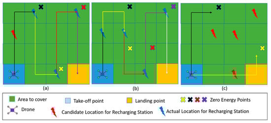
Figure 3.
Back-and-forth solutions on a 4 4 grid: (a) an instance with a BFv solution using 3 RS; (b) an instance with a BFv solution using 4 RS; (c) an instance with no feasible BF solution neither BFv (Black) nor BFh (Yellow).
A generated route may not be feasible. A route is feasible if the maximum energy of the battery allows the drone to fly from the starting point or an intermediary recharging station to the closest recharging station on the route; or from the last recharging station to the final landing point. Algorithm 3 minimizes the number of recharging stations as given by (24) on a given route when the route is feasible.
Depending on the location of the recharging stations, three cases can be observed (Figure 3):
In the last two cases, modifying the BF route may decrease the number or recharging stations or turn an infeasible route into a feasible one. This can be done by combining back-and-forth with metaheuristics such as simulated annealing, as described below.
3.1.2. Simulated Annealing (SA)
SA is inspired from the annealing process in metallurgy. The idea consists of generating an initial route and then performing several iterations to improve this route. A neighbor route is generated from the previous one at each iteration. The new route is accepted if it improves the value of the objective function. If it is not the case, the new route is accepted with a probability depending on the current temperature and the difference between the new and previous values of the objective function (denoted by ). The probability in the SA algorithm generally follows the Boltzmann distribution given by . Since the temperature updates each time the equilibrium state is reached, the probability of accepting non-improving routes decreases.
| Algorithm 1: Back and Forth Vertical (BFv) |
| Input: : Area to cover Output: : A route; |
 |
| Algorithm 2: Back and Forth Horizontal (BFh) |
| Input: : Area to cover Output: : A route; |
 |
| Algorithm 3: Recharging Station Minimization (RSM) |
| Input: : a route; : Set of Candidate RS Output: : set of actual RS |
 |
3.1.3. K-Opt Algorithm
The basic simulated annealing randomly selects a new solution in the neighborhood of the current solution . This selection process presents some limitations. First, the same neighbor solution can be evaluated several times since there is no mechanism to recognize already visited solutions. In some special cases, the algorithm can even be trapped in a local loop, switching between and . Secondly, by selecting only one solution in the neighborhood of , another neighbor solution better than can be ignored. To mitigate these limitations, a local search in the neighborhood of a current solution is usually performed.
One of the most widely used local search algorithms is the k-opt algorithm. It is a generalization of the 2-opt algorithm proposed by Georges Croes in 1958 to solve the traveling salesman problem. The algorithm is based on the k-opt operator and works as follows: at each step, k edges are removed from the current solution and the k partitions are therefore reconnected to form a new solution. An application of the 2-opt and the 3-opt operator on a given route R is illustrated in Figure 4.
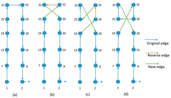
Figure 4.
Application of 2-opt and 3-opt operators on a partial instance of size 66. (a) initial route; (b) a neighbor route by deleting edges (25,31) and (32,26); (c) a neighbor route by deleting edges (19,25), (31,32), and (26,20); (d) a neighbor route by deleting edges (19,25), (31,32), and (26,20) without reversing remaining edges.
3.2. BFKSA Algorithm
The Back-and-Forth Simulated Annealing is given in Algorithm 4.
Initial Route (line 2): The initial route is obtained using Algorithm 5 (GenerateInitialRoute). BF algorithm can consider either vertical orientation (Figure 5b) or horizontal orientation (Figure 5c). The idea in Algorithm 5 is to run BF in both directions and to consider the orientation that provide the best value for and depending on wind direction. In case there is no feasible solution, the orientation that forms the smallest angle with the wind direction is taken. In this paper, we consider three directions for the wind: (0,1), (1,1), (1,0), shown in Figure 5a.
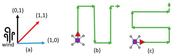
Figure 5.
Wind’s influence on the determination of the BF orientation. (a) Three wind’s directions are considered; (b) BF orientation for wind direction (0,1); (c) BF orientation for wind direction (1,0).
Fitness functions (lines 3 and 11): the two objective functions namely and are evaluated using respectively Equations (3) and (4). The number of actual recharging stations in a route is reduced using Algorithm 2 (recharging station minimization).
Generating a new route (line 8–10): the process of finding a new route starts by randomly selecting three indexes that will correspond to the edges to delete on the current route. Then, by using GenerateRoutes(), new solutions are derived from the current one using a k-opt operator that deletes k edges and builds a new route. The value of k varies between 2 and 3. For a given route R, all the routes derived by applying a 2-opt or 3-opt are tested and the best is kept. Since the proposed model considers the wind direction, a reverse edge may consume a different energy quantity compared to the original edge (Figure 4). The determination of the best local route is given in Algorithm 6.
Stopping condition (line 6): the algorithm stops when the current temperature is lower than the minimal temperature or after reaching several equilibrium stages without improvement. We suppose therefore having reached at least a close to optimal route.
Equilibrium stage (line 7): If there is no improvement of the best route found so far after a certain number of iteration, we suppose having reached an equilibrium state at the current temperature and the temperature is update (line 19).
Accepting a solution (line 14 to 18): Since the problem formulation first focuses on the cost of the deployment, a route is accepted if it provides a smaller number of recharging station, or if the number of recharging station is equal to the one of the best route found so far, but with a smaller completion time. However, a non-improving route with regard to the completion time can be accepted in order to escape from local optima, but with a certain probability.
| Algorithm 4: Back-and-Forth-k-opt Simulated Annealing |
| Input: : Objective functions;: Set of Candidate RS; : area to cover Output: : best route found, : Corresponding time, : minimal set of actual RS |
 |
| Algorithm 5: GenerateInitialRoute |
| Input: : Objective functions; : Area to cover;: Set of Candidate RS; : wind direction Output: : A route; |
 |
Accepting a solution (line 12 to 16): A route is accepted if it provides a smaller number of recharging stations, or if the number of recharging station is the equal to the one of the best route found so far, but with a smaller energy consumption. However, a non-improving route with regard to energy consumption can be accepted in order to escape from local optima, but with a certain probability.
| Algorithm 6: BestLocalRoute |
| Input: : Objective functions;: Set of Candidate RS; []: Routes from 3-opt Output: : best route from 3-opt |
 |
4. Performance Evaluation
4.1. Parameter Settings and General Setup
Parameter values used in the simulations are summarized in Table 1. The maximum energy, optimum velocity, and altitude correspond to operating parameters of the 3DR Solo drone. Vertical velocity and acceleration were taken as 0; horizontal acceleration was taken as 0, except when the drone is approaching a cell containing a RS.

Table 1.
Parameter values
A set of 20 random topologies of sizes between and cells with a varying number of candidate recharging station locations was generated using a generalized Halton number generator (https://github.com/fmder/ghalton). We consider an altitude as adopted in [22] for two reasons. First, 3DR solo drone can be equipped with a camera able to shoot 4 K videos at 30 fps and 12MP. This is far above 1.2 MP provided by the embedded camera of the ReadyMadeRC Anaconda drone used in [22]. Secondly, although the maximum altitude can be higher than 120 m according to Equation (4), due to possibly legal restrictions and the maximum altitude of the drone we limit the altitude of the drone to 120 m. Using an angle of view , the size of a cell is around 65 m (0.4 ha) according to Equation (1). That means the total area varies between 27 ha ( instances) and 108 ha ( instances).
Wind direction can influence the energy consumption of the drone for higher wind speeds. In this work, the wind speed ranges from 1 to 4 m/s. In addition, we consider three prevailing wind directions: 0°, 45°, 90° (Figure 5a).
All algorithms were implemented in Python, and a UI was developed to visualize the results. Figure 6 presents a screenshot of the UI.
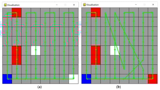
Figure 6.
UI for visualization. The blue cell represents the take-off and landing point. Red cells are candidate locations of recharging stations. White cells are locations that are actually used for recharging stations. (a) Drone path generated respectively by BF using two recharging stations. (b) Drone path generated respectively by BFKSA using only one recharging station.
4.2. Simulation Results and Discussion
The proposed BFKSA is compared to the naïve Back and Forth approach and the K-Simulated Annealing (KSA). KSA is the K-opt variant of the well-known simulated annealing (KSA). The main difference with BFKSA is the fact that KSA starts with a randomly generated initial solution. All the algorithms are implemented from scratch in Python. The source code is available on GitHub at the following address: https://github.com/Suns-group/SD-MRS-LF (Supplementary Materials).
Four metrics are used to compare approaches: the ability to find a feasible solution, the number of recharging stations, the completion time of the mission, and the total energy consumption.
Simulations results are discussed based on the size of the instances and the wind speed and direction. Figure 7, Figure 8, Figure 9 and Figure 10 display the results for feasibility, number of charging stations, mission completion time, and total energy consumption respectively on 8 × 8 instances. Figure 7 shows that the higher the wind speed, the lower the ability of all algorithms to find feasible solutions for all the approaches. This is explained by the fact that the drone must at times travel against the wind, and opposing strong winds can cause very large increases in energy consumption, according to Equation (21). Figure 7 and Figure 8 show that all the approaches provide 100% feasibility and equal numbers of charging stations for wind speed less than or equal to 2 m/s. However, for higher wind speeds the BFKSA outperforms other approaches in both feasibility and reduced number of charging stations, except for wind speed 4 m/s and wind direction 45°. This may be due to the fact that the initial back-and-forth movement used by BFKSA either aligns with 90° or 0°, whereas the optimal direction to avoid wind drag should be orthogonal to the wind direction 45°. It is plausible that the initial suboptimal alignment leads to the algorithm’s convergence to a suboptimal solution. On the other hand, KSA starts with a complete random solution and has a better chance of finding optimal drone path alignments.
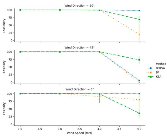
Figure 7.
Feasibility of the solutions for 8 8 instances with different wind speeds and directions.
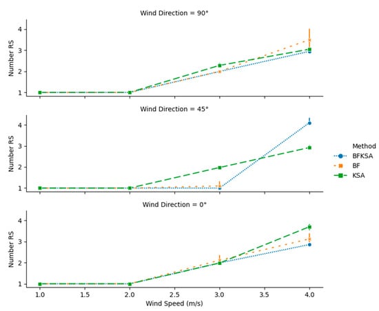
Figure 8.
Number of recharging stations for 8 8 Instances with different wind speeds and directions.
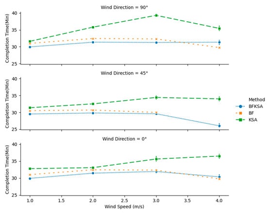
Figure 9.
Mission completion time for 8 8 instances with different wind speeds and directions.
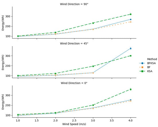
Figure 10.
Total energy consumption for 8 8 Instances with different wind speeds and directions.
Figure 9 and Figure 10 show the completion time and energy consumption respectively for 8 8 instances for the different wind scenarios. It is known from the literature that back and forth movement provides the most efficient energy consumption and mission completion time when wind speed is negligible. However, the figures show that BFKSA can provide a slight improvement in some cases for lower wind speeds. For other wind speeds, BFKSA gives results that are close to BF and better than KS, except for power consumption with wind direction 45°.
Detailed results for the 8 8 case are listed in Table A1, Table A2, Table A3, Table A4, Table A5 and Table A6 in Appendix A. An examination of the tables shows that BFKSA does not provide the smallest mission completion time only in two scenarios out of 12. The tables also show that each time BF finds a feasible solution, its energy consumption is close to the one of BFKSA, except in the cases where BFKSA provides a smaller number of recharging stations.
Figure 11, Figure 12, Figure 13 and Figure 14 display the results for feasibility, number of charging stations, mission completion time, and total energy consumption respectively on 16 × 16 instances. As was the case in 8 8 instances, the wind speed and direction heavily influence the ability to find feasible solutions. For wind speed higher than 2 m/s and wind direction different from 0°, none of the approaches is able to find a feasible solution. This justifies the holes in Figure 12, Figure 13 and Figure 14 for wind speed higher than 2 m/s and wind direction different from 0°.
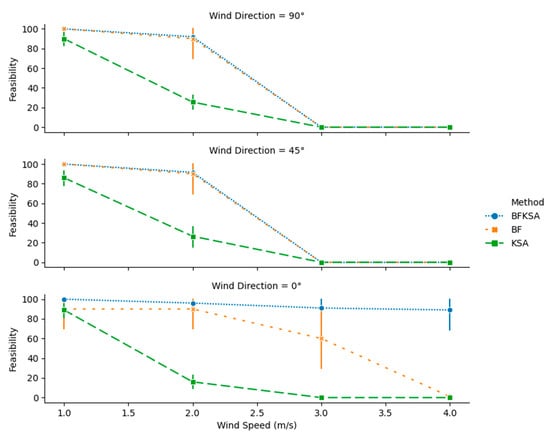
Figure 11.
Feasibility of the solutions for 16 16 Instances with different wind speeds and directions.
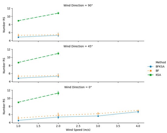
Figure 12.
Number of recharging station for 16 16 instances with different wind speeds and directions.
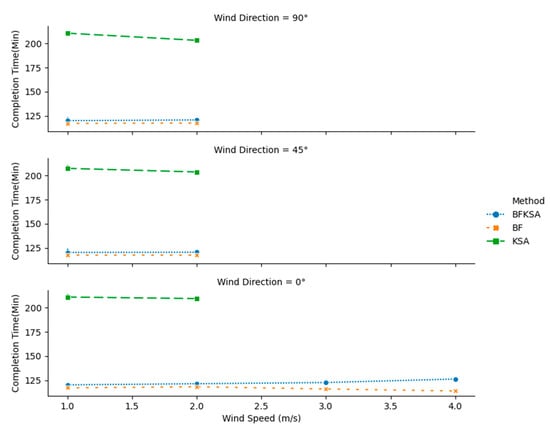
Figure 13.
Mission completion time for 16 16 instances with different wind speeds and directions.
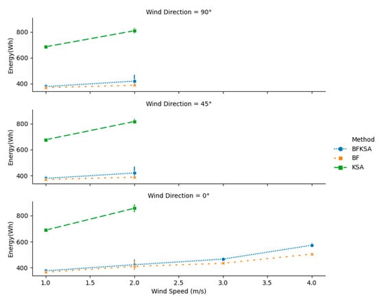
Figure 14.
Total energy consumption for 16 × 16 instances with different wind speeds and directions.
However, BFKSA manages to obtain close to 100% feasibility higher wind speeds and direction equals to 0°. In addition, Figure 12, Figure 13 and Figure 14 show that BFKSA provides the minimal number of recharging stations in all scenarios, as well as nearly matching BF in terms of completion time and energy consumption.
More detailed results for the 16 16 simulations are given in Table A7, Table A8, Table A9, Table A10, Table A11 and Table A12. The comparative performance for KSA is much worse for 16 than for 8 8. In particular, KSA sometimes requires more than twice the number of recharging stations and the total energy required by BFKSA.
All the above results show the dominance of BFKSA over the other approaches due to its ability to find a feasible solution with a minimum number of recharging stations.
5. Conclusions
The automatic surveillance of large farms using drones requires intelligent path planning that takes into account the drone’s limited range and optimizes the locations of recharging stations. In this work, we introduced the Single Drone Multiple Recharging Stations in Large Farm problem (SD-MRS-LF). The objectives were to minimize first the number of recharging stations and then the mission completion time. An approach called BFKSA based on a combination of BF (back-and-forth), K-opt, and simulated annealing (SA) has been proposed to solve the problem. Simulation results comparing BFKSA to BF and KSA have shown the superior performance of BFKSA with respect to its ability to find feasible solutions with a minimal number of charging stations. BFKSA provides the highest percentage of feasible solutions with the smallest number of recharging stations. In certain cases, BFKSA was able to provide a mission completion time and energy consumption smaller than the values provided by BF known to be effective solution.
In this work, the drone was constrained to visit each station only once. Removing this constraint can significantly reduce the number of recharging stations, but it requires a new formulation of the problem. In addition, we suppose each recharging station having an unlimited energy. In case the drone can visit the same recharging station more than once, a charging and discharging function of the recharging station should be considered for a more realistic scenario. Moreover, other optimization techniques can be explored, and the area of interest can be extended to random fields.
Supplementary Materials
The source code is available online at: https://github.com/Suns-group/SD-MRS-LF.
Author Contributions
Conceptualization, J.L.E.K.F.; Methodology, J.L.E.K.F., C.T., and I.K.B.; Software, I.K.B. and J.L.E.K.F.; Validation, J.L.E.K.F., I.K.B., C.T., M.D.F., and A.F; Formal analysis, J.L.E.K.F. and C.T.; Writing—original draft preparation, J.L.E.K.F.; Writing—review and editing, C.T., M.D.F., and A.F.; Visualization, J.L.E.K.F., C.T., and A.F.; Supervision, A.F; Funding acquisition, A.F. All authors have read and agreed to the published version of the manuscript.
Funding
This research received no external funding. The APC was funded by the University of Bremen.
Conflicts of Interest
The authors declare no conflict of interest.
Appendix A. Results from Simulations
Table A1.
Mean values of performance metrics on 8 8 instances with wind speed = 3 m/s, direction = 90°.
Table A1.
Mean values of performance metrics on 8 8 instances with wind speed = 3 m/s, direction = 90°.
| Feasibility (%) | Number of Recharging Station | Completion Time (min) | Energy Consumption (Wh) | |||||||||
|---|---|---|---|---|---|---|---|---|---|---|---|---|
| BF | KSA | BFKSA | BF | KSA | BFKSA | BF | KSA | BFKSA | BF | KSA | BFKSA | |
| Inst8_1 | 100 | 100 | 100 | 2 | 2.25 | 2 | 32.33 | 39.39 | 31.17 | 169.09 | 234.14 | 170.47 |
| Inst8_2 | 100 | 100 | 100 | 2 | 2.25 | 2 | 32.33 | 38.90 | 31.30 | 169.09 | 227.49 | 173.24 |
| Inst8_3 | 100 | 100 | 100 | 2 | 2.20 | 2 | 32.33 | 39.25 | 31.18 | 169.09 | 231.73 | 170.87 |
| Inst8_4 | 100 | 100 | 100 | 2 | 2.50 | 2 | 32.33 | 40.52 | 31.53 | 169.09 | 239.05 | 170.67 |
| Inst8_5 | 100 | 95 | 100 | 2 | 2.16 | 2 | 32.33 | 38.88 | 31.34 | 169.09 | 231.54 | 171.92 |
| Inst8_6 | 100 | 100 | 100 | 2 | 2.25 | 2 | 32.33 | 39.61 | 31.11 | 169.09 | 233.77 | 170.16 |
| Inst8_7 | 100 | 100 | 100 | 2 | 2.30 | 2 | 32.33 | 39.12 | 31.39 | 169.09 | 235.30 | 170.99 |
| Inst8_8 | 100 | 100 | 100 | 2 | 2.05 | 1.95 | 32.33 | 38.02 | 31.17 | 169.09 | 223.23 | 170.71 |
| Inst8_9 | 100 | 100 | 100 | 2 | 2.40 | 2 | 32.33 | 39.78 | 31.53 | 169.09 | 236.90 | 171.13 |
| Inst8_10 | 100 | 95 | 100 | 2 | 2.47 | 2 | 32.33 | 39.59 | 31.04 | 169.09 | 236.41 | 170.65 |
Table A2.
Mean values of performance metrics on 8 8 instances with wind speed = 3 m/s, direction = 45°.
Table A2.
Mean values of performance metrics on 8 8 instances with wind speed = 3 m/s, direction = 45°.
| Feasibility (%) | Number of Recharging Station | Completion Time (min) | Energy Consumption (Wh) | |||||||||
|---|---|---|---|---|---|---|---|---|---|---|---|---|
| BF | KSA | BFKSA | BF | KSA | BFKSA | BF | KSA | BFKSA | BF | KSA | BFKSA | |
| Inst8_1 | 100 | 100 | 100 | 1 | 2.00 | 1 | 29.98 | 34.22 | 29.28 | 127.84 | 193.74 | 127.32 |
| Inst8_2 | 100 | 100 | 100 | 1 | 1.95 | 1 | 29.98 | 34.40 | 29.45 | 127.84 | 191.31 | 126.58 |
| Inst8_3 | 100 | 100 | 100 | 1 | 1.90 | 1 | 29.98 | 33.10 | 29.46 | 127.84 | 185.37 | 128.51 |
| Inst8_4 | 100 | 100 | 100 | 2 | 2 | 1 | 29.98 | 33.91 | 31.31 | 127.84 | 192.25 | 139.31 |
| Inst8_5 | 100 | 100 | 100 | 1 | 2 | 1 | 29.98 | 35.03 | 29.11 | 127.84 | 195.83 | 129.24 |
| Inst8_6 | 100 | 100 | 100 | 1 | 1.90 | 1 | 29.98 | 33.98 | 29.23 | 127.84 | 187.46 | 127.94 |
| Inst8_7 | 100 | 100 | 100 | 1 | 1.95 | 1 | 29.98 | 34.20 | 29.61 | 127.84 | 194.30 | 127.48 |
| Inst8_8 | 100 | 100 | 100 | 1 | 1.95 | 1 | 29.98 | 33.65 | 29.55 | 127.84 | 193.49 | 126.83 |
| Inst8_9 | 100 | 100 | 100 | 1 | 2 | 1 | 29.98 | 35.73 | 29.68 | 127.84 | 209.81 | 127.46 |
| Inst8_10 | 100 | 100 | 100 | 1 | 2.10 | 1 | 29.98 | 36.02 | 29.35 | 127.84 | 205.57 | 128.17 |
Table A3.
Mean values of performance metrics on 8 8 instances with wind speed = 3 m/s, direction = 0°.
Table A3.
Mean values of performance metrics on 8 8 instances with wind speed = 3 m/s, direction = 0°.
| Feasibility (%) | Number of Recharging Station | Completion Time (min) | Energy Consumption (Wh) | |||||||||
|---|---|---|---|---|---|---|---|---|---|---|---|---|
| BF | KSA | BFKSA | BF | KSA | BFKSA | BF | KSA | BFKSA | BF | KSA | BFKSA | |
| Inst8_1 | 100 | 100 | 100 | 2 | 2 | 2 | 32.33 | 35.39 | 31.41 | 169.09 | 201.00 | 171.01 |
| Inst8_2 | 100 | 100 | 100 | 2 | 2 | 2 | 32.33 | 36.73 | 31.35 | 169.09 | 204.80 | 170.41 |
| Inst8_3 | 100 | 100 | 100 | 2 | 2 | 2 | 32.33 | 34.90 | 31.70 | 169.09 | 202.64 | 171.27 |
| Inst8_4 | 0 | 100 | 100 | - | 2 | 2 | - | 37.93 | 33.69 | - | 211.94 | 181.85 |
| Inst8_5 | 100 | 100 | 100 | 2 | 1.90 | 2 | 32.33 | 36.40 | 31.42 | 169.09 | 205.60 | 171.49 |
| Inst8_6 | 100 | 100 | 100 | 2 | 1.90 | 2 | 32.33 | 34.11 | 31.44 | 169.09 | 190.71 | 170.56 |
| Inst8_7 | 100 | 100 | 100 | 2 | 2 | 1.85 | 32.33 | 34.93 | 31.72 | 169.09 | 198.22 | 170.67 |
| Inst8_8 | 100 | 100 | 100 | 2 | 2 | 2 | 32.33 | 34.77 | 31.34 | 169.09 | 197.91 | 168.79 |
| Inst8_9 | 100 | 100 | 100 | 2 | 2 | 2 | 32.33 | 35.26 | 32.04 | 169.09 | 201.67 | 169.65 |
| Inst8_10 | 100 | 90 | 100 | 3 | 2 | 2 | 32.33 | 35.91 | 33.24 | 169.09 | 203.91 | 182.30 |
Table A4.
Mean values of performance metrics on 8 8 instances with wind speed = 4 m/s, direction = 90°.
Table A4.
Mean values of performance metrics on 8 8 instances with wind speed = 4 m/s, direction = 90°.
| Feasibility (%) | Number of Recharging Station | Completion Time (min) | Energy Consumption (Wh) | |||||||||
|---|---|---|---|---|---|---|---|---|---|---|---|---|
| BF | KSA | BFKSA | BF | KSA | BFKSA | BF | KSA | BFKSA | BF | KSA | BFKSA | |
| Inst8_1 | 100 | 75 | 100 | 3 | 3.07 | 3 | 29.77 | 35.31 | 28.80 | 243.69 | 318.33 | 253.66 |
| Inst8_2 | 0 | 70 | 85 | - | 3.07 | 2.94 | - | 34.60 | 31.90 | - | 319.68 | 264.94 |
| Inst8_3 | 0 | 65 | 100 | - | 3.15 | 3 | - | 35.73 | 31.84 | - | 323.33 | 264.61 |
| Inst8_4 | 0 | 35 | 100 | - | 2.71 | 2.95 | - | 34.69 | 32.35 | - | 298.96 | 278.56 |
| Inst8_5 | 0 | 65 | 100 | - | 3.15 | 2.95 | - | 33.58 | 30.84 | - | 301.53 | 258.17 |
| Inst8_6 | 0 | 80 | 100 | - | 3.06 | 2.95 | - | 36.19 | 31.45 | - | 312.23 | 270.15 |
| Inst8_7 | 0 | 90 | 100 | - | 3.22 | 3 | - | 37.05 | 32.45 | - | 341.63 | 289.55 |
| Inst8_8 | 0 | 95 | 95 | - | 3.11 | 2.89 | - | 36.31 | 30.92 | - | 314.37 | 271.26 |
| Inst8_9 | 0 | 70 | 100 | - | 3.07 | 2.85 | - | 36.64 | 31.94 | - | 331.92 | 271.32 |
| Inst8_10 | 100 | 45 | 100 | 4 | 2.89 | 2.95 | 29.77 | 34.37 | 30.90 | 243.69 | 345.96 | 270.49 |
Table A5.
Mean values of performance metrics on 8 8 instances with wind speed = 4 m/s, direction = 45°.
Table A5.
Mean values of performance metrics on 8 8 instances with wind speed = 4 m/s, direction = 45°.
| Feasibility (%) | Number of Recharging Station | Completion Time (min) | Energy Consumption (Wh) | |||||||||
|---|---|---|---|---|---|---|---|---|---|---|---|---|
| BF | KSA | BFKSA | BF | KSA | BFKSA | BF | KSA | BFKSA | BF | KSA | BFKSA | |
| Inst8_1 | 0 | 75 | 10 | - | 3.13 | 4.5 | - | 33.80 | 25.48 | - | 301.36 | 363.18 |
| Inst8_2 | 0 | 90 | 5 | - | 2.94 | 4 | - | 35.58 | 25.96 | - | 306.98 | 383.01 |
| Inst8_3 | 0 | 95 | 0 | - | 2.89 | - | - | 35.15 | - | - | 295.41 | - |
| Inst8_4 | 0 | 50 | 0 | - | 2.70 | - | - | 32.68 | - | - | 283.64 | - |
| Inst8_5 | 0 | 70 | 25 | - | 2.86 | 4 | - | 32.58 | 27.33 | - | 283.07 | 383.47 |
| Inst8_6 | 0 | 50 | 10 | - | 3.10 | 4 | - | 32.84 | 25.49 | - | 304.37 | 359.28 |
| Inst8_7 | 0 | 90 | 10 | - | 3.06 | 4 | - | 35.04 | 25.87 | - | 314.40 | 382.36 |
| Inst8_8 | 0 | 90 | 0 | - | 2.89 | - | - | 34.71 | - | - | 308.74 | - |
| Inst8_9 | 0 | 80 | 0 | - | 2.88 | - | - | 34.18 | - | - | 312.63 | - |
| Inst8_10 | 0 | 45 | 0 | - | 2.78 | - | - | 33.54 | - | - | 294.10 | - |
Table A6.
Mean values of performance metrics on 8 8 instances with wind speed = 4 m/s, direction = 0°.
Table A6.
Mean values of performance metrics on 8 8 instances with wind speed = 4 m/s, direction = 0°.
| Feasibility (%) | Number of Recharging Station | Completion Time (min) | Energy Consumption (Wh) | |||||||||
|---|---|---|---|---|---|---|---|---|---|---|---|---|
| BF | KSA | BFKSA | BF | KSA | BFKSA | BF | KSA | BFKSA | BF | KSA | BFKSA | |
| Inst8_1 | 100 | 45 | 100 | 3 | 3.56 | 2.8 | 29.77 | 35.76 | 29.71 | 243.69 | 367.00 | 247.71 |
| Inst8_2 | 100 | 50 | 100 | 3 | 3.70 | 3 | 29.77 | 36.00 | 29.47 | 243.69 | 349.26 | 244.48 |
| Inst8_3 | 0 | 45 | 100 | - | 3.78 | 2.9 | - | 37.18 | 31.94 | - | 377.64 | 277.93 |
| Inst8_4 | 0 | 0 | 100 | - | - | 3 | - | - | 32.23 | - | - | 267.14 |
| Inst8_5 | 100 | 25 | 100 | 3 | 3.80 | 2.6 | 29.77 | 35.05 | 29.98 | 243.69 | 372.78 | 246.58 |
| Inst8_6 | 100 | 50 | 100 | 3 | 3.70 | 2.8 | 29.77 | 37.17 | 30.06 | 243.69 | 369.74 | 252.76 |
| Inst8_7 | 100 | 55 | 100 | 3 | 3.91 | 2.7 | 29.77 | 37.50 | 29.70 | 243.69 | 361.09 | 244.90 |
| Inst8_8 | 100 | 60 | 100 | 4 | 3.83 | 3 | 29.77 | 37.59 | 30.63 | 243.69 | 358.71 | 256.23 |
| Inst8_9 | 100 | 30 | 100 | 3 | 3.33 | 2.9 | 29.77 | 35.83 | 29.97 | 243.69 | 325.65 | 244.57 |
| Inst8_10 | 100 | 0 | 100 | 3 | - | 2.85 | 29.77 | - | 29.81 | 243.69 | - | 243.42 |
Table A7.
Values of performance metrics on 16 16 instances with wind speed = 1 m/s, direction = 90°.
Table A7.
Values of performance metrics on 16 16 instances with wind speed = 1 m/s, direction = 90°.
| Feasibility (%) | Number of Recharging Station | Completion Time (min) | Energy Consumption (Wh) | |||||||||
|---|---|---|---|---|---|---|---|---|---|---|---|---|
| BF | KSA | BFKSA | BF | KSA | BFKSA | BF | KSA | BFKSA | BF | KSA | BFKSA | |
| Inst16_1 | 100 | 95 | 100 | 5 | 8.95 | 4.55 | 117.23 | 213.13 | 118.61 | 365.61 | 688.27 | 370.35 |
| Inst16_2 | 100 | 75 | 100 | 5 | 9.2 | 5 | 117.23 | 210.77 | 117.17 | 365.61 | 699.65 | 365.39 |
| Inst16_3 | 100 | 100 | 100 | 5 | 8.75 | 4.95 | 117.23 | 214.71 | 117.79 | 365.61 | 690.99 | 367.52 |
| Inst16_4 | 100 | 65 | 100 | 6 | 8.85 | 5.1 | 117.23 | 200.31 | 130.75 | 407.59 | 667.21 | 436.48 |
| Inst16_5 | 100 | 100 | 100 | 6 | 9 | 5 | 117.23 | 214.93 | 123.34 | 365.61 | 692.8 | 385.7 |
| Inst16_6 | 100 | 100 | 100 | 5 | 8.85 | 4.6 | 117.23 | 211.59 | 117.51 | 365.61 | 681.78 | 366.53 |
| Inst16_7 | 100 | 90 | 100 | 5 | 8.89 | 4.95 | 117.23 | 211.94 | 117.37 | 365.61 | 689.96 | 366.04 |
| Inst16_8 | 100 | 100 | 100 | 5 | 8.95 | 4.55 | 117.23 | 210.54 | 117.93 | 365.61 | 677.76 | 367.91 |
| Inst16_9 | 100 | 90 | 100 | 6 | 9 | 5 | 117.23 | 209.5 | 123.24 | 365.61 | 679.81 | 385.51 |
| Inst16_10 | 100 | 85 | 100 | 5 | 8.88 | 4.9 | 117.23 | 209.86 | 117.61 | 365.61 | 682.68 | 366.84 |
Table A8.
Values of performance metrics on 16 16 instances with wind speed = 1 m/s, direction = 45°.
Table A8.
Values of performance metrics on 16 16 instances with wind speed = 1 m/s, direction = 45°.
| Feasibility (%) | Number of Recharging Station | Completion Time (min) | Energy Consumption (Wh) | |||||||||
|---|---|---|---|---|---|---|---|---|---|---|---|---|
| BF | KSA | BFKSA | BF | KSA | BFKSA | BF | KSA | BFKSA | BF | KSA | BFKSA | |
| Inst16_1 | 100 | 90 | 100 | 5 | 8.72 | 4.35 | 117.23 | 211.2 | 119.05 | 365.61 | 687.16 | 371.64 |
| Inst16_2 | 100 | 75 | 100 | 5 | 8.67 | 5 | 117.23 | 202.92 | 117.14 | 365.61 | 675.12 | 365.32 |
| Inst16_3 | 100 | 95 | 100 | 5 | 8.74 | 4.95 | 117.23 | 207.91 | 117.37 | 365.61 | 671.58 | 366.12 |
| Inst16_4 | 100 | 65 | 100 | 6 | 8.46 | 5 | 121.41 | 201.46 | 132.76 | 407.59 | 664.88 | 442.41 |
| Inst16_5 | 100 | 85 | 100 | 6 | 8.41 | 4.8 | 117.23 | 203.29 | 123.29 | 365.61 | 661.4 | 385.89 |
| Inst16_6 | 100 | 100 | 100 | 5 | 8.9 | 4.8 | 117.23 | 214.75 | 117.59 | 365.61 | 691.2 | 366.84 |
| Inst16_7 | 100 | 80 | 100 | 5 | 8.56 | 5 | 117.23 | 206.86 | 117.13 | 365.61 | 677.07 | 365.28 |
| Inst16_8 | 100 | 100 | 100 | 5 | 8.7 | 4.5 | 117.23 | 208.23 | 118.93 | 365.61 | 670.6 | 370.98 |
| Inst16_9 | 100 | 95 | 100 | 6 | 8.84 | 5 | 117.23 | 209.34 | 122.77 | 365.61 | 676.53 | 384.13 |
| Inst16_10 | 100 | 75 | 100 | 5 | 9.2 | 4.85 | 117.23 | 208.74 | 117.75 | 365.61 | 689.99 | 367.35 |
Table A9.
Values of performance metrics on 16 16 instances with wind speed = 1 m/s, direction = 0°.
Table A9.
Values of performance metrics on 16 16 instances with wind speed = 1 m/s, direction = 0°.
| Feasibility (%) | Number of Recharging Station | Completion Time (min) | Energy Consumption (Wh) | |||||||||
|---|---|---|---|---|---|---|---|---|---|---|---|---|
| BF | KSA | BFKSA | BF | KSA | BFKSA | BF | KSA | BFKSA | BF | KSA | BFKSA | |
| Inst16_1 | 100 | 95 | 100 | 5 | 9.05 | 4.05 | 117.23 | 211 | 119.53 | 365.61 | 685.21 | 373.21 |
| Inst16_2 | 100 | 70 | 100 | 5 | 8.86 | 4.65 | 117.23 | 204.24 | 118.39 | 365.61 | 682.22 | 369.45 |
| Inst16_3 | 100 | 90 | 100 | 6 | 9.17 | 5 | 117.23 | 214.26 | 123.74 | 365.61 | 694.76 | 387.25 |
| Inst16_4 | 0 | 65 | 100 | - | 9.08 | 5 | - | 206.48 | 127.45 | - | 678.03 | 398.99 |
| Inst16_5 | 100 | 95 | 100 | 5 | 8.89 | 4.3 | 117.23 | 211.07 | 118.55 | 365.61 | 686.13 | 369.96 |
| Inst16_6 | 100 | 100 | 100 | 5 | 9.2 | 4.65 | 117.23 | 215.61 | 118.04 | 365.61 | 697.04 | 368.24 |
| Inst16_7 | 100 | 90 | 100 | 5 | 9 | 4.55 | 117.23 | 207.57 | 117.66 | 365.61 | 673.79 | 366.93 |
| Inst16_8 | 100 | 95 | 100 | 4 | 8.95 | 4 | 117.23 | 212.27 | 117.2 | 365.61 | 695.5 | 365.51 |
| Inst16_9 | 100 | 100 | 100 | 6 | 8.9 | 5 | 117.23 | 213.94 | 123.15 | 365.61 | 690.82 | 385.23 |
| Inst16_10 | 100 | 90 | 100 | 5 | 9.06 | 4.05 | 117.23 | 213.61 | 119.68 | 365.61 | 700.72 | 373.65 |
Table A10.
Values of performance metrics on 16 16 instances with wind speed = 2 m/s, direction = 90°.
Table A10.
Values of performance metrics on 16 16 instances with wind speed = 2 m/s, direction = 90°.
| Feasibility (%) | Number of Recharging Station | Completion Time (min) | Energy Consumption (Wh) | |||||||||
|---|---|---|---|---|---|---|---|---|---|---|---|---|
| BF | KSA | BFKSA | BF | KSA | BFKSA | BF | KSA | BFKSA | BF | KSA | BFKSA | |
| Inst16_1 | 100 | 30 | 100 | 5 | 11 | 5 | 117.62 | 205.66 | 117.55 | 387.9 | 800.06 | 387.5 |
| Inst16_2 | 100 | 15 | 100 | 6 | 11.33 | 5 | 117.62 | 200.25 | 122.38 | 387.9 | 849.84 | 408.39 |
| Inst16_3 | 100 | 40 | 100 | 6 | 10.5 | 5 | 117.62 | 207.15 | 126.12 | 387.9 | 808.05 | 423.86 |
| Inst16_4 | 0 | 10 | 20 | - | 11 | 8 | - | 198.72 | 125.8 | - | 795.34 | 606.15 |
| Inst16_5 | 100 | 35 | 100 | 6 | 10.71 | 5 | 117.62 | 205.72 | 123.41 | 387.9 | 790.25 | 411.09 |
| Inst16_6 | 100 | 45 | 100 | 6 | 11 | 5 | 117.62 | 208.98 | 122.62 | 387.9 | 840.03 | 409.37 |
| Inst16_7 | 100 | 10 | 100 | 5 | 10 | 5 | 117.62 | 201.56 | 117.51 | 387.9 | 758.86 | 387.4 |
| Inst16_8 | 100 | 30 | 100 | 5 | 10.17 | 5 | 117.62 | 203.88 | 117.48 | 387.9 | 783.53 | 387.43 |
| Inst16_9 | 100 | 15 | 100 | 5 | 11.33 | 4.95 | 117.62 | 200.54 | 117.84 | 387.9 | 833.57 | 388.05 |
| Inst16_10 | 100 | 25 | 100 | 5 | 11 | 5 | 117.62 | 200.55 | 117.49 | 387.9 | 825.01 | 387.44 |
Table A11.
Values of performance metrics on 16 16 instances with wind speed = 2 m/s, direction = 45°.
Table A11.
Values of performance metrics on 16 16 instances with wind speed = 2 m/s, direction = 45°.
| Feasibility (%) | Number of Recharging Station | Completion Time (min) | Energy Consumption (Wh) | |||||||||
|---|---|---|---|---|---|---|---|---|---|---|---|---|
| BF | KSA | BFKSA | BF | KSA | BFKSA | BF | KSA | BFKSA | BF | KSA | BFKSA | |
| Inst16_1 | 100 | 45 | 100 | 5 | 11.11 | 5 | 117.62 | 209.6 | 117.6 | 387.9 | 846.94 | 387.8 |
| Inst16_2 | 100 | 5 | 100 | 6 | 12 | 5 | 117.62 | 201.71 | 121.6 | 387.9 | 855.09 | 405.19 |
| Inst16_3 | 100 | 55 | 100 | 6 | 10.73 | 5 | 117.62 | 204.04 | 126.41 | 387.9 | 805.49 | 425.79 |
| Inst16_4 | 0 | 10 | 15 | - | 11 | 8 | - | 200.06 | 125.76 | - | 803.45 | 615.34 |
| Inst16_5 | 100 | 25 | 100 | 6 | 10.2 | 5 | 117.62 | 202.68 | 122.57 | 387.9 | 785.22 | 411.15 |
| Inst16_6 | 100 | 40 | 100 | 6 | 11 | 5 | 117.62 | 207.14 | 121.7 | 387.9 | 820.39 | 405.05 |
| Inst16_7 | 100 | 20 | 100 | 5 | 10.5 | 5 | 117.62 | 199.98 | 117.6 | 387.9 | 789.66 | 387.84 |
| Inst16_8 | 100 | 40 | 100 | 5 | 10.88 | 5 | 117.62 | 206 | 117.53 | 387.9 | 800.92 | 387.44 |
| Inst16_9 | 100 | 10 | 100 | 5 | 11.5 | 5 | 117.62 | 204.42 | 117.49 | 387.9 | 856.11 | 387.39 |
| Inst16_10 | 100 | 15 | 100 | 5 | 10.67 | 5 | 117.62 | 201.68 | 117.58 | 387.9 | 807.72 | 387.69 |
Table A12.
Values of performance metrics on 16 16 instances with wind speed = 2 m/s, direction = 0°.
Table A12.
Values of performance metrics on 16 16 instances with wind speed = 2 m/s, direction = 0°.
| Feasibility (%) | Number of Recharging Station | Completion Time (min) | Energy Consumption (Wh) | |||||||||
|---|---|---|---|---|---|---|---|---|---|---|---|---|
| BF | KSA | BFKSA | BF | KSA | BFKSA | BF | KSA | BFKSA | BF | KSA | BFKSA | |
| Inst16_1 | 100 | 10 | 100 | 5 | 11.5 | 5 | 117.62 | 210.69 | 117.6 | 387.9 | 860.01 | 387.84 |
| Inst16_2 | 100 | 10 | 100 | 5 | 11.5 | 5 | 117.62 | 204.61 | 117.55 | 387.9 | 921.26 | 387.7 |
| Inst16_3 | 100 | 20 | 100 | 6 | 11.5 | 5 | 117.62 | 204.84 | 124.93 | 387.9 | 843.27 | 415.64 |
| Inst16_4 | 0 | 5 | 60 | - | 10 | 5.92 | - | 211.42 | 125.72 | - | 776.78 | 444.95 |
| Inst16_5 | 100 | 35 | 100 | 6 | 10.86 | 5 | 117.62 | 211.5 | 122.64 | 387.9 | 867.79 | 407.84 |
| Inst16_6 | 100 | 20 | 100 | 5 | 12.25 | 5 | 117.62 | 212.81 | 117.48 | 387.9 | 900.99 | 387.34 |
| Inst16_7 | 100 | 20 | 100 | 8 | 11.5 | 8 | 124.53 | 210.44 | 124.47 | 585.97 | 840.68 | 586 |
| Inst16_8 | 100 | 30 | 100 | 5 | 11.83 | 4.75 | 117.62 | 211.65 | 118.12 | 387.9 | 873.25 | 389.2 |
| Inst16_9 | 100 | 10 | 100 | 6 | 10.5 | 5 | 117.62 | 206.68 | 123.14 | 387.9 | 827.71 | 410.95 |
| Inst16_10 | 100 | 0 | 100 | 6 | - | 5 | 117.62 | - | 123.23 | 387.9 | - | 409.35 |
References
- Mazur, M.; Wisniewski, A.; McMillan, J. Clarity from above: PwC global report on the commercial applications of drone technology. Wars. Drone Powered Solut. PriceWater House Coopers 2016. Available online: https://www.pwc.pl/pl/pdf/clarity-from-above-pwc.pdf (accessed on 20 May 2020).
- Lottes, P.; Khanna, R.; Pfeifer, J.; Siegwart, R.; Stachniss, C. UAV-based crop and weed classification for smart farming. In Proceedings of the 2017 IEEE International Conference on Robotics and Automation (ICRA); IEEE: New York, NY, USA; pp. 3024–3031.
- Becerra, V.M. Autonomous Control of Unmanned Aerial Vehicles. Electronics 2019, 8, 452. [Google Scholar] [CrossRef]
- Choset, H. Coverage for robotics–A survey of recent results. Ann. Math. Artif. Intell. 2001, 31, 113–126. [Google Scholar] [CrossRef]
- Kakaes, K.; Greenword, F.; Lippincott, M.; Dosemagen, S.; Meier, P.; Wich, S.A. Drones and Aerial Observation: New Technologies for Property Rights. Hum. Rights Glob. Dev. Primer New Am. 2015, 2015, 514–519. [Google Scholar]
- Huang, W.H. Optimal line-sweep-based decompositions for coverage algorithms. In Proceedings of the 2001 ICRA. IEEE International Conference on Robotics and Automation (Cat. No. 01CH37164); IEEE: New York, NY, USA, 2001; Volume 1, pp. 27–32. [Google Scholar]
- Galceran, E.; Carreras, M. A survey on coverage path planning for robotics. Robot. Auton. Syst. 2013, 61, 1258–1276. [Google Scholar] [CrossRef]
- Jiao, Y.-S.; Wang, X.-M.; Chen, H.; Li, Y. Research on the coverage path planning of uavs for polygon areas. In Proceedings of the 2010 5th IEEE Conference on Industrial Electronics and Applications; IEEE: New York, NY, USA, 2010; pp. 1467–1472. [Google Scholar]
- Sadat, S.A.; Wawerla, J.; Vaughan, R. Fractal trajectories for online non-uniform aerial coverage. In Proceedings of the 2015 IEEE International Conference on Robotics and Automation (ICRA); IEEE: New York, NY, USA, 2015; pp. 2971–2976. [Google Scholar]
- Cabreira, T.M.; Brisolara, L.B.; Ferreira, P.R., Jr. Survey on Coverage Path Planning with Unmanned Aerial Vehicles. Drones 2019, 3, 4. [Google Scholar] [CrossRef]
- Bushaw, J.D.; Ringelman, K.M.; Rohwer, F.C. Applications of Unmanned Aerial Vehicles to Survey Mesocarnivores. Drones 2019, 3, 28. [Google Scholar] [CrossRef]
- Collins, M.D. Using a Drone to Search for the Ivory-Billed Woodpecker (Campephilus principalis). Drones 2018, 2, 11. [Google Scholar] [CrossRef]
- Choi, C.H.; Jang, H.J.; Lim, S.G.; Lim, H.C.; Cho, S.H.; Gaponov, I. Automatic wireless drone charging station creating essential environment for continuous drone operation. In Proceedings of the 2016 International Conference on Control, Automation and Information Sciences (ICCAIS); IEEE: New York, NY, USA, 2016; pp. 132–136. [Google Scholar]
- Raciti, A.; Rizzo, S.A.; Susinni, G. Drone charging stations over the buildings based on a wireless power transfer system. In Proceedings of the 2018 IEEE/IAS 54th Industrial and Commercial Power Systems Technical Conference (I&CPS); IEEE: New York, NY, USA, 2018; pp. 1–6. [Google Scholar]
- Feng, Y.; Zhang, C.; Baek, S.; Rawashdeh, S.; Mohammadi, A. Autonomous Landing of a UAV on a Moving Platform Using Model Predictive Control. Drones 2018, 2, 34. [Google Scholar] [CrossRef]
- Kim, S.J.; Lim, G.J. A Hybrid Battery Charging Approach for Drone-Aided Border Surveillance Scheduling. Drones 2018, 2, 38. [Google Scholar] [CrossRef]
- Tseng, C.-M.; Chau, C.-K.; Elbassioni, K.M.; Khonji, M. Flight tour planning with recharging optimization for battery-operated autonomous drones. CoRR 2017, Abs170310049. [Google Scholar]
- Trotta, A.; Felice, M.D.; Montori, F.; Chowdhury, K.R.; Bononi, L. Joint Coverage, Connectivity, and Charging Strategies for Distributed UAV Networks. IEEE Trans. Robot. 2018, 34, 883–900. [Google Scholar] [CrossRef]
- Hong, I.; Kuby, M.; Murray, A.T. A range-restricted recharging station coverage model for drone delivery service planning. Transp. Res. Part. C Emerg. Technol. 2018, 90, 198–212. [Google Scholar] [CrossRef]
- Editor, D. Pilot-free, Heisha C200 Drone Charging Solutions for Automated Drone Applications. Droneblog. Available online: https://www.droneblog.com/2019/06/28/pilot-free-heisha-c200-drone-charging-solutions-for-automated-drone-applications/ (accessed on 2 May 2020).
- Hwang, M.; Cha, H.-R.; Jung, S.Y. Practical endurance estimation for minimizing energy consumption of multirotor unmanned aerial vehicles. Energies 2018, 11, 2221. [Google Scholar] [CrossRef]
- Dorling, K.; Heinrichs, J.; Messier, G.G.; Magierowski, S. Vehicle routing problems for drone delivery. IEEE Trans. Syst. Man Cybern. Syst. 2016, 47, 70–85. [Google Scholar] [CrossRef]
- Tseng, C.-M.; Chau, C.-K.; Elbassioni, K.; Khonji, M. Autonomous Recharging and Flight Mission Planning for Battery-operated Autonomous Drones. arXiv 2017, arXiv:170310049 Cs. [Google Scholar]
- Yang, C.-H.; Tsai, M.-H.; Kang, S.-C.; Hung, C.-Y. UAV path planning method for digital terrain model reconstruction–A debris fan example. Autom. Constr. 2018, 93, 214–230. [Google Scholar] [CrossRef]
- Shafian, S.; Rajan, N.; Schnell, R.; Bagavathiannan, M.; Valasek, J.; Shi, Y.; Olsenholler, J. Unmanned aerial systems-based remote sensing for monitoring sorghum growth and development. PLoS ONE 2018, 13, e0196605. [Google Scholar] [CrossRef] [PubMed]
- Tennekes, H. The Simple Science of Flight: From Insects to Jumbo Jets; MIT Press: Cambridge, MA, USA, 2009. [Google Scholar]
- Hill, P.G.; Peterson, C.R. Mechanics and Thermodynamics of Propulsion; Addison-Wesley Publishing Company: Boston, MA, USA, 1992; p. 764. [Google Scholar]
- Thibbotuwawa, A.; Nielsen, P.; Zbigniew, B.; Bocewicz, G. Energy consumption in unmanned aerial vehicles: A review of energy consumption models and their relation to the UAV routing. In Proceedings of the International Conference on Information Systems Architecture and Technology; Springer: Berlin, Germany, 2018; pp. 173–184. [Google Scholar]
© 2020 by the authors. Licensee MDPI, Basel, Switzerland. This article is an open access article distributed under the terms and conditions of the Creative Commons Attribution (CC BY) license (http://creativecommons.org/licenses/by/4.0/).