Article

Asymmetries in the Disturbance Compensation Methods for the Stable and Unstable First Order Plants

1
Institute of Automotive Mechatronics, Faculty of Electrical Engineering and Information Technology, Slovak University of Technology in Bratislava, 812 19 Bratislava, Slovakia
2
Department of Computer Automation and Control, J. Stefan Institute, SI-1000 Ljubljana, Slovenia
*
Author to whom correspondence should be addressed.
Symmetry 2020, 12(10), 1595; https://doi.org/10.3390/sym12101595
Submission received: 27 August 2020 / Revised: 20 September 2020 / Accepted: 21 September 2020 / Published: 25 September 2020
(This article belongs to the Section Engineering and Materials)

Abstract

:
This paper analyzes the first-order and first-order time-delayed systems control approaches, focusing mainly on unstable systems. First, it discusses asymmetries between the disturbance observer-based (DOB) control with decoupled tracking and the disturbance rejection responses, stressing applications to stable and unstable plants. The paper analyzes some DOB-based control solutions for unstable systems which do not use internal closed-loop stabilization. The novelty of the paper is thorough study accompanied with a comprehensive explanation of the differences between two distinct approaches: the transfer-function- and the closed-loop-based feedforward control approach from the point of view of control constraints. It is clearly illustrated that the main cause of instability of DOB-based approaches, applied to unstable systems, is given by their effort to impose on the system the unstable dynamics of the chosen nominal process model. It is also shown that the closed-loop stability of the DOB-based control, applied to the unstable systems, can be restored by using the supervising reference model control (RMC). The main novelty of the proposed approach is that its eliminates the mentioned stability problems while maintaining the full functionality of the chosen control structures. RMC has so far only been implemented for generating a setpoint feedforward signal. However, by generalization of this approach for disturbance rejection, the methodology of DOB design, based on nominal models, can be extended to the control of unstable systems. Without the use of disturbance reference models, the interactions of the master stabilizer with disturbance compensation cannot be eliminated. Without the internal stabilization, the stable transients can only be achieved by designing controllers based on stable models, instead of unstable ones. The existing modifications of DOB-based schemes for unstable plants, proposed in some references, are shown to lead to traditional Proportional-Integrative (PI) control, thus losing all the advantages over the PI controllers. In all the considered structures, the role of integrating models is also emphasized.

1. Introduction

The increase of computing power and functionality of industrial and embedded control solutions, together with the development of communication networks, leads to the explosion of automatic control applications in all areas of our lives. The control solutions should be simple, but, due to increasing performance demands, should also take into account the process time-delays at control design stage.
The simplicity of solutions could be obtained by reducing the plant model into the first-order time-delayed (FOTD) process, which could sufficiently well describe more complex processes, as well. Therefore, the FOTD processes, or in their simplest form of integral plus dead-time processes (IPDT), are among the most frequently used models in practice [1]. If the controller structure contains the delayed process model, the controller is usually denoted as the dead-time compensator (DTC). It is interesting to mention that the FOTD process model parameters are frequently used in many Proportional-Integral-Derivative (PID) controller tuning methods for the last eight decades. Since modeling of pure time-delays by analog circuitry is very limited in practice, the history of DTC controllers is much shorter, since it is tightly related to the development of digital control. The first DTCs included the Smith Predictor (SP) [2]. It could only be used to control stable FOTD systems.
After several modifications with gradually improved performance, the first dead-beat DTC applicable to all stable, integrative and unstable systems [3] was designed using the (sometime later introduced notion of) extended state observer (ESO) within the state-space approach. In constrained control, it guaranteed time-suboptimal performance. In addition to the disturbance observer (DOB) of the input disturbance, its non-delayed actual plant output value was also reconstructed from the measured delayed output. The basic design was then extended by a polynomial approach, yielding very simple relationships applicable to any integer ratio of the dead-time and the sampling period. Both reconstructed variables were used in combination with the two-degrees-of-freedom (2DOF) stabilizing Proportional (P) control.
Several different DTCs, numerous based on SP, are existing. In general, the solutions can be categorized as the dead-time elimination (by removing the transport delay from the loop characteristic polynomial [4]), or the solutions based on disturbance and actual output reconstruction from its delayed measurement, yielding some type of prediction [3,4,5].
The SP may be understood and developed more easily when it is interpreted as a setpoint feedforward term, extended by an output disturbance reconstruction and compensation term [6,7]. Here, we will develop a corresponding structure considering the input disturbance reconstruction and compensation.
In recent decades, the number of articles devoted to the control of time-delayed systems, using different types of DTCs, significantly increased (see, e.g., Reference [6,8,9,10,11,12] and the references therein). Although the mentioned articles bring numerous impressive and useful results, especially for unstable systems, some of them should be discussed in more details, since the proposed solutions therein might lead to inherently unstable design. Due to the inherent stability problems with the mentioned DTCs, the overall control solutions, including the undergraduate courses in systems and control engineering, are not so popular, especially when compared to the classical PID control [13]. In this work, we will clearly show some of the logical inconsistencies (even bordering on errors) on DTC designs for unstable processes that might be the main reason for their lower popularity. Besides the inconsistencies, the paper will also suggest some ways to improve (correct) the mentioned designs.
In both DTC and PID control design, the use of a model-based approach has been additionally extended. Such extended controller design is based on the model of the controlled process and the model of the required closed-loop system. The term “internal model control” (IMC) was frequently used in the mentioned extended approach, where both, the PID control [14] or DOB-based control [15], can be applied besides the output disturbance reconstruction scheme proposed in Reference [16]. Its key limitation is that, in the basic version, it may be used just on stable processes.
One of the most commonly used design of the PI and the PID controllers is based on a simplified replacement of the process delay model by the first order transfer function [14]. An interesting paradox is that the author declares that SPs are more sensitive on process changes than the PI and the PID controllers [17]. Here, we will not get into the details but will, rather, focus on some of unclear aspects of designing DTCs for unstable FOTDs (UFOTDs). To clearly understand the stability problems when dealing with unstable FOTD (UFOTD) processes, we will first focus on a simpler unstable first-order (UFO) process, where the closed-loop stability problems are equivalent but can be analyzed, solved and explained in a simpler way. We will also show that the existing DTC modifications for unstable systems are actually equivalent to solutions for the PI regulators [8,9], which is a paradox since DTCs have been designed to exceed the performance of the traditional PI and PID controllers. Furthermore, it will be shown that the main difference between the IMC and the SP approach becomes apparent when dealing with constrained systems. Moreover, the IMC with DOB terms, based on a setpoint feedforward approach, can be designed even for unstable systems. When augmented by the reference closed-loop model approach and the additional stabilizing controller, the IMC with DOB may be still maintaining full functionality, guaranteeing not just the stable closed-loop responses but also providing the additional data about the acting disturbances.

2. Problem Formulation

In the following, we will briefly deal with control structures derived from a simple feedforward control and with the plant stabilization problem. In order to show their key features and hidden attributes, the first order plants without additional delays will be considered firstly described as
S s = Y ( s ) U ( s ) = K s s + a .
Thereby, Y ( s ) and U ( s ) correspond to Laplace transforms of the plant output y ( t ) and of the plant input (controller output) u ( t ) , or u w f ( t ) . When wishing to stress possible differences among the considered plant and its model, over-lined symbols will be used for model parameters:
S ¯ s = K ¯ s s + a ¯ .

2.1. Feedforward Control

Some first-order control methods can be considered as an extension of feedforward control, while the others can be taken as a modification of the stabilizing proportional controller.
A feasible feedforward control of the first order plant (2) may be implemented by extending the plant model inversion by a low-pass filter Q w ( s ) of at least the first order
C w ( s ) = U w f ( s ) W ( s ) = Q w ( s ) S ¯ ( s ) = s + a ¯ K ¯ s ( 1 + T c s ) ; Q w ( s ) = 1 1 + T c s .
The tuning parameter T c represents a time constant of the corresponding setpoint tracking which characterizes speed of the transients towards the reference setpoint variable.

2.2. Stabilizing P Control

When accomplishing a feedback based on measuring output of the plant y ( t ) , the pole-assignment proportional (P) control with the pole λ = 1 / T c (Figure 1a) given by equations:
u = K P ( w y ) + a ¯ w / K ¯ s ; K P = ( λ + a ¯ ) / K ¯ s = ( 1 / T c a ¯ ) / K ¯ s
yields for S ( s ) = S ¯ ( s ) the following input-output behavior
F w y = Y ( s ) W ( s ) = 1 T c s + 1 ; I A E w = T c ; T c = 1 a + K p K s > 0 .
Hence, for stable and integral plants with a 0 the loop remains stable for any positive K P K s . For unstable plants, the product K P K s may not decrease below the value a . For the monotonic step response, guaranteed by the tuning (4), the integral of absolute error ( I A E w ) equals to the absolute value of integral of error ( I E w ). For w = 1 , it may be calculated from E ( s ) = ( 1 F w y ( s ) ) / s as | E ( 0 ) | and may represent an alternative measure for characterizing the speed of the setpoint tracking.

2.3. P Control as a Closed Loop Feedforward Implementation

When applying P control (Figure 1b) on the (by simulation generated) plant model output y ¯ ( t ) , instead of measuring y ( t ) , i.e., when using
u w f = K P ( w y ¯ ) + a ¯ w / K ¯ s ; K P = ( λ + a ¯ ) / K ¯ s = ( 1 / T c a ¯ ) / K ¯ s ,
variables of such a simulation loop will be described by the following transfer functions:
F w y ¯ ( s ) = Y ¯ ( s ) W ( s ) = 1 1 + T c s = Q w ( s ) ; F w u ( s ) = U w f ( s ) W ( s ) = s + a ¯ K ¯ s ( 1 + T c s ) = Q w ( s ) S ¯ ( s ) = C w ( s ) .
Hence, such a simulation based on the nominal plant model yields both the filtered setpoint w f ( t ) = y ¯ ( t ) corresponding to W f ( s ) = Q w ( s ) W ( s ) ; Q w ( s ) = 1 / ( 1 + T c s ) and the corresponding plant input u ( t ) = u w f ( t ) may be used for generating the setpoint feedforward (3). Such a closed loop feedforward generation may be useful especially in the (later discussed) case of constrained control. It represents one of the typical features of the so-called Smith predictor [2] used frequently for control of stable first-order time delayed systems. Later, we will refer the closed loop, highlighted in Figure 1b by the grey box, as the primary loop.

2.4. Constrained Setpoint Feedforward Design

Practically, in each control task, it is necessary to consider limits imposed on the really admissible control signal u r resulting from the controller implementation, actuator used, or from the admissible signals defined from the plant point of view. Frequently, it is specified by the inequalities
U m i n u r U m a x
and accomplished by means of the s a t function
u r t = s a t u t ; s a t u = U m a x ; u ; U m i n ; u > U m a x U m i n u U m a x u < U m i n .
For such a constrained control, implementation of a setpoint feedforward by a transfer function (3) shows to be much less effective than the closed loop implementation (6) extended by a saturation model (Figure 2). The reasons are that, in the first case, the saturation cuts off the signal exceeding the limits put on u w f without compensation, which leads to a considerable slowing down and reduction of the extent of the output changes. In the latter case, the control signal u w f remains limited until it is not appropriate to start its exponential decrease to the required steady state value. Output transients are thus faster and end just when the desired output value is reached.
These differences in the implementation of feedforward control are extremely important when working with unstable and integral systems.
Definition 1 (Primary loop).
In the following text, we refer to the loop used to generate the feedforward as the primary or inner loop.
Remark 1 (Important role of constraints).
Since the setpoint feedforward is closely related to the internal model control (IMC) and the Smith predictor as long as the time-delay systems are concerned, without considering control signal constraints, it is not possible to decide which of these two equivalent formulations of the control schemes is preferable. This dilemma, discussed, e.g., in Reference [18], could not be consistently resolved when considering controllers with I action in the feedforward loop and also plays an important role in combining setpoint feedforward with disturbance observer discussed below. It should be noted here that, despite the apparent triviality of the structures mentioned so far, the possibility of simple generation of the setpoint feedforward for constrained FOTD plants by the 2DOF P control instead of the traditionally used PI was published just 10 years ago (more detailed history of this problem is given in Reference [7]) and is still not generally known (see, for example, the much more complex generation of constrained feedforward in Reference [19]).

2.5. External and Internal Disturbances and Their Compensation

Neither the setpoint feedforward nor P control were primarily designed to compensate for the disturbances caused, which generally result in control deviations between the reference variable w and the output variable y. Nevertheless, P control can mitigate their impact. However, it should be remembered that not only measurable and non-measurable external signals but also the uncertainties of the model used appear as (internal) disturbances. Because their effect can be influenced only after conversion to equivalent input, respectively, output disturbances, two groups of methods for their compensation have historically developed. However, even when working with methods based on the compensation of output disturbances (as, e.g., the IMC control), one important circumstance must be borne in mind.
Lemma 1 (Setpoint feedforward design for unstable plants).
In the case of unstable plants, the design of the feedforward must always consider the effect of input disturbances.
Proof. 
For a model uncertainty expressed as a ¯ = a + Δ a , K ¯ s = K s , simple feedforward control proposed for a piece-wise constant reference setpoint w filtered with a first order low-pass filter Q w ( s ) may be accomplished according to
Y ( s ) = S ( s ) C w ( s ) W ( s ) = s + a + Δ a s + a Q w ( s ) W ( s ) = ( 1 + Δ a s + a ) Q w ( s ) W ( s ) .
This shows that the model uncertainty is equivalent to an external input disturbance
d i e = Δ a Q w ( s ) W ( s ) K s ,
which, in the case of unstable systems, leads to an unrestricted output increase and prevents the simple feedforward concept from being usable. □
Remark 2 (The first three important conclusions).
So far, we have shown in the form of simple examples the two most important aspects in terms of integral and unstable systems. The first moment is that the inversion of the system dynamics in the form of a transfer function is far less advantageous from the point of view of controlling systems with constraints than its inversion by means of a primary control loop (Figure 2). It is this primary loop that is crucial in terms of controlling time-delayed systems using the Smith predictor, and, to the best of our knowledge, it has not been adequately explained anywhere.
In addition, the PI controller has been used in this loop completely unnecessarily for decades, complicating its design and causing problems in constrained systems; see the detailed history of this problem in Reference [7].
The third important moment creating an asymmetry between the control of stable and unstable systems is the fact that possible uncertainties of the model are manifested in the form of input disturbances, which, in unstable systems, leads to an infinitely growing output disturbance. As a result, solutions designed for the reconstruction and compensation of output disturbances must ultimately be designed to also compensate for input disturbance.

3. Disturbance Observer (DOB)-Based Control with Compensation of Input Disturbances

Disturbance observer (DOB)-based control has been developed in the field of mechatronics [3,15,20,21] in order to improve the capabilities of traditional PI and PID controllers in disturbance rejection and constrained control. To a large extent, however, it has brought a shift away from integrators as the simplest structures for reconstruction and disturbance compensation and a return to the traditional feedback structures used in the oldest “automatic-reset” controllers. One of the main reasons here was the problem with the excessive integration of PI and PID controllers, resulting, in particular during the limitation of the control action, into the “integrator windup” [22]. For controllers with reconstruction and compensation of input, respectively, output disturbances with admissible control signal constraint, windup effect does not occur.
The DOB-based structures with compensation of input (load) disturbances appeared also in the time delayed systems [23]. Independently, based on the state-space design of extended state observer (ESO) including an unknown disturbance, and by generalization of this design using a polynomial approach, extremely simple discrete-time solutions suitable for stable, integral, and unstable time-delayed constrained systems were created [3], improving the loop performance up to the dead-beat response.

3.1. Decoupled Setpoint and Disturbance Feedforwards

Papers [8,9] discussed a seemingly interesting control structure with “decoupled” setpoint and disturbance responses, but without the usual stabilizing controller. Instead, they shifted the stabilization to the disturbance compensation channel. There, it was implemented by a stabilizing DOB (SDOB) with inverse plant model according to Figure 3. It should be interesting by the fact that both, the setpoint and the disturbance rejection responses, may be tuned fully independently. Thereby, the SDOB was composed of a filtered Proportional-Derivative (PD) compensator C i ( s ) and a usual DOB filter Q i ( s ) :
C i ( s ) = 1 + b s ( 1 + T f s ) n ; Q i ( s ) = 1 1 + T f s ; Q d ( s ) = C i ( s ) Q i ( s ) = 1 + b s ( 1 + T f s ) n + 1 ; n 1 .
Q i ( s ) represents a standard DOB filter enabling to get a proper plant inversion. With the sake of simplicity, a filter with the same time constant T f is used to get also a feasible. Together, they yield
S y d ( s ) = D i f ( s ) Y ( s ) = Q d ( s ) S ¯ ( s ) = ( s + a ¯ ) ( 1 + b s ) K s ( T f s + 1 ) 2 ,
used to calculate the disturbance compensation signal
U i f ( s ) = S y d ( s ) Y ( s ) S u d ( s ) U ( s ) ; S u d ( s ) = Q d ( s ) .
Application of C i ( s ) enables us to get a “stabilized” disturbance response (without the plant pole s = a )
F i y ( s ) = Y ( s ) D i ( s ) = S 1 + F u S y d S ; S = K s s + a ; F u = 1 1 Q d .
After a rearrangement, F i y ( s ) may be expressed as
F i y ( s ) = s ( 2 T f b + T f 2 s ) K s s ( 2 T f b + T f 2 s ) ( s + a ) + ( s + a ¯ ) ( 1 + b s ) K s / K ¯ s .
The basic requirement of zero steady-state error corresponds to F i y ( 0 ) = 0 . After denoting F i y ( s ) = N F i y ( s ) / D F i y ( s ) , it required to fulfill N F i y ( a ) = 0 .
For integrative plants (used often for a simplified approximation of more complex systems), with a ¯ = a = 0 , the requirements F i y ( 0 ) = 0 and N F i y ( 0 ) = 0 may be guaranteed by
b = 2 T f .
In the nominal case with the simplest possible tuning K s = K ¯ s :
F i y ( s ) = s K s T f 2 ( 1 + T f s ) 2 ; F u y ( s ) = Y ( s ) U w f ( s ) = K s s ; I A E w = T c ; I A E i = K s T f 2 ,
whereas F i y ( s ) has a stable characteristic polynomial, and F u y ( s ) corresponds to an integrator, which fits the model used in the setpoint feedforward design. For an integrating model ( a ¯ = 0 ) applied to a process with a 0 and K s = K ¯ s ,
F i y ( s ) = s K s T f 2 ( 1 + T f s ) 2 + s a T f 2 ; F w u ( s ) = U w f ( s ) W ( s ) = s K s ( 1 + T c s ) ; F u y ( s ) = Y ( s ) U w f ( s ) = K s s ( 1 + T f s ) 2 ( 1 + T f s ) 2 + s a T f 2 I A E w 0 = T c ; I A E i 0 = K s T f 2 .
The I A E values are the same as when controlling an integrator (18). The transfer function with 2nd order characteristic polynomial ( 1 + T f s ) 2 + s a T f 2 = 1 + ( a T f + 2 ) T f s + T f 2 s 2 remains stable if all coefficients are positive. For unstable systems, it leads to the request
0 < T f < 2 / a = 2 T ,
where T = 1 / | a | is the time constant of the given unstable system.
Finally, for a ¯ = a 0 , the design yields
b = T f ( 2 a T f ) ; F i y ( s ) = s K s T f 2 ( 1 + T f s ) 2 ; F u y ( s ) = K s s + a I A E w = T c ; I A E i = K s T f 2 .
Again, the I A E values are the same as when controlling an integrator (18), but F i y ( s ) is simpler.

3.2. Sample of Transient Responses

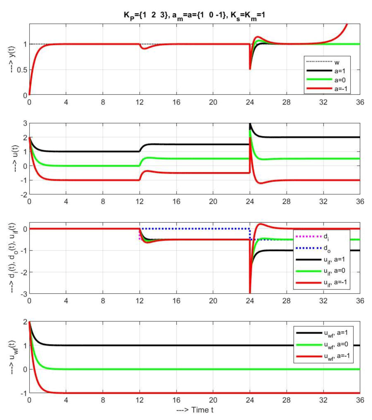
The first set of transient responses in Figure 4 with a = { 1 , 0 , 1 } and the nominal tuning a ¯ = a and K ¯ s = K s = 1 exhibits, with a = 1 in longer time horizon, despite stable disturbance response, instability.
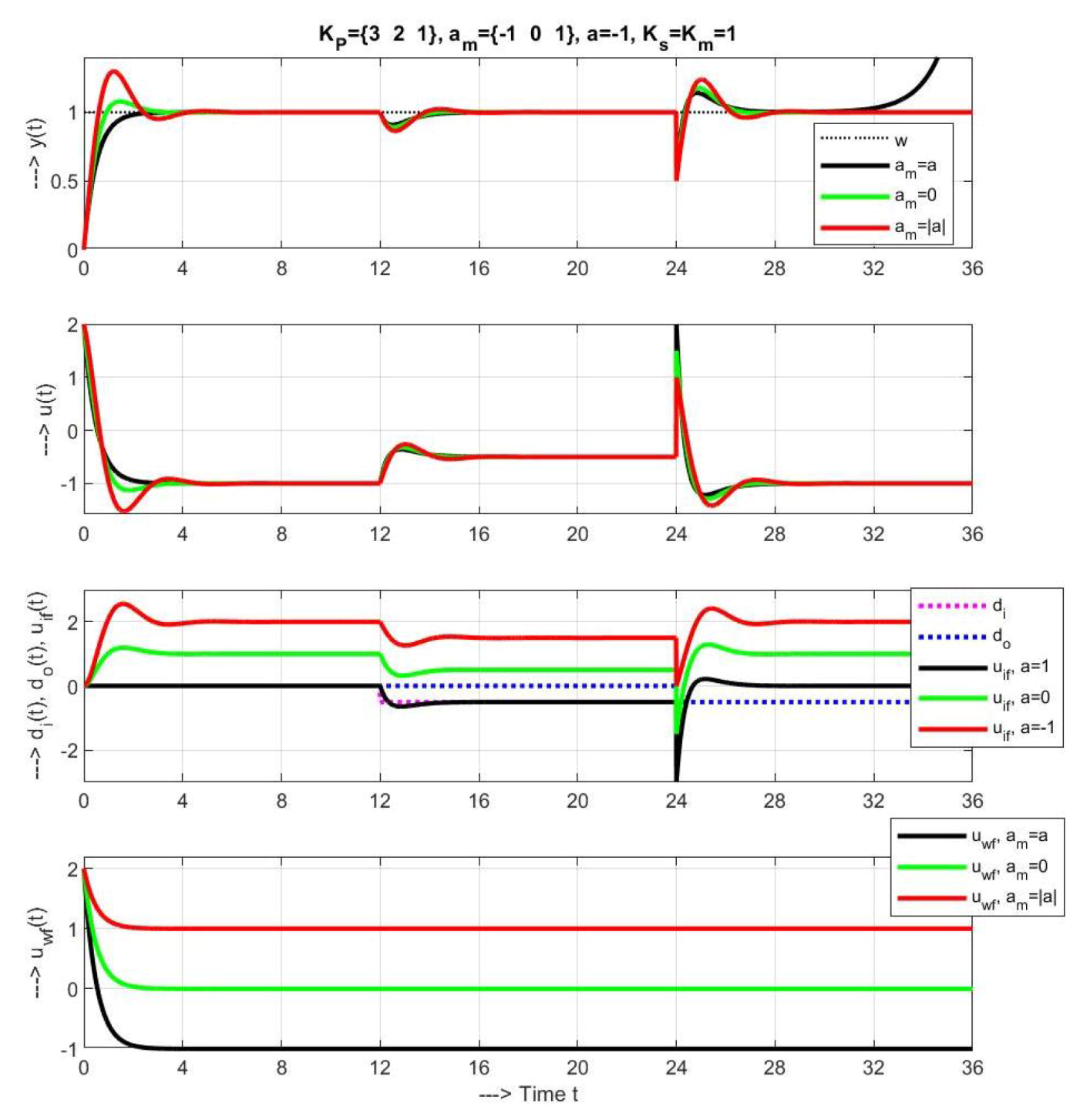
The second set of responses in Figure 5 corresponds to an unstable system with a = 1 , K ¯ s = K s = 1 and set of models characterized with a ¯ = { 1 , 0 , 1 } . Although, intuitively, one would expect as the optimal choice a ¯ = a , really stable solutions, although deformed in shape, can only be obtained by choosing a ¯ > 0 .

3.3. Explanation of Stability Problems

The above examples lead to seemingly contradictory results when the loop with an unstable system and a stable disturbance response F i y (which is crucial for stabilization of the unstable systems, but with an unstable model considered in DOB design, shows instability. One possible explanation for the problem would be to point out that the cancellation of the unstable pole of the disturbance response was achieved by an unstable transfer function F u (15), which is generally unacceptable. Another explanation may be found in the work by Schrijver and Dijk [15]. In order to fully expose the nature of the problem and avoid more complex time-delayed systems, we preferred to explain the phenomenon by using the simplest first-order systems. Before that, however, we recall the difference between the poles and modes of the system.
Definition 2 (Poles and Modes).
For a system given by the transfer function G ( s ) = B ( s ) / A ( s ) , where A ( s ) and B ( s ) are polynomials which may have common factors, i.e., some zeros of the polynomial equation A ( s ) = 0 may be common with zeros of B ( s ) = 0 , the zeros of A ( s ) will be denoted as modes. In the case where the both polynomials have no common factor (they are coprime), the set of zeros of A ( s ) will be denoted as poles.
Theorem 1 (Instability of loop with SDOB and decoupled dynamics).
For the unstable plant (1) and unstable model (2), the loop with SDOB from Figure 3 must be unstable.
Proof. 
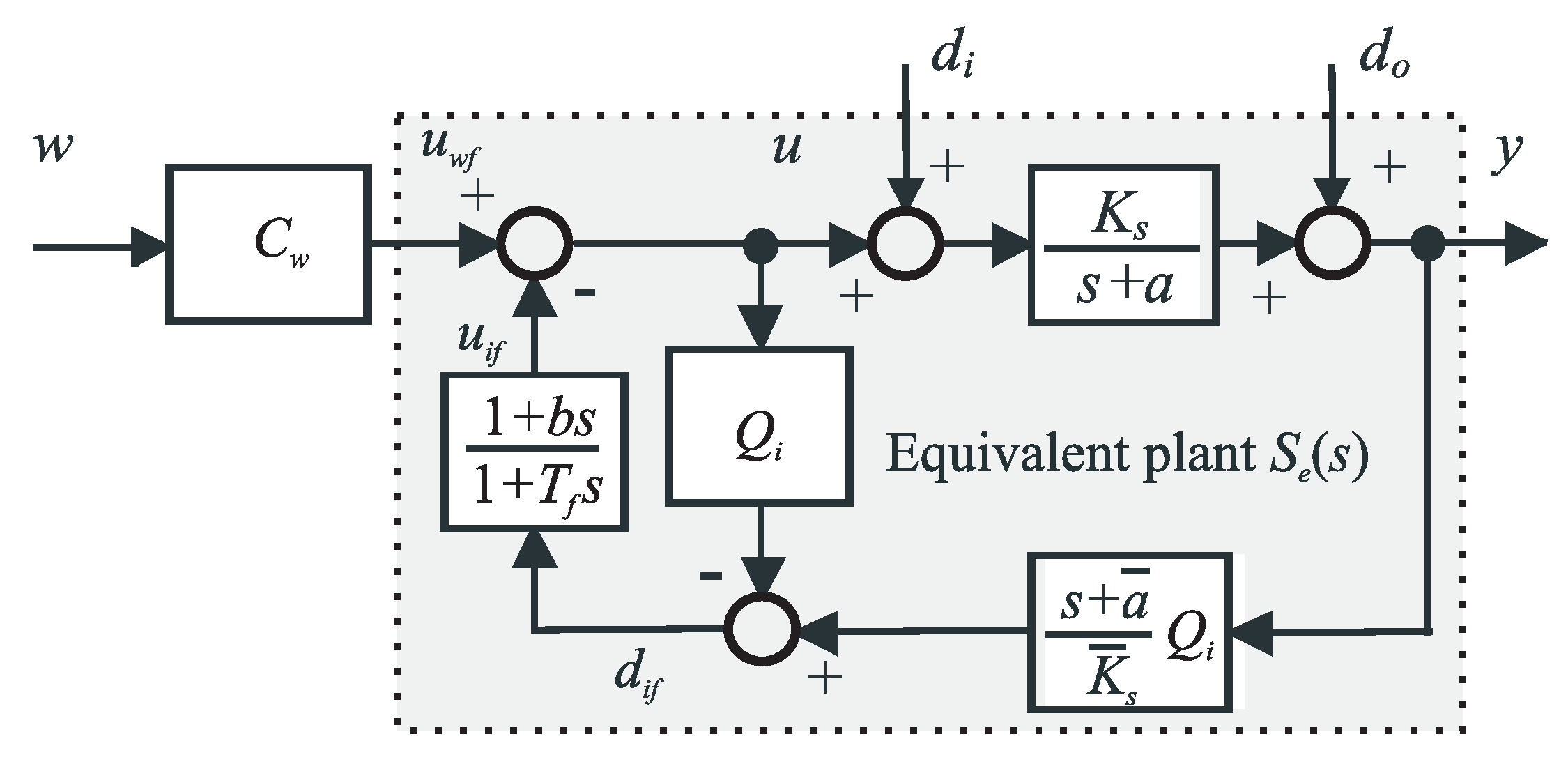
Despite the added feedback, the structure of Figure 3 can be still interpreted as a serial combination of the feedforward control with an equivalent plant S e ( s ) :
S e ( s ) = Y ( s ) U w f ( s ) = S ( s ) S ¯ ( s ) S ¯ ( s ) ( 1 Q d ( s ) ) + S ( s ) Q d ( s ) .
This can only be used for a stable S e ( s ) system. Thereby, the loop disturbance response is
F i y ( s ) = Y ( s ) D i ( s ) = S ( s ) S ¯ ( s ) ( 1 Q d ( s ) ) S ¯ ( s ) ( 1 Q d ( s ) ) + S ( s ) Q d ( s ) .
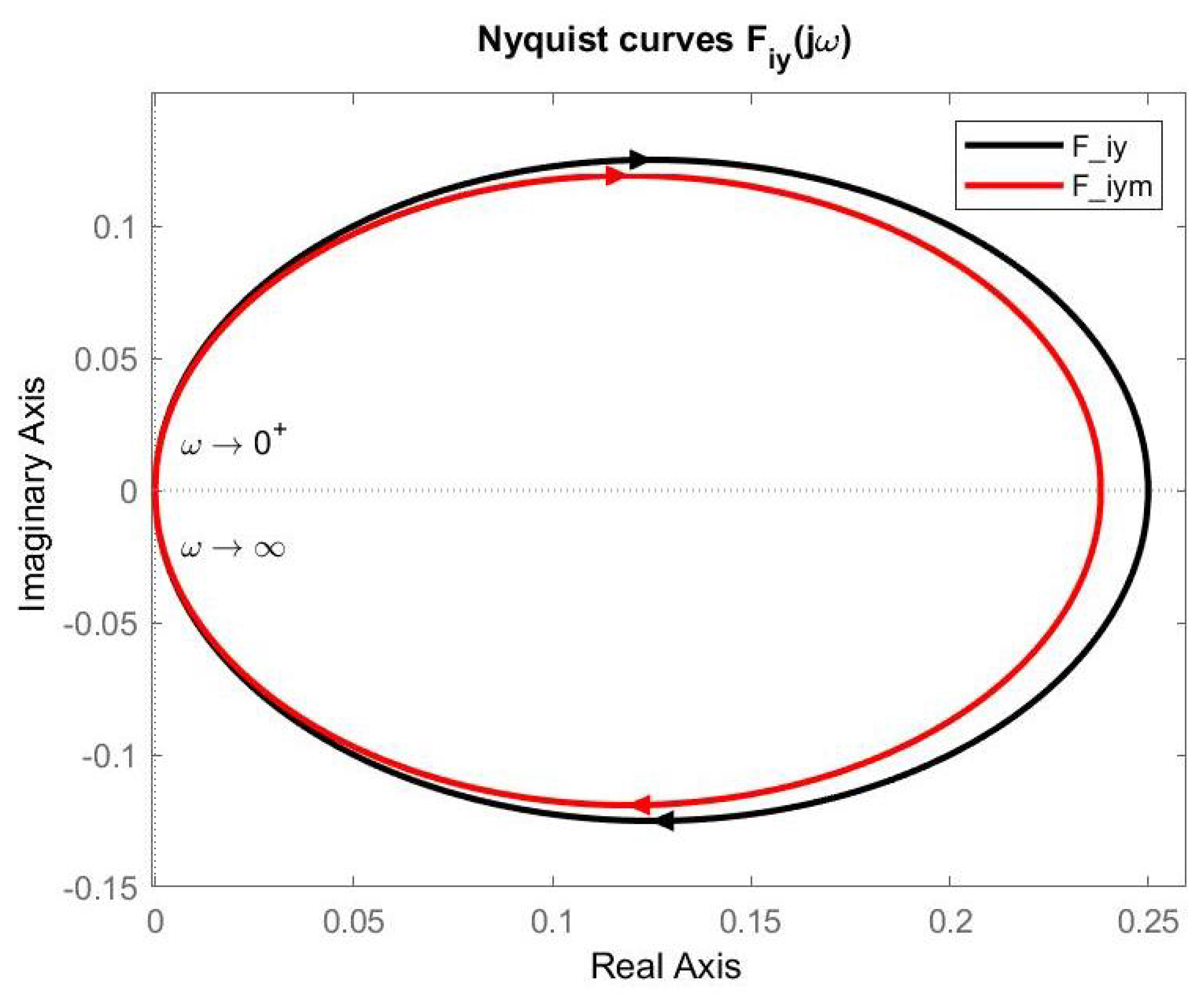
In low-frequency region (when s 0 ), Q d ( s ) 1 and F i y ( s ) 0 (Figure 6). It means that input disturbances (critical for unstable plants) are fully eliminated. Furthermore, also S e ( s ) S ¯ (Figure 7). Hence, the feedforward C w ( s ) designed for the model S ¯ , cancels the unstable plant pole and, thus, it should yield a precise setpoint tracking. Note, however, that this open-loop combination of the feedforward C w ( s ) with unstable S e ( s ) may not guarantee a stable equilibrium point y ( t ) = w ( t ) , since already negligible imperfection (see Lemma 1) may activate the unstable plant mode and lead to an output brake out.
Such imperfections arise already in middle- and high-frequency region (when s ) where Q d ( s ) 0 . Then, both F i y ( s ) S and S e ( s ) S . Since now S e ( s ) S ¯ ( s ) , the feedforward C w ( s ) does not act perfectly and eliminate the unstable plant pole. F i y ( s ) 0 indicates not perfect elimination of disturbances. All this may accelerate “explosion” of the unstable mode of the plant S ( s ) , so its output will diverge. □
To summarize, by enforcing the dynamics specified by the model parameters K ¯ s and a ¯ , for unstable systems ( a ¯ < 0 ), the SDOB according to Figure 3 yields transients tending to “explode”. Hence, imposing unstable dynamics on the system through SDOB and, at the same time, spending a lot of space and energy with analyzing just the the disturbance response, represent an example of a pointlessly applied mathematics.

4. Setpoint and Disturbance Reference Model Control

Today, feedforward control design is usually a standard part of automatic control textbooks [19]. In connection with a stabilizing controller, the setpoint feedforward control methodology has already been extended to the control of unstable systems. The corresponding control structure, offering coordination of all components of control, is denoted as the reference model control (RMC). The design of feedforward control for disturbance rejection is also extensively studied. In the nominal case, the supervising controller guaranteeing the loop stability without being nominally involved in operation, will not be disrupting the setpoint and disturbance feedforwards. Its presence will ensure the overall loop stability, together with a high performance even in situations that have so far seemed to be problematic (especially when controlling unstable systems).
Definition 3 (Reference model (RM)).
The reference models provide to the stabilizing controller the expected nominal process output responses for tracking or for disturbance compensation. They are given by the output transfer functions corresponding to the considered input (as, for example, Q w = F w y (5) for the setpoint tracking and F i = F i y (21) for the disturbance rejection).
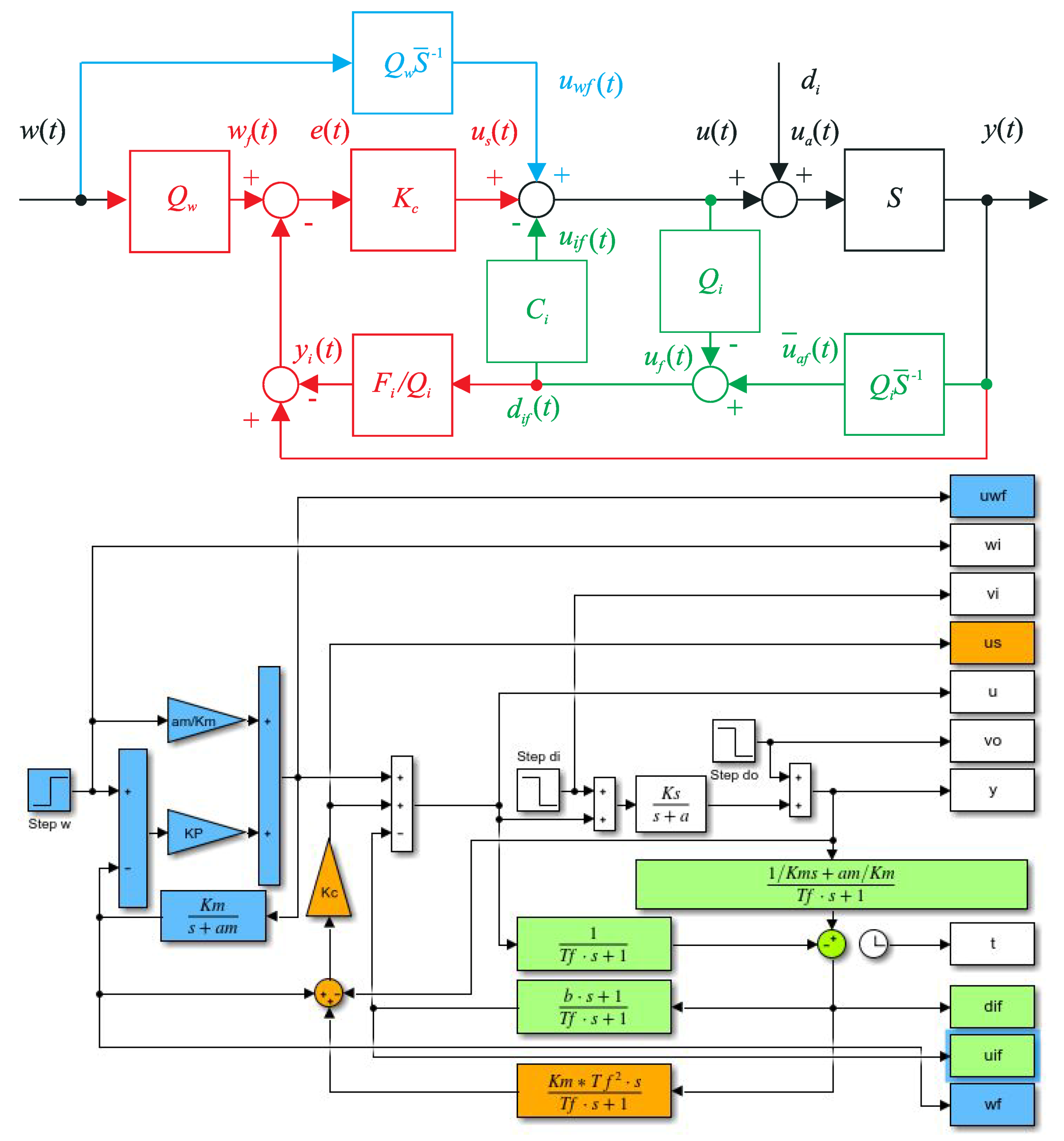
In the case of setpoint feedforward (blue blocks in Figure 8 above), in the nominal case, the process output response to setpoint changes is given by the transfer function of the low-pass filter Q w (3), or (7). When the output signal y coincides with the output of the reference model w f ( t ) , the difference between these variables is zero and the stabilizing controller K c is not active (i.e., u s ( t ) = 0 ).

4.1. Reference Model Control with Supervising Stabilizing Controller (Sdob-Rm)

Next we will return to the SDOB-RM control scheme in Figure 8, when by simply setting K c = K P (4), the stability condition (5) will be fulfilled. This setting activates both the R M from w and d i feedforwards denoted as R M w and R M i , respectively. The output signal of R M w is expressed by w f , whereas output of R M i is given by y i .
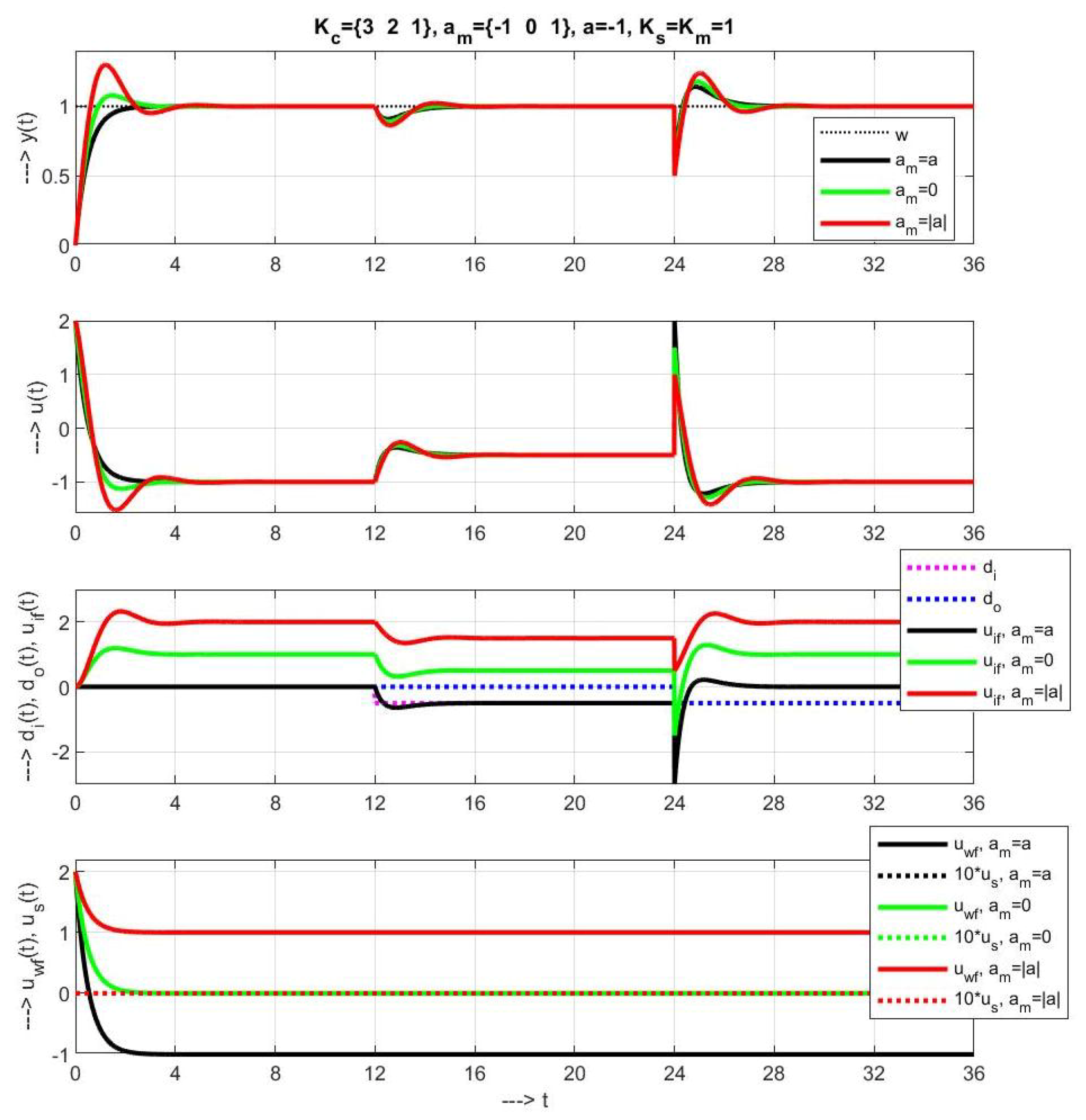
Transients on the unstable plant with a = 1 with different parameters a ¯ (Figure 9), used for calculating K c = ( 1 / T c a ¯ ) / K ¯ s , show similar performance as for the loop with SDOB responses in Figure 5. However, now they all remain stable for any t. Thereby, the equivalence with SDOB responses in Figure 5 can be observed from the output of the stabilizing controller u s 0 (see the lower figures).
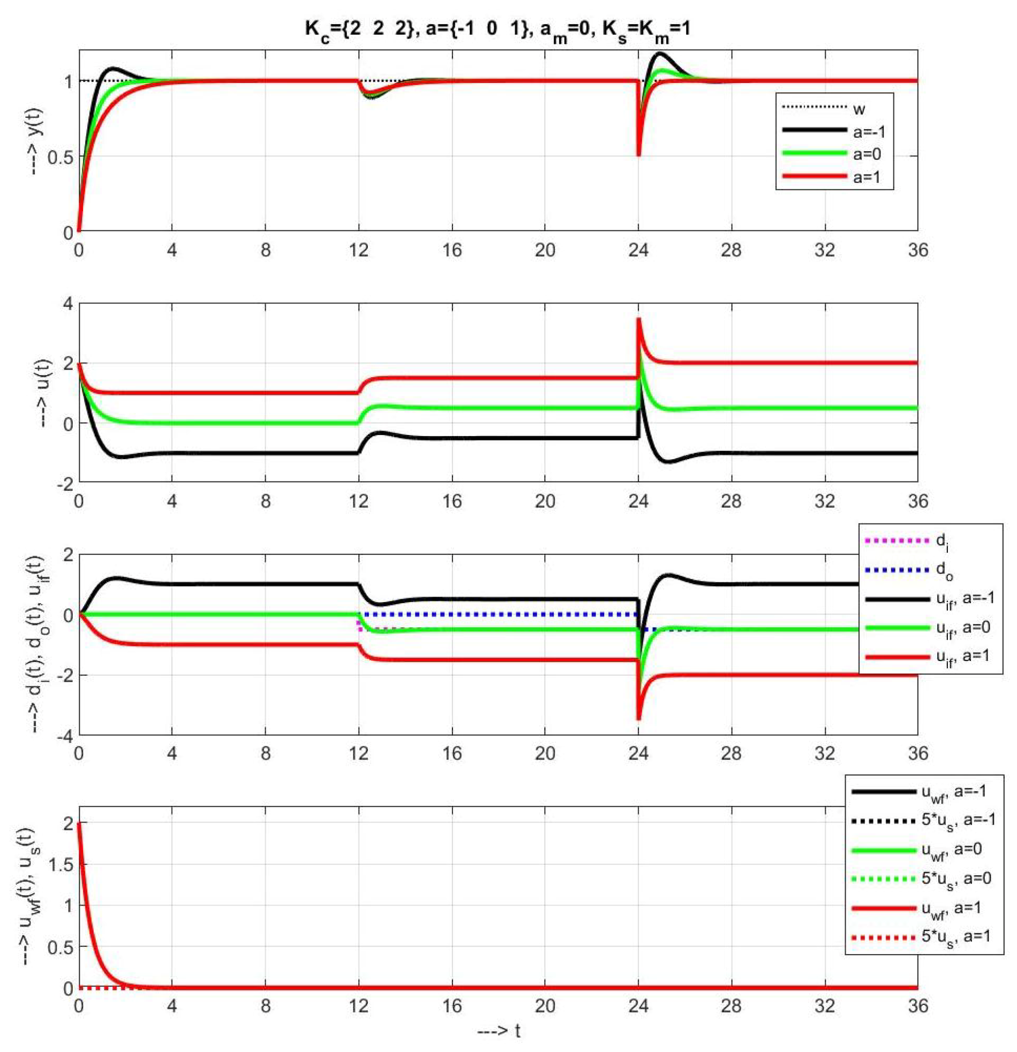
Figure 10 shows a relatively low dependence of transients from a ¯ for different a. This exhibits the specific role of integrating models in a simplified control of linear and possibly also nonlinear first-order plants. The inaccuracy of the model is reflected here in the reconstructed disturbance d i f (equal to u i f in steady states). It corresponds to the external disturbance just for a ¯ = a .

4.2. Constrained Control with Discussion of Some Modifications Proposed

We would like to remind you once more that we have also raised these SDOB issues in order to clarify a number of controversial situations in the articles on the control of time-delayed systems [8,9]. For example, in Reference [8], the authors give to the SDOB structure for an integral time-delayed system, without any explanation, comment “The original structure is not causal and sometimes is not internally stable”. And, based on it, they require implementation by a modified equivalent scheme.
We can now, step by step, verify all these requirements by solving a simplified task with a delay-free plant. By Theorem 1, we may explain the problems with stability. They required implementation by a modified equivalent scheme (see, e.g., Figure 1 in Reference [8]). In our terms, for the plant (1), by modifying Figure 3 with b (21), F u = ( ( 1 + T f s ) 2 / [ T f 2 s ( s + a ) ] (15) and after moving the term Q 1 / S into the feedforward path and the equivalent modifications, it is possible to get a PI-PD controller (Figure 11) with a direct acting PI controller
R s = Q i ( s ) S ¯ ( s ) ( 1 Q d ( s ) ) = 1 + T f s K ¯ s T f 2 s = K P I 1 + 1 T i s ; K P I = 1 K ¯ s T f ; T i = T f
combined with a feedback filtered PD compensator
F i s = Q d ( s ) Q i ( s ) = 1 + b s 1 + T f s
and a lead-lag prefilter
F s = Q w ( s ) Q i ( s ) = 1 + T f s 1 + T c s .
In deriving R ( s ) , the unstable model pole has been cancelled. Thus, it is not fully clear if the requirement expressed in Reference [8] by the formulation about “non-dynamical finite impulse response block avoiding possible pole-zero cancellations between controller and plant” has been appropriately respected, perhaps because there is no pole-zero cancellations between controller and plant. But, it is typical for the mentioned papers that such foggy formulations, which are essential for the correct understanding of the article, were not illustrated in details, for example, by a block diagram, or a Simulink scheme.
Other previously not mentioned problems may be illustrated with a simple example of constrained control considering u [ 1.1 , 0.5 ] .
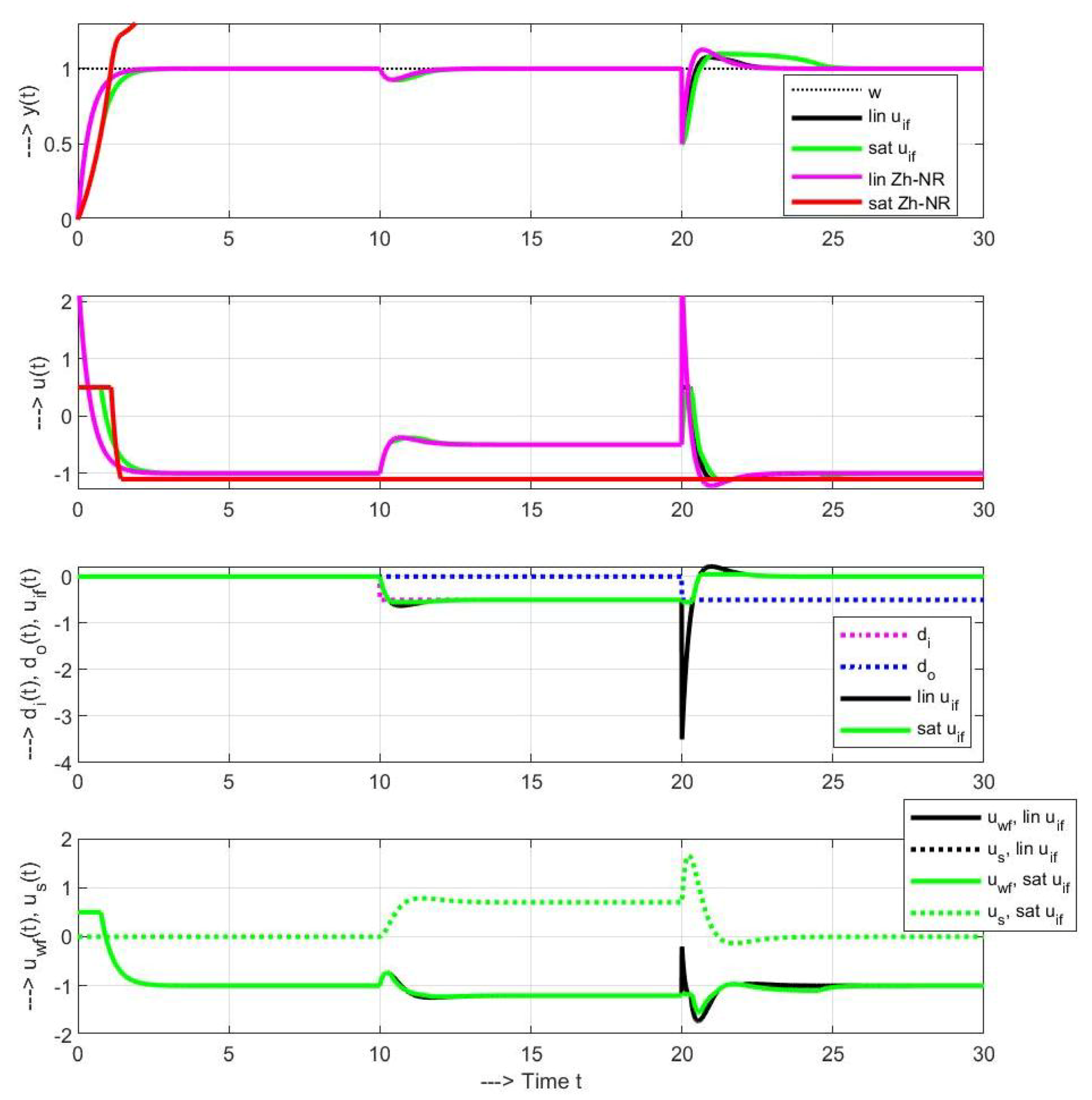
When designing constrained SDOB-RM control, there are several alternatives with different priorities of u w f , u i f and u s signals for total interventions exceeding the limits. Constrained SDOB-RM-based control, according to Figure 12 (right), is designed in Simulink by the dynamic saturation block so that the u s signal providing stabilization takes precedence when the total control action exceeds one of the constraints. In the corresponding transients in Figure 13 (in black), the limitation to U m a x = 0.5 appears at the beginning and than after the output disturbance step. The mixed feedforward signal u w f u i f then adapts to the given possibilities by unexpected peaks. The influence of the setpoint feedforward loop by non-zero signal u i f is compensated by the stabilizing signal u s .
When trying to eliminate high negative and positive peaks in u i f and u w f after the d o step by including another saturation block on the output u i f [ 0.55 , 0.05 ] , the limits of which are set so that they are effective only during these peaks (green course), the circuit responds with adequate course peaks of the stabilization signal u s . Although the peaks in the course of u w f disappear, the disturbance response at the plant output is slower.
Taking into account the priorities, according to Figure 12 (left), the u s and u i f signals would be similar to their transients in the linear circuit. However, high amplitudes of u s u i f would lead to changes in u w f .
Without saturation of u, the circuit with PI-PD controller according to Reference [8] works at the same settings as expected. However, with the controller output limited to u [ 1.1 , 0.5 ] , it is unstable.
Remark 3 (Do the SDOB modifications for unstable plants make sense?).
The DOB- and SDOB-based controllers were introduced to improve the dynamics provided by the PI(D) control. For unstable plants, measures were proposed to compensate for the stability problems that eventually led to the PI-PD controller. The problem was not solved but swept under the rug.
After the proposed modifications, it is no longer an SDOB-based control and the equivalent PI-PD controller will have all the shortcomings that inspired the emergence of DOB- and SDOB-based control.
Similarly, in Reference [9], except for loss of signal of the reconstructed disturbance, when using the equivalent structure from Figure 5b, the users will surely have problems with control constraints.
Skepticism above solutions for unstable systems can also be found in other authors [4], who preferred (similar to Reference [3]) their own approach to delay compensation based on the prediction of actual no-delayed output. However, these are no more directly related to the analyzed situation.
Hence, to summarize: New moment of the SDOB and SDOB-RM schemes is that both the setpoint and disturbance feedforward by inverse transfer function may also be applied in presence of (external and internal) disturbances, uncertainties, and control constraints. Then, these structures are easier to explain than for the stabilizing disturbance feedforward of the IMC-like control.
Remark 4 (Key asymmetry of SDOB-based structures for stable and unstable systems).
The primary difference in the approach to the control of stable and unstable systems by SDOB-based loops with decoupled dynamics according to Figure 3 is that, while in stable systems the highest performance achieved is tied to the highest possible matching between the controlled plant and its model, in unstable systems, the use of an unstable model inevitably leads to loop instability. Stability can be ensured by choosing a stable model but at the cost of high deviations of transients from their ideal shapes. While the excellent performance and stability of the loop with SDOB-based decoupled dynamics can be kept in the control of unstable systems by using stabilizing controller with reference models for the setpoint tracking and disturbance rejection, use of the stabilizing controller is unnecessary in the case of stable systems.
Remark 5 (Special role of integrating models).
Transients achieved with integral model a ¯ = 0 , which may be based on a significantly simpler plant identification, show acceptable loop performance for a broad class of first-order systems. This means that integrating models can be considered as more general “ultra-local” type of linear models broadly used within the model-free control [24], or in active disturbance rejection control (ADRC) [25]. An essential feature of their success can obviously be applied also in other methods of controller design.
While the use of FOTD models (with a ¯ 0 ) and IPDT models with a ¯ = 0 appears to differ only in the value of a single parameter, it has a huge impact on the organization of the necessary identification experiments.
Comparison of performance with controller based on FOTD and IPDT models can also be used as an indicator of their robustness: if the obtained results do not differ significantly, the controllers can be considered robust. If the differences are large, the sensitivity of the controllers to parameter changes will probably be high [6]. (A deeper analysis of these claims is beyond the scope of this article. However, readers interested in the issue can verify it experimentally with an interactive online application located on the site http://apps.iolab.sk/advanced/symmetry2020/.)

5. Generalization to Time Delayed Systems

After clarifying the basic problems arising in SDOB-based structures due to asymmetries in the control of stable and unstable first order systems, we can proceed to the more general problem of the first-order time delayed (FOTD) systems control with focus mainly on differences in controlling stable ( a > 0 ) and unstable FOTD (UFOTD) systems ( a < 0 ):
S s = Y ( s ) U ( s ) = K s e T d s s + a .
The FOTD model will now be factorized into the invertible and non-invertible parts S ¯ and S ¯ + (including the dead-time and possible unstable zeros) as
S ¯ s = S ¯ ( s ) S ¯ + ( s ) = K ¯ s e T ¯ d s s + a ¯ ; S ¯ ( s ) = K ¯ s s + a ¯ ; S ¯ + ( s ) = e T ¯ d s .
The basic changes in the simulation scheme in Figure 14, when compared to Figure 8, will be the inclusion of the transport delay in the controlled system, as well as in the reference models F w (given by the transfer function F w y ( s ) (29)), F i (equals to approximation (36) of F i y ( s ) ), and in the DOB branch S u d (31).

5.1. Setpoint and Disturbance Reference Models

Since the transport delay of the system must inevitably be reflected in the closed-loop transfer functions and it does not belong to the invertible terms, it has to be added to F w y . Thus, nominally
F w y ( s ) = Y ( s ) W ( s ) = e T d s T c s + 1 ; I A E w = T c + T d .
Accordingly, from (29), the setpoint reference model is derived as:
F w ( s ) = Q w ( s ) S ¯ + = e T ¯ d s T c s + 1 .
When implementing the setpoint feedforward blocks by a primary loop, between the output of the system model S ¯ and the input of the stabilizing controller, the delay part T m of the model ( S ¯ + ) has to be added (Figure 14 below).
The disturbance reconstruction and compensation will be derived according to Equation (14) and taking into account the relation U i f ( s ) = S y d ( s ) Y ( s ) S u d ( s ) U ( s ) with:
S u d ( s ) = Q d ( s ) S ¯ + = 1 + b s ( 1 + T f s ) 2 e T ¯ d s ,
S y d ( s ) = Q d ( s ) S ¯ 1 = ( s + a ¯ ) ( 1 + b s ) K s ( T f s + 1 ) 2 .
The basis for deriving the disturbance reference model F i is again the disturbance response transfer function F i y ( s ) . After including the delayed model into the observer’s branch from the output of the controller, when S u d = Q d ( s ) e T ¯ d s , in the nominal case with T ¯ d = T d the disturbance response will be given, according to (15), as
F i y ( s ) = Y ( s ) D i ( s ) = S 1 + F u S y d S ; S = K s e T d s s + a ; F u = 1 1 S u d .
After some modification, in the nominal case
F i y ( s ) = [ ( 1 + T f s ) 2 ( 1 + b s ) e T d s ] K s e T d s ( s + a ) ( 1 + T f s ) 2 .
The parameter b will again be determined to cancel the the possibly unstable plant pole ( s + a ) by the numerator zero. It may be derived from N F i y ( a ) = 0 as
b = 1 a 1 ( 1 a T f ) 2 e a T d .
In the case of stable systems it is possible to work with F i ( s ) = F i y ( s ) (34). With respect to stability, it is, however, not allowed for a < 0 , when the unstable pole and zero have to be cancelled. Given the transcendent character of the numerator quasi-polynomial, the reduced transfer function corresponding to the canceling of the terms ( s + a ) is only approximated. Since it also holds F i y ( 0 ) = 0 , the reduced disturbance response may be approximated by the transfer function
F i ( s ) = K s h 1 s e T d s ( 1 + T f s ) 2 .
By comparing (36) with (34), it follows:
[ ( 1 + T f s ) 2 ( 1 + b s ) e T d s ] = h 1 s ( s + a ) .
By differentiating (37) according to s and substituting s = 0 , we get
h 1 = 1 a ( 2 T f b + T d ) ,
which specifies the reduced disturbance response transfer function and reference model (36). The corresponding I A E i value is
I A E i = K s a 2 2 a T f ( 1 e a t d ) + a T d + ( 1 + a 2 T f 2 ) e a t d .
In the limit a 0 for integral models we get
b = 2 T f + T d ; h 1 = 4 T f T d + 2 T f 2 + T d 2 I A E i = K s 2 T d 2 + 2 T f ( 2 T d + T f ) .
Thus, for T f 0 , the I A E i becomes K s T d 2 / 2 .

5.2. Proportional Gains for FOTD Systems

Note that the controller gains, when controlling UFOTD systems, are now not only limited from the bottom side (5) but also from above. The appropriate controller gain can be calculated so as to achieve the double real dominant pole in the reference closed-loop model, for which the transients are the fastest ones but not yet oscillating. Here, we start from the characteristic quasi-polynomial of the loop with the gain K c and the FOTD system:
A ( s ) = ( s + a ) e T d s + K s K c
By selecting a double real dominant pole s o satisfying equations
A ( s ) ; d d s A ( s ) s = s o = 0 ,
the first derivative in (42) yields:
d d s A ( s ) = e T d s + ( s + a ) T d e T d s = 0 .
From (43), we get
s o = ( 1 + a T d ) / T d ; T o = 1 / s o = T d / ( 1 + a T d ) .
The “optimal” controller gain and the admissible dead-time follow from s o < 0 as
K c o = e 1 a T d K s T d ; a T d > 1 .
The same P controller gain may then be used as a limit value of K P also in the setpoint feedforward loop.
Remark 6
(Differences in the K c gains derived by FOTD and IPDT models). As already discussed in Remark 5, by comparing results achieved with FOTD and IPDT approximations we may get information about the loop robustness. In this way, it is possible to find out that the controller gain K c o does not significantly depend on a ¯ for a T d 0 , whereas, for a T d 1 , the differences corresponding to a ¯ = 0 and a ¯ = a will be significant. It is possible to experimentally verify that, in the first case, the loop will be robust by using both controllers, whereas, in the second case, the simple tuning a ¯ = 0 does not guarantee stability, and the nominal controller is very sensitive to perturbations.
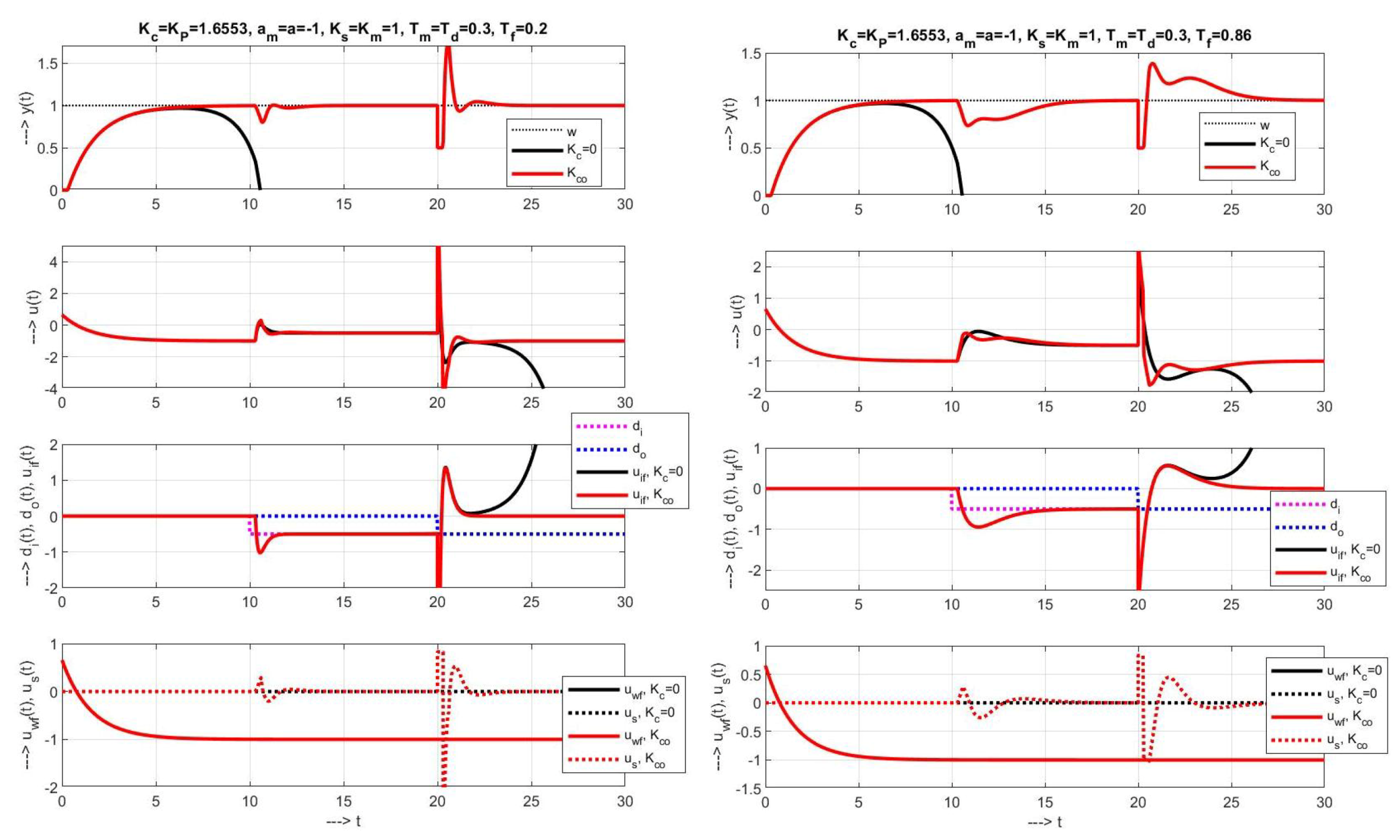
Transients in Figure 15 left correspond to the SDOB-RM-based control of UFOTD plant (27) and (28) according to Figure 14, with nominal parameters a ¯ = a = 1 , K ¯ s = K s = 1 , T ¯ d = T d = 0.3 , T f = 0.2 (in the figures, the variables a ¯ , T ¯ d and K ¯ s are denoted as a m , T m and K m ). When choosing the primary loop controller gain K P = K c (45), the setpoint reference model (30) corresponds to the time constant T c = 1 / ( K s K P + a ¯ ) = 1.53 , which is about four times the “dominant” time constant given by the stabilizing controller design T o = 1 / s o = 0.43 . With respect to these results, the first chosen value T f = 0.2 is much lower. When related to the average residence time 2 T o calculated from the time constant corresponding to the double dominant pole, the filter time would be T f = 2 T o = 0.86 (Figure 15 right), and the transients would be slower. The maximum amplitudes, due to process input step disturbances, would increase and, due to process output step disturbances, would decrease. However, on the other hand, the shapes of the transients did not change significantly, which provides a sufficiently wide space for selecting a suitable T f value. As assumed, the responses corresponding to the switched off stabilizing controller ( K c = 0 ), diverge. Due to approximate character of F i , the u s response is not ideally zero.
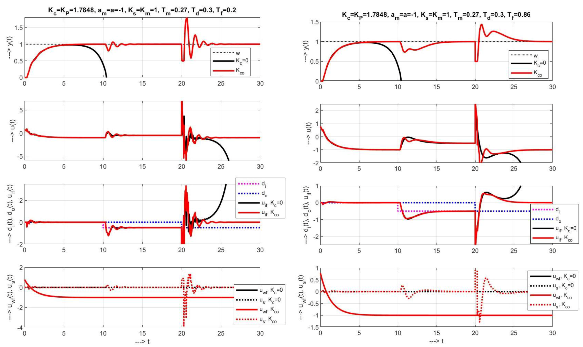
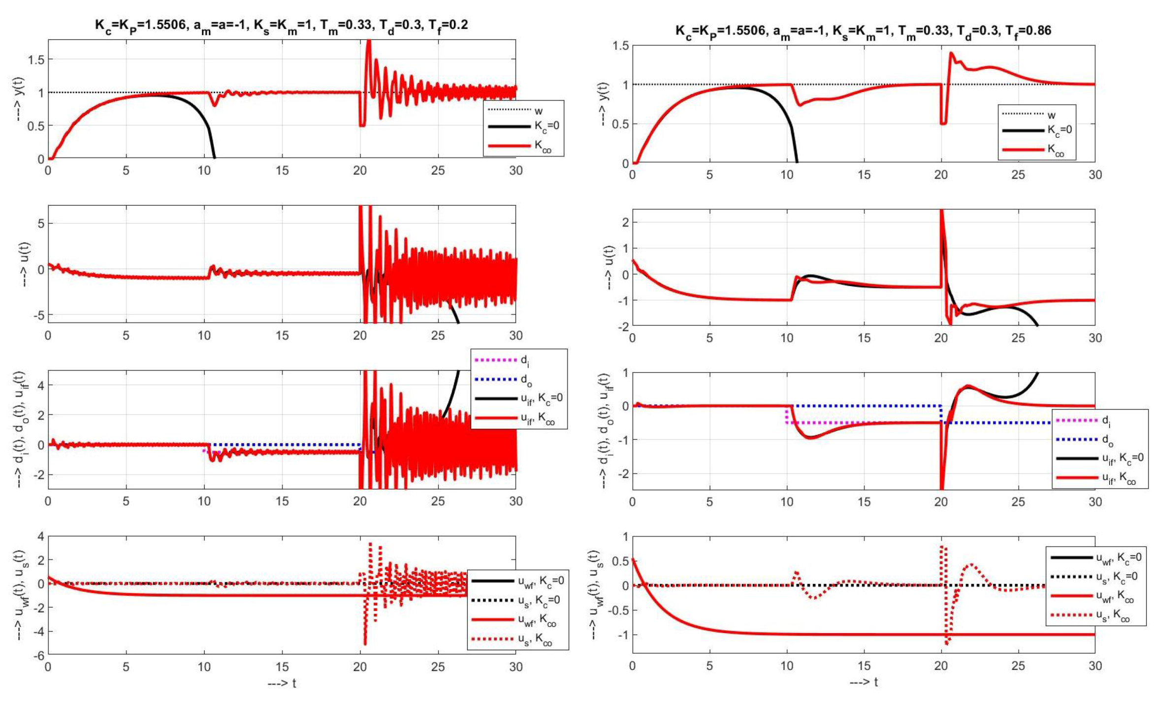
The robustness of the controller with different values of filter time constant T f was tested on ± 10 % change of model time delay (Figure 16 and Figure 17).
All these processes confirm the attractiveness of the obtained controllers for practical applications, while their advantage is the observance of the original structure with reconstruction and disturbance compensation, which will guarantee good transient properties even with a possible limitation of the control action variable.
The robustness of transients and especially the influence of measurement noise can also be influenced by increasing the filter order of the PD controller C i .

6. Conclusions and Future Work

The article showed that the simplification, achieved by omitting transport delays from the frequently considered processes, helped also in the control of unstable time-delayed first-order systems. The misinterpretation of the differences between the conceptual DOB-based scheme and the implementation scheme [8,9] have resulted into several misleading approaches in the last decades and silenced key features of the structures used. Namely, in addition to the necessary stability condition of the disturbance response, the overall stability of the circuit was neglected. The stability of the closed-loop control of unstable systems, with the decoupled setpoint and disturbance feedforward cannot be achieved using unstable nominal models (which would be useful from the point of view of achieving ideal transient responses). The carried-out analysis also revealed that the solutions, proposed in some references [8,9], lead to loops with traditional PI control combined with a feedback PD controller. Since the DOB-based controllers have been proposed with the aim of improving the dynamics of the traditional PI control, such modifications do not meet the design goals and therefore do not represent any added value.
As the novel contribution, it has been shown that maintaining the ideal closed-loop responses is possible only by supplementing the circuit with a stabilizing controller. This, in order not to modify the ideal transients of the setpoint and disturbance feedforward sub-circuits, must be supplemented by the reference models. The work also revealed several reasons for the implementation of the setpoint feedforward by a primary loop, in which it is sufficient to work with a 2DOF P control instead of the traditionally used PI control. It is interesting to note that, according to the best of our knowledge, the available references do not mention the role of constraints, which are crucial in practice.
Although the disturbance reference model for UFOTD systems is only approximately derived, the verification by simulation shows very good transients in both nominal and perturbed cases and the possibility of simple circuit tuning in a wide range of process dynamics variations. Further work here will focus on improving it with solutions proposed in the discrete-time domain.
Another possible solution would be to firstly stabilize the plant by a local feedback with, e.g., the P controller, and then apply some of the disturbance reconstruction and compensation methods.
Similar problems have yet to be solved in case of compensation schemes formulated for output disturbances, as, for example, the filtered Smith predictor.
All the relevant structures can be found in an interactive online form on the site http://apps.iolab.sk/advanced/symmetry2020/. This makes it easy to verify the proposed structures with arbitrary parameter values and compare them with other already published solutions.

Author Contributions

Writing-original draft preparation, M.H. Simulations, P.B. and M.H. Editing, D.V., P.B., and M.H. Web application, K.Z. and M.H. Project administration, P.B. All authors have read and agreed to the published version of the manuscript.

Funding

This research was funded by the grants APVV SK-IL-RD-18-0008 Platoon Modeling and Control for mixed autonomous and conventional vehicles: a laboratory experimental analysis, VEGA 1/0745/19 Control and modeling of mechatronic systems in emobility and within research program P2-0001, financed by the Slovenian Research Agency.

Acknowledgments

Supported by E-Academia Slovaca, non-profit organization, Sadmelijská 1, 831 06 Bratislava, Slovakia.

Conflicts of Interest

The authors declare no conflict of interest.

Abbreviations

The following abbreviations are used in this manuscript:
2DOF2 Degree of Freedom
DOBDisturbance observer
FOTDFirst Order Time Delayed
FSPFiltered Smith Predictor
IMCInternal model control
PProportional
PIProportional-Integrative
PDProportional-Derivative
PIDProportional-Integrative-Derivative
RMReference model
RMCReference model control
SDOBStabilizing disturbance observer
SPSmith Predictor
UFOTDUnstable First Order Time Delayed

References

  1. O’Dwyer, A. Handbook of PI and PID Controller Tuning Rules, 3rd ed.; Imperial College Press: London, UK, 2009. [Google Scholar]
  2. Smith, O. Closser control of loops with dead time. Chem. Eng. Prog. 1957, 53, 217–219. [Google Scholar]
  3. Huba, M.; Kul’ha, P.; Žákova, K. Observer-Based Control of Unstable Process with Dead Time. In Proceedings of the 10th Conference Process Control’95, Tatranské Matliare, Slovakia, 4–7 June 1995; Volume 1, pp. 35–38. [Google Scholar]
  4. Garcia, P.; Albertos, P. A new dead-time compensator to control stable and integrating processes with long dead-time. Automatica 2008, 44, 1062–1071. [Google Scholar] [CrossRef]
  5. Sanz, R.; García, P.; Albertos, P. A generalized smith predictor for unstable time-delay SISO systems. ISA Trans. 2018, 72, 197–204. [Google Scholar] [CrossRef] [PubMed] [Green Version]
  6. Huba, M.; Bélai, I. Limits of a Simplified Controller Design Based on IPDT models. Proc. Inst. Mech. Eng. Part I J. Syst. Control Eng. 2018, 232, 728–741. [Google Scholar]
  7. Huba, M. Improving noise attenuation in modified filtered Smith predictor. In Proceedings of the 2020 Cybernetics and Informatics (KandI), Velke Karlovice, Czech Republic, 29 January–2 February 2020. [Google Scholar]
  8. Zhong, Q.; Normey-Rico, J. Control of integral processes with dead-time. Part 1: Disturbance observer-based 2DOF control scheme. IEE Proc. Control Theory Appl. 2002, 149, 285–290. [Google Scholar] [CrossRef] [Green Version]
  9. Normey-Rico, J.; Camacho, E. Dead-time compensators: A survey. Control. Eng. Pract. 2008, 16, 407–428. [Google Scholar] [CrossRef]
  10. Normey-Rico, J.; Camacho, E. Unified approach for robust dead-time compensator design. J. Process Control 2009, 19, 38–47. [Google Scholar]
  11. Vrečko, D.; Vrančič, D.; Jurčič, D.; Strmčnik, S. A new modified Smith predictor: The concept, design and tuning. ISA Trans. 2001, 40, 111–121. [Google Scholar] [CrossRef]
  12. Torrico, B.C.; Cavalcante, M.U.; Braga, A.P.S.; Normey-Rico, J.E.; Albuquerque, A.A.M. Simple Tuning Rules for Dead-Time Compensation of Stable, Integrative, and Unstable First-Order Dead-Time Processes. Ind. Eng. Chem. Res. 2013, 52, 11646–11654. [Google Scholar] [CrossRef]
  13. Rossiter, A.; Serbezov, A.; Visioli, A.; Žáková, K.; Huba, M. A survey of international views on a first course in systems and control for engineering undergraduates. IFAC J. Syst. Control 2020, 13, 100092. [Google Scholar] [CrossRef]
  14. Skogestad, S. Simple analytic rules for model reduction and PID controller tuning. J. Process Control 2003, 13, 291–309. [Google Scholar]
  15. Schrijver, E.; van Dijk, J. Disturbance Observers for Rigid Mechanical Systems: Equivalence, Stability, and Design. ASME J. Dyn. Syst. Meas. Control 2002, 124, 539–548. [Google Scholar] [CrossRef] [Green Version]
  16. Morari, M.; Zafiriou, E. Robust Process Control; Prentice Hall: Englewood Cliffs, NJ, USA, 1989. [Google Scholar]
  17. Grimholt, C.; Skogestad, S. Optimal PI and PID control of first-order plus delay processes and evaluation of the original and improved SIMC rules. J. Process Control 2018, 70, 36–46. [Google Scholar] [CrossRef]
  18. Abe, N.; Yamanaka, K. Smith predictor control and internal model control—A tutorial. In Proceedings of the SICE 2003 Annual Conference (IEEE Cat. No.03TH8734), Fukui, Japan, 4–6 August 2003; Volume 2, pp. 1383–1387. [Google Scholar]
  19. Visioli, A. Practical PID Control; Springer: London, UK, 2006. [Google Scholar]
  20. Ohishi, K. A new servo method in mechantronics. Trans. Jpn. Soc. Elect. Eng. 1987, 107-D, 83–86. [Google Scholar]
  21. Chen, W.H.; Yang, J.; Guo, L.; Li, S. Disturbance-Observer-Based Control and Related Methods—An Overview. IEEE Trans. Ind. Electron. 2016, 63, 1083–1095. [Google Scholar] [CrossRef] [Green Version]
  22. Peng, Y.; Vrančič, D.; Hanus, R. Anti-Windup, Bumpless and Conditioned Trnasfer Techniques for PID Controllers. IEEE Control Syst. 1996, 16, 48–57. [Google Scholar]
  23. Hong, K.; Nam, K. A load torque compensation scheme under the speed measurement delay. IEEE Trans. Ind. Electron. 1998, 45, 283–290. [Google Scholar] [CrossRef]
  24. Fliess, M.; Join, C. Stability margins and model-free control: A first look. In Proceedings of the 2014 European Control Conference (ECC), Strasbourg, France, 24–27 June 2014; pp. 454–459. [Google Scholar]
  25. Gao, Z. On the centrality of disturbance rejection in automatic control. ISA Trans. 2014, 53, 850–857. [Google Scholar] [CrossRef] [PubMed] [Green Version]
Figure 1. Application of two-degrees-of-freedom (2DOF) P control in plant stabilization (a) and setpoint feedforward (b); d i and d o —input and output disturbances.
Symmetry 12 01595 g001
Figure 2. Open loop (transfer function-based) and closed loop 2DOF P control-based constrained setpoint feedforward implementations with a unit setpoint step of w; K P = ( 1 / T c a ¯ ) / K ¯ s , a ¯ = a = 0 , K ¯ s = K s = 1 , T c = 0.5 , U m a x = 0.2 , U m i n = 0 ; in the Simulink scheme, the parameters a ¯ and K ¯ s are denoted as a m and K m .
Symmetry 12 01595 g002
Figure 3. Decoupled setpoint feedforward C w ( s ) and stabilizing disturbance observer (SDOB)-based disturbance feedforward Q d ( s ) = C i ( s ) Q i ( s ) (12) (drawn with n = 1 ) and the equivalent plant S e ( s ) .
Symmetry 12 01595 g003
Figure 4. Transients with SDOB for different a ¯ = a with an d i step at t m a x / 3 and an d o step at 2 t m a x / 3 : The instability of the system with a ¯ = a < 0 with input and output disturbances will manifest itself over time (in legend a ¯ = a m and K ¯ s = K m ); T c = T f = 0.5 .
Symmetry 12 01595 g004
Figure 5. For unstable systems, it is not possible to choose a ¯ < 0 due to internal instability (in legend, a ¯ = a m and K ¯ s = K m ).
Symmetry 12 01595 g005
Figure 6. Nyquist curves of the disturbance response transfer function F i y ( j ω ) corresponding to a nominal SDOB with a ¯ = a = 1 and to a perturbed system with F i y m ( j ω ) corresponding to a ¯ = 1.2 , K s = K ¯ s = 1 , T f = 0.5 ; b = T f ( 2 a ¯ T f ) .
Symmetry 12 01595 g006
Figure 7. Nyquist curve of the equivalent plant S e ( j ω ) approaches for ω 0 S ¯ ( j ω ) and for ω S ( j ω ) ; a = 1 , a ¯ = 1.2 , K s = K ¯ s = 1 , T c = T f = 0.5 ; b = T f ( 2 a ¯ T f ) (in legend S ¯ = S m ).
Symmetry 12 01595 g007
Figure 8. Setpoint feedforward with reference model (blue) and SDOB-based disturbance feedforward (green) and stabilizing controller K c with reference model Q w = F w y from the setpoint w and F i = F i y from the disturbance d i (red); the above is the block diagram with setpoint feedforward based on transfer function and below is the Simulink scheme with setpoint feedforward based on primary loop with K P = ( 1 / T f a ¯ ) / K ¯ s ; in the Simulink scheme, the variables a ¯ and K ¯ s are denoted as a m and K m .
Symmetry 12 01595 g008
Figure 9. “Always” stable transients of reference model control according to Figure 8 with stabilizing controller K c = K P = ( 1 / T c a ¯ ) / K ¯ s , for three different model parameters a ¯ = { 1 , 0 , 1 } and reference models from w and d i as a modification of transients in Figure 5, T c = T f = 0.5 , a = 1 , K ¯ s = K s = 1 .
Symmetry 12 01595 g009
Figure 10. Transients with reference model control according to Figure 8, with fixed setting a ¯ = 0 for different a K c = K P = ( 1 / T c a ¯ ) / K ¯ s , T c = T f = 0.5 ; in MATLAB/Simulink, the variables a ¯ and K ¯ s are denoted as a m and K m .
Symmetry 12 01595 g010
Figure 11. Constrained filtered Proportional-Integrative (PI) control based on modification proposed by Reference [8].
Symmetry 12 01595 g011
Figure 12. Implementation of control signal constraints with higher priority of the u s u i f signal (left) and in MATLAB/Simulink with higher priority of u s (right); thereby, the variables a ¯ and K ¯ s are denoted as a m and K m .
Symmetry 12 01595 g012
Figure 13. Transients with constrained SDOB-Reference model (RM)-based control according to Figure 12 with unconstrained and constrained signal u i f [ 0.55 , 0.05 ] and constrained filtered PI-Proportional-Derivative (PD) control according to Figure 11 based on modification proposed by Reference [8]; u [ 1.1 , 0.5 ] ; a ¯ = a = 1 ; K ¯ s = K s = 1 ; T c = T f = 0.4 .
Symmetry 12 01595 g013
Figure 14. Setpoint feedforward with reference model (blue) and SDOB-based disturbance feedforward (green) and stabilizing controller K c with reference models from the setpoint w and disturbance d i (red) for first-order time-delayed (FOTD) plant (27) and (28); block diagram with setpoint feedforward based on transfer function (above) and the Simulink scheme with setpoint feedforward based on primary loop with the gain K P (below); in the Simulink scheme, the variables a ¯ , T ¯ d and K ¯ s are denoted as a m , T m and K m .
Symmetry 12 01595 g014
Figure 15. Transients with reference model control of unstable FOTD (UFOTD) plant (27) and (28) according to Figure 14, with nominal parameters a ¯ = a = 1 , K ¯ s = K s = 1 , T ¯ d = T d = 0.3 , T f = 0.2 (left) and T f = 0.86 (right).
Symmetry 12 01595 g015
Figure 16. Transients with reference model control of UFOTD plant (27) and (28) according to Figure 14, with parameters a ¯ = a = 1 , K ¯ s = K s = 1 , T ¯ d = 0.9 T d , T d = 0.3 , T f = 0.2 (left) and T f = 0.86 (right).
Symmetry 12 01595 g016
Figure 17. Transients with reference model control of UFOTD plant (27) and (28) according to Figure 14, with parameters a ¯ = a = 1 , K ¯ s = K s = 1 , T ¯ d = 1.1 T d , T d = 0.3 , T f = 0.2 (left) and T f = 0.86 (right).
Symmetry 12 01595 g017