Article

Optimization of Energetic Train Cooperation

1
Department of Rail Transportation and Bridges, Faculty of Civil and Environmental Engineering, Gdańsk University of Technology, 80-233 Gdańsk, Poland
2
Division of Construction Fundamentals of Transport Equipment, Faculty of Transport, Warsaw University of Technology, 00-661 Warszawa, Poland
3
Division of Transportation Systems Engineering and Logistics, Faculty of Transport, Warsaw University of Technology, 00-661 Warszawa, Poland
*
Author to whom correspondence should be addressed.
Symmetry 2019, 11(9), 1175; https://doi.org/10.3390/sym11091175
Submission received: 12 July 2019 / Revised: 21 August 2019 / Accepted: 14 September 2019 / Published: 16 September 2019

Abstract

:
In the article, possible ways of using energy recovered during regenerative braking of trains are presented. It is pointed out that the return of recovered electricity directly to the catenary and its use in the energy cooperation of vehicles can be a no-cost method (without additional infrastructure). The method of energy cooperation between trains and its main assumptions, that uses the law of conservation of energy, are described in detail. An original model is proposed which assumes optimization by controlling the train arrival time at the station within the technical time reserve. Optimization method was used metaheuristic and adapted swarm algorithm called the firefly algorithm. An exemplary simulation of the energy cooperation of trains for selected stops of a double-track railway line of the Tricity Rapid Urban Railway has been done and the obtained results are presented. Finally, in discussion and conclusions, the results were summarized and the significance of the development of the discussed method for transport rationalization was presented.

1. Introduction

In recent years, great value has been placed both on the development of innovative technologies for the production of energy from renewable sources as well as on reducing the energy consumption in the economy, of which transport is one of the main parts. This issue affects the efficiency of transport systems, supply chains and other areas related to transport, e.g., intermodal terminals [1,2]. Special opportunities in this area are created by rail transport using not only diesel traction but also electric or hybrid traction, which for this reason is an alternative to road transport in environmental means. Another element in favor of rail transport is the fact that currently the modern trains are equipped with regenerative braking technology. This is important in different areas in designing the rail network on a national and international level. It is also necessary to take into account the infrastructure specifications that will allow the use of the rolling stock’s potential [3]. On the other hand, one should consider various problem tasks, such as equipment for data acquisition and its processing from the point of view of constructing effective organization [4,5], as well as the issues of selecting equipment and transport means to achieve the set goals, which in turn is the domain of various transport areas, not only rail transport [6,7].
Among the ways to use electricity recovered while the train is braking, the following can be mentioned [8,9]:
  • using directly on non-traction vehicle needs, e.g., lighting or air conditioning,
  • storing in stationary or onboard energy storage devices, and then use at the time of increased demand,
  • transmitting recovered energy back to the national power grid,
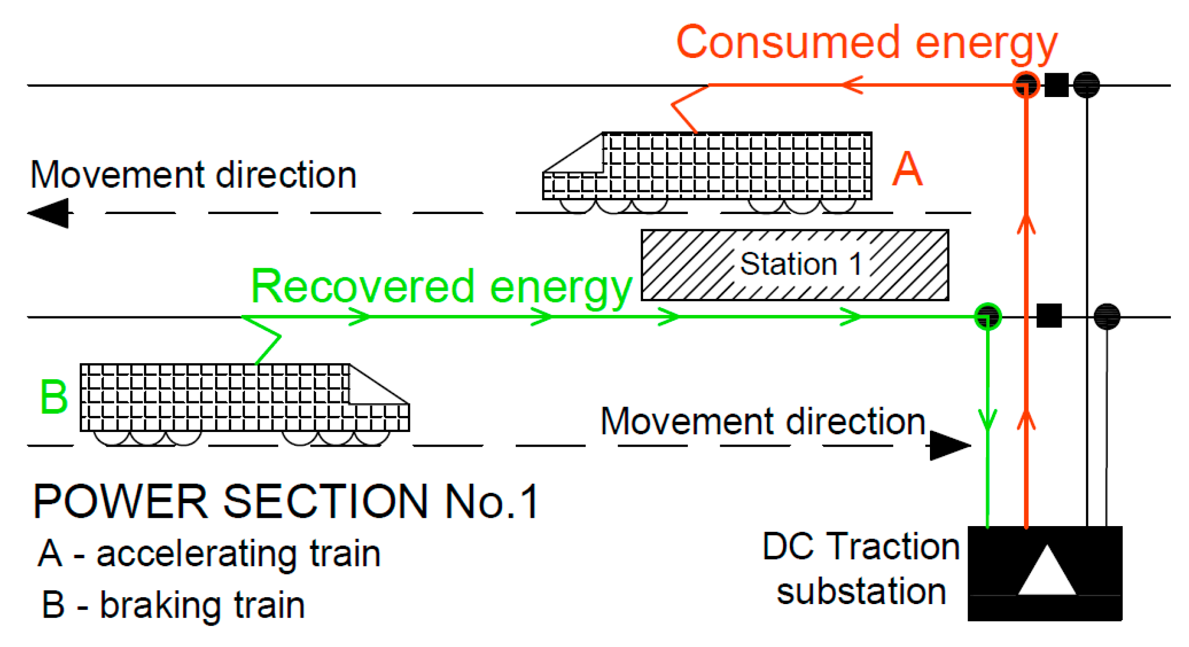
  • transferring recovered electricity back to the catenary, given the possibility of its immediate absorption by another, accelerating train.
Listed above methods have advantages and disadvantages. It is not possible to clearly indicate the best method of using energy recovered in the recuperative braking process. Nevertheless, when modern infrastructure and vehicles are available, a method that can be considered cost-free in the context of infrastructure is the transmission of recovered electricity directly to the catenary and the immediate reuse by other trains. For better efficiency of using the recovered energy directly by other trains, it is necessary to adjust the timetables. For this purpose, overlapping times of accelerating and braking down vehicles and a criterion corresponding to the recuperation effectiveness should be introduced. If the technology enabling regenerative braking is not applied or incorrect method of using this energy is picked, then all excess energy is lost in braking e.g., will be converted to thermal energy on resistors [9].

2. Energy Recovery in Railway Systems Literature Review

2.1. Energy Storage

Both onboard energy storage (located on or in the trains) and wayside energy storage (located along the route, e.g., in traction substations), can be elements increasing the efficiency of using energy from regenerative braking [10,11,12,13]. Principle of operation of both systems consists of using the battery charging cycle during regenerative braking and then discharging them using stored energy, e.g., for accelerating the train.
Picking one of the above methods always depends on the specific case. In general, energy storage used in the regenerative braking system should call for the following features [9]:
  • large number of load cycles,
  • high power capacities,
and especially for onboard systems:
  • intermediate energy storage capacity,
  • reduced weight and volume.
Onboard energy storage used in urban and suburban rail transport has the potential for very large savings up to 35%. Accumulator batteries, lead-acid batteries, nickel-metal hydride (NiMH), lithium-polymer, lithium-ion (Li-ion) and, above all, supercapacitors can be used as storage. The examples cited in the literature show that the use of such a solution in existing transport systems can reduce the cost of traction energy consumed by as much as 15% to 35% [4,14,15]. In addition, the use of onboard storage system to accumulate energy from regenerative braking can help to reduce the occurrence of so-called “power peaks” [16]. This solution also helps to ensure voltage stability in the catenary [17], and also allows for the use of so-called hybrid “autonomous vehicles” that can move without connection to the catenary, using only energy stored e.g., in supercapacitors (e.g., in historic parts of the city) [18,19,20].
Table 1 presents examples of applied, tested or developed solutions in urban and suburban rail transport in the world, using onboard energy storage. Most of such solutions are based on the use of electrochemical double-layer capacitors (EDLC), also known as supercapacitors. This is due to their properties, such as the ability to charge and discharge quickly, high power density and a relatively low price (from about $2400 per kWh of energy storage). Among the disadvantages of using onboard energy storage devices, the increase in the total weight of the train must be mentioned and hence the reduction of its performance while maintaining the original technical parameters [21].
In contrast to a system using onboard energy storage, the use of stationary storage is characterized by higher energy losses. This results from the necessity of transferring energy recovered during braking over longer distances to energy storage systems located along the railroad and usually integrated into traction substations. Then the energy stored in such substations can be returned to the catenary, e.g., in the case of temporary voltage drops. The solution using stationary storage can also be successfully used to improve energy balance in rail transport. In their work, Barrero et al. [22] or Teymourfar et al. [23] presented technical solutions using stationary energy storage system (ESS) made of supercapacitor that allow for reducing traction energy consumption depending on the traffic volume by 18% to 36%. Model of Barrero et al. can simulate the energy exchange among simultaneously running vehicles of a metro line. It can also evaluate the effect of a stationary ESS when installed along the line. In turn, Teymourfar et al. have proposed a useful method to predict the maximum instantaneous regenerative energy. That energy is delivered to each station before applying ESS and based on that the ESS configuration for each station on line 3 of Tehran metro network is determined.
The examples of applications are presented in Table 2. It shows that the dominant technology among stationary storage batteries are EDLC batteries. There are also solutions using kinetic storage systems, e.g., high-speed flywheels. The possibility of their application is dictated mainly by the lack of imposed restrictions in terms of mass or volume of such a device.

2.2. Reversible Substations

In the case of traction supply by direct current (DC), the possibility of transferring energy recovered during the braking to the national power grid is provided by specialized traction substations (reversible substations) transforming the DC to the alternating current (AC). In this method, similarly to the case of stationary storage systems, there are increased energy losses due to the resistance of the catenary when transferring energy over longer distances. There are also additional losses related to the transformation process from AC to DC. Undoubted advantages of the system include increasing the efficiency of the global energy system, and in the case of energy resale to the national system, cost savings of 7% to 14% of traction energy expenditure are possible—as demonstrated by Warin et al. [24], Ibaiondo et al. [25], or Cornic [26]. In particular, Ibaiondo has presented an energy recovery system with feedback to the distribution grid. This system is based on real data intake and validated simulations. The method involves the connection in a cascade of a DC/DC elevator to a 3-phase inverter so that the system doesn’t have limitations imposed by voltage fluctuations in the grid. This makes it possible the maximum recovery energy also at minimum catenary’s voltages. In turn, Cornic has presented a concept transforms the traditional unidirectional dc traction into a reversible one. This method maintains the priority to natural exchange of energy between trains. DC traction power supply systems from 600 V DC up to 3 kV DC are suitable for using this method.
Energy recovery and its transfer to the national power system are not as popular as the use of energy storage systems. This is mainly due to higher investment costs. This solution using reversible substations can be found mainly on modernized, revitalized, and newly created railway transport systems (Table 3).

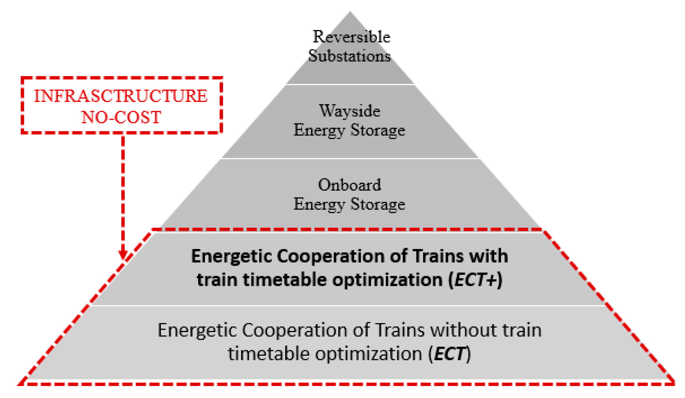
2.3. Energetic Cooperation of Trains (ECT)

Transfer energy recovered during braking back to the catenary is necessary to apply the concept of immediate-use energy from recuperation by another vehicle. Existence of such a state of railway traffic, in which at least one vehicle recuperating energy, braking (B), and other one consuming energy, accelerating (A), are located on the same section of the traction power network (Figure 1) is another necessary condition [27]. The use of this method is possible without an additional interference in modern rail transport systems, and thus it can be described as infrastructurally cost-free. It should be noted that the introduction of additional elements, such as timetable optimization or adaptive control of vehicles for the purpose of increasing the efficiency of regenerative braking, may allow for achieving even greater benefits in terms of improving the energy balance [27,28,29].
An effective and cheap solution for better use of energy recovered in recuperation braking can be optimizing the timetable by synchronizing the accelerating and braking times of several different trains. Reducing the number of vehicles accelerating simultaneously and hence reducing the occurrence of so-called energy peaks are ones of the main advantages of this method next to the direct impact on the energy balance. The biggest benefits of using the above method of recovery and use of energy from recuperation can be achieved in a dense network of urban rail transport. It is caused urban rail transport where braking and accelerating trains can be synchronized without significant changes in timetables [9].
The general concepts of the possibility of using energy recovered from the braking process by another rail vehicle (e.g., tram, train) by using transmission via the catenary and properly optimizing accelerating and braking times can be found in the literature [27]. In addition, there are also detailed studies in this regard, and the results of the selected ones are presented below. In 2004, Pazdro et al. [28] proposed the method that allows the reduction in the demand for electricity in Warsaw’s metro or Tricity Rapid Urban Railway (SKM railway) by up to 30%. This method is based on proper metro vehicle traffic control and using electrodynamic braking with transfer the energy back to the catenary. In 2010, Nasri et al. [30] showed that in metro system it is possible to save up to 14% of traction energy by using timetable optimization method based on the use of genetic algorithms. In this method they used the technical reserve of time to maximize the use of recuperated energy. In 2011, Pena-Alcaraz et al. [29] showed that for Madrid’s third metro line it is possible to improve the traction energy consumption balance by 3%. They achieved it by proposing a new timetable based on a mixed-integration programming (MIP) solution of the optimization problem. They also believe that thanks to this method a further improvement of the traction energy consumption balance up to 7% is possible. In 2014, Yang et al. [31], based on the operation data from the Beijing Yizhuang subway line (China), showed that it is possible to save 8.86% of the consumed electric energy. They obtained this result by comparing current timetable with timetable formulated using two-objective integer programming model with dwell time and headway time control and solved by genetic algorithm with binary encoding.
The efficiency of direct transfer of regenerative braking energy between railway vehicles can be improved by [32]:
  • increasing the probability of the braking and accelerating cycles of several trains at the same time existing by elongating the length of power sections,
  • reducing the distance between cooperating trains or resistance of catenary which also means reducing losses and voltage drops in the energy transmission path,
  • additional use of energy storage for excess electricity,
  • increasing the voltage difference between the nearest power substation and the braking vehicle pantograph.
The above increasing efficiency methods require additional financial investment and also another research in the next step and will not be considered in this paper.

3. Materials and Methods

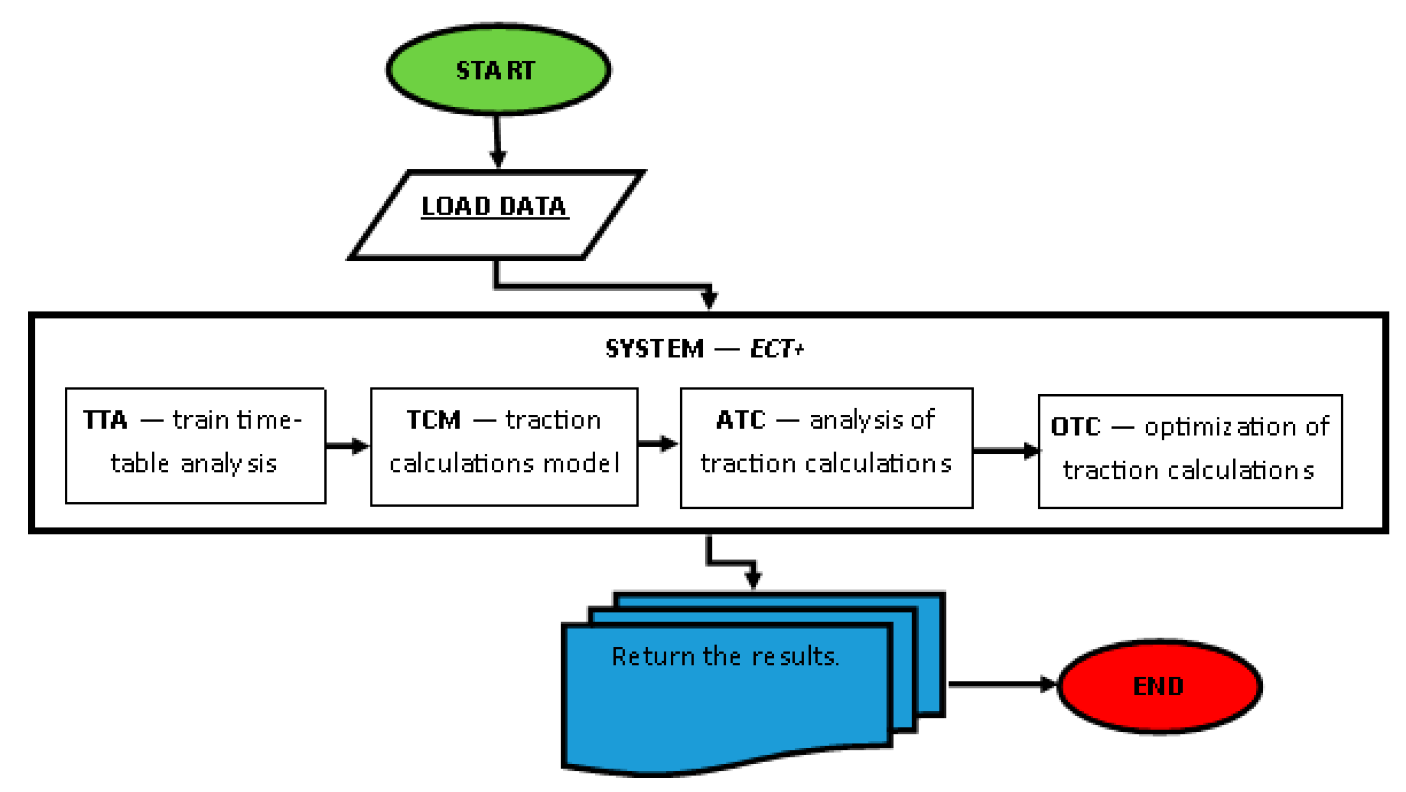
3.1. Energetic Cooperation of Trains (ECT+)

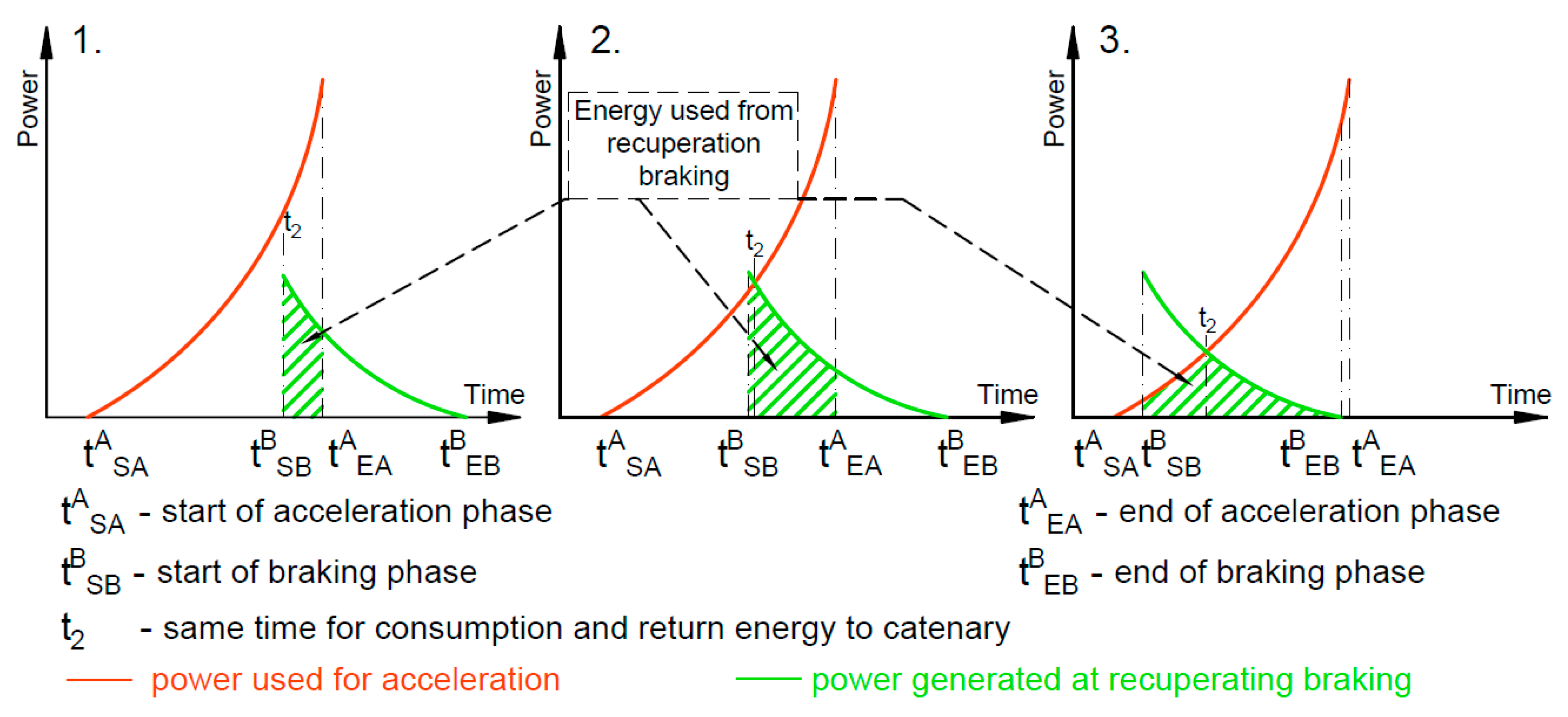
3.1.1. Choosing the Method of Using Recovered Energy

It is impossible to indicate one best universal for all scenarios method of using energy from recuperative braking. The best scenario would combine all known methods into one integrated energy recovery system. Therefore, striving for the best solution, it is necessary to carry out further investigations and perform an optimization of the recuperation energy use. The first step depends on what the overall cost function is.
Therefore first it was decided to determine what part of recovered energy can be used without infrastructural investments. Subsequently, either the energy storage system optimization or consideration of the DC to AC energy transformation and its transfer to the national energy network should take place. The discussed process is presented in the drawing below (Figure 2).
Based on the examples listed in Table 1, Table 2 and Table 3, it can be seen that energy recovery technologies are mainly used in urban (trams) and suburban (metro, rapid urban railway) transport. In connection with the abovementioned literature, this paper is focusing on lower speed trains which stop frequently. Despite this there are also commuter and high-speed long-distance services using electric trains which could use onboard or network storage equally. It should be noted, that the specificity of regenerative braking makes its efficiency drastically reduced when braking at speeds below 20 km/h and it depends on the technical characteristics of specifically used devices [33], so there is no definitive answer to question if using regenerative braking in this speed is worse than kinetic energy being dissipated as heat. It can, therefore, be concluded that the ideal branch of rail transport to fully exploit the possibilities offered by the use of regenerative braking is the metro and rapid urban railway systems, where the speeds are higher than those in the tram network.

3.1.2. Model for Using Recovered Energy

The presented model proposes to control the velocities of two cooperating trains v = vA, vB. Indirectly this allows for controlling the arrival time tEB(v) of the braking train B at the station within the permissible range (Ta1,Ta2). This model is similar to that by Su et al. [34], which assumes the control of the departure time. In our approach, we distinguished three variants. In each of the variants the departure time of the train A from the station S is constant, but the arrival time of the train B at the same station is changed (Figure 3).
It should be noted that the case presented in Figure 3 concerns the situation when the energy needed to accelerate the train to a given speed is greater than the energy possible to recover during recuperation. It happens so e.g., due to losses resulting from transmission and conversion of kinetic energy into electricity (or vice versa) in a situation when train B starts braking at the same speed as the speed finally achieved by accelerating train A. However, this does not affect to the calculation method presented below.
Cases 1, 2, 3 show the train A as a train in the acceleration phase and train B as a train in braking phase at the same time. The t S A A and t E A A mean respectively start and end of acceleration by train A and these times are the same in all variants. In the same variants the braking time t S B B (start of braking) and the end of braking time (arrival time) t E B B of the train B are changed and is getting earlier in the consecutive cases 1, 2, 3. Changing the arrival time t E B B causes that train A to use more the energy recovered during braking of the train B.
The first case in Figure 3 shows that the power generated in the recuperation braking process by the braking train P r B ( t , s ) is smaller than the power demand by the accelerating train P a A ( t , t S A A ) . Therefore, the dependence P a A ( t , t S A A ) > P r B ( t , s ) holds where s means the distance between trains and the energy used from recuperation is equal to:
E R = t = 0 t min { P a A ( t , t S A A ) , P r B ( t , s ) } d t = t S B B t E A A P r B ( t , s ) d t
In the second case, where the braking end time t E B B of the train B is earlier than in the first case, in the initial time interval [ t S A A , t 2 ] the available power from recuperation P r B ( t , s ) is greater than the power P a A ( t , t S A A ) needed to start the train A. In this time interval only a part of the power from recuperation braking is used by train A until the moment t2 where P a A ( t 2 , t S A A ) = P r B ( t 2 , s ) . As a result, train A uses the amount of the regenerative energy equal to:
E R = t S B B t 2 P a A ( t , t S A A ) d t + t 2 t E A A P r B ( t , s ) d t
In the third case, the end time t E B B of braking of the train B is earlier than the end time t E A A of acceleration of the train A. Then, the formula for the regenerative energy used by the accelerating train takes the following form:
E R = t S B B t 2 P a A ( t , t S A A ) d t + t 2 t E B B P r B ( t , s ) d t
The above considerations show that the energy recovered during recuperation can be used when the following conditions are met:
t S B B ( t S A A , t E A A ) or t E B B ( t S A A , t E A A ) .
The time t S B B at which the train B starts braking can be determined in the course of the traction calculations. It is closely related to the train speed v B on a track between the stations.
For each train, the energy used during the passage between the stations is expressed by the integral of the power due to traction force. The traction calculations and simulations are based on the Newton equation:
{ m d v d t = u ( t ) R s ( v ) R g ( x ) d x d t = v ( t )
where t denotes time, v ( t ) is the train velocity, and u ( t ) is the traction force u = F ( t ) or the braking force u = B ( t ) , depending on the phase of train motion. The running resistance R s ( v ) is mainly related to aerodynamic forces and the interaction between wheels and rails and is given by a quadratic function of v [23]. The force R g ( x ) = m g p ( x ) due to the track gradient p ( x ) depends on the train mass m , the standard gravity g , and changes with the actual train position x along the track. Detailed descriptions of such traction calculations are included, among others, in the works [33,34,35,36].

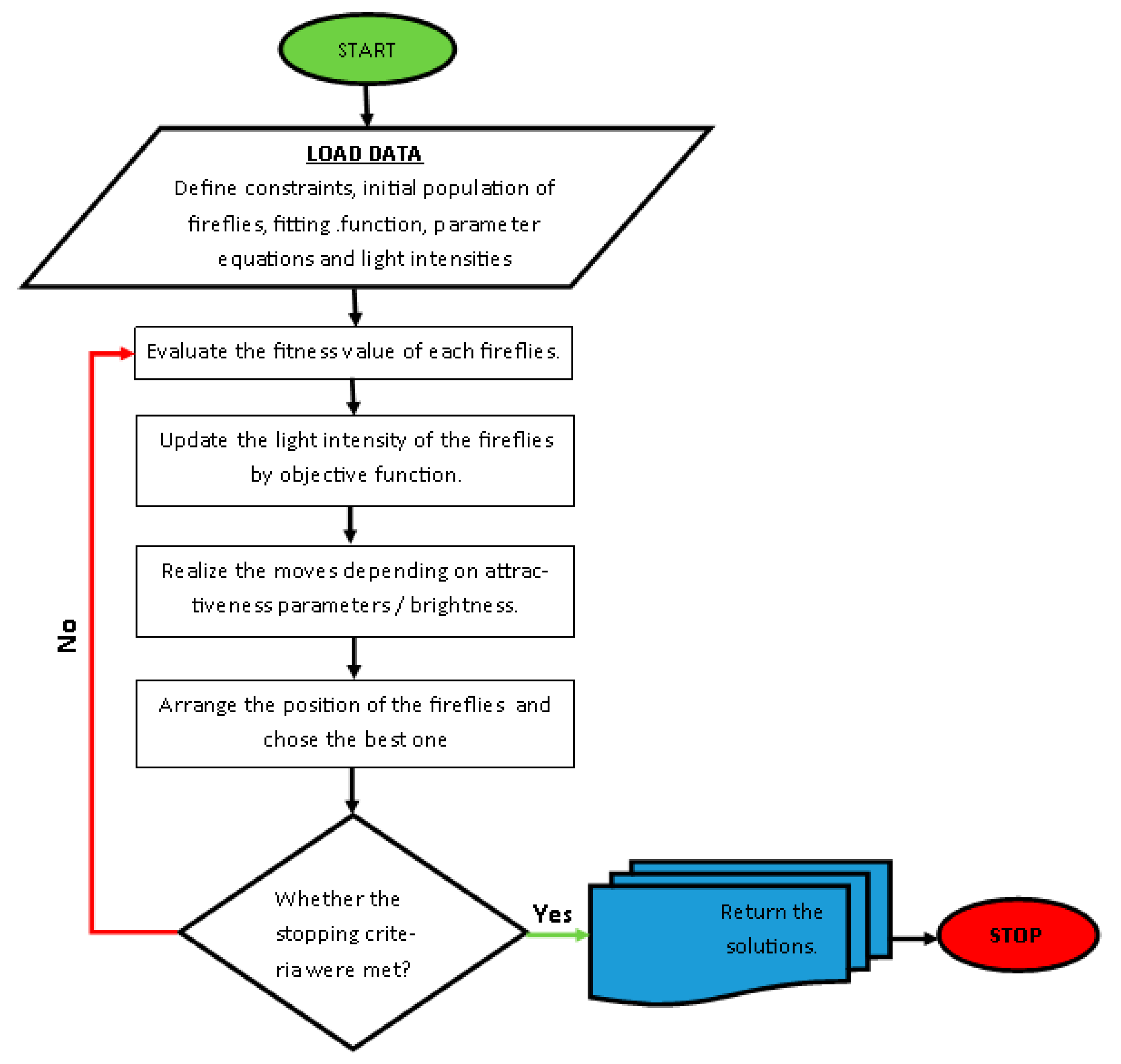
3.1.3. Optimization Model

The acceleration process generates the greatest demand for power and electricity but appropriate management of energy from the regenerative braking of another train can reduce it. In this case, demand for electricity will be equal to the energy balance of energy possible to be recovered and used from the regenerative braking and the energy needed for the acceleration [33].
The proposed approach is based on the energetic cooperation of trains present in the station area because there are the most frequent and most intense processes of accelerating and braking. It also assumes the arrival time control. Given the above, there is no need to optimize the entire passage of both trains to achieve relatively significant benefits in the energy balance. It is sufficient to analyze the passage fragment of the moving train A until the train B stops and the passage of the braking vehicle B. With advancing the arrival time of the train B the recoverable energy E R S will increase as braking will occur at higher speeds. Unfortunately, this is also associated with an increase in energy demand E on the analyzed passage section.
In connection with the above, we propose the main component of the objective function as:
E P = E E R S min ,
where:
  • E P : the actual value of the energy consumed during the passage of the train B and the passage fragment of the train A,
  • E : the amount of energy needed to perform the passage of the train B and the passage fragment of the train A,
  • E R S : energy recovered during the electrodynamic braking of vehicle B and used in the energetic cooperation of both trains B and A.
In Formula (6) E R S energy is considered with a negative sign. This is because the goals of independent optimization problems for the energies E and ERS would be to achieve a minimum value of E and the maximum value of E R S .
Individual energy values can be determined as:
E = t 0 B t E B B P B ( t ) d t + t S A A t E B B P A ( t ) d t ,
where t 0 B is the departure time of train B from the previous stop or station, and
E R S = T S B B T E B B min { φ ( s p ) P B ( t ) , P A ( t ) } d t ,
where φ is the coefficient that represents the losses occurring in the energy transmission process and takes values from the interval [0, 1]. In particular, these losses arise due to the resistance of the catenary contact lines. When the distance of electricity transmission between vehicles A and B is larger, then the coefficient φ(s) should become smaller. In the case under consideration the coefficient value was assumed φ(s) = 0.9 for energy transmission in the station area (over short distances).
As another criterion in the multi-criteria optimization process the following sub-function has been considered:
E R = T S B B t E B B P B ( t ) d t max
where E R is all the energy recovered during the recuperative braking of vehicle B which can be used for non-traction and traction purposes.
Considering the above, a global cost function has been proposed as:
F ( t E B ) = w 1 E P w 2 E R min
where w1 and w2 are weights of individual component functions which sum should be equal to 1. They reflect the importance of each criterion in existing railway network conditions. It should be also noted that the higher w1 value corresponds to a lower traction energy demand for the analyzed journey section, and the higher w2 value leads to larger amount of energy that can be recovered during recuperation and used (e.g., with additional energy storage). We can also write the global cost function in the following form:
F ( t E B ) = w 1 ( t 0 B t E B B P B ( t ) d t + t S A A t E B B P A ( t ) d t t S B B t E B B min { φ P B ( t ) , P A ( t ) } d t ) w 2 t S B B t E B B P B ( t ) d t min .
Since the braking end time ( t E B B ) is also the actual time of train B at the station, the purpose of the algorithm will be to find such a real-time of arrival T R A * (allowed by timetable and restricted to the time interval when energetic cooperation is possible) of the train B at the station for which:
F ( T R A * ) = min T R A D F ( T R A )
where the actual time of arrival of train B belongs to the time interval D, i.e., T R A ( v ) ϵ T R A 1 , T R A 2 . However, since the amount of recoverable energy and time of the actual arrival of the train B at the stop are strictly related to the speeds of both vehicles on the analyzed section, the full minimization problem takes the following form:
F ( v A * , v B * ) = min v A D A , v B D B F ( v A , v B )
where v A and v B specify fixed velocities of trains in their passages between two stations (excluding the accelerating and braking phases), where allowable speed ranges guaranteeing adherence to scheduled arrival times are represented by D A and D B .
The above optimization task (12) and (13) is solved with the Firefly Algorithm (FA). It is dedicated to the problem of minimizing the cost function in the form of F(x) with extra conditions imposed on x where, in the case under consideration, variable x is a two-dimensional variable x = ( v A , v B ) . Each firefly in FA has its attractiveness β described by monotonically decreasing function of the distance r between two any fireflies, e.g., β = β 0 e γ r j 2 . In this expression the maximum attractiveness (at rj = 0) is denoted as β0 and the light absorption coefficient, which controls the decrease of the light intensity is described as γ. The less bright (attractive) firefly is attracted and moved to the brighter one in order to find the optimal solution [37,38]. The procedure of the firefly optimization technique can be represented as in Figure 4.
All records have been programmed in the MATLAB and Simulink environment creating a general diagram as in Figure 5.

3.2. Optimization of Using Recuperative Braking Energy at Sample Railway Line

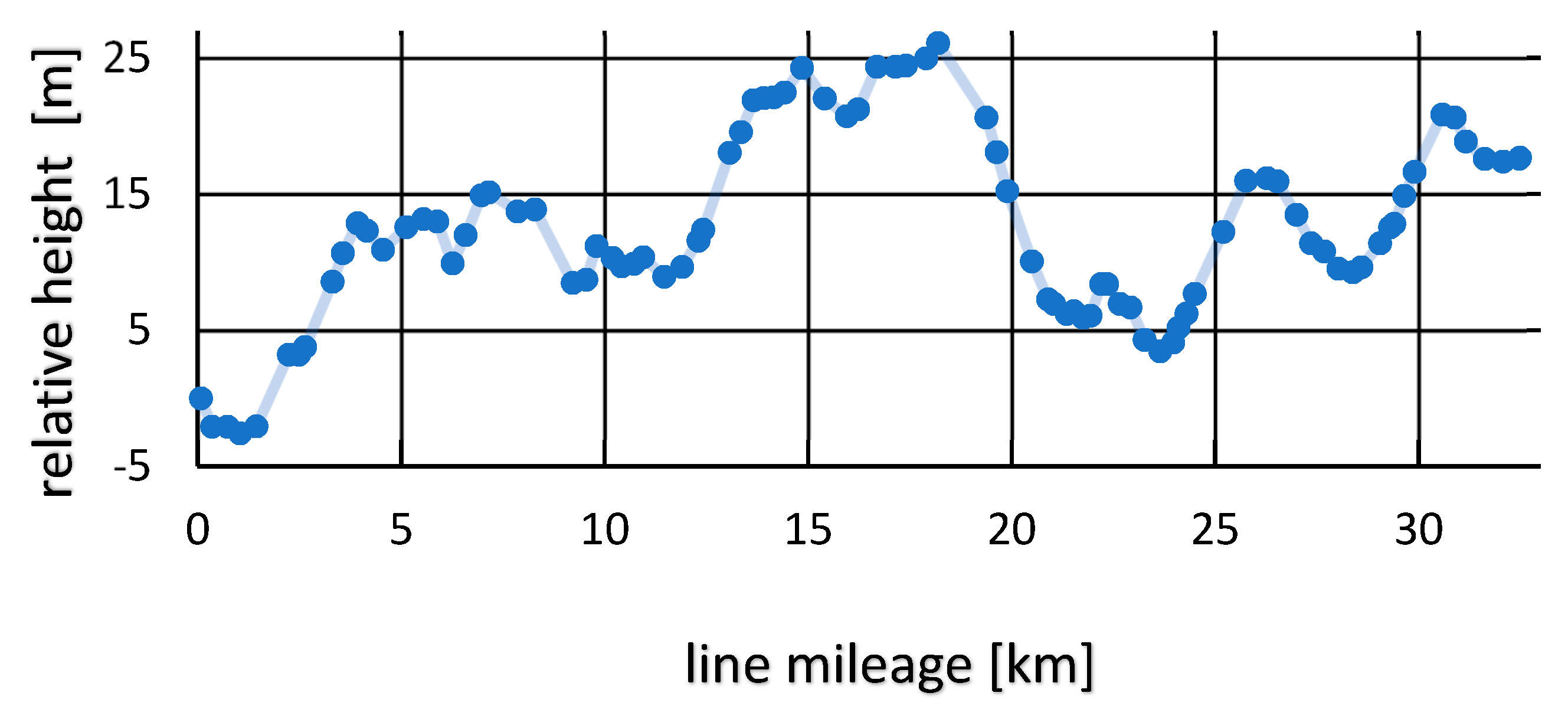
Characteristics of the Rolling Stock and Selected Railway Line

The described method of using energy recovered from recuperative braking is recommended mainly for use on urban and suburban railways. This is related to the occurrence of frequent braking and accelerating of vehicles on these lines, thus enabling efficient energy recovery. The use of energy recovery technologies with transmission to the catenary and taking into account the energy cooperation between trains is also possible in a case of long-distance trains, however, mainly under specific conditions, e.g., at stations with high levels of arrivals and departures of trains.
On these grounds, it has been decided to test the created software to simulate energetic cooperation of trains and optimize it with control of trains arrival times for selected stations and stops of the Tricity SKM railway.
Currently, the railway line No. 250 Gdańsk Główny—Rumia uses mainly electric multiple units (EMU) in the form of EN57, EN71, EN71AC, EN57AKM vehicles manufactured in the 1970s. In connection with the above, the assumption was made that the entire EMU will be unified and replaced with modern unit from the Newag Impuls 45 WE series. The 45 WE vehicle is equipped with two motor bogies and four carrying bogies (axis system Bo′2′2′2′2′Bo′). It has four motors with power of 500 kW each. They allow for achieving a total vehicle power of 2000 kW and develop speed of 160 km/h. The Impuls 45 WE has been additionally equipped with three-phase asynchronous motors and an individual inverter drive for each motor bogie enabling the energy recovery (recuperation) to the catenary during braking. The vehicle capacity is over 500 passengers, including 219 seats [39]. Detailed technical data of 45 WE are included in the Table 4.
The simulations, optimization, and analysis were carried out for the data from the timetable applicable from 13 March to 9 June 2018, available on the carrier’s website [40]. The applied longitudinal profile of the railway line No. 250 Gdańsk Główny—Rumia was prepared based on the data provided by PKP Polskie Linie Kolejowe S.A. (PKP PLK S.A., the Polish railway infrastructure manager) and is presented in a graphical form in Figure 6.

4. Results

4.1. Optimization Results for Selected Train Stops

The simulations along with optimization was carried out for the Gdańsk Żabianka AWFiS station, which meant the analysis of the Gdańsk Oliwa—Sopot Wyścigi section and conducting the simulation of energy train cooperation between ten vehicle pairs during the day, No.: 59708-9560, 59600-95603, 59710-95605, 59810-95415, 59610-95419, 59760-95761, 59468-95467, 59782-95791, 59478-95685, 59694-95697 (part presented in Figure 7).
When determining the values of the individual factor weights, it is assumed that, since the main objective of the investigated method is the use of the regenerative braking energy by other trains, the energy E P should be considered as the most important component of the objective function while the value of E R , determining the potential energy to be stored in energy storage, is less important. For preliminary studies, to distinguish the validity of criteria accordingly, the initially weights w1 = 0.6 and w2 = 0.4 have been adopted. If we increase the weight of w2, the results obtained will favor faster travel speeds allowing for the recovery more volume of electric energy ER. At the same time, this will affect the greater real energy demand of EP. Conversely, if we increase the weight of w1 then the results obtained will favor lower travel speeds requiring less volume of electric energy, but also giving less potential for recovery and storage energy.
At the beginning, the developed software was used to analyze the variation of the objective function F ( v A , v B ) at the constant speed of the train A ( v A ) and the variable speed of the train B ( v B ), regardless of the optimization algorithm. The velocity v B determines the arrival clock time T R A (expressed in decimal number format in units of hours) of train B which is restricted by the technical reserve admissible in the timetable. The simulation (Figure 8) shows that the values of the objective function for speed v A = 50 km/h (marked in blue) and v A = 60 km/h (marked in red) at the beginning decrease with the delay of the arrival time T R A of train B then they start to grow and once they cross some limit value, they start to decline again. In the case of v A = 70 km/h (marked in yellow), the values of the objective function at the beginning decrease with the delay of the train B arrival T R A , and then increase.
The optimizing module was then tested to determine the optimal values of the target function, assuming a constant speed of the A train ( v A ) and a variable speed of the B train ( v B ) or at a constant speed of the B train ( v B ) and a variable speed of the A train ( v A ). The obtained results are presented in Figure 9. The values of all solutions (fireflies) in each iteration carried out at constant speeds are marked with blue for the speed of 50 km/h, red for 60 km/h, and yellow for 70 km/h. It is found that, in the case of the assumed constant train B speed ( v B ), the objective function increases with the increase of the train A speed ( v A ) in the whole range allowed by technical time reserves included in the timetable. Assuming a constant speed of the train A ( v A ), it can be noted that the value of the objective function is gradually decreasing with increasing the speed of train B ( v B ) until it reaches a certain limit value, after which it starts to grow. The same behavior of the objective function is characterized by a graph of its variation with the arrival time of the train B ( T R A ) at the stop, as also shown in Figure 9.
Then, using the implemented FA algorithm, the full optimization was performed with respect to both v A and v B variables (Figure 10), resulting in the optimal value of the objective function: F ( v A , v B ) = 7.4583 kWh.
The values of individual partial functions corresponding to the optimal value of the global objective function are equal to E P = 15.3720 kWh , E R = 9.6785 kWh and the actual arrival time of train B at the stop is T R A = 5.4909 h (expressed in decimal number format in units of hours), which corresponds to the arrival clock time of the train No. 59708 at the Gdańsk Żabianka AWFiS stop at 5:29:27 [hour:min:sec]. The variation of the objective function F ( v A , v B ) depending on the arrival time TRA of the train No. 59708 for three basic weights of the optimization subcriteria is shown in Figure 11, where the points marked on the graph indicate the values of the solutions (fireflies) in each iteration. It is found that increasing the weight w2 (and simultaneously lowering w1 = 1 − w2) leads to earlier optimal arrival time TRA, corresponding to the minimum of the objective function. This is so because an earlier TRA corresponds to the shorter passage of train B between the stations and thus its larger speed vB and, consequently, to a greater volume ER of energy recovered during braking, as already mentioned above. In the specific case presented in Figure 11, the optimal arrival time TRA does not change significantly (around 0.0006 h, i.e., 2.2 s) when w2 is changed from 0 to 1 because the earliest possible arrival time (TRA = 5.4905 h) is limited the timetable. Let us also note that, for sufficiently large value of w2 (in particular for w2 = 1), the global objective function is negative since it dominated by its second term −w2ER where the negative sign has been chosen to define the global objective function which has a minimum (the energy ER alone can be maximized).
The above results of the FA optimization correspond to the passage of the train B No. 59708 at the speed v B = 65.3699 km / m = 18.1583 m / s and the passage of the train A No. 95601 at the speed equal to v A = 50.3310 km / h = 13.9808 m / s . It should be also noted that in the above case, the arrival time T R A varies during optimization within the range of 12 s ( T R A saved as clock time ranges from 05:29:26 to 05:29:38).
The variation of the value of the objective function F ( v A , v B ) in the FA algorithm depending on the travel speed of both trains v A and v B has been presented in Figure 12.
The above simulation was performed for all train pairs, for which it is possible to cooperate energetically, at three exemplary stops of Tricity SKM railway: Gdańsk Żabianka AWFiS (59708-95601, 59600-95603, 59710-95605, 59810-95415, 59610-95419, 59760-95761, 59468-95467, 59782-95791, 59478-95685, 59694-95697), Gdynia Orłowo (59716-95719, 59606-95721) and Gdynia Cisowa (59710-95601, 59760-95757, 59816-95759, 59612-95633, 59766-95761). It is worth noting, that among the above train pairs there are those where trains travel from Lębork direction (59708, 59600, 59710, 59810, 59760, 59782, 59478, 59694, 59710, 59760, 59816, 59612, 59766), as well as from the Gdańsk Śródmieście stop (95419, 95467, 95719, 95721). The optimization results based on the simulations carried out are presented in Table 5.

4.2. Summary of Findings

Using the FA algorithm we have obtained the following average results of simulation and optimization of the trains energetic cooperation at the double-track railway line stop areas:
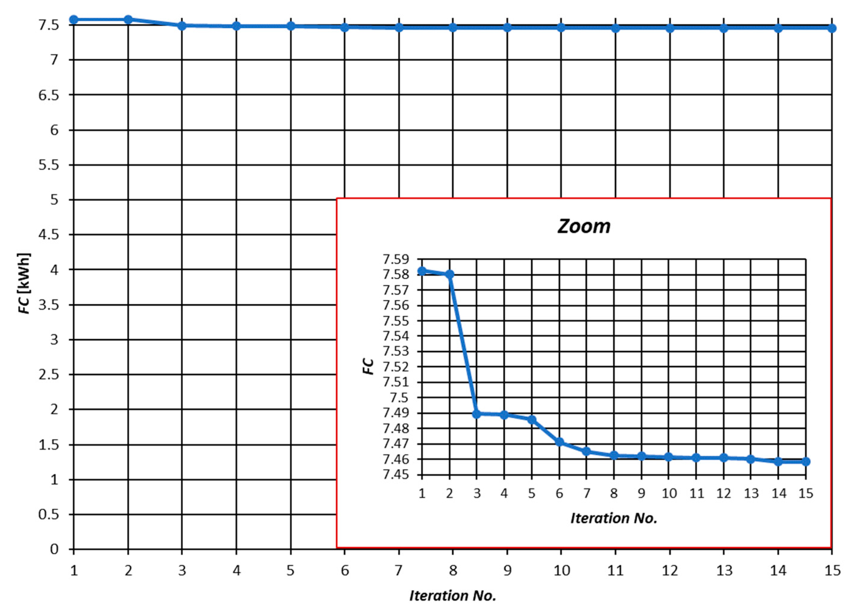
  • the value of energy that can be reused during energetic cooperation of a train pair ERS = 5.7555 kWh,
  • the value of energy recoverable in the recuperation process ER = 8.7745 kWh,
  • the value of energy required to make a selected part of the drive EP = 15.3863 kWh,
  • the value of global function F(vA*, vB*) = 7.8826 kWh.

5. Discussion and Conclusions

There are many ways to use the energy recovered during recuperative braking. However, only the return to the catenary and the inclusion of trains energy cooperation gives the opportunity to effectively use the recovered energy without incurring additional costs related to the infrastructure. It must also be noted that to improve the effects of ECT it is necessary to coordinate accelerating and braking trains by timetable optimization.
Among the existing models describing the optimization of the timetable for more effective use of energy recuperation with the cooperation of trains, two main approaches can be distinguished: creating the train timetable from scratch including the criterion of recuperation, and the other one: controlling the trains departure time from stations/stops using technical time reserves.
The present authors propose an alternative model of optimization assuming no changes in the existing timetable and using the technical reserve of time to change trains arrival times at the station (TRA). The proposed weighted objective function takes into account the actual value of energy consumed by a pair of cooperating trains (EP) as well as the total energy recovered during recuperative braking possible to be used in a different way than a direct transmission to the catenary (ER, e.g., by using energy storage or reversible substations).
Using the developed program for simulation of journey of train pairs and their energetic cooperation with the FA optimization at selected stops on a double-track railway line, it was shown that it is possible to use energy recovery technology with ECT and its efficiency can be increased by changing the actual arrival time without interfering with the existing timetable (ECT+). During the simulation using the FA algorithm, it was shown that in the range of real arrival time change by 12 s it is possible to reduce the global function by as much as 3.6286 kWh.
At the next step in future investigations, the analysis and construction of a complete railway energy recovery system, validation of weights in various conditions and priorities, adjustment of the model for long-distance trains, and finally the introduction of the method and verification of results in real will be included.

Author Contributions

Conceptualization, M.U.; methodology, M.U. and E.K.-C.; software, formal analysis, E.K.-C. and M.J.; investigation, M.U.; data curation, M.U.; writing—original draft preparation, M.U.; writing—review and editing, E.K.-C. and M.J.; visualization, M.U.; supervision, M.J.

Funding

This research received no external funding.

Conflicts of Interest

The authors declare no conflict of interest.

References

  1. Jachimowski, R.; Szczepański, E.; Kłodawski, M.; Markowska, K.; Dąbrowski, J. Selection of a container storage strategy at the rail-road intermodal terminal as a function of minimization of the energy expenditure of transshipment devices and CO2 emissions. Annu. Set Environ. Prot. 2018, 20, 965–988. [Google Scholar]
  2. Wasiak, M.; Jacyna-Gołda, I.; Markowska, K.; Jachimowski, R.; Kłodawski, M.; Izdebski, M. The use of a supply chain configuration model to assess the reliability of logistics processes. Eksploat. Niezawodn. 2019, 3, 367–374. [Google Scholar] [CrossRef]
  3. Szeląg, A. Electrical power infrastructure for modern rolling stock with regard to the railway in Poland. Arch. Transp. 2017, 42, 75–83. [Google Scholar] [CrossRef]
  4. Jacyna, M.; Szczepański, E.; Izdebski, M.; Jasiński, S.; Maciejewski, M. Characteristics of event recorders in Automatic Train Control systems. Arch. Transp. 2018, 46, 61–70. [Google Scholar] [CrossRef]
  5. Jacyna, M.; Gołębiowski, P.; Urbaniak, M. Multi-option model of railway traffic organization including the energy recuperation. Chall. Transp. Telemat. 2016, 640, 199–210. [Google Scholar]
  6. Jacyna-Gołda, I.; Izdebski, M.; Podviezko, A. Assessment of the efficiency of assignment of vehicles to tasks in supply chains: A case-study of a municipul company. Transport 2017, 32, 243–251. [Google Scholar] [CrossRef]
  7. Jacyna, M.; Izdebski, M.; Szczepański, E.; Gołda, P. The task assignment of vehicles for a production company. Symmetry 2018, 11, 551. [Google Scholar] [CrossRef]
  8. González-Gil, A.; Palacin, R.; Batty, P. Sustainable urban rail systems: Strategies and technologies for optimal management of regenerative braking energy. Energy Convers. Manag. 2013, 75, 374–388. [Google Scholar] [CrossRef]
  9. González-Gil, A.; Palacin, R.; Batty, P.; Powell, J. Energy-efficient urban rail systems: Strategies for an optimal management of regenerative braking energy. In Proceedings of the Transport Research Arena 2014, Paris, France, 14–17 April 2014. [Google Scholar]
  10. Akiyama, S.; Tsutsumi, K.; Matsuki, S. The Development of Low Floor Battery-Driven Lrv “SWIMO”. Available online: www.railway-research.org/IMG/pdf/r.2.2.3.2.pdf (accessed on 1 June 2019).
  11. Kono, Y.; Shiraki, N.; Yokoyama, H.; Furuta, R. Catenary and Storage Battery Hybrid System for Electric Railcar Series EV-E301. In Proceedings of the International Power Electronics Conference 2014, Hiroshima, Japan, 18–21 May 2014. [Google Scholar]
  12. Batteries Included: Prototype Battery-Powered Train Carries Passengers for First Time. Available online: http://www.networkrailmediacentre.co.uk/news/batteries-included-prototype-battery-powered-train-carries-passengers-for-first-time (accessed on 1 June 2019).
  13. Ribeiro, P.; Johnson, B.; Crow, M.; Arsoy, A.; Liu, Y. Energy storage systems for advanced power applications. IEEE Trans. Med. Imaging 2001, 12, 1744–1756. [Google Scholar] [CrossRef]
  14. Chymera, M.; Renfrew, A.; Barnes, M. Analizing the potential of energy storage on electrified transit systems. In Proceedings of the World Congress on Railway Research—WCRR 2008, Seoul, Korea, 22 May 2008. [Google Scholar]
  15. Dominguez, M.; Cucala, A.P.; Fernandez, A.; Pecharroman, R.R.; Blanquer, J. Energy efficiency on train control—Design of metro ATO driving and impact of energy accumulation devices. In Proceedings of the World Congress on Railway Research—WCRR 2011, Lille, France, 22–26 May 2011. [Google Scholar]
  16. Iannuzzi, D.; Tricoli, P. Metro trains equipped onboard with super-capacitors: A control technique for energy saving. In Proceedings of the SPEEDAM 2010—International Symposium on Power Electronics, Electrical Drives, Automation and Motion, Pisa, Italy, 14–16 June 2010. [Google Scholar]
  17. Ciccarelli, F.; Tricoli, P.; Iannuzzi, D. Control of metro-trains equipped with onboard supercapacitors for energy saving and reduction of power peak demand. Transp. Res. Part C Emerg. Technol. 2012, 24, 36–49. [Google Scholar] [CrossRef]
  18. Allegre, A.L.; Bouscayrol, A.; Delarue, P.; Barrade, P.; Chattot, E.; El-Fassi, S. Energy storage system with supercapacitor for an innovative subway. IEEE Trans. Ind. Electron. 2010, 57, 4001–4012. [Google Scholar] [CrossRef]
  19. Swanson, J. Light rail systems without wires? In Proceedings of the Rail Conference 2003, Chicago, IL, USA, 22–24 April 2003. [Google Scholar]
  20. Taguchi, Y.; Terada, Y.A.; Miki, M.; Hatakeda, K.; Kimura, T. Evaluation of a Thermal Network Model for the Traction Battery of the Battery-Powered EMU. In Proceedings of the Vehicle Power and Propulsion Conference 2015, Montreal, QC, Canada, 19–22 October 2015; pp. 1–6. [Google Scholar]
  21. Urbaniak, M.; Jacyna, M.; Kardas-Cinal, E. Metody wykorzystania energii z rekuperacji w transporcie szynowym. Tech. Transp. Szyn. 2016, 12, 355–359. (In Polish) [Google Scholar]
  22. Barrero, R.; Tackoen, X.; van Mirelo, J. Stationary or onboard energy storage systems for energy consumption reduction in a metro network. Proc. Inst. Mech. Eng. Part F J. Rail Rapid Transit 2010, 224, 207–225. [Google Scholar] [CrossRef]
  23. Teymourfar, R.; Asaei, B.; Iman-Eini, H.; Nejati Fard, R. Stationary super-capacitor energy storage system to save regenerative braking energy in metro line. Energy Conver. Manag. 2012, 56, 206–214. [Google Scholar] [CrossRef]
  24. Warin, Y.; Lanselle, R.; Thiounn, M. Active substation. In Proceedings of the World Congress on Railway Research—WCRR 2011, Lille, France, 22–26 May 2011. [Google Scholar]
  25. Ibaiondo, H.; Romo, A. Kinetic energy recovery on railway systems with feedback to the grid. In Proceedings of the World Congress on Railway Research—WCRR 2011, Lille, France, 22–26 May 2011. [Google Scholar]
  26. Cornic, D. Efficient recovery of breaking energy through a reversible DC substation. In Proceedings of the World Congress on Railway Research—WCRR 2011, Lille, France, 22–26 May 2011. [Google Scholar]
  27. Pazdro, P. Koncepcja ruchowej optymalizacji efektywności hamowania odzyskowego. Tech. Transp. Szyn. 2013, 1–2, 62–64. (In Polish) [Google Scholar]
  28. Czucha, J.; Karwowski, K.; Mizan, M.; Pazdro, P. Efektywność odzysku energii hamowania elektrodynamicznego w komunikacji miejskiej. Przegląd Elektrotechniczny 2004, 80, 1016–1019. (In Polish) [Google Scholar]
  29. Pena-Alcaraz, M.; Fernández, A.; Cucala, A.; Ramos, A.; Pecharromán, R. Optimal underground timetable design based on power flow for maximizing the use of regenerative-braking energy. Proc. Inst. Mech. Eng. Part F J. Rail Rapid Transit 2012, 226, 397–408. [Google Scholar] [CrossRef]
  30. Nasri, A.; Fekri Moghadam, M.; Mokhtari, H. Timetable optimization for maximum usage of regenerative energy of braking in electrical railway systems. In Proceedings of the SPEEDAM 2010—International Symposium on Power Electronics, Electrical Drives, Automation and Motion, Pisa, Italy, 14–16 June 2010. [Google Scholar]
  31. Yang, X.; Ning, B.; Li, X.; Tang, T. A Two-Objective Timetable Optimization Model in Subway Systems. IEEE Trans. Intell. Transp. Syst. 2014, 5, 1913–1921. [Google Scholar] [CrossRef]
  32. Szeląg, A. Efektywność hamowania odzyskowego w zelektryfikowanym transporcie szynowym. Pojazdy Szynowe 2009, 4, 9–16. (In Polish) [Google Scholar]
  33. Podoski, J.; Masłek, J.; Kacprzak, J. Zasady Trakcji Elektrycznej; Wydawnictwo Komunikacji i Łączności: Warsaw, Poland, 1980. (In Polish) [Google Scholar]
  34. Su, S.; Tang, T.; Roberts, C. A Cooperative Train Control Model for Energy Saving. IEEE Intell. Transp. Syst. Soc. 2015, 16, 622–631. [Google Scholar] [CrossRef]
  35. Su, S.; Tang, T.; Wang, Y. Evaluation of Strategies to Reducing Traction Energy Consumption of Metro Systems Using an Optimal Train Control Simulation Model. Energies 2016, 9, 105. [Google Scholar] [CrossRef]
  36. Urbaniak, M. The Model of Railway Traffic Organization Given an Energy Recuperation. Ph.D. Thesis, Warsaw University of Technology, Faculty of Transport, Warsaw, Poland, 2018. [Google Scholar]
  37. Yang, X.S. Firefly algorithms for multimodal optimisation. Comput. Sci. 2009, 5792, 169–178. [Google Scholar]
  38. Yang, X.S. Nature-Inspired Metaheuristic Algorithms, 2nd ed.; Luniver Press: Sunnyvale, CA, USA, 2010. [Google Scholar]
  39. Elektryczne Zespoły Trakcyjne z Rodziny Impuls. Available online: http://www.newag.pl/oferta/elektryczne-zespoly-trakcyjne/impuls/ (accessed on 1 June 2019). (In Polish).
  40. Timetable for PKP Szybka Kolej Miejska w Trójmieście Sp.zo.o. Available online: https://www.skm.pkp.pl/dla-pasazera/informacje-dla-podroznych/szczegoly-informacji (accessed on 1 June 2019). (In Polish).
Figure 1. The scheme of using regenerative braking energy by another vehicle. Source: own study based on [27].
Symmetry 11 01175 g001
Figure 2. The diagram of the order of methods of using energy from regenerative braking. Source: own study based on [21].
Symmetry 11 01175 g002
Figure 3. Control of arrival time at the station. Source: own study based on [24].
Symmetry 11 01175 g003
Figure 4. The procedure of the firefly optimization technique. Source: own study based on [37,38].
Symmetry 11 01175 g004
Figure 5. The general scheme of the system solving the described optimization problem. Source: own study based on [36].
Symmetry 11 01175 g005
Figure 6. Profile of track No. 1 of railway line No. 250. Source: own study based on PKP PLK S.A. data.
Symmetry 11 01175 g006
Figure 7. Selected trains pairs at the Gdańsk Żabianka AWFiS stop with the possibility of energy cooperation.
Symmetry 11 01175 g007
Figure 8. Variation of the objective function FC = F(vA,vB) [kWh] depending on the real arrival time TRA [h] (within the range allowed by the timetable) at a constant speed vA of train A without considering the optimization algorithm.
Symmetry 11 01175 g008
Figure 9. Results of the optimization using the FA algorithm at a variable speed of the train A (vA) or the train B (vB) or depending on the real arrival time TRA [h] train B (within the range allowed by the timetable) for weights of the optimization subcriteria w1 = 0.6, w2 = 0.4.
Symmetry 11 01175 g009
Figure 10. Values of the objective function in successive iterations of the FA algorithm for weights of the optimization subcriteria w1 = 0.6, w2 = 0.4.
Symmetry 11 01175 g010
Figure 11. Chart variation of FC = F(vA,vB) [kWh] value based on FA algorithm depending on the actual train No. 59708 arrival time TRA [h] at the stop within the range allowed by the timetable.
Symmetry 11 01175 g011
Figure 12. Variation of FC = F(vA,vB) [kWh] value based on FA algorithm depending on the speed of trains No. 95601 (vA) and 59708 (vB) for weights of the optimization subcriteria w1 = 0.6, w2 = 0.4.
Symmetry 11 01175 g012
Table 1. Onboard energy storage developed by international manufacturers in railway transport.
TechnologyMain FeaturesApplication in Urban RailYear
EDLCRated power: 288 kW
Capacity: 0.85 kWh
Weight: 820 kg
Dimensions: 2000 × 1520 × 630 mm
Commercial application in Innsbruck tramway (Germany)2012
EDLCRated power: N/A
Capacity: 0.8 kWh
Weight: 800 kg
Dimensions: N/A
Commercial application in Seville, Saragossa (Spain) and Granada tramway systems, in service (France)2012/2010
Li-ionRated power: N/A
Capacity: 40 kWh
Weight: 3200 kg
Dimensions: N/A
Prototype tests in Charlotte (USA)2010
NiMHRated power: 250 kW
Capacity: 120 kWh
Weight: 3200 kg
Dimensions: N/A
Prototype tests in Sapporo Municipal Transport network (Japan)2011
Source: own study based on [9,21].
Table 2. Trackside energy storage developed by international manufacturers in railway transport
TechnologyMain FeaturesApplication in Urban RailYear
EDLCGenerated voltage: 750 V
Rated power: 300–1000 kW
Capacity: 1–4 kWh
Pilot project for Lyon tramway2011/Adetel
EDLCGenerated voltage: 500–1850 V
Rated power: 750–4500 kW
Capacity: 0.8–16.5 kWh
Warsaw metro, to be implemented, pilot project for Philadelphia transit system (battery-based)2012/2016/ABB
FlywheelGenerated voltage: N/A
Rated power: 500 kW
Capacity: N/A
Los Angeles metro line2013/Vycon
NiMHGenerated voltage: 600–1500 V
Rated power: N/A
Capacity: 150–400 kWh
New York City Transit network, pilot project2011/Ogura
Li-ionGenerated voltage: 700 V
Rated power: 900–1500 kW
Capacity: 600–40 kWh
Philadelphia transit system, pilot project2012/Polulin
Source: own study based on [9,21].
Table 3. Examples of reversible substations currently available on the market.
CompanyMain FeaturesReferencesYear
AlstomRated voltage: 750 V
Rated power: 0.3 MW
Metro line in London and Milan2011
SiemensRated voltage: 750–1500 V
Rated power: 1.5–2.2 MW
Tested in Oslo’s and Holmenkollen’s metro line2011
ABBRated voltage: 600/750 V
Rated power: 0.5–1 MW
Tramway in Łódź and Olsztyn (Poland)2014/2016
Source: own study based on [9,21].
Table 4. Selected technical parameters of Impuls 45 WE.
Number of cars5
FormationBo′2′2′Bo′ + Bo′2′2′Bo′
Own weight159 t +/− 3%
Gross weight202 t +/− 3%
Rated power2000 kW
Traction system3000 V
Maximum speed160 km/h
Acceleration for 0–40 km/h1.0 m/s2
Acceleration above 40 km/h≥1.0 m/s2
Deceleration of operational braking≥0.8 m/s2
Deceleration of emergency braking≥1.0 m/s2
Recuperationyes
Source: own study based on [38].
Table 5. Results of the optimization using the FA algorithm.
Trains No.ERS [kWh]ER [kWh]EP [kWh]F(vA*, vB*) [kWh]TRA [h:min:s] (Clock Time)vA [km/h]vB* [km/h]
AB
Gdańsk Żabianka AWFiS
95601597085.87759.678515.37207.45835:29:2750.3365.37
95603596005.95879.693715.40807.48006:04:2850.5865.47
95605597106.42619.037415.93517.95536:29:2955.3663.17
95415598105.95878.938016.05148.04788:34:2955.8262.8
59610954196.25348.901916.98998.64308:55:2951.4963.47
95761597606.24419.600515.65767.653414:59:2853.2965.16
59468954676.42378.901917.81479.137917:55:2957.0663.47
95791597826.38379.756115.39007.452718:04:2750.265.65
95685594786.59219.595715.37797.485319:59:2850.4465.09
95697596946.38079.839115.42407.452022:49:2750.165.94
Gdynia Orłowo
59716957197.00439.16.5918.31829.37577:13:2758.0264.67
59606957217.11099.219018.30299.36717:28:2858.0664.9
Gdynia Cisowa
95601597106.16077.919315.60928.43765:58:0356.8156.71
95757597605.36257.854314.06607.489814:28:2549.7556.4
95759598160.07805.60438.81206.201715:09:0147.0645.87
95633596125.02997.901213.70997.285315:20:2447.1756.59
95761597664.59867.951413.32867.080715:29:2344.0356.87

