Article

A Hybrid Active Filter Using the Backstepping Controller for Harmonic Current Compensation

1
IMII Laboratory, Faculty of Science and Technology, Hassan First University, Settat 26000, Morocco
2
Department of Engineering, University of Almeria, CeiA3, Carretera de Sacramento s/n, 04120 Almeria, Spain
3
Department of electrical engineering, University of Mohamed-Cherif Messaadia of Souk Ahras, P.O. Box 1553, Souk Ahras 41000, Algeria
*
Author to whom correspondence should be addressed.
Symmetry 2019, 11(9), 1161; https://doi.org/10.3390/sym11091161
Submission received: 24 June 2019 / Revised: 6 September 2019 / Accepted: 6 September 2019 / Published: 12 September 2019
(This article belongs to the Special Issue Symmetry in Renewable Energy and Power Systems)

Abstract

:
This document presents a new hybrid combination of filters using passive and active elements because of the generalization in the use of non-linear loads that generate harmonics directly affecting the symmetry of energy transmission systems that influence the functioning of the electricity grid and, consequently, the deterioration of power quality. In this context, active power filters represent one of the best solutions for improving power quality and compensating harmonic currents to get a symmetrical waveform. In addition, given the importance and occupation of the transmission network, it is necessary to control the stability of the system. Traditionally, passive filters were used to improve energy quality, but they have endured problems such as resonance, fixed remuneration, etc. In order to mitigate these problems, a hybrid HAPF active power filter is proposed combining a parallel active filter and a passive filter controlled by a backstepping algorithm strategy. This control strategy is compared with two other methods, namely the classical PI control, and the fuzzy logic control in order to verify the effectiveness and the level of symmetry of the backstepping controller proposed for the HAPF. The proposed backstepping controller inspires the notion of stability in Lyapunov’s sense. This work is carried out to improve the performance of the HAPF by the backstepping command. It perfectly compensates the harmonics according to standards. The results of simulations performed under the Matlab/Simulink environment show the efficiency and robustness of the proposed backstepping controller applied on HAPF, compared to other control methods. The HAPF with the backstepping controller shows a significant decrease in the THD harmonic distortion rate.

1. Introduction

The use of static energy conversion devices such as static converters and others has increased during the last years [1,2]. Because all are made up of power semiconductors, they absorb a current with a non-sinusoidal. These are considered as non-linear and non-symmetrical loads for the power grid. In addition to the fundamental component, the non-sinusoidal waveform exposes a harmonic content, which can be considered very important under certain circumstances [3]. These harmonics can flow from the load to the grid and generate harmonic pollution for the power grid, resulting in a degradation of power quality. The most common effects of this pollution are [4]: the destruction of capacitors or circuit breakers under the effect of strong harmonic currents increased by resonances; the heating of neutral conductors and transformers and the long-term effects that explain by an advanced devastation of the wired equipment at the common connection point [5,6]. There are certain processes that can be used to reduce the harmonic pollution generated by these converters. Among the most widespread and effective are filtering, which has two main task: to minimize harmonic pollution, namely passive filtering, known as resonant and/or damped, which prevents harmonic currents from flowing into the electrical networks; and to compensate for reactive power. Despite this, passive filtering has some problems such as lack of adaptability when the impedance of the network or load changes, which is a major disadvantage that may be unbearable in these particular circumstances. The other filtering method is active filtering. This is the best known and most used in research to improve the quality of electrical energy. Its principle consists in injecting a compensation current in phase opposition and of the same amplitude with the harmonic currents generated by the non-linear load, in order to render the current of a sinusoidal shape at the connection point and thus limit the diffusion of harmonic currents in the power grid network. There are several active filter structures according to the desired performance criteria. Active filters can be in parallel [7], in series [8], or hybrid [9], i.e., the combination of an active filter and a passive filter. There is also a combination of a serial active filter and a parallel active filter called universal power quality conditioner [10]. The filter can have a current design or a voltage design depending on the type of element used as its energy source [11,12]. A hybrid power filter is deployed to solve passive filter problems in addition to active power filters. In this document a hybrid active power filter controlled by the backstepping control is exposed. The controller is an essential tool for a proper operation of the HAPF, so for this reason the backstepping control [13] was chosen. The HAPF combines the best performances of the active and passive filters: the active filter allowing to attenuate the harmonics of the source current, and the passive filter considered at the fundamental frequency as a high impedance, and at the tuning frequency as a low impedance. The use of our approach can lead to a more symmetrical waveform, thus avoiding problems to the power grid. To demonstrate the effectiveness of the proposed backstepping-controlled HAPF approach for harmonic currents compensation and power quality improvement, a comparison of the three control methods, i.e., the classical PI [13], the fuzzy logic [14] and backstepping control is presented in this work. The proposed backstepping controller applied to the HAPF provides a better response time to maintain the DC bus voltage Vdc at its reference value, and a significantly reduced THD according to standards, whereas the conventional PI controller has a very high response time and an error between the setpoint and its reference value. Finally, the fuzzy logic control presents a 5% response time lower than the PI controller, but the system remains slower. The above reflects that the proposed approach achieves the desired performance.

2. Proposed Hybrid Filter

An active hybrid power filter is the combination of an active filter and a passive filter. It consists of a passive filter and a static power converter and a control block that allows the control of the entire hybrid filter. The passive filter attempts to compensate high frequency harmonics and used to reduce the capacity of the power converter, while the active filter is used to compensate for low frequency harmonic currents generated by the polluting non-linear load [15], and used to improve the characteristic parameters of the passive filter. The advantages of HAPF over other filtering elements is that it is possible to solve the problems related to the injection of the neighbouring harmonic current, resonances, as well as the capacity of the HAPF converter is smaller than the capacity of the ordinary active power filter. HAPF is a better solution to reduce the power sizing which results in the price of active power filters. In order to obtain a better performance of the hybrid filter, it is necessary to choose the latter according to several factors such as the topology of the filter, the control strategy used, the type of filter used in the control loop or the size of the components constituting the filter. There are several configurations treated in the literature [16], the most presented being:
  • Serial active filter with parallel passive filter;
  • Serial active filter connected in series with parallel passive filter;
  • Parallel active filter in series with a passive filter.
In this article we choose the topology of the parallel active filter in series with a passive filter, as shown in Figure 1. The active hybrid power filter is composed by the static power converter attached in series to three-phase passive filters. The HAPF and the non-linear load are connected in parallel, which clarifies the harmonic currents generated by the pollutant load. The three-phase passive filter assembly is connected in series on each phase. It consists of the capacitor and inductance while the converter contains a semiconductor assembly and a capacitor. The power converter protects the passive filter from damage caused by the injection of the neighborhood harmonic current and resonance. The capacitor is connected to the side of the DC bus of the converter as an energy storage element and put a DC voltage for normal operation of the converter. The passive filter blocks the harmonic currents that pass through the power grid.

2.1. Current Reference Algorithm Using p-q Theory

The active filter is used to inject harmonic currents of the same amplitude into the network but in opposition to those generated by the pollutant load. To do this, it is necessary to extract the harmonic currents from the load, known as reference currents. There are several methods for identifying the harmonic currents [17,18,19], but in this article we use the p-q method because it guarantees a better adherence between the dynamic and static performances. This theory is based on the Clark algebraic transformation which allows to transform the three-phase voltage and current systems exposed in the reference frame a, b, c to a two-phase system presented in the reference frame α, β, to simplify the calculations. The current and voltage components can be expressed as:
[ i α i β ] = 2 3 [ 1 1 2 1 2 0 3 2 3 2 ] [ i a i b i c ]
[ v α v β ] = 2 3 [ 1 1 2 1 2 0 3 2 3 2 ] [ v a v b v c ]
The active instantaneous power in the mark a-b-c, is given by:
p ( t ) = v a i a + v b i b + v c i c
In the α-β mark, the active instantaneous power is given by:
p ( t ) = v α i α + v β i β
The instant imaginary power is given by Akagi’s definition [15], as follows:
q ( t ) = v α i β v β i α
From the relationships (4) and (5), we can extract the matrix relationship of the instantaneous powers as follows:
[ p q ] = [ v α v β v β v α ] [ i α i β ]
This power is divided into two parts, a continuous part related to the fundamental ( p ¯ , q ¯ ), and an alternating part related to harmonics ( p ˜ , q ˜ ), is given by the following relationships:
p = p ¯ + p ˜ q = q ¯ + q ˜
What interests us is the extraction of the alternative components ( p ˜ , q ˜ ), for this purpose, we use a low-pass filter as shown in Figure 2.
The reference currents after the extraction of the alternative components in the coordinates α, β is of the following expression:
[ i α r e f i β r e f ] = 1 v α 2 + v v α 2 2 { [ v α v β v β v α ] [ 0 q ] + [ v α v β v β v α ] [ p ˜ q ˜ ] }
To obtain the reference currents in the reference frame a-b-c, we use the Clark inverse transformation, the expression is as follows:
[ i a r e f i b r e f i c r e f ] = 2 3 [ 0 1 1 2 3 2 1 2 3 2 ] [ i α r e f i β r e f ]

2.2. DC Bus Voltage Regulation

The objective of the DC bus voltage regulation loop (Vdc) is to maintain the latter following its reference value Vdc ref. For the control of this loop, a PI corrector is used as shown in Figure 3. The reference voltage is considered as input and the measured value as output. The voltage at the capacitor terminals is given by:
V d c 2 ( s ) = 2 P d c ( s ) C d c s
From Figure 3, the transfer function showing the regulation of the DC bus voltage in closed loop is given by:
G b f ( s ) = ( 1 + K p K i s ) s 2 + 2 K p C d c s + 2 K i C d c
Comparing this closed-loop equation with the general structure of a second-order transfer function, extracting the parameters of Kp and Ki:
ω c = 2 π f c K i = 1 2 C d c ω c 2 K p = ξ 2 C d c K i

2.3. Regulation of the Current Injected by the Filter

A conventional PI controller is used to maintain the control loop for the current injected by the filter following the reference current extracted by the p-q method as shown in Figure 4.

2.4. Fuzzy Logic Control

Fuzzy logic makes it possible to give a nebulous and imprecise representation of the system. From the uncertain attributes, the fuzzy controller can provide decisions. It consists of a knowledge base which assembles the information of linguistic control rules. The fuzzy controller is made up of three parts, being the first part in charge of “fuzzifying” the inputs. At the entrance, it is mainly a question of affixing fuzzy membership functions by calling up membership values and association membership to the assigned entries. The second part is the inference system that is used with the knowledge base to create an inference following a reasoning process. The last part allows to “defuzzify”, which implies the translation from fuzzy control fact to a real control decision for the system. In this work we use the fuzzy controller for the control of the HAPF. The synoptic diagram of the controller illustrated in Figure 5.

3. Proposed Backstepping Control

The principle of the backstepping controller is to summarize a control law in an iterative way. Some components of the state representation would be examined as “virtual controls” and intermediate control laws will be prepared [20]. It holds the conception of stability in the sense of Lyapunov, in order to ensure that a certain Lyapunov function, is positive, and that its derivative is always negative. The method allows the system to be divided into a set of nested subsystems of decreasing order. At each step, the order of the system is increased and the treatment of the non-stable part of the previous step is carried out, until the appearance of the control law which is the last step. This consists in guaranteeing, at all times, the overall stability of the system [21,22,23,24,25]. We will apply this control technique to control the whole hybrid filter. The equations of the system, in the stationary reference frame is given by:
d i f α d t = R L i f α V c L + 1 L v f α * 1 L v c h α d i f β d t = R L i f β V c L + 1 L v f β * 1 L v c h β d v d c d t = 1 C d c i d c = P d c C d c v d c
R and L is the internal resistance of the inductance and the inductance of the passive filter, respectively, and Vc is the voltage across the capacitance C of the passive filter.
The system can be divided into subsystems, the first two equations of the system (13) are used for current regulation i, i where voltages v*, v* are considered as control variables.

3.1. Subsystem 1

The variable v* represents the command and i its output. The algorithm is given as follows:
d i f α d t = R L i f α V c L + 1 L v f α * 1 L v c h α
The error variable z1 is given by:
z 1 = i f α * i f α
The error is derived as follows:
d d t ( z 1 ) = d d t ( i f α * ) d d t ( i f α ) = d d t ( i f α * ) + R L i f α + V c L 1 L v f α * + 1 L v c h α
Lyapunov’s intended function is as follows:
v = 1 2 z 1 2
The derivative of this function is given by:
d d t v = z 1 + d d t z 1 = z 1 + d d t ( i f α * ) + R L i f α + V c L 1 L v f α * + 1 L v c h α
In order to achieve greater stability in the system, the following equality must be achieved:
d d t ( i f α * ) + R L i f α + V c L 1 L v f α * + 1 L v c h α = K 1 z 1
Then the command is as follows:
v f α * = L [ d d t ( i f α * ) + R L i f α + V c L + K 1 z 1 ] + v c h α

3.2. Subsystem 2

The magnitude v f β * represents the command and i f β its output. The algorithm is given as follows:
d i f β d t = R L i f β V c L + 1 L v f β * 1 L v c h β
The error variable z1 is given by:
z 2 = i f β * i f β
The error is derived as follows:
d d t ( z 2 ) = d d t ( i f β * ) d d t ( i f β ) = d d t ( i f β * ) + R L i f β + V c L 1 L v f β * + 1 L v c h β
Lyapunov’s intended function is as follows:
v = 1 2 z 2 2
The derivative of this function is given by:
d d t v = z 2 + d d t z 2 = z 2 + d d t ( i f β * ) + R L i f β + V c L 1 L v f β * + 1 L v c h β
In order to achieve greater stability in the system, the following equality must be achieved:
d d t ( i f β * ) + R L i f β + V c L 1 L v f β * + 1 L v c h β = K 2 z 2
Then, the command is as follows:
v f β * = L [ d d t ( i f β * ) + R L i f β + V c L + K 2 z 2 ] + v c h β

3.3. Subsystem 3

The third subsystem is used for the setting of Vdc. It contains a single error variable that is between the DC bus voltage and its reference value z 3 . The error variable is defined by:
z 3 = v d c * v d c
The derivative of the error is as follows:
d d t z 3 = d d t v d c * d d t v d c = 1 C d c i d c * = d d t v d c * P d c * C d c v d c
The Lyapunov function is given by:
v = 1 2 z 3 2
The derivative of this function is given by:
d d t v = z 3 d d t z 3 = z 3 [ d d t v d c * P d c * C d c v d c ]
If we achieve the equality of the equations below, we obtain a better stability of the system:
d d t v d c * P d c * C d c v d c = K 3 z 3
Then, the command is as follows:
P d c * = C d c v d c K 3 z 3 i d c * = C d c K 3 z 3

4. Simulation and Interpretation

In order to confirm the authenticity and advantage of the proposed control technique, the system has been implemented, validated and realized using the Matlab/Simulink package. In the simulation, the attitude of each control and its performance, such as the PI controller, fuzzy logic controller and backstepping controller, are analyzed in order to verify the efficiency of the active hybrid HAPF filter used to control the proposed backstepping, to compensate for harmonics and improve the quality of electrical power. The mathematical calculation of the parameters of the backstepping controller is complex, so these are carefully chosen to achieve the desired objective. The other parameters will be given as follows Vs1 = Vs2 = Vs3 = 220 V, the passive filter parameters are as follows L = 0.01 H, C = 150 µF, the reference voltage of the DC bus is equal to 620 V, the pollutant load is a three-phase diode rectifier, its output an inductance of 0.003 H, in series with a resistance of 18 Ω, and the energy storage capacity is chosen from 2000 µF. The Simulink model realized is illustrated in Figure 6.
The Matlab/Simulink package was used to realize the Simulink model of the system with the proposed approach. The latter is composed by a three-phase source connected to a rectifier bridge used as a non-linear load supplying a load of type RL, a block of the p-q method for identifying reference currents from the load currents, a static power converter in series with a passive filter connected in parallel with the load, a linked control block using the backstepping controller for voltage regulation Vdc to the capacitor terminals C with the identification block. More than one block linked to the identification block allows the regulation of the injected current and transfers the control pulses to the converter for the semiconductors. The model is illustrated in Figure 6.
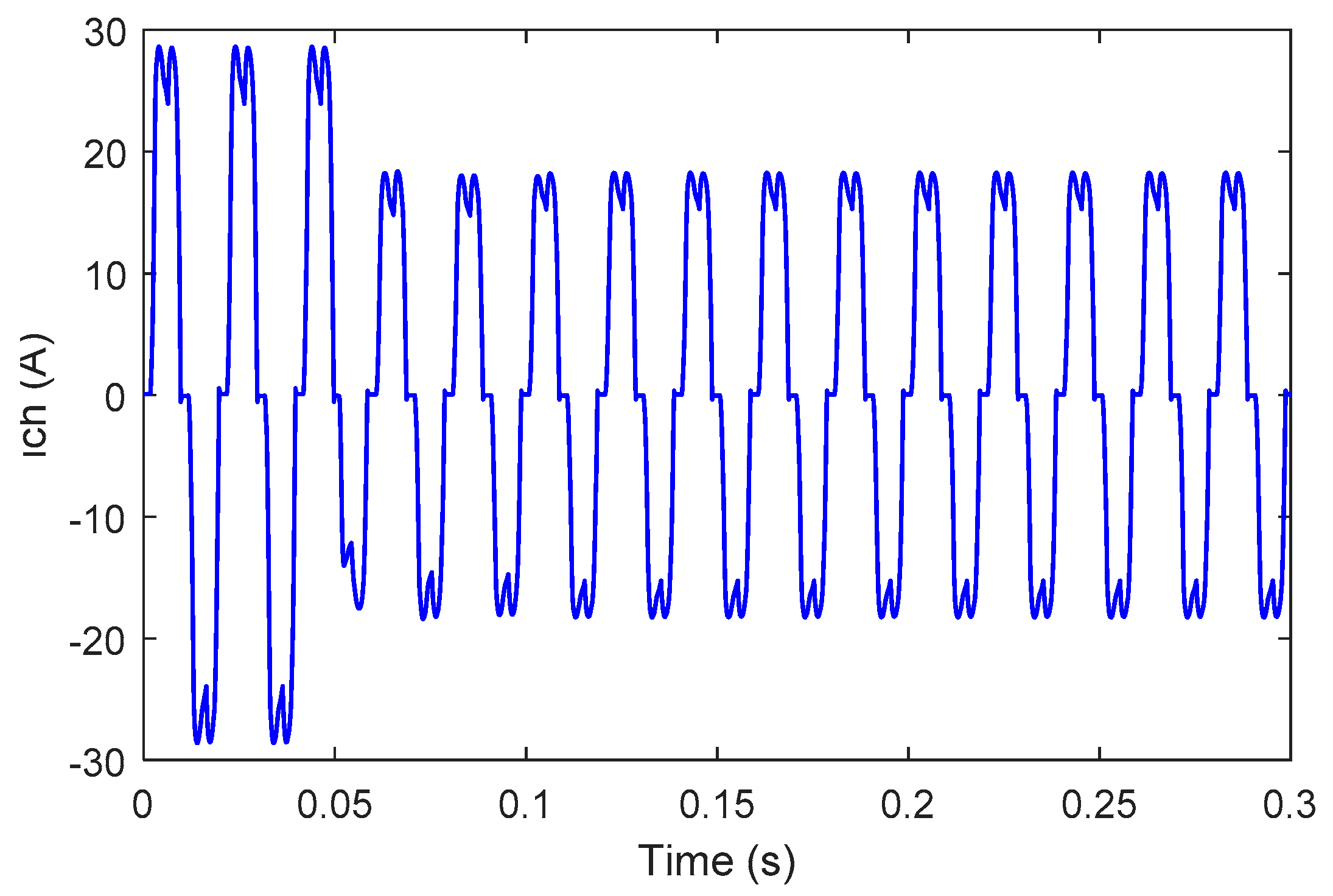
Figure 7 and Figure 8 show the charging current (for clarity, only one phase is exposed) and its harmonic spectrum. It is clearly proven that there is a significant distortion of the charging current, and that the total harmonic distortion (THD) is proportionally high (29.52%).
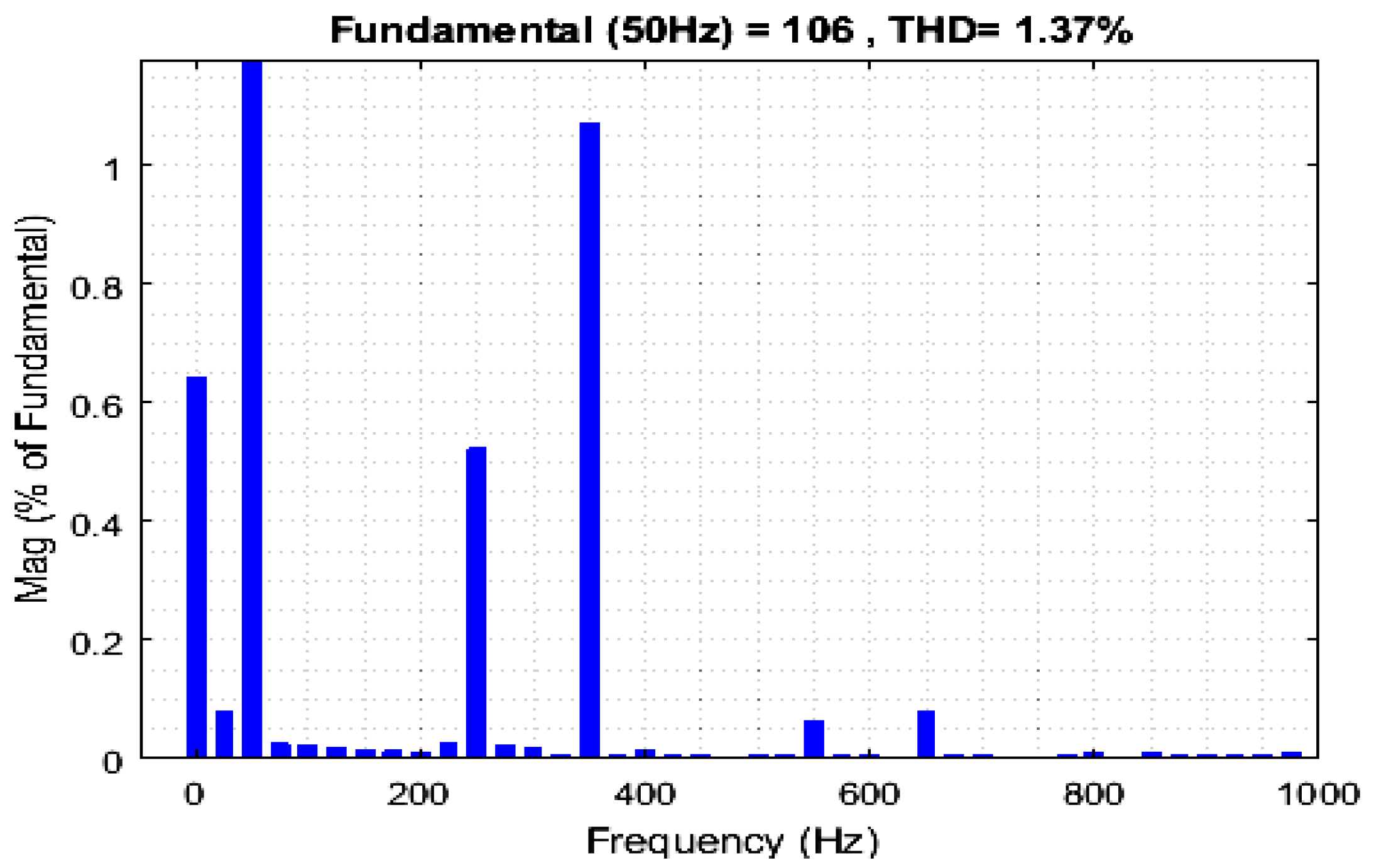
Figure 9, Figure 10 and Figure 11 present the source current spectrum, after the HAPF compensation using the PI controller, fuzzy logic controller and the proposed backstepping controller, respectively. We notice that the THDs are reduced to 2.53%, 1.81% and 1.37%, all within the standard IEEE harmonics limits of 5%, but the backstepping is significantly reduced.
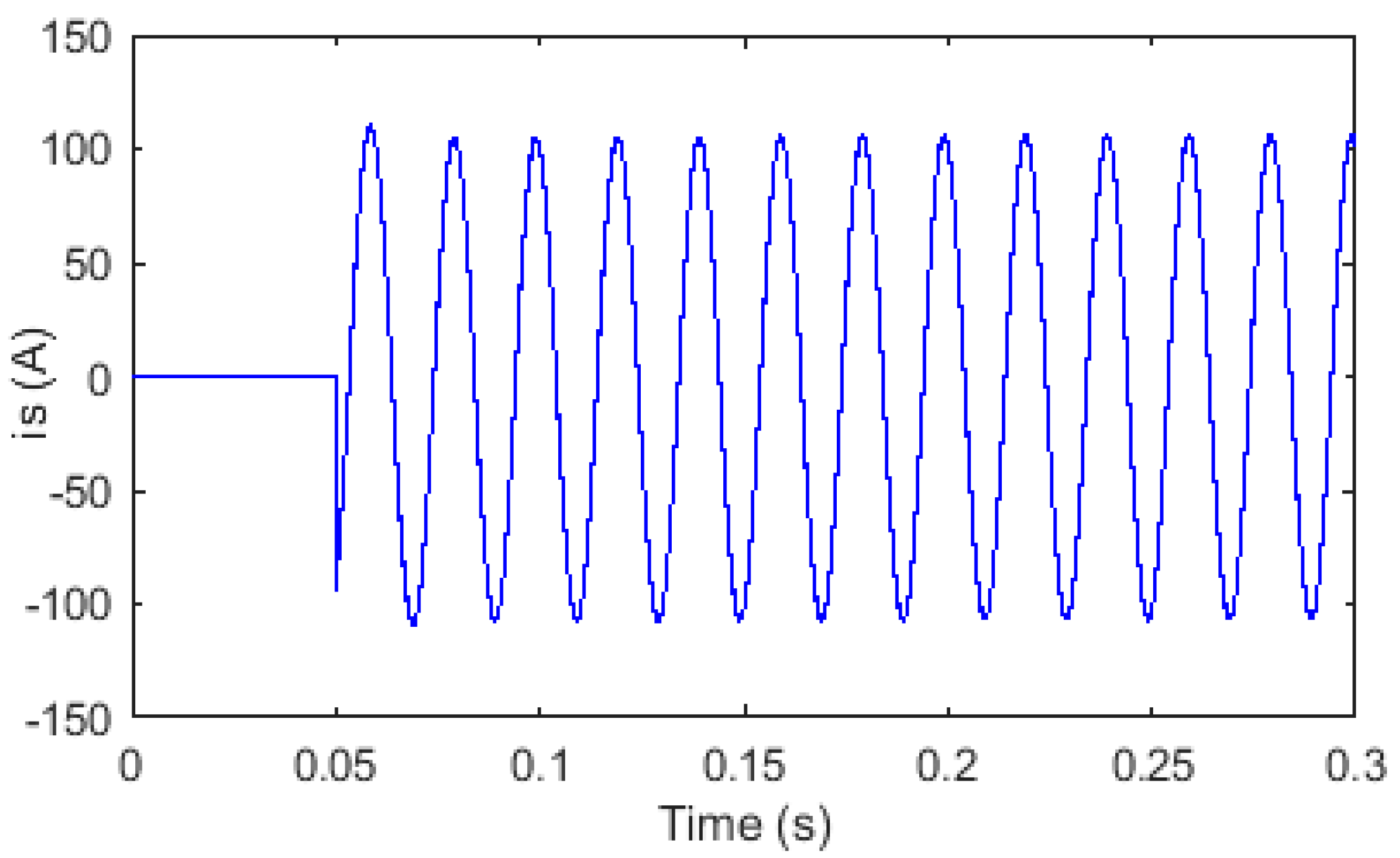
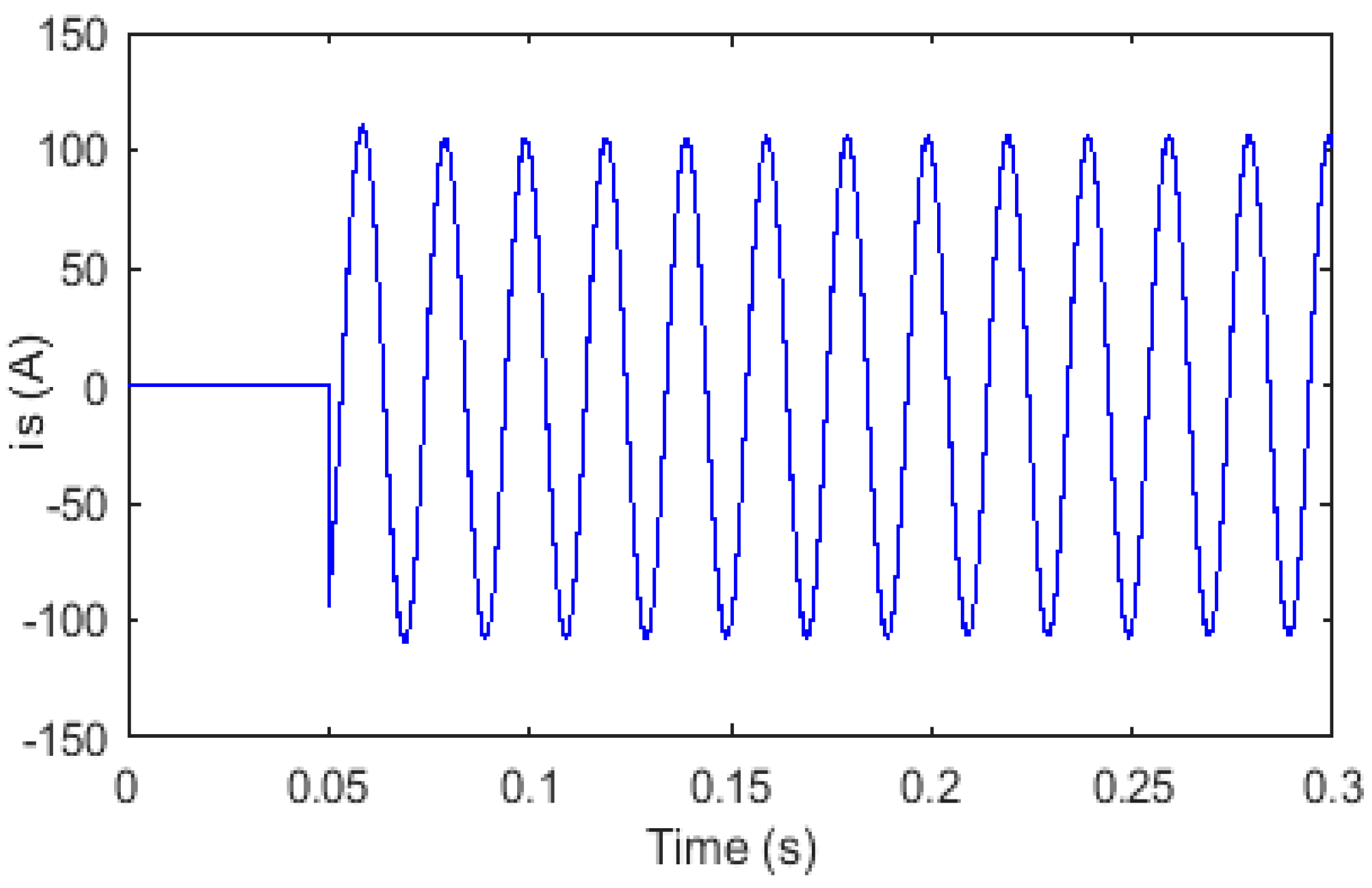
Figure 12, Figure 13 and Figure 14 illustrate the source current after filtering. It is observed that the source current with the backstepping controller is clearly sinusoidal. Also for the PI controller, and the fuzzy logic controller, the source current is almost sinusoidal but including disturbances.
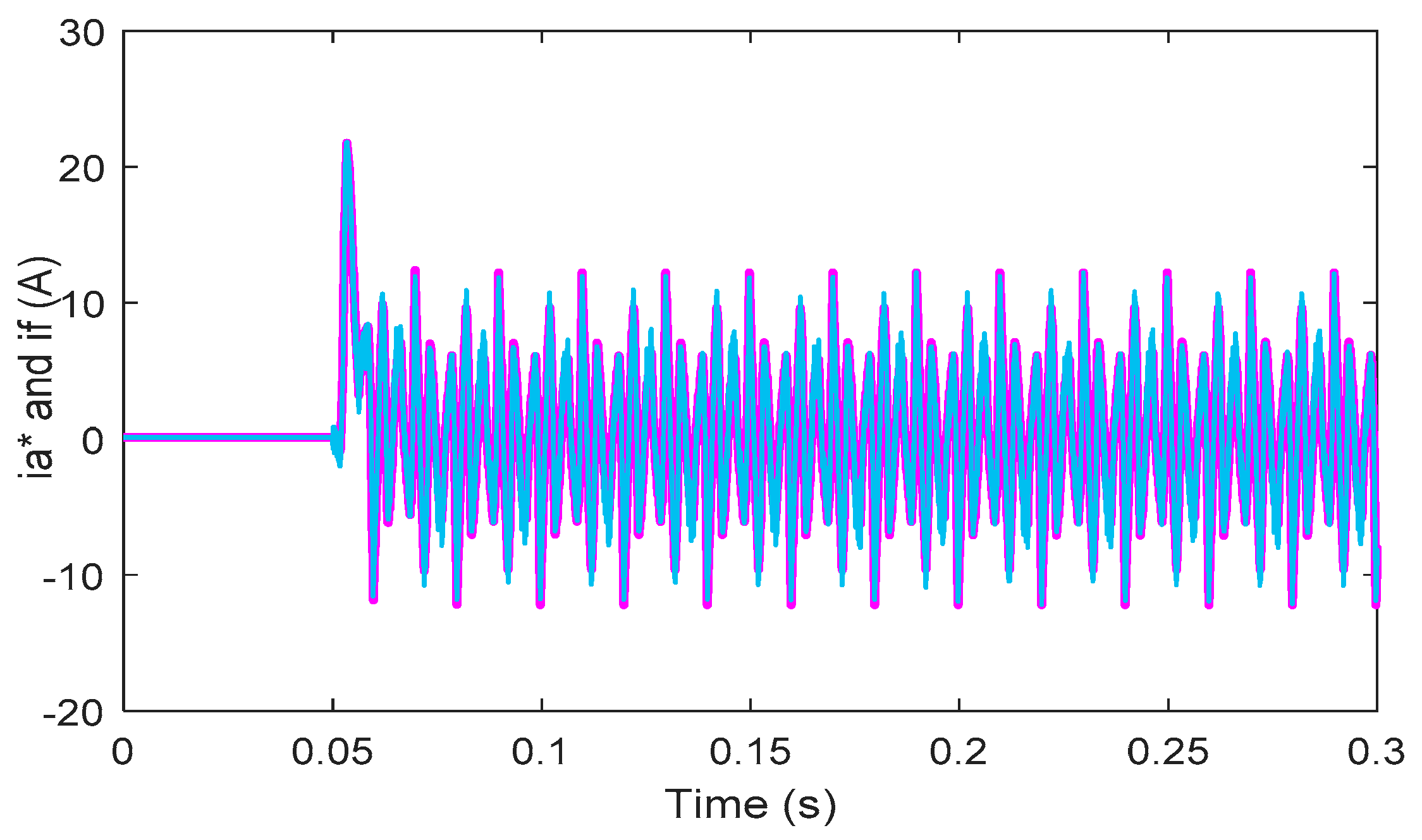
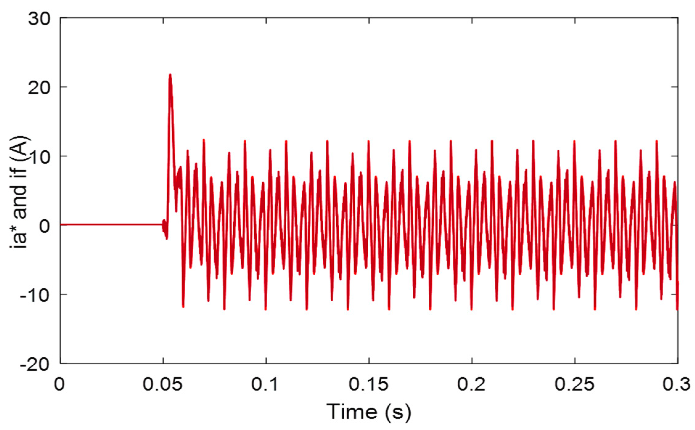
Figure 15, Figure 16 and Figure 17 present the reference current and the compensation current. It is observed that the compensation current is coincided with the reference current, and can accurately follow the reference current using the proposed backstepping controller, whereas in the case of the PI controller and the fuzzy logic controller there is a small error between the two currents. In general, this indicates that the proposed control technique can guarantee the exact monitoring of the reference current.
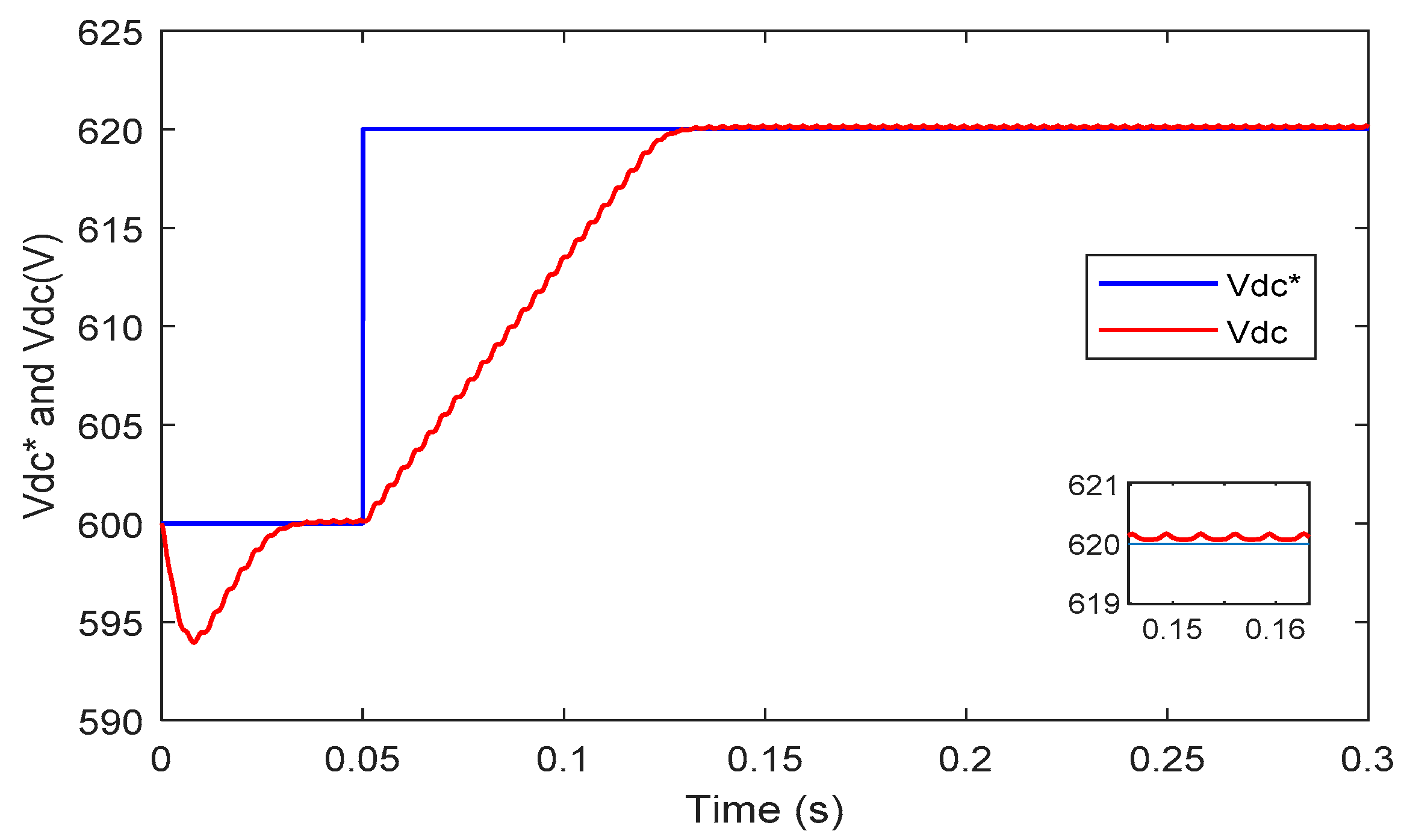
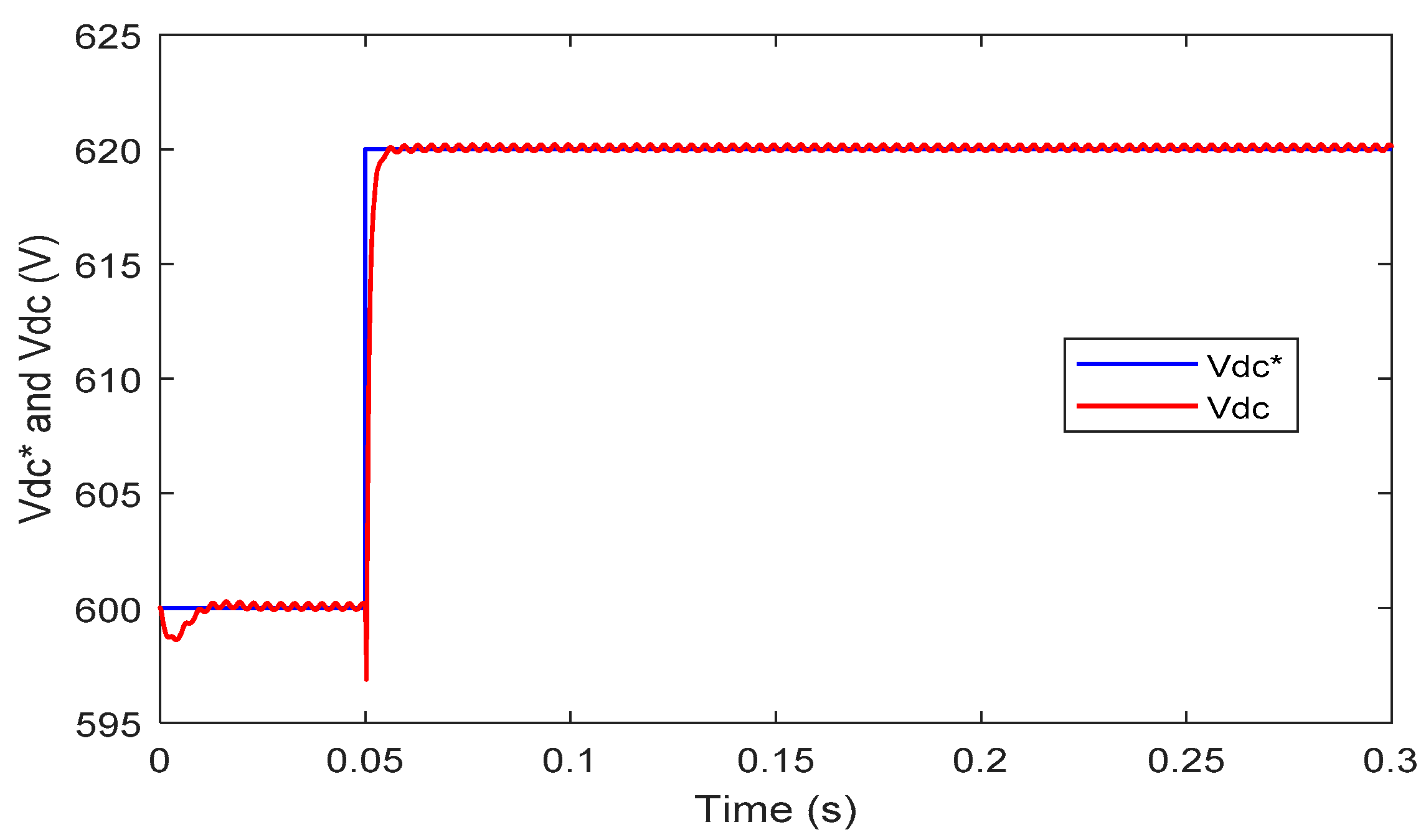
Figure 18, Figure 19 and Figure 20 indicate the DC bus voltage Vdc followed the variation of its reference with the backstepping controller at a better speed. The system is stabilized at the time t = 0.06 s, and we notice a good accuracy, but the result with the PI linear controller contains an error between the DC bus voltage Vdc and its reference which varies from 600 V to 620 V (as a ripple in the transient regime) and during the delay as shown in Figure 18. It is noted that Vdc does not follow its reference variation in the transient regime. Also, a high response time is found. The system is only stabilized at the time t = 0.135 s, which translates into a poor speed and consequently a degradation of the performance of the HAPF. Concerning the fuzzy non-linear logic controller, the system is stabilized at the time t = 0.0755 s. The delay of the voltage Vdc deviates from its reference and presents a response time at 5% lower. These make the system slower, and it contains oscillations in the permanent regime, consequently the system degrades the accuracy. The controller’s earnings are elected by test to achieve satisfactory performance. It should be noted that the THD with backstepping is significantly lower than the PI control, and fuzzy logic. We can say that the backstepping command has better control performance in terms of oscillations and response time compared to the PI and fuzzy logic controller. The response of the HAPF can be improved by using the proposed control method that achieves the desired performance.

5. Conclusions

In this document, we have implemented and investigated an HAPF with a backstepping control technique. This control technique allows to ensure the stability of the closed loop system with better speed and accuracy compared to the classical PI controller and fuzzy logic controller. It is able to maintain the THD of the current within the limits indicated by the IEEE-519 standard, and to require a desired dynamic attitude.
The simulation results obtained illustrate the high performance of the HAPF using the backstepping controller for harmonic compensation. The proposed control strategy applied to the HAPF therefore has an important theoretical impact to improve the THD in a typical way, and to strengthen the power quality of the grid, by improving the stability, speed and precision of the system. The proposed backstepping controller has an advantage that does not require a mathematical model and achieves the desired performance, but the PI controller requires a precise mathematical model, and has a significant response time, which implies a degradation of speed. Also the fuzzy logic controller has a degraded speed and precision. The HAPF can also be spread to other electronic power converter topologies.
Taking into account the above methods, the proposed controller, which is applied on a hybrid HAPF filter, is an appropriate choice for improving the quality of electrical energy in the transmission and distribution of energy. An additional experimental test bench is being developed for the realization and testing of the proposed control scheme in our laboratory.

Author Contributions

Conceptualization, N.D.; Methodology, N.D.; Software, N.D.; Validation, N.D., F.G.M. and Y.D.; Formal analysis, N.D.; Investigation, N.D.; Resources, N.D.; Data curation, N.D.; Writing—original draft preparation, N.D.; Writing—review and editing, N.D. and F.G.M.; Visualization, N.D.; Supervision, N.D., F.G.M., N.A. and Y.D.; Project administration, N.D.; Funding acquisition, F.G.M.

Funding

This research received no external funding.

Conflicts of Interest

The authors declare no conflict of interest.

References

  1. Akagi, H. Large static converters for industry and utility applications. Proc. IEEE 2001, 89, 976–983. [Google Scholar] [CrossRef]
  2. Krastev, I.; Tricoli, P.; Hillmansen, S.; Chen, M. Future of Electric Railways: Advanced Electrification Systems with Static Converters for ac Railways. IEEE Electrif. Mag. 2016, 4, 6–14. [Google Scholar] [CrossRef]
  3. Emanuel, A.E. On the assessment of harmonic pollution [of power systems]. IEEE Trans. Power Deliv. 1995, 10, 1693–1698. [Google Scholar] [CrossRef]
  4. Redl, R.; Tenti, P.; Daan van Wyk, J. Power electronics’ polluting effects. IEEE Spectr. 1997, 34, 32–39. [Google Scholar] [CrossRef]
  5. Singh, B.; Al-Haddad, K.; Chandra, A. A review of active filters for power quality improvement. IEEE Trans. Ind. Electron. 1999, 46, 960–971. [Google Scholar] [CrossRef]
  6. Rahmani, S.; Al-Haddad, K.; Kanaan, H.Y. A comparative study of shunt hybrid and shunt active power filters for single-phase applications: Simulation and experimental validation. Math. Comput. Simul. 2006, 71, 345–359. [Google Scholar] [CrossRef]
  7. Peng, F.Z.; Adams, D.J. Harmonic sources and filtering approaches-series/parallel, active/passive, and their combined power filters. In Proceedings of the Conference Record of the 1999 IEEE Industry Applications Conference: Thirty-Forth IAS Annual Meeting (Cat. No.99CH36370), Phoenix, AZ, USA, 3–7 October 1999; Volume 1, pp. 448–455. [Google Scholar]
  8. Peng, F.Z. Application issues of active power filters. IEEE Ind. Appl. Mag. 1998, 4, 21–30. [Google Scholar] [CrossRef]
  9. Kim, S.; Enjeti, P.N. A new hybrid active power filter (APF) topology. IEEE Trans. Power Electron. 2002, 17, 48–54. [Google Scholar]
  10. Graovac, D.; Katic, V.; Rufer, A. Power Quality Problems Compensation With Universal Power Quality Conditioning System. IEEE Trans. Power Deliv. 2007, 22, 968–976. [Google Scholar] [CrossRef]
  11. Routimo, M.; Salo, M.; Tuusa, H. Comparison of Voltage-Source and Current-Source Shunt Active Power Filters. IEEE Trans. Power Electron. 2007, 22, 636–643. [Google Scholar] [CrossRef]
  12. Benchaita, L.; Saadate, S.; Salem nia, A. A comparison of voltage source and current source shunt active filter by simulation and experimentation. IEEE Trans. Power Syst. 1999, 14, 642–647. [Google Scholar] [CrossRef]
  13. Ghadbane, I.; Benchouia, T.; Tahar, G. Comparative study of backstepping and Proportional Integral Controller to Compensating Current Harmonics. In Proceedings of the International Conference on Systems and Processing Information, Guelma, Algeria, 12–14 May 2013. [Google Scholar]
  14. Zelloma, L.; Rabhi, B.; Saad, S.; Benaissa, A.; Benkhoris, M.F. Fuzzy logic controller of five levels active power filter. Energy Procedia 2015, 74, 1015–1025. [Google Scholar] [CrossRef]
  15. Abdusalam, M.; Poure, P.; Saadate, S. Control of hybrid active filter without phase locked loop in the feedback et feedforward loops. In Proceedings of the ISIE, IEEE International Symposium on Industrial Electronics, Cambridge, UK, 30 June–2 July 2008. [Google Scholar]
  16. El-Habrouk, M.; Darwish, M.K.; Mehta, P. Active power filters: A review. IEE Proc. Electr. Power Appl. 2000, 147, 403. [Google Scholar] [CrossRef]
  17. Akagi, H. Control strategy and site selection of a shunt active filter for damping of harmonic propagation in power distribution systems. IEEE Trans. Power Deliv. 1997, 12, 354–363. [Google Scholar] [CrossRef] [Green Version]
  18. Marques, G.D. A comparison of active power filter control methods in unbalanced and non-sinusoidal conditions. In Proceedings of the 24th Annual Conference of the IEEE Industrial Electronics Society (Cat.No.98CH36200), IECON ’98, Aachen, Germany, 31 August–4 September 1998. [Google Scholar]
  19. Sahnouni, K.; Godfroid, H.; Berthon, A. An optimised variable structure control of a shunt active filter. In Proceedings of the IEEE International Electric Machines and Drives Conference: IEMDC’99. Proceedings (Cat. No.99EX272), Seattle, WA, USA, 9–12 May 1999; pp. 682–684. [Google Scholar]
  20. Jasim, W.; Gu, D. Integral backstepping controller for quadrotor path tracking. In Proceedings of the 2015 International Conference on Advanced Robotics (ICAR), Istanbul, Turkey, 27–31 July 2015; pp. 593–598. [Google Scholar]
  21. Ouchatti, A.; Abbou, A.; Akherraz, M.; Taouni, A. Induction motor controller using fuzzy MRAS and backstepping approach. Int. Rev. Electr. Eng. 2014, 9, 511–518. [Google Scholar]
  22. Hou, S.; Fei, J. Adaptive fuzzy backstepping control of three-phase active power filter. Control Eng. Pract. 2015, 45, 12–21. [Google Scholar] [CrossRef]
  23. Benchouia, M.T.; Ghadbane, I.; Golea, A.; Srairi, K.; Benbouzid, M.E.H. Implementation of Adaptive Fuzzy Logic and PI Controllers to Regulate the DC Bus Voltage of Shunt Active Power Filter. Appl. Soft Comput. 2015, 28, 125–131. [Google Scholar] [CrossRef]
  24. Ait Chihab, A.; Ouadi, H.; Giri, F.; El Majdoub, K. Adaptive Backstepping Control of Three-Phase Four-Wire Shunt Active Power Filters for Energy Quality improvement. J. Control Autom. Electr. Syst. 2016, 27, 144–156. [Google Scholar] [CrossRef]
  25. Campanhol, L.B.G.; da Silva, S.A.; Goedtel, A. Application of Shunt Active Power Filter for Harmonic Reduction and Reactive Power Compensation in Three-Phase Four-Wire Systems. IET Power Electron. 2014, 7, 2825–2836. [Google Scholar] [CrossRef]
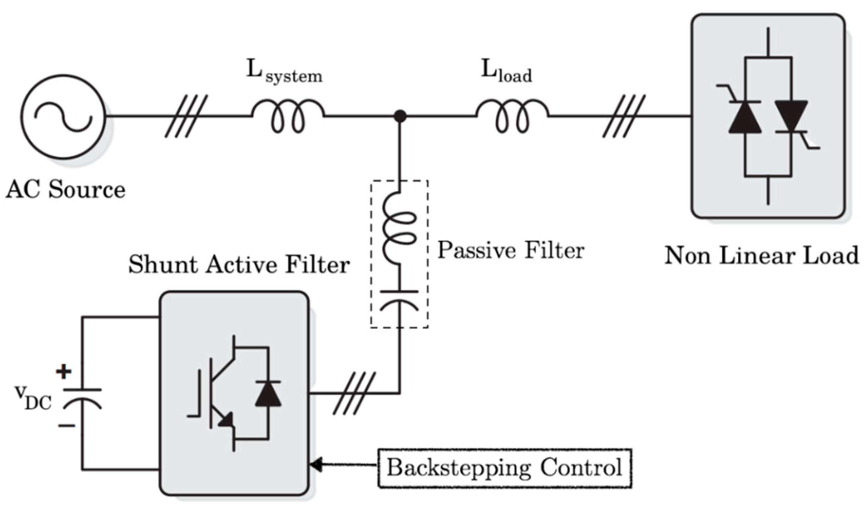
Figure 1. Topology of the proposed hybrid filter.
Symmetry 11 01161 g001
Figure 2. Principle of extraction of alternative components.
Symmetry 11 01161 g002
Figure 3. D.C. bus voltage regulation loop.
Symmetry 11 01161 g003
Figure 4. Control loop for the current injected by the filter.
Symmetry 11 01161 g004
Figure 5. Synoptic diagram of the fuzzy controller.
Symmetry 11 01161 g005
Figure 6. Realized Simulink model.
Symmetry 11 01161 g006
Figure 7. Charging current.
Symmetry 11 01161 g007
Figure 8. FFT load current analysis.
Symmetry 11 01161 g008
Figure 9. FFT analysis of the source current after filtering using the PI controller.
Symmetry 11 01161 g009
Figure 10. FFT source current analysis after filtering with fuzzy logic controller.
Symmetry 11 01161 g010
Figure 11. FFT source current analysis after filtering with backstepping controller.
Symmetry 11 01161 g011
Figure 12. Source current after filtering with the PI controller.
Symmetry 11 01161 g012
Figure 13. Source current after filtering with the Fuzzy logic controller.
Symmetry 11 01161 g013
Figure 14. Source current after filtering with the backstepping controller.
Symmetry 11 01161 g014
Figure 15. Reference and compensation current used by the PI controller.
Symmetry 11 01161 g015
Figure 16. Reference and compensation current used by the Fuzzy logic controller.
Symmetry 11 01161 g016
Figure 17. Reference and compensation current of the backstepping controller.
Symmetry 11 01161 g017
Figure 18. DC bus voltage Vdc used with PI controller.
Symmetry 11 01161 g018
Figure 19. DC bus voltage Vdc used with Fuzzy logic controller.
Symmetry 11 01161 g019
Figure 20. DC bus voltage Vdc used with backstepping controller.
Symmetry 11 01161 g020