Article

Research on Moving Target Tracking Based on FDRIG Optical Flow

1
School of Mechanical Engineering, Hubei University of Technology, Wuhan 430068, China
2
College of Mechanical Engineering, Chongqing University of Technology, Chongqing 400054, China
3
Hubei Key Lab of Manufacture Quality Engineering, Wuhan 430068, China
4
Shenzhen Zhiboyi Enterprise Management Consulting Co. Ltd., Shenzhen 518172, China
*
Author to whom correspondence should be addressed.
Symmetry 2019, 11(9), 1122; https://doi.org/10.3390/sym11091122
Submission received: 24 July 2019 / Revised: 26 August 2019 / Accepted: 28 August 2019 / Published: 4 September 2019

Abstract

:
Aiming at the problem of moving target recognition, a moving target tracking model based on FDRIG optical flow is proposed. First, the optical flow equation was analyzed from the theory of optical flow. Then, with the energy functional minimization, the FDRIG optical flow technique was proposed. Taking a road section of a university campus as an experimental section, 30 vehicle motion sequence images were considered as objects to form a vehicle motion sequence image with a complex background. The proposed FDRIG optical flow was used to calculate the vehicle motion optical flow field by the Halcon software. Comparable with the classic Horn and Schunck (HS) and Lucas and Kande (LK) optical flow algorithm, the monitoring results proved that the FDRIG optical flow was highly precise and fast when tracking a moving target. The Ettlinger Tor traffic scene was then taken as the second experimental object; FDRIG optical flow was used to analyze vehicle motion. The superior performance of the FDRIG optical flow was further verified. The whole research work shows that FDRIG optical flow has good performance and speed in tracking moving targets and can be used to monitor complex target motion information in real-time.

1. Introduction

Moving target tracking is a hotspot of computer image processing research and is widely used to monitor intelligent traffic and robot motion. At present, the main methods for tracking and calculating moving targets are the frame difference method, background subtraction, optical flow method, etc. [1,2,3,4]. Among them, the optical flow method can provide target recognition, matching and tracking [5,6,7]. It can provide the two-dimensional motion information of the moving target. Therefore, the optical flow method provides an effective measuring means for vision-based moving target analysis and behavior understanding. Since Horn and Schunck [8] proposed that optical flow could be used to estimate the motion between a pair of frames, many works have emerged to track moving objects by estimating optical flow. Mohamed et al. [9] proposed applying local derivative pattern (LDP) features to calculate the optical flow and transform images from gray space to light insensitive space in order. Bao et al. [10] presented a fast optical flow method for handling large displacement motions by exploiting the randomized propagation of self-similarity patterns and correspondence offsets.
However, some methods and models tracking moving targets are essentially based on improving HS optical flow algorithm, and few studies can perfectly eliminate the sensitive problem of HS optical flow algorithm in complex background noise. In this paper, an optical flow calculation model of FDRIG is proposed, and Halcon software is used as the development environment to realize the moving target extraction and tracking based on FDRIG optical flow. The FDRIG optical flow algorithm is applied to vehicle motion tracking through experiments. The algorithm, HS algorithm and LK algorithm are compared, which proved that FDRIG optical flow technology can extract moving target optical flow information under complex background.
The rest of the paper is organized as follows. Section 2 is related work. Section 3 will explain the theory of FDRIG optical flow. Section 4 demonstrates the experimental studies and application, and then vehicles of different scenes in two cases are analyzed. Finally, the research concludes in Section 5.

2. Related Work

Recently, lots of techniques for motion detection have been studied in the area of computer and image processing [11,12]. The motion object has been extracted from optical flow estimation for a long time. Most existing approaches are based on optical flow estimation. Rashwan et al. [13] proposed a modified optical flow algorithm to improve the stability of the system based on tensor voting filtering. Bung et al. [14] used a pyramid multi-resolution model to filter the aerated-water flow image, and then to calculate the optical flow based on the HS algorithm, thereby estimating the dynamics of the aerated-water flow. Bengtsson et al. [15] proved that the optical flow estimation can track the target motion by using a camera to alternately capture the multi-frame sequence image of the moving targets. Lan et al. [16] proposed a target extraction and tracking method based on sparse optical flow, aiming at the problem of moving object tracking on condition of simultaneous motion between the background and camera, this method significantly reduced the false detection rate of target feature points and is suitable for slow-motion scenes. Qin et al. [17] proposed an optimized HS optical flow algorithm based on motion estimation. The ROI was determined by detecting HARRIS corners in the image and combining with block motion estimation. Kumaran et al. [18] proposed a new approach of traffic flow-based intelligent signal timing by temporally clustering optical flow features of moving vehicles using temporal unknown incremental clustering (TUIC) model. The model designed a new inference scheme that works approximately 5-times faster as compared to the one originally proposed in TUIC in a dense traffic intersection. The new inference scheme can trace clusters representing moving objects that may be occluded while being tracked. A new method named laser speckle optical flow imaging (LSOFI) was introduced by Aminfar et al. [19], this method used the optical flow algorithms to calculate the apparent motion of laser speckle patterns. The differences in the apparent motion of speckle patterns were used to identify the blood vessels from surrounding tissue. LSOFI has better spatial and temporal resolution compared to LSCI. Zhang et al. [20] proposed an effective motion object detection method based on optical flow estimation, which the characterized was that the complete boundary of the motion object can be extracted from the combination of the optimized horizontal flow with the optimized vertical flow. Sengar et al. [21] have efficiently detected the moving objects by computing the optical flow between three consecutive frames. The algorithm combines both the optical flow components to compute the gross optical flow, moving objects are detected using morphological operation on the equalized output. But the optical flow of motion targets can not be extracted accurately in the above methods. In this paper, we will in-depth study tracking motion objects using a novel optical flow algorithm.

3. Principle and Implementation of FDRIG Optical Flow

In this section, we mainly introduce the theory of optical flow and proposed the FDRIG optical flow method and the main steps of the proposed algorithm.

3.1. Theory of Optical Flow

The concept of optical flow is proposed by Gison. It is the instantaneous change of the position of the object point in the image [22]. The motion of the object can be described by the motion field composed of the motion vector of points in the image. The optical flow field is the projection of the motion field of the two-dimensional image. It contains the motion target information: motion or velocity field, part of optical features, and the projection of the image. The core is to solve the optical flow of the moving target, i.e., the velocity. The image projected of the camera is continuously changing during the motion, so the optical gradation equation can be solved by assuming the instantaneous gray is invariant.
Optical flow describes the movement of a space object on the image at two-dimensional motion. As shown in Figure 1, O is the optical center of the camera, and the camera coordinate system is OXYZ. Setting P as an object point in three-dimensional space, at time t, (X1, Y1, Z1) is the coordinates of P in OXYZ. At time t + δ t , P moves to P ( X 1 + δ x , Y 1 + δ y , Z 1 + δ z ) , and then the image projection point of image plane is p , which the corresponding image coordinate is ( x + u , y + v ) , and the grayscale is I ( x + u , y + v , t + δ t ) . So when P moves from coordinate (X1, Y1, Z1) to coordinate in P ( X 1 + δ x , Y 1 + δ y , Z 1 + δ z ) three-dimensional space, p moves from coordinate (x, y) to coordinate ( x + u , y + v ) in two-dimensional image plane, as shown in Figure 1.
Let the gray of point p (x, y) on the image be I (x, y, t) at time t, then the optical flow w = (u, v) at the horizontal and vertical movement component u (x, y) and v (x, y) are:
u = d x d t     v = d y d t
After the time interval d t , and the corresponding point gray is I ( x + d t , y + d y , t + d t ) . When the time interval t approaches 0, the gray does not change, there are:
I ( x , y , t ) = I ( x + d t , y + d y , t + d t )
Expanded by Taylor, the basic optical flow constraint equation is:
I t + I x u + I y v = 0
In order to solve the optical flow w = (u, v), a constraint must be added to the formula (3) to form different optical flow algorithms. There are mainly block matching algorithms, Horn and Schunck (HS) algorithms and Lucas and Kande (LK) algorithms. However, the optical flow block matching algorithm determines the offset of feature matching, and the calculation amount is large, and the matching block size has a great influence on the optical flow calculation, and the local information is easily missed. The HS algorithm assumes that the rate of change of velocity is zero using a global smoothing constraint, but the condition is difficult to fully realize, and the algorithm removes important feature parameters such as contour and shape of the object. The LK algorithm is a local smoothing algorithm, suitable for small image motion or slow speed, but it is helpless for tracking large moving targets.

3.2. FDRIG Optical Flow Algorithm

Because of the current deficiencies of several optical flow algorithms, this paper uses FDRIG optical flow to track moving targets. Featuring flow drive-based, robustness and constant gradient, the FDRIG optical flow is based on the warping algorithm proposed by Brox, Bruth, and Papernberg [23]. So we also defined the FDRIG optical flow algorithm as the warping algorithm. The formation of optical flow is estimated by the energy minimum function. Firstly, the FDRIG optical flow is smoothed by Gaussian filtering, with the standard deviation as the initial value, and the optical flow variation is calculated as the minimum suitable energy function. Which is:
E ( w ) = E D ( w ) + a l p h a * E S ( w )
where w = (u, v) is the calculated optical flow field. E D ( w ) denotes the conservation term energy function, which is based on the continuous image target feature constant, that is, the gray level is unchanged or the gray value space derivative is steady. E S ( w ) expresses smoothness; a l p h a is the smoothing factor, which determined the smoothness weight.
Equation (4) can be expressed as:
E ( w ) = E D ( w ) + a l p h a * E S ( w ) = [ ( I x u + I y v + I t ) 2 + a l p h a * ( u x 2 + u y 2 + v x 2 + v y 2 ) ] d x d y = [ ( I x u + I y v + I t ) 2 + a l p h a * ( u 2 + v 2 ) ] d x d y
where I x = I x , I y = I y , I t = I t denote the partial derivative of the image gray value in the spatial domain x, y and the time domain, respectively. u 2 = u x 2 + u y 2 , v 2 = v x 2 + v y 2 is respectively the gradient values of the pixel points in the u and the v domain space.
The FDRIG optical flow is to minimize energy function E ( w ) to estimate the optical flow based on warping algorithm. And the optical flow is extracted by calculating the minimum value of the formula (5). The partial derivative of the optical component u, v is obtained, respectively. Let the derivative is 0, and the optical flow w = (u, v) is solved.
The FDRIG optical flow computing steps are as follows:
Step 1. Acquire the original two sequence images. The optical flow represents motion information of the two images.
Step 2. Preprocess image, and convert a color motion sequence image into a monochrome gray image. This step is carried out in Matlab software.
Step 3. Use Gaussian filtering to smooth the image sequence and eliminate noise. The Gaussian filter calculation method can be referred to in the literature [24].
Step 4. Solve the partial derivative of the optical component using Equations (4) and (5), and estimate the optical flow w = (u, v) of the target moving image, then to calculate the optical flow field, and obtain the target motion information.

4. Experimental Studies and Discuss

In this section, we studied the experiment that to estimate the motion of the target based on FDRIG optical flow and testified the advantages of FDRIG optical flow proposed in the paper. The important results and discussion were analyzed in the section.

4.1. Experiment 1 on one Vehicle

4.1.1. Description of the Experimental Process

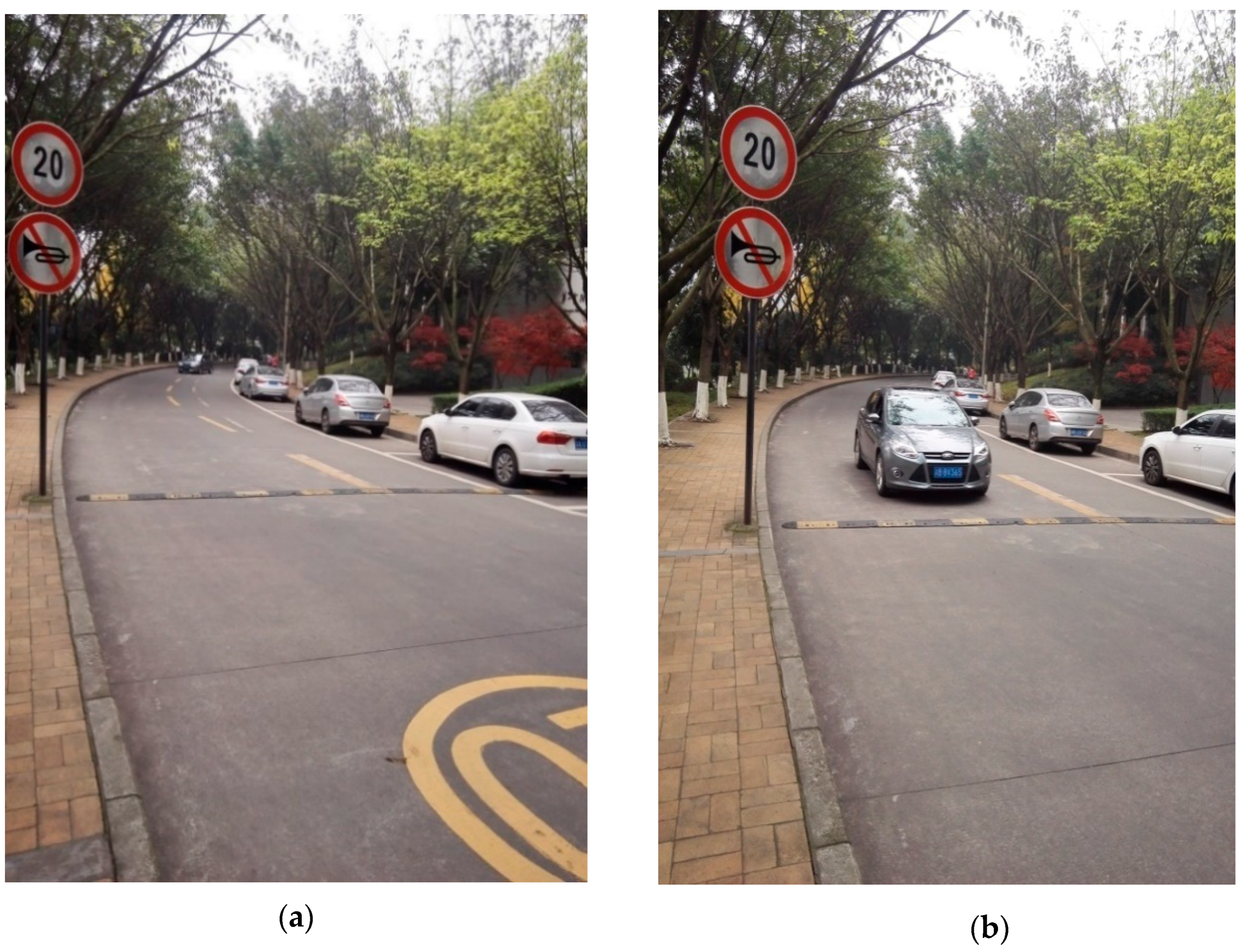
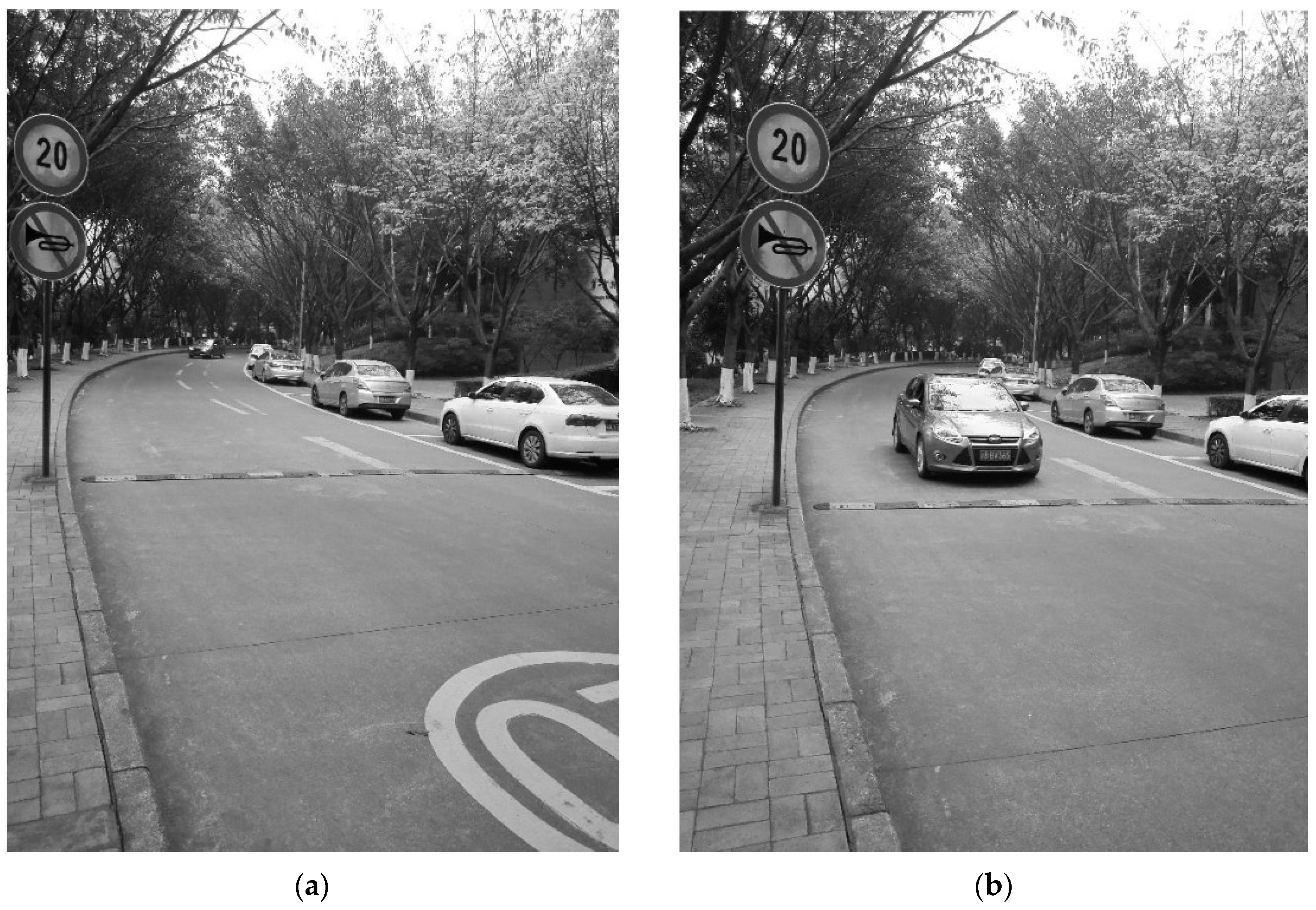
In order to estimate the motion of the target based on FDRIG optical flow, we used a tripod fixed mobile phone to shoot images. The height of the tripod is 150 cm, and the mobile phone brand is Huawei Honor 6 Plus. The section for the experiment is 150 m from the exit of a tunnel named Shijimen on the campus of a university. A moving target is tracked by computing FDRIG optical of sequences images of the silver color vehicle motion with speed is 20 km/h. The time interval of the sequence images is 1 second, and the experimental sequence images are 30 frames. Sequential images were acquired at 10:00 A.M, 21 May 2018. Figure 2a,b are the first and last frame images of vehicle motion, respectively. The experimental computer was the Vostro 3900-R6308 Dell desktop. The programming environment was Windows 7 and the programming language was Halcon. Figure 3a,b are gray images of the first frame and the last frame of the vehicle motion using Matlab software. In the sequential images of vehicle motion, the background has both trees and roads, street signs, and other static or moving vehicles with complex background. So the experiment tested vehicle moving tracking with a complex background, which can effectively verify the proposed FDRIG optical flow.

4.1.2. Parameter Setting in Halcon Software Based on FDRIG Optical Flow

Halcon software has good performance for machine vision. Researchers can utilize Halcon software for secondary development, precision measurement, 3D camera calibration, barcode recognition, visual inspection, etc. [25,26]. Based on the further development of Halcon and setting the parameters to track the vehicles in the experiment, this paper completed the moving target tracking based on FDRIG optical flow algorithm.
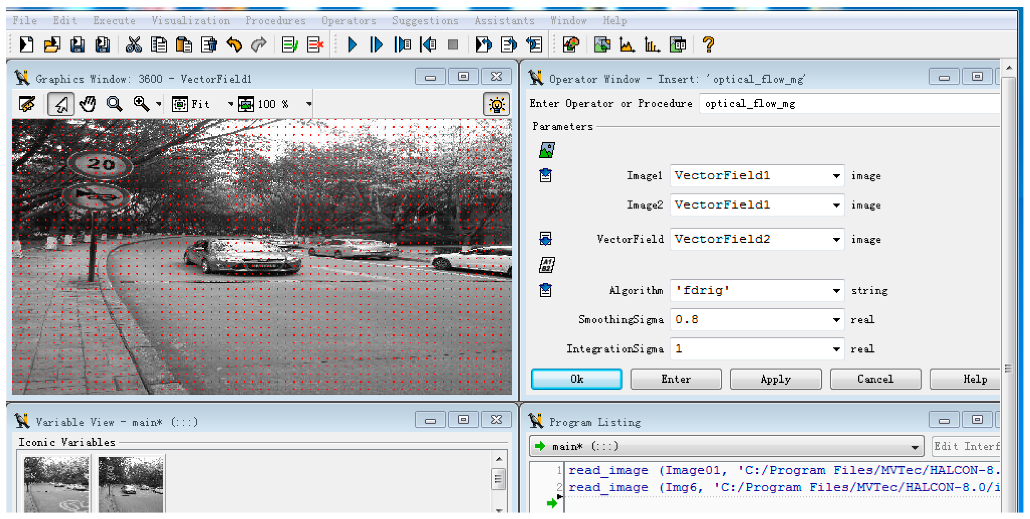
Figure 4 shows an interface that calculates and process moving vehicles by FTRIG optical flow in Halcon program.
The FDRIG optical flow needed to calculate the optical flow fields of two adjacent pictures: Image1 and Image2. In the Halcon program, Image1 and Image2 were consecutive images of the input to two monochromatic image sequences. VectorField was the output of optical flow. The parameters were set in the experiment: initial value of the Gaussian smooth initial deviation was 0.8, initial value of the integral filter deviation was 20, smoothness was 7, gradient constant coefficient relative to gray value constancy was 5, and other parameters were set to default.

4.1.3. Results and Discussion

The 30 sequence images obtained in the experiment were used as test samples to estimate vehicle motion vector by FDRIG optical flow. The current vehicle motion vector estimated by HS and LK optical flow algorithm was used for comparison to test the superiority of the FDRIG optical flow algorithm. Figure 5a,b show the optical flow field and vehicle motion tracking vector of the HS algorithm. Figure 6a,b are the optical flow field and vehicle motion estimation vector of LK algorithm, respectively, and Figure 7a,b are the optical flow field and vehicle motion estimation vector of FDRIG algorithm, respectively.
It can be seen from the comparison of the above several optical flow fields that range of the estimated optical flow field of the vehicle motion by HS algorithm is too large. The optical flow field not only contains the vehicle motion tracking, but also the road in front of the vehicle. Two optical flow fields were formed, as shown by the yellow color concentrated part in Figure 5a, and in the green area of Figure 5b. There are some difficulties in estimating the moving target of complex background images. On the contrary, the area where the two optical flow field estimated by the LK algorithm in Figure 6a,b are very small, and the first optical flow field is located in the left window and the tire area of the vehicle, and the second optical flow field is about 10 cm from the right edge of the license plate. Moreover, the two optical flows are too intermittent to completely track vehicle motion. So the experiment explains that LK algorithm is not suitable for clear and perfect tracking of vehicles with a certain speed and large motion and it is not fit for tracking targets in complex scenes with noise.
Figure 7a,b are the optical flow fields calculated by the FDRIG algorithm proposed in this paper. It can be seen that the optical flow field was concentrated around the front of the vehicle, and the optical flow motion region was integrated enveloping the vehicle. In addition, the tracking precision of vehicle motion is better than HS or LK algorithm. Accordingly, it is proved that the FDRIG optical flow can accurately trace moving vehicle with a certain speed and complex background in the natural environment.
The time of three optical flows (i.e., FDRIG, HS, and LK algorithm) for the vehicle’s optical flow field in the same experimental environment is shown in Table 1. We can see that the longest time to compute the flow field is 4s with HS algorithm, in contrast to 0.5 s with the FDRIG optical flow.
It is seen that the longest time to compute optical flow field is 4 s with HS algorithm with HS and LK algorithm. In contrast, the shortest calculated time is 0.5 s with FDRIG optical flow. As a global smoothing algorithm, HS optical flow has a large computational complexity, and its optical flow field calculation time is longer than that of LK and FDRIG local smoothing algorithm, Therefore, HS optical flow is not suitable for real-time dynamic tracking of moving targets. Being able to do dynamic real-time moving target tracking, both FDRIG and LK optical flow algorithms can be used to do real-time tracking and monitoring of vehicles at traffic intersections.
To evaluate the accuracy of the FDRIG algorithm, the average angular error (AAE) and the standard deviation (SD) indicator were introduced [27]. The angular error calculation formula is
A E = cos 1 ( 1.0 + u × u G T + v × v G T 1.0 + u 2 + v 2 1.0 + u G T 2 + v G T 2 )
( u , v ) refers to calculated value of optical flow, and ( u G T , v G T ) is true value of light flow.
The standard deviation of the average angular error and the angular error are respectively calculated as
A A E = 1 N N ( A E )
S D = 1 N 1 N ( A E A A E ) 2
Table 2 shows the comparison results of the HS, LK, Weickert, and FDRIG optical flow algorithm, respectively.
It can be seen from the results in Table 2 that the performance on the average angular error and standard deviation of the FDRIG optical flow is smaller than other optical flow algorithms, and the angular error is less than half of other optical flow algorithms. This also illustrates that the FDRIG algorithm based on the assumption of flow drive and gray stability can well handle the brightness change problem caused by vehicle motion in this experimental scene.

4.2. Analysis and Discussion of Experiment 2 on Multi-Vehicles Motion

The simulation scenario of Experiment 1 is the motion situation of a single-vehicle. To further study the parallel tracking characteristics of multi-vehicle motion, experiment 2 used real image data in an Ettlinger Tor traffic scene for analysis. The Ettlinger Tor traffic scene was composed of 50 frames of 512 × 512 pixels. The optical flow field calculated by the FDRIG method is shown in Figure 8.
Results of Figure 8 indicate that tracking vehicle motion by FDRIG optical flow is very clear and there is no image artifact when tracking interleaved and complex vehicles in all frames of images. In Figure 8a, the movement state of the pedestrian crossing the road is clearly tracked when the traffic light turns green, and the walking state of the pedestrian on the sidewalk is also preferably displayed in the optical flow field in Figure 8b,c. In addition, the boundary of four frame images selected from 50-frame traffic scene images are relatively sharp and clear. The waiting vehicles were not tracked by FDRIG optical flow, which indicates that these vehicles were static when the traffic lights turned red. In contrast, vehicles and pedestrians in motion can be tracked and identified by optical flow, marked as moving state. So it can be verified from four frame images that FDRIG optical flow algorithm can directly segment and recognize moving image quickly and accurately through threshold settings.

5. Conclusions

The optical flow technology can track the moving targets. Experimental results show that the proposed FDRIG algorithm outperforms the traditional optical flow algorithms, such as HS and LK, and can monitor the moving vehicle in real-time and dynamically under the condition of a complex background. Another important point is to study the tracking of vehicle motion in a complex scene with multiple vehicles, pedestrians, and alternate stationary and moving scenes. The FDIRG optical flow can accurately identify multiple moving targets, which can be used for vehicle tracking in real-time at traffic intersections and realize intelligent traffic monitoring with high accuracy and efficiency. In future works, we hope to study the performance of the optical flow algorithm in bad environments, such as rain and fog, and to discuss the tracking and recognition of moving objects with six degrees of freedom, such as rotating motion, so as to expand the application scenarios of FDRIG optical flow.

Author Contributions

Conceptualization, G.L.X. and W.C.L.; methodology, G.L.X.; software, G.L.X. and W.C.L.; validation, G.L.X. and W.C.L.; formal analysis, G.L.X.; investigation, G.L.X.; resources, G.L.X.; data curation, G.L.X.; writing—original draft preparation, G.L.X. and W.C.L.; writing—review and editing, G.L.X.; visualization, G.L.X. and W.C.L.; supervision, G.L.X. and W.C.L.; project administration, G.L.X.; funding acquisition, G.L.X.

Funding

This research is funded by Ministry of Education of Humanities and Social Science Research Program of China (Grant No. 15YJCZH049), Chongqing Research Program of Basic Research and Frontier Technology (Grant No.cstc2016jcyjA0385, and cstc2017jcyjAX0343), the Doctoral Scientific Research Start-up Foundation of Hubei University of Technology(Grant No.BSQD2019004), and the Open Program of Academic Team of Advanced Manufacturing Technology and Equipment & Inter Disciplinary Research Institute of Product Quality Engineering, HBUT.

Acknowledgments

The authors would like to thank the editors and the anonymous referees for their careful review and valuable suggestions that improved the quality of this paper.

Conflicts of Interest

The authors declare no conflict of interest.

References

  1. Garcia, J.; Gardel, A.; Bravo, I.; Lazaro, J.L.; Martinez, M.; Rodriguez, D. Directional People Counter Based on Head Tracking. IEEE Trans. Ind. Electron. 2013, 60, 3991–4000. [Google Scholar] [CrossRef]
  2. Muddamsetty, S.M.; Sidibé, D.; Trémeau, A.; Mériaudeau, F. Salient objects detection in dynamic scenes using color and texture features. Multimed. Tools Appl. 2017, 77, 5461–5474. [Google Scholar] [CrossRef] [Green Version]
  3. Shi, X.B.; Wang, M.; Zhang, D.Y.; Huang, X.S. An Approach for Moving Object Detection Using Continuing Tracking Optical Flow. J. Chin. Comput. Syst. 2014, 35, 643–647. [Google Scholar]
  4. Jazayeri, A.; Cai, H.; Zheng, J.Y.; Tuceryan, M. Vehicle Detection and Tracking in Car Video Based on Motion Model. IEEE Trans. Intell. Transp. Syst. 2011, 12, 583–595. [Google Scholar] [CrossRef]
  5. Pijnacker Hordijk, B.J.; Scheper, K.Y.; De Croon, G.C. Vertical landing for micro air vehicles using event-based optical flow. J. Field Robot. 2018, 35, 69–90. [Google Scholar] [CrossRef]
  6. Guan, W.; Chen, X.; Huang, M.; Liu, Z.; Wu, Y.; Chen, Y.; Wu, X. High-Speed Robust Dynamic Positioning and Tracking Method Based on Visual Visible Light Communication Using Optical Flow Detection and Bayesian Forecast. IEEE Photonics J. 2018, 10, 1–22. [Google Scholar] [CrossRef]
  7. Schuster, T.; Weickert, J. On the Application of Projection Methods for Computing Optical Flow Fields. Inverse Probl. Imaging 2017, 1, 673–690. [Google Scholar]
  8. Horn, B.K.; Schunck, B.G. Determining optical flow. Artif. Intell. 1981, 17, 185–203. [Google Scholar] [CrossRef] [Green Version]
  9. Mohamed, M.A.; Rashwan, H.A.; Mertsching, B.; García, M.A.; Puig, D. Illumination-Robust Optical Flow Using a Local Directional Pattern. IEEE Trans. Circuits Syst. Video Technol. 2014, 24, 1499–1508. [Google Scholar] [CrossRef]
  10. Bao, L.; Yang, Q.; Jin, H. Fast Edge-Preserving PatchMatch for Large Displacement Optical Flow. IEEE Trans. Image Process. 2014, 23, 4996–5006. [Google Scholar] [CrossRef]
  11. Muhammad, K.; Hamza, R.; Ahmad, J.; Lloret, J.; Wang, H.; Baik, S.W.; Wang, H.H.G. Secure Surveillance Framework for IoT Systems Using Probabilistic Image Encryption. IEEE Trans. Ind. Inform. 2018, 14, 3679–3689. [Google Scholar] [CrossRef]
  12. Zhong, Y.; Ma, A.; Ong, Y.S.; Zhu, Z.; Zhang, L. Computational intelligence in optical remote sensing image processing. Appl. Soft Comput. 2018, 64, 75–93. [Google Scholar] [CrossRef]
  13. Rashwan, H.A.; Puig, D.; Garcia, M.A. Improving the robustness of variational optical flow through tensor voting. Comput. Vis. Image Underst. 2012, 116, 953–966. [Google Scholar] [CrossRef]
  14. Bung, D.B.; Valero, D. Optical flow estimation in aerated flows. J. Hydraul. Res. 2016, 54, 575–580. [Google Scholar] [CrossRef]
  15. Bengtsson, T.; McKelvey, T.; Lindström, K. Optical flow estimation on image sequences with differently exposed frames. Opt. Eng. 2015, 54, 093103. [Google Scholar] [CrossRef]
  16. Lan, H.; Zhou, W.; Qi, Y. Sparse optical flow target extraction and tracking in dynamic backgrounds. J. Image Graph. 2016, 21, 771–780. [Google Scholar]
  17. Qin, X.-B.; Chai, Z. Optical flow algorithm based on optimized motion estimation. J. Sichuan Univ. 2014, 51, 475–479. [Google Scholar]
  18. Kumaran, S.K.; Mohapatra, S.; Dogra, D.P.; Roy, P.P.; Kim, B.G. Computer vision-guided intelligent traffic signaling for isolated intersections. Expert Syst. Appl. 2019, 134, 267–278. [Google Scholar] [CrossRef]
  19. Aminfar, A.H.; Davoodzadeh, N.; Aguilar, G. Application of optical flow algorithms to laser speckle imaging. Microvasc. Res. 2019, 122, 52–59. [Google Scholar] [CrossRef]
  20. Zhang, Y.; Zheng, J.; Zhang, C.; Li, B. An effective motion object detection method using optical flow estimation under a moving camera. J. Vis. Commun. Image Represent. 2018, 55, 215–228. [Google Scholar] [CrossRef]
  21. Sengar, S.S.; Mukhopadhyay, S. Detection of moving objects based on enhancement of optical flow. Optik 2017, 145, 130–141. [Google Scholar] [CrossRef]
  22. Sun, D.; Sudderth, E.B.; Black, M.J. Layered image motion with explicit occlusions, temporal consistency, and depth ordering. Adv. Neural Inf. Process. Syst. 2010, 10, 2226–2234. [Google Scholar]
  23. Brox, T.; Bruhn, A.; Papenberg, N.; Weickert, J. High accuracy optical flow estimation based on a theory for warping. In Proceedings of the 8th European Conference on Computer Vision, Prague, Czech Republic, 11–14 May 2004. [Google Scholar]
  24. Qian, X.; Guo, L.; Yu, B. Adaptive Gaussian filter based on object scale. Comput. Eng. Appl. 2010, 46, 14–20. [Google Scholar]
  25. Wang, W. Design of gear defect detection system based on the Halcon. J. Mech. Transm. 2014, 38, 60–63. [Google Scholar]
  26. Zhang, Q.; Shen, H.; Shen, M. The Quality Detection of the Non-Mark Printing Image Based on Halcon. J. Shantou Univ. 2011, 26, 63–68. [Google Scholar]
  27. Zhang, Q.; Zhang, N. An improved optical flow algorithm based on global minimum energy function. J. North. Univ. China 2014, 35, 330–336. [Google Scholar]
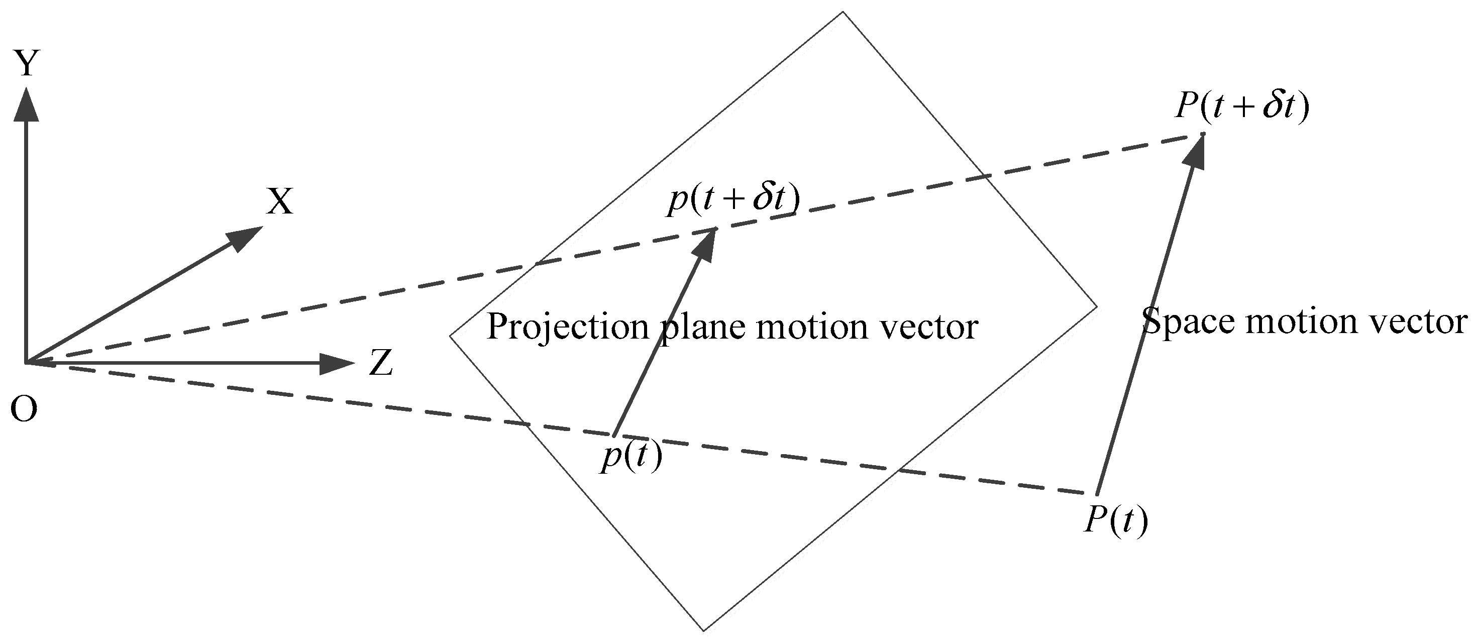
Figure 1. Optical flow diagram.
Symmetry 11 01122 g001
Figure 2. Vehicle motion images. (a) The first frame. (b) The last frame.
Symmetry 11 01122 g002
Figure 3. Vehicle motion grayscale. (a) The first frame gray image. (b) The last frame gray image.
Symmetry 11 01122 g003
Figure 4. FDRIG optical flow interface in Halcon.
Symmetry 11 01122 g004
Figure 5. HS algorithm vehicle motion tracking. (a) Horn and Schunck (HS) optical flow field. (b) HS vehicle motion estimation vector.
Symmetry 11 01122 g005
Figure 6. LK algorithm vehicle motion tracking. (a) Lucas and Kande (LK) optical flow field. (b) LK vehicle motion estimation vector.
Symmetry 11 01122 g006
Figure 7. FDRIG algorithm vehicle motion tracking. (a) FDRIG optical flow field. (b) FDRIG vehicle motion estimation vector.
Symmetry 11 01122 g007
Figure 8. Ettlinger Tor traffic scene FDRIG optical flow field. (a) Traffic scene 1 Optical flow field. (b) Traffic scene 2 Optical flow field. (c) Traffic Scene 3 Optical Flow Field. (d) Traffic Scene 4 Optical Flow Field.
Symmetry 11 01122 g008aSymmetry 11 01122 g008b
Table 1. Comparison of time for calculating optical flow field of three algorithms.
Optical flow algorithmHS Optical FlowLK Optical FlowFDRIG Optical Flow
Time of optical flow field (s)410.5
Table 2. Accuracy results of different optical flow algorithm.
Optical Flow AlgorithmAAESD
HS optical flow algorithm10.58°16.20°
LK optical flow algorithm7.19°11.23°
Weickert algorithm6.15°8.86°
FDRIG optical flow algorithm2.26°5.31°