Abstract
The Lagrangian meshfree particle-based method has advantages in solving fluid dynamics problems with complex or time-evolving boundaries for a single phase or multiple phases. A pure Lagrangian meshfree particle method based on a generalized finite difference (GFD) scheme is proposed to simulate time-dependent weakly compressible viscous flow. The flow is described with Lagrangian particles, and the partial differential terms in the Navier-Stokes equations are represented as the solution of a symmetric system of linear equations through a GFD scheme. In solving the particle-based symmetric equations, the numerical method only needs the kernel function itself instead of using its gradient, i.e., the approach is a kernel gradient free (KGF) method, which avoids using artificial parameters in solving for the viscous term and reduces the limitations of using the kernel function. Moreover, the order of Taylor series expansion can be easily improved in the meshless algorithm. In this paper, the particle method is validated with several test cases, and the convergence, accuracy, and different kernel functions are evaluated.
1. Introduction
Problems of weakly compressible flows have attracted much attention in aerospace and oceanic applications, such as wind engineering problems, turbine flow, blood flow, and water wave motion. Accurate predictions of such flows are important in computational fluid dynamics. For fluids at low Mach numbers, the ratio between the speed of flow and the speed of sound is extremely small, and therefore, density fluctuations are not obvious. As a result, such a situation can be called weakly compressible flow. Generally, there are three numerical ways to model weakly compressible flow, namely, the Eulerian approach, the Lagrangian approach, and the hybrid approach. The Eulerian approach solves for quantities at fixed locations in space, and the Lagrangian approach uses individual particles that move through both space and time and have their own physical properties, such as density, velocity, and pressure, to represent the dynamically evolving fluid flow. The flow is described by recording the time history of each fluid particle. In the present work, we propose a pure Lagrangian meshfree particle-based method based on a meshless finite difference scheme to solve weakly compressible flow problems.
The Lagrangian meshfree method is rapidly advancing and has been widely used in recent years because it can be easily adapted to modeling problems with complex or time-evolving boundaries for single or multiple phases, such as numerical simulations of dam break flow [1], hydraulic jumps [2], rising bubbles [3] and coalescing [4]. The ability of this method to model non-Newtonian fluid and large scale diffuse fluids has been demonstrated in some recent works [5,6] by introducing different symmetric models. Moreover, because the computations are based on the support domain, which is much smaller than the complete computational region, the ill conditioned system problem is rarely encountered. Among all Lagrangian meshfree methods, the smoothed particle hydrodynamics (SPH) method was one of the earliest methods developed and has been widely applied in different fields. The SPH method was first pioneered independently by Lucy [7] and Gingold and Monaghan [8] to solve astrophysical problems in 1977. Details of the SPH method as a computational fluid dynamics method can be found in recent reviews [9,10,11,12] and Liu and Liu’s book [13]. Some successful applications of this method include coastal engineering, nuclear engineering, ocean engineering, and bioengineering. However, the accuracy of the conventional SPH method is unsatisfactory, and it is not easy to achieve an accurate high-order SPH approach.
As a meshfree Lagrangian method, the particle distribution generally tends to be irregular in the computations, which leads to inconsistency and low accuracy [14,15]. For that reason, in some cases, only the first-order term of the fluid dynamics equations, the Navier-Stokes equations, is solved, and the viscous term, which contains the second-order differential, is obtained through the artificial viscosity with artificial parameters in the SPH method. This issue can also occur in the incompressible SPH (ISPH) method [16]. To improve the consistency and accuracy of these methods, different modifications have been developed. After using Taylor series expansion to normalize the kernel function, the corrective smoothed particle method (CSPM) [17,18] and the modified smoothed particle method (MSPH) [19] were proposed. Both methods have better accuracy than the conventional SPH method. Nevertheless, it should be noted that both methods improve accuracy by improving the particle approximation of the kernel gradient term, which leads to more strict requirements on the kernel function. These requirements are related to the compact condition, normalization condition, and delta function behavior [20] and limit the selection of the kernel function, especially when the second-order gradient of the kernel function is required.
To avoid the solution of the gradient of the kernel function, a method with kernel gradient free (KGF) features can be developed, as discussed in detail in [21,22,23]; notably, a KGF-SPH method was proposed in 2015. When a particle method only involves the kernel function itself in kernel and particle approximation, the kernel gradient is not necessary in the computation, and this approach is thus referred to as a KGF method. The KGF-SPH method is used to solve for the viscous term directly without using the artificial viscosity, and the results are good for 2D models. Another KGF method is the consistent particle method (CPM) [24,25] for incompressible flow simulation. In the CPM, Poisson’s equation is used in the same way as the moving-particle semi-implicit (MPS) method based on the particle number density and the difference algorithm.
The purpose of our work is to combine a finite difference scheme and the particle method for solving weakly compressible viscous flow problems. In the method, the flow is described with Lagrangian particles, and the partial differential terms in the Navier-Stokes equations are represented as the solution of a symmetric system of linear equations through a generalized finite difference (GFD) scheme. It should be noted that this method is not a completely new method, but we will simply refer to it as the finite difference particle method (FDPM) to simplify the description in the subsequent sections.
Meshless finite difference approximation was first discussed for fully arbitrary meshes by Jensen [26] in 1972. Perrone and Kao [27] also contributed to the development of this method at that time. Subsequently, a variation using the moving least squares method was proposed by Lizska and Orkisz [28], and some recent works have been published [29,30,31]. The meshless finite difference scheme or GFD approximation we used came from Benito, Urena and Gavete [32], and they provided a discussion of the influence of several factors in the GFD scheme. A comparison between the GFD method and the element-free Galerkin method (EFGM) in solving the Laplace equation was presented in [33,34]. The GFD method was shown to be more accurate than the EFGM and the GFD scheme was used as a Eulerian meshfree method. In the present work, the GFD scheme is utilized to build a Lagrangian meshfree particle-based method, namely, the FDPM.
The FDPM has several advantages compared with the conventional SPH. First, the method is KGF. Only the kernel function itself and the positions of each particle are used to compute the spatial differential through a set of symmetric linear equations. Second, the method can be easily extended to high orders because it is based on Taylor series expansion. We show a fourth-order scheme for the FDPM. Additionally, only a few lines of code need to change to obtain a high-order FDPM, which is simple for users, especially when the users want to start with a low-order but fast computation. Third, the second-order differential term can be obtained without additional limitations on the kernel function. Thus, the viscous term in the Navier-Stokes equations can be computed directly without introducing any artificial parameters. Fourth, the FDPM is characterized by good compatibility. Most boundary conditions in the existing Lagrangian particle-based methods, such as the SPH and MPS methods, can be used directly. In the present work, we focus on the evaluation of the convergence, efficiency, and effects of the kernel function. The method is tested by modeling flow in a pipeline, Poisseuille flow, Couette flow and flow in porous media. These classical flows are used in different ways to solve fluid dynamics problems [35,36,37].
2. Finite Difference Particle Method for Weakly Compressible Flow
2.1. Lagrangian Form of the Governing Equations for Weakly Compressible Viscous Flow
The Lagrangian form of the Navier-Stokes equations, i.e., the continuity equation and the momentum equation, including viscous and external forces, are defined by Equations (1) and (2), respectively. The Lagrangian form of governing equations is as follows:
where ρ is the density, t is the time, u is the particle velocity, p is the pressure, vk is the kinematic viscosity, and F is an external body force, such as gravity. All these variables are related to the physical properties of fluid particles that can move in both space and time, rather than remain at a fixed position.
The material derivative is written as follows
The equation of state for weakly compressible fluid flow is
where c is the speed of sound.
2.2. Generalized Finite Difference Scheme
In the FDPM, flow is described with Lagrangian particles, and the GFD approximation [32] is utilized to solve for the spatial differential terms in the governing equations.
Consider a particle i surrounded by particles j = 1, 2, …, N, with all N + 1 of the particles in a compact support domain, as shown in Figure 1. For a circular support domain, rs represents the radius of the support domain, which is called the smoothing length in the SPH method. Particles j are white circles around particle i, which is the orange circle, and Ω represents the computational domain. The closest nodes to particle i are selected as j particles, and these particles should be in the support domain at the same time.
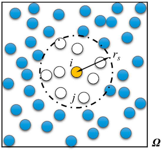
Figure 1.
Computational domain Ω, support domain of particle i (point circle line), radius of the support domain rs, and fluid particles (circles).
The values of an infinitely differentiable function F at the positions of particles i and j are defined as Fi and Fj, respectively. This F can be the pressure, velocity or density of particles in the computation. Let us expand this term as the Taylor series of F for particle i:
where Equation (5) is for two dimensions. x and y are the spatial coordinates of the particles, and hj = xj - xi, kj = yj − yi.
For the fourth-order FDPM, ignoring the high-order terms, the approximation of F is denoted by f:
After rearranging these equations and multiplying by a kernel function W on both sides of the equation, the sum of these expressions for all particles j is obtained:
where W(hj, kj, rs) is a kernel function in 2D and rs represents the size of the support domain. For W, different kernel functions, including Gaussian, cubic spline, and quintic spline functions, can be found in [13]. In the following equations, we use W for the kernel function.
Function G can be defined in 2D as
According to Equation (7), the norm of G equals 0, so we obtain:
where
Equation (9) gives us the following equation:
where
AD = B,
Since matrix A is symmetrical, Equation (11) can be solved, and the solution gives the values of the spatial derivatives in matrix D. Thus, the spatial derivatives in Equations (1) and (2) can be obtained by solving a set of symmetric linear equations, and the material derivatives in the equations can be integrated using a time integration scheme.
2.3. Particle Representation for Governing Equations
Taking particle i as an example, this section gives the particle representation of the governing equations and the solution to Equation (11). The solution includes the values of the spatial derivatives needed in the governing equations.
The coefficients of D and B are denoted by Dm(fi) and Bm(fi), respectively, with m = 1, 2, …, 5. For example, (the second coefficient in Equation(13)), and (the second coefficient in Equation (14)). In addition, the symmetric matrix A can be decomposed into the upper and lower triangular matrices A = LLT. The coefficients of the matrix L are denoted by L(m, n), with m and n = 1, 2, 3, 4, 5.
By using the GFD scheme and Cholesky factorization to solve Equation (11), we obtain the solutions for the Lagrangian derivative terms in Equations (1) and (2) in two-dimensional form
where ui and vi are the velocity of particle i in two directions and
where
This method considers changes in density and is able to simulate flow at low Mach numbers, so it is used to solve weakly compressible viscous flow problems. Calculations of particle motion and time integration are performed based on second-order leapfrog integration. The equations for updating the position and velocity of particles are
where is the velocity of fluid particle i at time , and Δt is the time step.
2.4. Artificial Particle Displacement
In simulations of flow in porous media (Section 3.5), artificial particle displacement is suggested as a particle motion correction to avoid particles in the vicinity of the stagnation points of fluid flow [38] and to avoid poor particle distributions [39]. Artificial particle displacement can be expressed as
where ri is the position of particle i, α is a problem-dependent parameter that is usually set between 0.01 and 0.1, vmax is the maximum velocity of all particles in the computational domain, rij = ri − rj which is the distance between particles i and j, and is the average distance between the neighboring particles of particle i:
It is noted that the problem-dependent parameter α should be selected carefully. This value should be small enough not to affect the physics of the flow but also large enough to avoid the accumulation of particles to form groups. In the present work, the value of artificial particle displacement is less than 0.1% of the physical particle displacement for a given time step, which is consistent with the magnitude in [40].
After moving the particles, the pressure and velocity components should be corrected by Taylor expansion.
2.5. Boundary Conditions
Several layers of virtual particles are used to implement the boundary condition. Similar treatments can be observed in the SPH and MPS simulations. On a flat wall, virtual particles are obtained by extending the boundary particles to the outside of the computational region, and the distribution of virtual particles is regular. The number of layers can be chosen according to the scale of the support domain. Figure 2 is a sketch of the treatment of particles near the wall. i represents the particle number, and Δx is the particle spacing.
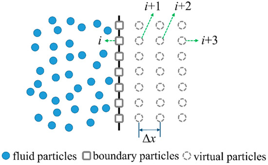
Figure 2.
A sketch of a simulation of an acoustic boundary using virtual particles. Fluid particles are inside the computational domain and boundary particles are fixed on the boundary.
For a flat wall, both the no-slip and free-slip boundary conditions can be implemented using virtual particles. For no-slip walls, the particle-based boundary conditions are as follows
For free-slip walls, the tangential velocity component of virtual particles is maintained the same as the boundary particles.
For a round surface, virtual particles are established based on a radial distribution inside the object domain with particle spacing Δx. The particle distribution is shown in Figure 3.
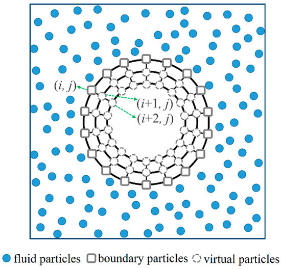
Figure 3.
A sketch of a simulation of an acoustic boundary with a curved surface using virtual particles. Fluid particles are inside the computational domain and boundary particles are fixed on the boundary.
The boundary condition for a rigid wall satisfies the following equations.
Since the FDPM simulation is still based on the local support domain, most boundary conditions in the existing Lagrangian particle-based methods, such as the SPH and MPS methods, can be used directly or implemented with minor changes. The particle representation of no-slip, free-slip and superhydrophobic surfaces [41,42,43] can be found in [44,45,46].
3. Applications of the Finite Difference Particle Method
3.1. Fundamental Definition
Several test cases are simulated with the FDPM based on second-order Taylor series expansion. The numerical accuracy is evaluated by the root mean square errors (εRMS) and the maximum errors (εMAX), which are defined as
where Snum(k) and Sana(k) are the numerical and analytical results of variable k, respectively. k could be the velocity or pressure.
The convergence rate of the FDPM is evaluated based on the root mean square error convergence rate (RERMS) and the maximum error convergence rate (REMAX) as follows:
3.2. Unsteady Flow in a Pipeline
Unsteady flow field in the pipeline is simulated to verify the FDPM method. The theoretical solutions of unsteady flow in a 1D pipeline (chapter 3 in book [47]) are
where u0 is the flow velocity distribution and x is the coordinate along the length of the pipeline. The coefficients (the unit can be obtained from dimensional analysis) C1 = 30.0, C2 = –1.0 × 10⁶, C3 = 82571.0, and γ = 1.4; moreover, the initial time is 12.5 s, and the pipe length x is 700 m.
The FDPM algorithm with a second-order Taylor truncation is used, and the time step (Δt) is 0.0029 s. The effect of viscosity in the process of fluid motion is not considered. Dirichlet boundary conditions are used at both ends of the boundary. The velocity, pressure and density of four particles at both ends are set based on theoretical values.
The space of the initial particle (Δx) is 5.0 m, and rs is 3.2 times Δx. The cubic spline kernel function is used in the calculations. Table 1 provides data for comparing the numerical velocity and theoretical solution of a particular particle at different times and positions. Notably, although the particle moves from x = 2.48 m to x = 25.64 m, the FDPM results agree well with the theoretical values, and this result verifies the algorithm.

Table 1.
FDPM results and theoretical solutions of the position and velocity of a particle (particle number: 70) at different times.
The convergence verification of the FDPM method for unsteady flow in a pipeline is shown in Figure 4. The numerical error curves at three different moments are given using different Δx values, and rs is 3.2 times Δx in the computation.
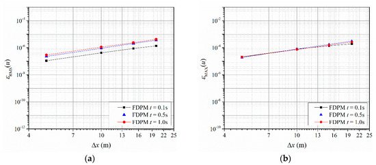
Figure 4.
Convergence curves of the FDPM method for 1D unsteady flow simulation: (a) Root mean square error, see Equation (26), of FDPM simulation using different particle spacing Δx at different time; (b) maximum error, see Equation (27), of FDPM simulation using different particle spacing Δx at different time.
Figure 4 shows that the FDPM method displays good convergence at different times. When t = 1.0 s, the convergence curve yields a RERMS value of 1.7 and REMAX value of 1.8.
Given that the FDPM is a KGF method, the effect of the type of kernel function on this method is evaluated. Four types of kernel functions, including , Gaussian, cubic spline and quintic spline functions, are compared through two types of errors with different rs conditions, as shown in Figure 5. The figure shows that the maximum error of the Gaussian kernel function is larger than that of the other methods. The errors of other types of functions are similar.
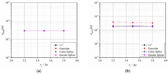
Figure 5.
Velocity errors of the computations with different kernel functions in pipe flow modeling: (a) Root mean square error, see Equation (26), of FDPM simulation using different smoothing length and kernel functions; (b) maximum error, see Equation (27), of FDPM simulation using different smoothing length and kernel functions.
3.3. Poisseuille Flow
Steady, axisymmetric Poisseuille flow between two infinite plates is a classical test model in hydrodynamics. In this section, the model is used to verify the governing equations and the rigid wall boundaries. Assuming that the distance between two infinite plates is L, the volume force F is loaded on the fluid between plates in the x direction from time t = 0. The theoretical solution of the velocity distribution of the flow at a given time [48] is as follows.
The numerical simulation for Poisseuille flow is obtained under weakly compressible (Ma = 0.0125) conditions. Based on reference [48], the parameters of the Poisseuille field are chosen as υk = 10−6 m2s−1, L = 10−3 m, ρ = 103 kgm−3, and F = 10−4 ms−2, so the maximum velocity is 1.25 × 10⁻⁵ ms−1 and the Reynold number is Re = 1.25 × 10⁻². The plate boundaries at the upper and lower ends are established using rigid walls. One layer of boundary particles and three layers of virtual particles are used. The FDPM with second-order Taylor truncation is utilized to perform the computation. The speed of sound c is taken as 0.001 m/s, as suggested in [49], and the time step Δt is 3.0 × 10⁻⁴ s. The initial particle spacings Δx and Δy are both set as 5 × 10⁻⁵ m, rs is 3.2 times Δx, and the kernel function is selected as a cubic spline function.
A comparison of the numerical and theoretical solutions of the velocity of the flow field in the x direction at different times is shown in Figure 6. The particle velocity is obtained by bilinear interpolation. As time increases, the positions of particles gradually change until the uniformly distributed particles at the initial stage are completely mixed in disorder. At this time, the numerical solution of the particle velocity is still consistent with the theoretical solution.
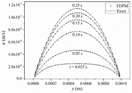
Figure 6.
Velocity profiles of the FDPM results (stars) and theoretical solutions (lines) at different times along the y direction (from the bottom plate to the top plate).
During the computation, the particle velocity remains symmetrically distributed and gradually increases at different times before reaching a steady state. The velocity of particles in the middle of the two plates is the largest due to the viscous force, and the velocity is small near the plates. The FDPM solution is in good agreement with the theoretical solution.
Figure 7 shows the numerical error curves of the FDPM method at different times and is used to analyze the convergence of the FDPM method. During the computation, rs remains 3.2 times Δx.
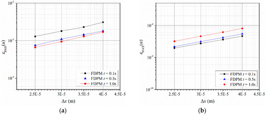
Figure 7.
Convergence curves of the FDPM computation in Poisseuille flow modeling: (a) Root mean square error, see Equation (26), of FDPM simulation using different particle spacing Δx at different time; (b) maximum error, see Equation (27), of FDPM simulation using different particle spacing Δx at different time.
Figure 7 shows that εRMS and εMAX decrease as Δx decreases, which indicates that the numerical accuracy converges with the initial particle spacing at different times. εRMS is on the order of 10−3, indicating that the computational results agree well with the theoretical solutions. For different error evaluation indexes, the RERMS and REMAX values of the FDPM method are approximately 1.7 and 1.8, respectively, with good convergence at t = 1.0 s. Since the second-order Taylor expansion-based FDPM is implemented in the test, the convergence rate is reasonable.
An error analysis of the four different types of kernel functions is conducted to analyze the sensitivity of the FDPM method to the kernel function, as shown in Figure 8.
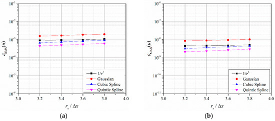
Figure 8.
Velocity errors of the computations with different kernel functions in Poisseuille flow modeling: (a) Root mean square error, see Equation (26), of FDPM simulation using different smoothing length and kernel functions; (b) maximum error, see Equation (27), of FDPM simulation using different smoothing length and kernel functions.
Figure 8 shows that different types of kernel functions can be used in the FDPM method and that the differences in the calculation errors are insignificant. The calculation errors of the four types of kernel functions from large to small exhibit the following order: Gaussian, r−3, cubic spline, and quantic spline.
3.4. Couette Flow
Couette flow considers the fluid flow between a stationary plate and a sliding plate. To accurately solve the flow distribution, the viscous term and boundary flow must be solved correctly. Initially, the two plates and the fluid between them remain stationary. At a constant speed, the upper plate begins to slide parallel to the lower plate. Assuming that the plate spacing is L and the sliding velocity is u0, the theoretical solution of the flow velocity over time in the direction perpendicular to the plate [48] is as follows:
Couette flow is numerically simulated under weakly compressible (Ma = 0.0125) conditions. The parameters for Couette flow are vk = 106 m2s−1, L = 10−3 m, ρ = 103 kgm−3, and u0 = 1.25 × 10⁻⁵ m/s.
The plate boundaries at the upper and lower ends are obtained using rigid walls, and the upper plate is set with a constant velocity u0. One layer of boundary particles and three layers of virtual particles are used. The FDPM with second-order Taylor truncation is utilized to perform the computation. The speed of sound c is taken as 0.001 m/s, and the time step Δt is 5.0 × 10⁻⁵ s. The initial particle spacings Δx and Δy are both set as 2.5 × 10⁻⁵ m, rs is 3.2 times Δx, and the kernel function selected is the cubic spline function. Figure 9 shows a comparison between the FDPM method and the theoretical solution for the flow velocity at different times.
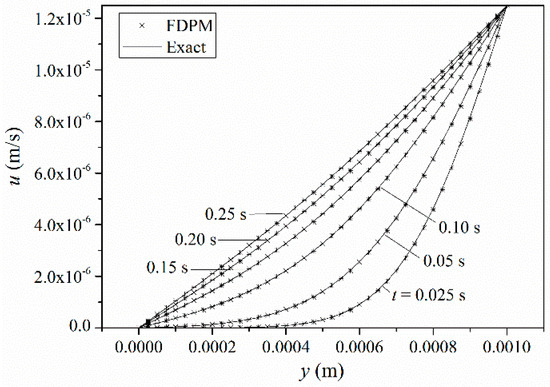
Figure 9.
Comparison of the FDPM result (stars) and the theoretical solution (lines) for the flow velocity at different times along the y direction (from the stationary plate to the sliding plate).
Before reaching a steady state, the particle velocity near the upper plate rapidly increases due to the viscous force, and that near the lower plate increases in a relatively slow manner. The velocity distribution of the particles between the two plates is nonlinear.
The velocity error (εRMS and εMAX) at different times and at different Δx values is used to evaluate the convergence of the FDPM, as shown in Figure 10.
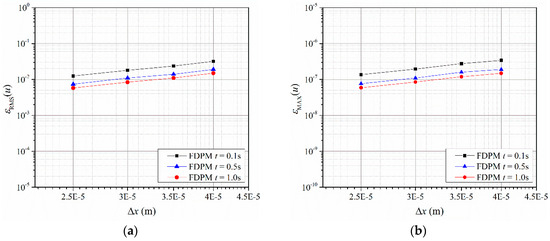
Figure 10.
Convergence curves of the FDPM computations in Couette flow modeling: (a) Root mean square error, see Equation (26), of FDPM simulation using different particle spacing Δx at different time; (b) maximum error, see Equation (27), of FDPM simulation using different particle spacing Δx at different time.
From the numerical results, both error indexes gradually decrease with decreasing Δx, which suggests that the numerical accuracy converges with the initial particle spacing at different times. εRMS is on the order of 10−2, indicating that the computational results agree well with the theoretical solution. When t = 1.0 s, the two errors result in an RERMS value of 1.7 and REMAX value of 1.8. Since the second-order Taylor expansion-based FDPM is implemented in the test, the convergence rate is reasonable.
To analyze the sensitivity of the FDPM method to the kernel function, four different types of kernel functions with different rs/Δx values are applied, as shown in Figure 11. Different types of kernel functions can be used in the FDPM method, and the calculation error of the Gaussian kernel function is larger than that of the other methods.
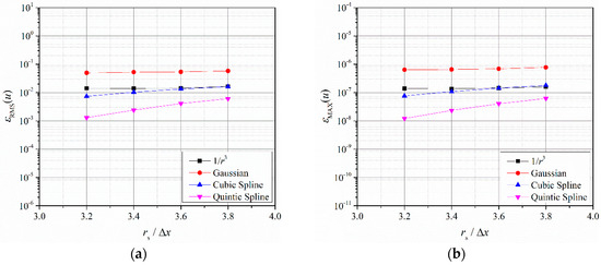
Figure 11.
Velocity errors of the computations with different kernel functions in Couette flow modeling: (a) Root mean square error, see Equation (26), of FDPM simulation using different smoothing length and kernel functions; (b) maximum error, see Equation (27), of FDPM simulation using different smoothing length and kernel functions.
3.5. Flow in Porous Media
In this section, the FDPM algorithm is used to simulate the flow in a simplified model of porous media [50]. The simplified model can be seen as flow around a circular cylinder, as shown in Figure 12, and four sides of the domain are periodic boundaries.
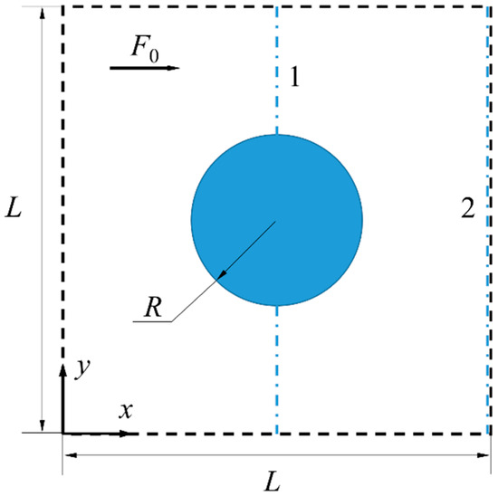
Figure 12.
Simplified model of porous media. The solid circle is a circular cylinder and four sides of the domain are periodic boundaries. L is the size of the computational domain, R is the cylindrical radius, and F0 is the volume force.
The size of the computational domain L = 0.1 m, the kinematic viscosity vk = 10−6 m2s−1, the cylindrical radius R = 2 × 10⁻² m, the volume force F0 = 1.5 × 10⁻⁷ ms−2, and the speed of sound c = 5.77 × 10⁻⁴ ms−1. Δx and Δy are 0.003 m, rs is 3.2 times Δx, Δt = 1.04 s with 2000 steps, and the coefficient of artificial particle displacement is 0.05. A rigid wall boundary is used for the cylindrical boundary, and a periodic boundary is used on the four sides of the computational domain. One layer of boundary particles and three layers of virtual particles are used. The FDPM with second-order Taylor truncation is utilized to perform the computations. The particle distribution and velocity contours at the initial time and the final steady state are shown in Figure 13.
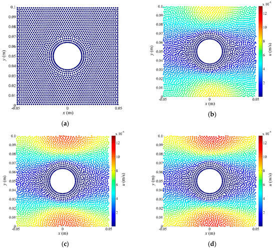
Figure 13.
Particle distribution (solid circles) and velocity contours from the initial time to the steady state: (a) t = 0, (b) t = 693 s, (c) t =1386 s and (d) t = 2080 s.
At the initial time, the particle distribution is regular. Then, the fluid begins to flow, and particles are gradually scattered and evenly distributed in the computational domain.
The velocity distributions along lines 1 and 2 (dotted-dashed lines in Figure 12) are shown in Figure 14. Both the FDPM results and finite element method (FEM) results are given to evaluate the accuracy of the numerical method. The FEM results come from the data of figure 6 in [48].
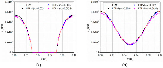
Figure 14.
Velocity distributions along observation lines 1 and 2 (dotted-dashed lines in Figure 12): (a) Observation line 1 and (b) observation line 2. Lines are FEM results and solid points are FDPM results with different particle spacing Δx.
When Δx > 0.004, the computation is not sufficiently stable and can easily collapse, so this condition is not shown in Figure 14. When Δx = 0.0038 m, the FDPM calculation results and the FEM results at x = 0 and 0.1 m produce significant differences. When Δx = 0.002 m, the FDPM results are similar to the FEM results. After convergence is obtained, the results of the FDPM method are consistent with the FEM results, which verifies the correctness of the numerical method and the boundary conditions.
A comparison of the FDPM results (Δx = 0.002 m) with different kernel functions and the FEM reference results is shown in Figure 15. The figure shows that the FDPM results with different types of kernel functions are comparable to the reference results and exhibit only minor differences.
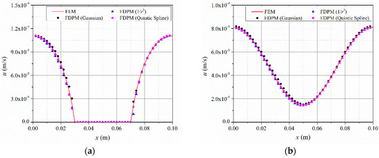
Figure 15.
Comparison along observation lines 1 and 2 (dotted-dashed lines in Figure 12) between the FDPM results (solid points) with different kernel functions and the FEM results (lines): (a) Observation line 1 and (b) observation line 2.
3.6. Lid-Driven Cavity Flow
The lid-driven cavity flow is widely used as a benchmark test case and the model in [51] is used to verify the method. The case is in a square cavity with a sliding plate on the upper side and three fixed rigid walls around, as shown in Figure 16. Initially, the fluid in the cavity remain stationary. At a constant speed, the upper plate begins to slide horizontally and the simulation is at Re = 100.
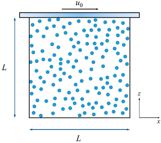
Figure 16.
Schematic of the lid-driven cavity flow. The solid circle is a circular cylinder and four sides of the domain are periodic boundaries. L is the size of the computational domain, R is the cylindrical radius, and F0 is the volume force.
Rigid wall boundary condition is used for four sides of the cavity, and the upper plate is set with a constant velocity u0. The size of the cavity L = 1.0 m, the kinematic viscosity vk = 0.01 m2s−1, the sliding velocity u0 = 1.0 m/s, and the speed of sound c = 10.0 ms−1. Δx and Δy are 0.025 m, rs is 2.7 times Δx, Δt = 0.001 s with 3000 steps, the coefficient of artificial particle displacement is 0.05, and the kernel function selected is the cubic spline function. One layer of boundary particles and three layers of virtual particles are used. The FDPM with second-order Taylor truncation is utilized to perform the computations. The particle distribution and velocity contours at the initial time and the final steady state are shown in Figure 17.
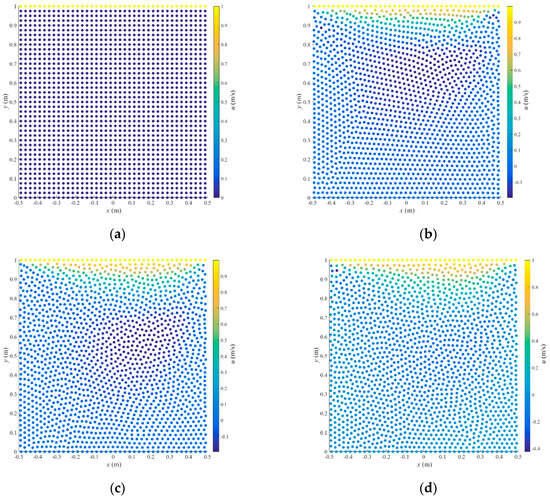
Figure 17.
Particle distribution (solid circles) and velocity contours from the initial time to the steady state: (a) t = 0, (b) t = 1.0 s, (c) t =2.0 s and (d) t = 3.0 s.
At the initial time, the particle distribution is regular. Then, the fluid begins to flow, and particles are gradually scattered and evenly distributed in the computational domain.
Horizontal velocity component profiles along horizontal and vertical geometric centerlines at t = 3.0 s, respectively, are shown in Figure 18. Although the present FDPM computation employed only 2/5 particles in the work [51], these profiles are in good agreement with the reference results. The particle distribution shows the method works well in geometries with corners.
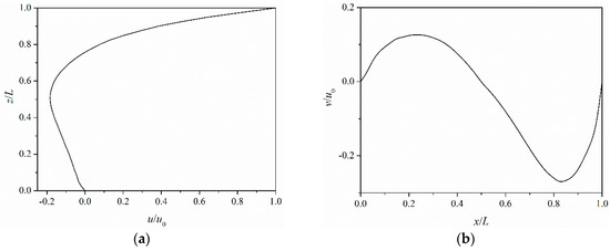
Figure 18.
Horizontal Velocity distributions along horizontal and vertical geometric centerlines at t = 3.0 s: (a) Along vertical geometric centerlines and (b) along horizontal geometric centerlines.
4. Conclusions
In this paper, a particle method based on the GFD scheme is proposed to simulate weakly compressible viscous flow. This approach represents the partial differential terms in the Navier-Stokes equations as the solution of a symmetric system of linear equations. The convergence and accuracy of the symmetric particle-based method are tested by modeling flow in a pipeline, Poisseuille flow, Couette flow, flow in porous media, and lid-driven cavity flow. The numerical results exhibit close agreement with the theoretical solutions and finite element results. The particle method utilizes the kernel function itself instead of its gradient, which avoids using artificial parameters to solve for the viscous term and reduces the limitations on the choice of kernel function. Moreover, the order of the Taylor series expansion can easily be improved in the meshless algorithm. The convergence rate of the particle-based calculations with second-order Taylor truncation is approximately 1.7 in the tests, and four different kernel functions are tested and determined to be reliable.
Author Contributions
These authors contributed equally to this work.
Funding
This research was funded by National Natural Science Foundation of China (grant number 51809208 and 51741910) and Fundamental Research Funds for the Central Universities (grant number WUT: 2018IVA032).
Conflicts of Interest
The authors declare no conflict of interest.
References
- Kim, K.S. A Mesh-Free Particle Method for Simulation of Mobile-Bed Behavior Induced by Dam Break. Appl. Sci. 2018, 8, 1070. [Google Scholar] [CrossRef]
- De Padova, D.; Mossa, M.; Sibilla, S. SPH numerical investigation of characteristics of hydraulic jumps. Environ. Fluid Mech. 2018, 18, 849–870. [Google Scholar] [CrossRef]
- Zuo, J.; Tian, W.; Chen, R.; Qiu, S.; Su, G. Two-dimensional numerical simulation of single bubble rising behavior in liquid metal using moving particle semi-implicit method. Prog. Nucl. Energy 2013, 64, 31–40. [Google Scholar] [CrossRef]
- Zhang, A.; Sun, P.; Ming, F. An SPH modeling of bubble rising and coalescing in three dimensions. Comput. Methods Appl. Mech. Eng. 2015, 294, 189–209. [Google Scholar] [CrossRef]
- Wang, X.; Ban, X.; He, R.; Wu, D.; Liu, X.; Xu, Y. Fluid-Solid Boundary Handling Using Pairwise Interaction Model for Non-Newtonian Fluid. Symmetry 2018, 10, 94. [Google Scholar] [CrossRef]
- Liu, S.; Ban, X.; Wang, B.; Wang, X. A Symmetric Particle-Based Simulation Scheme towards Large Scale Diffuse Fluids. Symmetry 2018, 10, 86. [Google Scholar] [CrossRef]
- Lucy, L.B. A numerical approach to the testing of the fission hypothesis. Astron. J. 1977, 82, 1013–1024. [Google Scholar] [CrossRef]
- Gingold, R.A.; Monaghan, J.J. Smoothed particle hydrodynamics: Theory and application to non-spherical stars. Mon. Not. R. Astron. Soc. 1977, 181, 375–389. [Google Scholar] [CrossRef]
- Monaghan, J. Smoothed Particle Hydrodynamics and Its Diverse Applications. Annu. Rev. Fluid Mech. 2012, 44, 323–346. [Google Scholar] [CrossRef]
- Violeau, D.; Rogers, B.D. Smoothed particle hydrodynamics (SPH) for free-surface flows: Past, present and future. J. Hydraul. Res. 2016, 54, 1–26. [Google Scholar] [CrossRef]
- Wang, Z.-B.; Chen, R.; Wang, H.; Liao, Q.; Zhu, X.; Li, S.-Z. An overview of smoothed particle hydrodynamics for simulating multiphase flow. Appl. Math. Model. 2016, 40, 9625–9655. [Google Scholar] [CrossRef]
- Zhang, A.-M.; Sun, P.-N.; Ming, F.-R.; Colagrossi, A. Smoothed particle hydrodynamics and its applications in fluid-structure interactions. J. Hydrodyn. 2017, 29, 187–216. [Google Scholar] [CrossRef]
- Liu, G.R.; Liu, M.B. Smoothed Particle Hydrodynamics—A Meshfree Particle Method; World Scientific Publishing: Singapore, 2003; pp. 103–176. [Google Scholar]
- Liu, M.B.; Liu, G.R. Smoothed Particle Hydrodynamics (SPH): An Overview and Recent Developments. Arch. Comput. Methods Eng. 2010, 17, 25–76. [Google Scholar] [CrossRef]
- Cleary, P.W.; Prakash, M.; Ha, J.; Stokes, N.; Scott, C. Smooth particle hydrodynamics: Status and future potential. Prog. Comput. Fluid Dyn. Int. J. 2007, 7, 70–90. [Google Scholar] [CrossRef]
- Cummins, S.J.; Rudman, M. An SPH projection method. J. Comput. Phys. 1999, 152, 584–607. [Google Scholar] [CrossRef]
- Chen, J.K.; Beraun, J.E.; Jih, C.J. An improvement for tensile instability in smoothed particle hydrodynamics. Comput. Mech. 1999, 23, 279–287. [Google Scholar] [CrossRef]
- Chen, J.K.; Beraun, J.E.; Carney, T.C. A corrective smoothed particle method for boundary value problems in heat conduction. Int. J. Numer. Methods Eng. 1999, 46, 231–252. [Google Scholar] [CrossRef]
- Zhang, G.M.; Batra, R.C. Modified smoothed particle hydrodynamics method and its application to transient problems. Comput. Mech. 2004, 34, 137–146. [Google Scholar] [CrossRef]
- Liu, M.; Liu, G.; Lam, K. Constructing smoothing functions in smoothed particle hydrodynamics with applications. J. Comput. Appl. Math. 2003, 155, 263–284. [Google Scholar] [CrossRef]
- Huang, C.; Lei, J.M.; Liu, M.B.; Peng, X.Y. A kernel gradient free (KGF) SPH method. Int. J. Numer. Methods Fluids 2015, 78, 691–707. [Google Scholar] [CrossRef]
- Lei, J.M.; Peng, X.Y. Improved kernel gradient free-smoothed particle hydrodynamics and its applications to heat transfer problems. Chin. Phys. B 2015, 25, 020202. [Google Scholar] [CrossRef]
- Huang, C.; Lei, J.M.; Liu, M.B.; Peng, X.Y. An improved KGF-SPH with a novel discrete scheme of Laplacian operator for viscous incompressible fluid flows. Int. J. Numer. Methods Fluids 2016, 81, 377–396. [Google Scholar] [CrossRef]
- Koh, C.G.; Gao, M.; Luo, C. A new particle method for simulation of incompressible free surface flow problems. Int. J. Numer. Meth. Eng. 2012, 89, 1582–1604. [Google Scholar] [CrossRef]
- Luo, M.; Koh, C.G.; Bai, W.; Gao, M. A particle method for two-phase flows with compressible air pocket. Int. J. Numer. Methods Eng. 2016, 108, 695–721. [Google Scholar] [CrossRef]
- Jensen, P.S. Finite difference techniques for variable grids. Comput. Struct. 1972, 2, 17–29. [Google Scholar] [CrossRef]
- Perrone, N.; Kao, R. A general finite difference method for arbitrary meshes. Comput. Struct. 1975, 5, 45–57. [Google Scholar] [CrossRef]
- Liszka, T.; Orkisz, J. The finite difference method at arbitrary irregular grids and its application in applied mechanics. Comput. Struct. 1980, 11, 83–95. [Google Scholar] [CrossRef]
- Ding, H.; Shu, C.; Yeo, K.; Xu, D. Simulation of incompressible viscous flows past a circular cylinder by hybrid FD scheme and meshless least square-based finite difference method. Comput. Methods Appl. Mech. Eng. 2004, 193, 727–744. [Google Scholar] [CrossRef]
- Li, P.-W.; Chen, W.; Fu, Z.-J.; Fan, C.-M. Generalized finite difference method for solving the double-diffusive natural convection in fluid-saturated porous media. Eng. Anal. Bound. Elem. 2018, 95, 175–186. [Google Scholar] [CrossRef]
- Gavete, L.; Ureña, F.; Benito, J.; García, A.; Ureña, M.; Salete, E.; Corvinos, L.A.G. Solving second order non-linear elliptic partial differential equations using generalized finite difference method. J. Comput. Appl. Math. 2017, 318, 378–387. [Google Scholar] [CrossRef]
- Benito, J.; Ureña, F.; Gavete, L. Influence of several factors in the generalized finite difference method. Appl. Math. Model. 2001, 25, 1039–1053. [Google Scholar] [CrossRef]
- Gavete, L.; Gavete, M.; Benito, J. Improvements of generalized finite difference method and comparison with other meshless method. Appl. Math. Model. 2003, 27, 831–847. [Google Scholar] [CrossRef]
- Benito, J.; Ureña, F.; Gavete, L. Solving parabolic and hyperbolic equations by the generalized finite difference method. J. Comput. Appl. Math. 2007, 209, 208–233. [Google Scholar] [CrossRef]
- Alamri, S.Z.; Ellahi, R.; Shehzad, N.; Zeeshan, A. Convective radiative plane Poiseuille flow of nanofluid through porous medium with slip: An application of Stefan blowing. J. Mol. Liq. 2019, 273, 292–304. [Google Scholar] [CrossRef]
- Ellahi, R.; Shivanian, E.; Abbasbandy, S.; Hayat, T. Numerical study of magnetohydrodynamics generalized Couette flow of Eyring-Powell fluid with heat transfer and slip condition. Int. J. Numer. Methods Heat Fluid Flow 2016, 26, 1433–1445. [Google Scholar] [CrossRef]
- Shehzad, N.; Zeeshan, A.; Ellahi, R.; Rashidi, S. Modelling Study on Internal Energy Loss Due to Entropy Generation for Non-Darcy Poiseuille Flow of Silver-Water Nanofluid: An Application of Purification. Entropy 2018, 20, 851. [Google Scholar] [CrossRef]
- Bašić, J.; Degiuli, N.; Werner, A. Simulation of water entry and exit of a circular cylinder using the ISPH method. Trans. Famena 2014, 38, 45–62. [Google Scholar]
- Nestor, R.M.; Basa, M.; Lastiwka, M.; Quinlan, N.J. Extension of the finite volume particle method to viscous flow. J. Comput. Phys. 2009, 228, 1733–1749. [Google Scholar] [CrossRef]
- Ozbulut, M.; Yildiz, M.; Goren, O. A numerical investigation into the correction algorithms for SPH method in modeling violent free surface flows. Int. J. Mech. Sci. 2014, 79, 56–65. [Google Scholar] [CrossRef]
- Rothstein, J.P. Slip on superhydrophobic surfaces. Annu. Rev. Fluid Mech. 2010, 42, 89–109. [Google Scholar] [CrossRef]
- Gentili, D.; Bolognesi, G.; Giacomello, A.; Chinappi, M.; Casciola, C.M. Pressure effects on water slippage over silane-coated rough surfaces: Pillars and holes. Microfluid. Nanofluidics 2014, 16, 1009–1018. [Google Scholar] [CrossRef]
- Bolognesi, G.; Cottin-Bizonne, C.; Pirat, C. Evidence of slippage breakdown for a superhydrophobic microchannel. Phys. Fluids 2014, 26, 082004. [Google Scholar] [CrossRef]
- Marrone, S.; Antuono, M.; Colagrossi, A.; Colicchio, G.; Le Touzé, D.; Graziani, G. δ-SPH model for simulating violent impact flows. Comput. Methods Appl. Mech. Eng. 2011, 200, 1526–1542. [Google Scholar] [CrossRef]
- Adami, S.; Hu, X.; Adams, N.; Adams, N. A generalized wall boundary condition for smoothed particle hydrodynamics. J. Comput. Phys. 2012, 231, 7057–7075. [Google Scholar] [CrossRef]
- Sun, P.; Ming, F.; Zhang, A. Numerical simulation of interactions between free surface and rigid body using a robust SPH method. Ocean Eng. 2015, 98, 32–49. [Google Scholar] [CrossRef]
- Von Mises, R.; Geiringer, H.; Ludford, G.S.S. Mathematical Theory of Compressible Fluid Flow; Chapter 3; Academic Press: New York, NY, USA, 2004. [Google Scholar]
- Morris, J.P.; Fox, P.J.; Zhu, Y. Modeling Low Reynolds Number Incompressible Flows Using SPH. J. Comput. Phys. 1997, 136, 214–226. [Google Scholar] [CrossRef]
- Liu, M.; Xie, W.; Liu, G. Modeling incompressible flows using a finite particle method. Appl. Math. Model. 2005, 29, 1252–1270. [Google Scholar] [CrossRef]
- Fang, J.; Parriaux, A. A regularized Lagrangian finite point method for the simulation of incompressible viscous flows. J. Comput. Phys. 2008, 227, 8894–8908. [Google Scholar] [CrossRef]
- Khorasanizade, S.; Sousa, J.M.M.; De Sousa, J.M. A detailed study of lid-driven cavity flow at moderate Reynolds numbers using Incompressible SPH. Int. J. Numer. Methods Fluids 2014, 76, 653–668. [Google Scholar] [CrossRef]
© 2019 by the authors. Licensee MDPI, Basel, Switzerland. This article is an open access article distributed under the terms and conditions of the Creative Commons Attribution (CC BY) license (http://creativecommons.org/licenses/by/4.0/).