Article

Symmetrical Patterns of Ainu Heritage and Their Virtual and Physical Prototyping

1
Graduate School of Engineering, Kitami Institute of Technology, 165 Koen-cho, Kitami 090-8507, Japan
2
Faculty of Engineering, Kitami Institute of Technology, 165 Koen-cho, Kitami 090-8507, Japan
*
Author to whom correspondence should be addressed.
Symmetry 2019, 11(8), 985; https://doi.org/10.3390/sym11080985
Submission received: 19 June 2019 / Revised: 29 June 2019 / Accepted: 18 July 2019 / Published: 2 August 2019
(This article belongs to the Special Issue Empirical Aesthetics)

Abstract

:
This article addresses virtual and physical prototyping of some symmetrical patterns collected from the Ainu cultural heritage. The indigenous people living in the northern part of Japan (e.g., Hokkaido), known as Ainu, often decorate their houses, clothing, ornaments, utensils, and spiritual goods using some unique patterns. The patterns carry their identity as well as their sense of aesthetics. Nowadays, different kinds of souvenirs and cultural artifacts crafted with Ainu patterns are cherished by many individuals in Japan and abroad. Thus, the Ainu patterns carry both cultural and commercial significance. A great deal of craftsmanship is needed to produce the Ainu patterns precisely. There is a lack of human resources having such craftsmanship. It will remain the same in the foreseeable future. Thus, there is a pressing need to preserve such craftsmanship. Digital manufacturing technology can be used to preserve the Ainu pattern-making craftsmanship. From this perspective, this article presents a methodology to create both virtual and physical prototypes of Ainu patterns using digital manufacturing technology. In particular, a point cloud-based approach was adopted to model the patterns. A point cloud representing a pattern was then used to create a virtual prototype of the pattern in the form of a solid CAD model. The triangulation data of each solid CAD model were then used to run a 3D printer to produce a physical prototype (replica of the pattern). The virtual and physical prototypes of both basic (Hokkaido) Ainu motifs and some synthesized patterns were reproduced using the presented methodology. The findings of this study will help those who want to digitize the craftsmanship of culturally significant artifacts without using a 3D scanner or image processing.

1. Introduction

Nowadays, virtual modeling and reverse engineering are extensively used in preserving and studying cultural-heritage-relevant artifacts [1]. In particular, such issues as shape perception enhancement, restoration and preservation, monitoring, and object interpretation and collection analysis require the support of solid CAD modeling and reverse engineering at micro, meso, and macro levels [1]. Although the size of the digitally searchable collection of virtual cultural artifices is growing very fast, there has been less progress in shape perception and analysis [1]. In order to enhance shape perception and analysis, the concept of symmetry can play an important role, because of the following reason: Hann [2] reported a large number of patterns collected from numerous sources (ancient civilizations of stupas and mandalas, Islamic Spain, Safavid Persia, Ottoman Turkey, Indian subcontinent, Indonesia, dynastic China, Korea, and Japan). The reported patterns exhibit symmetry that can be analyzed using some simple geometric entities, namely, segments of intersecting circles (“vesical piscis”), construction based on equilateral triangles and vesical piscis, construction based on hexagons, construction based on “four circles over one,” equilateral triangles, isosceles triangles, equilateral triangles, right angle triangles, regular hexagons, regular pentagons, “5-4-3 triangles,” construction based on 36 degree isosceles triangles, equilateral triangle grids, regular hexagon grids, squire grids, square and root triangles, construction based on the golden section triangle and diagonal of a rectangle, whirling square rectangles, squares with Brune’s star-type divisions, and Brune’s stars with intersections [2] (pp. 16–24,34). In addition, such simple operations as translation, two-fold rotation, reflection, and glide-reflection applied to the abovementioned geometric entities can create patterns that are often seen in the cultural artifacts of the abovementioned civilizations [2]. Moreover, analyzing symmetry can facilitate the geometric modeling performed on the digital data of the artifacts with cultural significance [3,4].
The cultural heritage of indigenous people (e.g., Nahuas living in Mexico and El Salvador, Ainu living in the northern hemisphere of the world, Assyrians living in Western Asia, and the like) is full of aesthetic patterns, which can also be studied using the concept of symmetry. The focus of this article is the patterns of the indigenous people living in the northern part of Japan, known as Ainu [5,6]. Ainu people decorate their houses, clothing, ornaments, utensils, and spiritual goods using some unique patterns [7,8,9,10,11,12]. The patterns exhibit symmetry, carry their identity, and a sense of aesthetics. Nowadays, different kinds of souvenirs and cultural artifacts are crafted with Ainu patterns, which are cherished by many individuals in Japan and abroad [13]. Thus, the Ainu patterns carry both cultural and commercial significance. Many shops all over Hokkaido sell souvenirs and artifacts crafted with Ainu patterns. There are even shopping streets (e.g., the shopping street at Akan Sap [14]) that are specialized in products crafted with Ainu patterns. Figure 1 shows some pictures of such products taken recently at the shopping street located in Akan Spa. A great deal of craftsmanship is needed to produce the Ainu patterns precisely. The remarkable point is that there is a lack of human resources who can produce the patterns. This trend will remain the same in the foreseeable future, creating a pressing need to preserve the Ainu pattern-making craftsmanship. To preserve the craftsmanship, one of the pragmatic options is to use digital manufacturing technology. From this perspective, this article presents a methodology to create both virtual and physical prototypes of some Ainu patterns, and also demonstrates its efficacy through some case studies. Particularly, a point cloud-based approach was adopted to model the patterns. The point cloud representing a pattern was then used to create a virtual model of the pattern in the form of a solid CAD model. Finally, the triangulation data of each solid CAD model were used to run a 3D printer for producing a physical prototype (replica of the pattern). The virtual and physical prototypes of both basic (Hokkaido) Ainu patterns and some complex patterns were produced by applying the proposed methodology.
Therefore, the rest of this article is organized as follows. Section 2 presents the basic motifs that are used to create all kinds of patterns found in the artifacts used by the Ainu community living in Hokkaido. Section 3 describes a methodology to model a pattern, and, thereby, to produce its virtual and physical prototypes. Section 4 presents some results obtained by applying the methodology. Section 5 concludes this article.

2. Basic Motifs

Before presenting the methodology intended to mimic the Ainu pattern-making craftsmanship using digital manufacturing technology, it is important to know about the origins of the patterns as reported in the literature. As in other cases, Ainu patterns can also be classified into two broad categories, namely, primary patterns and synthesized patterns. The primary patterns are hereinafter referred to as basic motifs. As a result, any combinations of the basic motifs yields a synthesized pattern. This section describes only the basic motifs of the Ainu community living in Hokkaido. The Ainu communities living in other regions have their own basic motifs, because the motifs carry the identity and a sense of aesthetics of the respective community.
Numerous authors have reported the basic motifs (e.g., see the work [7,8,9,11]) used by the Ainu community living in Hokkaido [10,12]. The Sapporo city authority has summarized the basic motifs into fourteen types, which are listed in Table 1.
As seen in Table 1, the first twelve motifs have names, whereas the other two do not have any name. In particular, Motif No. 1 (called Ayus in the Ainu language) takes the shape of a thorn. Motif No. 2 (Morew in the Ainu language) takes the shape of a spiral. Motif No. 3 (called Arus-Morew in Ainu language) takes the shape of a spiral with small thorns. Motif No. 4 (called Sikike-nu-Morew in the Ainu language) takes the shape of a spiral with corners. Motif No. 5 (called Sik in the Ainu language) takes the shape of an eye. Motif No. 6 (called Utasa in the Ainu language) takes the shape of an intersection. Motif No. 7 (Uren-Morew in the Ainu language) takes the shape of two spirals. Motif No. 8 (Ski-uren-Morew in the Ainu language) takes the shape of two spirals with an eye. Motif No. 9 (called Morew-etok in the Ainu language) takes the shape of a spiral plant. Motif No. 10 (called Punkar in the Ainu language) takes the shape of a vane. Motif No. 11 (called Apapo-piras (u) ke in the Ainu language) takes the shape of a flower. Motif No. 12 (called Apapo-epuy in the Ainu language) takes the shape of a flower bud. Motifs No. 13 and 14 do not have Ainu names, but they look like a heart type shape and a fishing bell shape, respectively. Although some authors have studied the significances of these motifs [7,8,9,11], a more comprehensive study lies ahead. As far as modeling is concerned, the motifs called Morew, Sik, Utasa, and Ayus have been frequently used, and thus can be defined as the main motifs. Arus-Morew, Sikike-nu-Morew, Sikike-nu-Morew, and Uren-Morew are the motifs created by modifying the main motifs, and thus can be defined as the first-order synthetic motifs. The motifs called Morew-etok, Punkar, Apapo-piras (u) ke, and Apapo-epuy represent plants, and thus can be defined as the plant motifs. The other motifs (i.e., Motifs No. 13 and No. 14) can be defined as the other motifs.

3. Pattern Digitization Methodology

This section describes a general methodology that can be used to digitize a 2D pattern for the sake of virtual and physical prototyping. Before proposing the methodology, some of the salient points must be described first, as follows.
The digital technology called reverse engineering [16] has been extensively used in cultural artifact preservation and prototyping [17,18,19,20,21,22,23,24,25] because it (reverse engineering) helps create digital or geometric models of existing physical objects when these models (digital or geometric models) are unavailable. In most cases, reverse engineering uses scanning (e.g., [19,20] or image processing [18] techniques to extract the shape, topological, and texture information of an existing physical object. The extracted information must be processed to create the (digital) virtual model of the object using CAD systems. Once the digital data of the virtual models are available, physical models (often referred to as prototypes or replicas) can be produced using a manufacturing process (additive manufacturing (e.g., 3D printing) [21], subtractive manufacturing (CNC machining), or formative manufacturing (casting)). However, depending on the level of automation and accuracy, the object information obtained by the scanning or image processing techniques must undergo a set of sophisticated and complicated transformations. The transformations include surface reconstruction from the point clouds obtained by 3D scanning or imaging (photogrammetric technique), reduction of redundant information (e.g., reduction of redundant points from a point cloud), and hierarchical decomposition of a point cloud or image data based on depth, color, and density, and other factors. Among others, Geng and Bidanda [16] and Tashi et al. [25] provided a relatively comprehensive account of the computational complexity associated with the transformations mentioned above. However, studying the abovementioned transformations is an active field of research [26], as there are many unsolved issues.
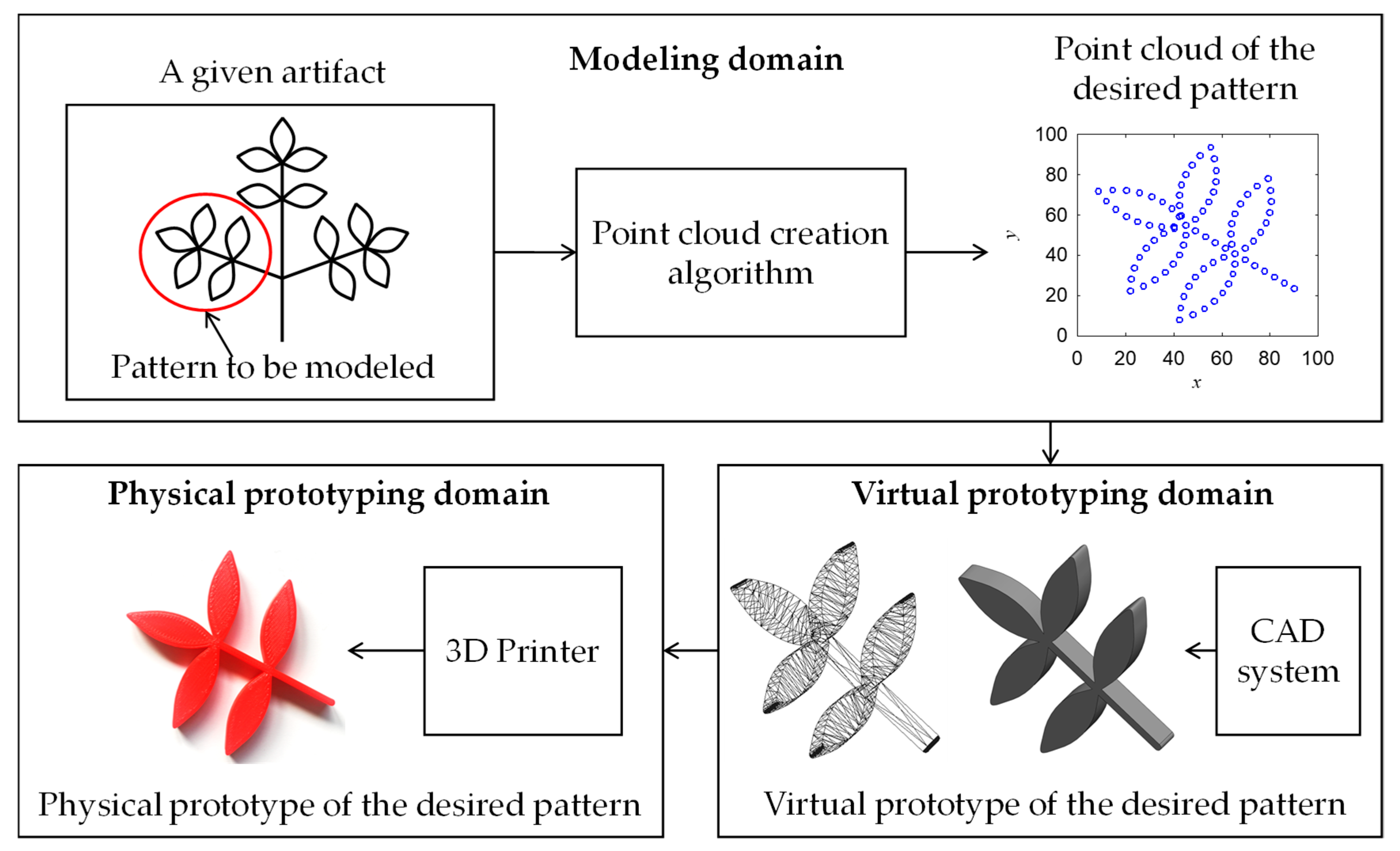
In order to avoid the abovementioned computational complexity, other alternative approaches can be considered. In this respect, the following three studies can be noted. The first alternative approach described here is taken from the work of Tamaki et al. [27], where it was shown that a special type of photo-curing resin can be used to extract the shape information of an object (in their case, a snow crystal) for the sake of physical prototyping. This technique works well when the object is tiny. The parameters that affect the curing process of the resin play an important role in the shape information extraction process. Another alternative approach was developed by Rojas-Sola et al. [28], where the virtual model of a historical artifact (in this case, an engine) was constructed using a commercially available CAD system. The 2D sketch of the artifact was used as the reference model while building the virtual model. This technique relies on the perception of the model builder, and worked well when the object consisted of some simple geometrical shapes (e.g., plate, line, circle, cylinder, and similar). The authors did not report any results regarding the physical prototyping of the artifact (the engine). The other alternative was developed by Tashi et al. [25], who used analytical point clouds to represent the relevant segment of a given artifact for virtual and physical prototyping. In this approach, both a set of equations and an algorithm were needed to create the desired point cloud. The point cloud was used to create a solid CAD model (virtual prototype) of the object using commercially available CAD systems. The solid CAD model was used to create a physical prototype using a commercially available 3D printer. In this article, this approach was adopted. For the sake of systemization of the whole modeling process, three domains were considered, namely, the modeling domain, virtual prototyping domain, and physical prototyping domain. Figure 2 schematically illustrates these three domains. As seen in Figure 2, in the modeling domain, a model builder first studies the object and determines the pattern to be modeled. Subsequently, the model builder fixes the values of the parameters of the point cloud creation algorithm (shown below), namely, center point (Pc), initial length (d), initial angle (ϕ), instantaneous distance (ri|i = 0,1,…,n), and instantaneous rotational angle (θi|i = 0,1,…,n). If the model builder is satisfied, then the output of the algorithm is collected as the point cloud (PC) that is the model of the desired pattern. In the virtual prototyping domain, the model builder inputs the point cloud (PC) to an appropriate CAD system and performs solid modeling using the functions offered by the system. This results in a virtual prototype (solid CAD model). Finally, the physical prototyping domain acknowledges the triangulation data (often referred to as STL data) of the solid CAD model and uses a commercially available 3D printer to produce the physical prototype of the pattern. Other manufacturing means can be used if preferred.
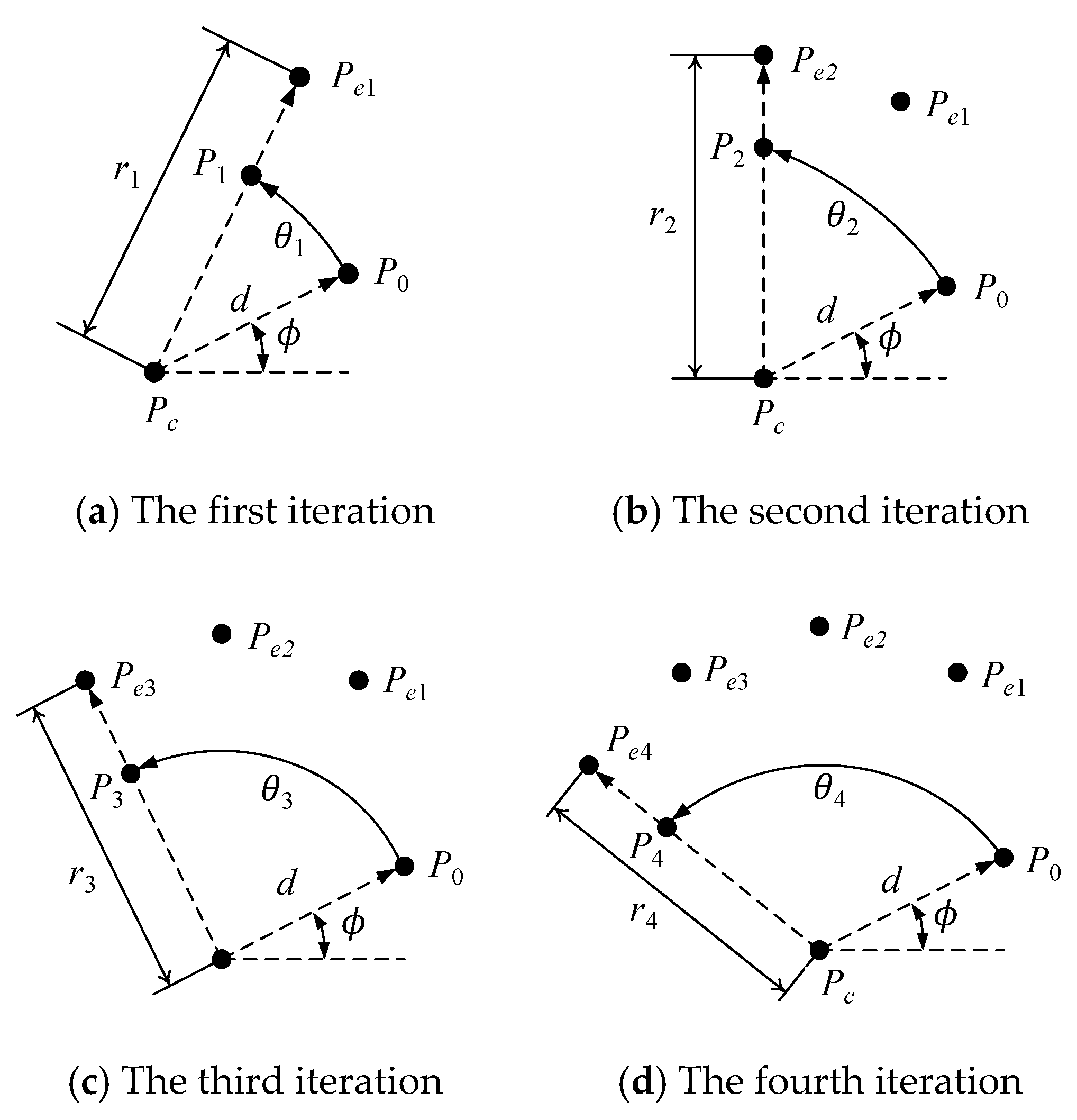
The mathematical settings of the point cloud creation algorithm (Algorithm 1) that were used to model the Ainu patterns shown in this article were adopted from Tashi et al. [25]. The algorithm consists of four steps, as shown below. The first step is the input step, the second step is the calculation step, the third step is the iteration step, and the last step is the output step. In the input step, the center point Pc = (Pcx,Pcy) ∈ ℜ2, initial distance d > 0, initial angle ϕ ∈ ℜ, instantaneous distances (ri ∈ ℜ|i = 0,1,…,n), and instantaneous rotational angles (θi ∈ ℜ|i = 0,1,…, n) are defined. In the calculation step, the initial point P0 = (P0x,P0y) is calculated, which is a point at a distance d from Pc on the line PcP0, making an angle ϕ with the x-axis in the counter-clockwise direction. In the iteration step, P0 is first rotated in the counter-clockwise direction of the x-axis using θi to create the points Pi = (Pix,Piy), i = 0,1,…,n. Afterward, the points denoted as Pi = (Pix,Piy), i = 0,1,…,n, are placed at the distances given by ri from Pc, resulting in the points Pei = (Pix,Piy), i = 0,1,…,n. In the output step, the points Pei = (Pix,Piy), i = 0,1,…,n, are collected as the point cloud denoted as PC = (Pei|i = 0,1,…,n).
The working principle of the algorithm is schematically illustrated in Figure 3, using the first four iterations for some arbitrary values of the instantaneous distance and rational angle. The algorithm can be used for creating different kinds of planar shapes not limited to the patterns shown in this article. Since most of the cultural-heritage-relevant shapes reported here and elsewhere [2] are symmetrical, the point cloud (PC) that models a segment of a given symmetrical shape can be rotated and translated several times to create a set of symmetrical PCs that model the other segments of the shape. In this case, the parameters called initial angle and distance become instrumental. The reason is as follows: If PC1 and PC2 are created by setting ϕ = a, ϕ = b, respectively, then both PC1 and PC2 are symmetrical point clouds but separated by an angular difference of ba. Similarly, if PC1 and PC2 are created by setting d = a, d = b, respectively, then both PC1 and PC2 are symmetrical point clouds but placed at a distance (ba)cosϕ in the x-direction and (ba)sinϕ in the y-direction. As a result, from the viewpoint of symmetrical patterns, both initial angle and distance bear a great deal of significance.
Algorithm 1 Point Cloud Creation Algorithm
1 Define:Center Point Pc = (Pcx,Pcy) ∈ ℜ2, Initial Length d > 0, Initial Angle ϕ ∈ ℜ
Instantaneous Distance (ri ∈ ℜ|i = 0,1,…,n)
Instantaneous Rotational Angle (θi ∈ ℜ|i = 0,1,…,n)
2 Calculate:P0 = (P0x, P0y) so that P 0 x = P c x + d cos ϕ and P 0 y = P c y + d sin ϕ
3 Iterate:For i = 0,1,…,n
     Rotate P0 by an angle θi around Pc in the counter-clockwise direction to
     create Pi = (Pix,Piy) so that
P i x = P c x + ( P 0 x P c x ) cos θ i ( P 0 y P c y ) sin θ i
P i y = P c y + ( P 0 x P c x ) sin θ i + ( P 0 y P c y ) cos θ i
     Extend Pi to Pei (a point on the line PcPi at a distance ri from Pc)
P e i x = P c x + ( P i x P c x ) ( r i / d )
P e i y = P c y + ( P i y P c y ) ( r i / d )
End For
4 Output:PC = (Pei|i = 0,1,…,n)
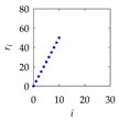
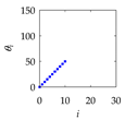
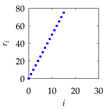
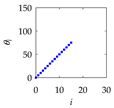
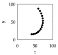
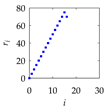
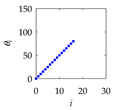
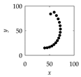
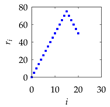
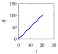
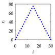
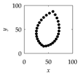
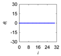
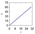
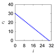
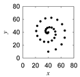
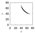
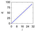
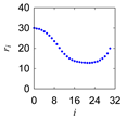
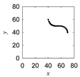
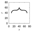
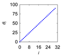
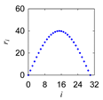
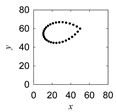
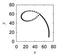
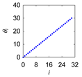
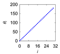
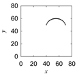
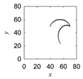
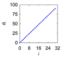
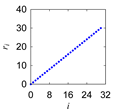
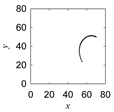
When a representative segment of a symmetrical pattern is modeled by PC, the user must be aware of how to fix the values of instantaneous distance and rotational angle. In most cases, a simple monotonic function (a straight line with positive or negative slope) or tent-like function can be used to fix the values of instantaneous distances and rotational angles. Table 2 shows an example of how a point cloud PC evolves where a straight line with a positive slope and a tent-function are used to fix the values of instantaneous rotational angles and distances, respectively. This example reveals the fact that at the point of inflection (see the plot of ri), the PC changes its direction while the other parameter keeps its monotonicity (compare the plot of θi with that of ri). The nature of these two parameters can be understood more clearly from the models of the Ainu patterns presented in the next section.

4. Digitization of Hokkaido Ainu Motifs

This section presents the digitization results regarding the main, synthetic, plant, and complex Hokkaido Ainu motifs. First, the point clouds of some selected main, synthetic, and plant motifs are presented. Afterward, the virtual and physical prototypes of the main, synthetic, and plant motifs are presented. Finally, the point clouds, virtual prototypes, and physical prototypes of three selected complex motifs are presented.

4.1. Point Clouds of the Main Motifs

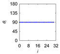
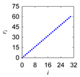
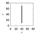
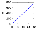
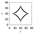
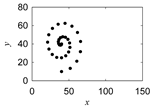
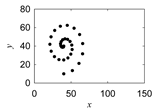
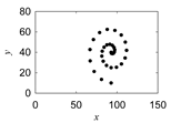
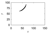
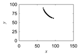
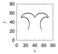
As described before, the four main motifs are Utasa, Morew, Sik, and Ayus. Table 3 shows the point clouds of these motifs and the settings of the instantaneous distances and instantaneous rotational angles. As seen in Table 3, to create the Utasa, two point clouds, one representing a vertical line and the other representing a horizontal line, were needed. To create a point cloud representing a horizontal line, the instantaneous rotational angles were kept constant at zero and the instantaneous distances was increased linearly. On the other hand, to create a point cloud representing a vertical line, the instantaneous rotational angles were kept constant at an angle of 90°, and the instantaneous distances were increased linearly. These two point clouds can be integrated to create the point cloud of Utasa, as shown in the last column in Table 3. Regarding the point cloud of Morew, the instantaneous rotational angles must be increased linearly, and instantaneous distance must be decreased linearly. In this case, a single point cloud was enough to create a model of the motif. Regarding the point cloud of Sik, it was created by integrating four point clouds. For the first point cloud, the instantaneous rotational angles were increased linearly, and the instantaneous distances followed a bathtub like function where the point of inflection was at the middle of the iterations. This point cloud was copied and rotated to create the other three point clouds needed to model Sik. To model the other main motif (Ayus), two point clouds were needed. For one of the point clouds, the instantaneous rotational angles were increased linearly, and the instantaneous distances were first desecrated and then increased nonlinearly in a systematic manner. The other point cloud was created by rotating the first one, as shown in the last column in Table 3.

4.2. Point Cloud of the Synthetic Motifs

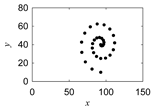
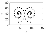
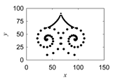
As described before, there are four first-order synthetic motifs, namely, Arus-Morew, Sikike-nu-Morew, Sikike-nu-Morew, and Uren-Morew. Out of these four motifs, two motifs, Uren-morew and Sik-uren-morew, have been selected to show how to create the point clouds of the synthetic motifs from those of the main motifs. This means that the point clouds shown in Table 3 can be used to create the point clouds of these two synthetic motifs. The process of point cloud integration is shown in Table 4. As seen in Table 4, to create the point cloud of the synthetic motif called Uren-morew, two point clouds were used. One of the point clouds was the point cloud of Morew, as shown in Table 3, and the other was its inverted counterpart. On the other hand, to create the model of the synthetic motif called Sik-uren-morew, four point clouds were used. The first two point clouds were the point clouds of Sik and Morew, respectively. These two point clouds were inverted to create the other two point clouds, as shown in Table 4.

4.3. Point Cloud of the Plant Motifs

As described before, there are four plant motifs, namely, Morew-etok, Punkar, Apapo-piras (u) ke, and Apapo-epuy. The point clouds of the two selected motifs, namely, Morew-etok and Apapo, are shown in Table 5. The point clouds of other two can be created using a similar procedure.
As seen in Table 5, two point clouds were integrated to create the point cloud of Morew-etok. For the first point cloud, the instantaneous rotational angles were increased linearly, whereas the instantaneous distances were varied in accordance with a dome-like function. These settings created a point cloud representing a leaf-like shape. The other point cloud, which modeled the tail of Morew-etok, was created by increasing both the instantaneous rotational angles and distances linearly.
Since the motif called Apapo consists of two symmetrical segments, one of the segments was first modeled by two point clouds. For the first point cloud, the instantaneous rotational angles were increased linearly, whereas the instantaneous distances were varied using a concave function with the point inflection at the middle of the iterations. The other point cloud was created by increasing both the instantaneous rotational angles and distances linearly. The two point clouds were integrated. Finally, the integrated point clouds were inverted to create the point clouds of the other half of Apapo. Thus, four individually created point clouds constitute the point cloud of Apapo, as shown at the bottom of the last column in Table 5.

4.4. Virtual and Physical Prototypes of Ainu Patterns

This subsection presents the virtual and physical prototypes of some selected patterns collected from the Hokkaido Ainu community. First, the virtual and physical models of ten selected basic motifs are presented in Table 6. Afterward, the virtual and physical models of three complex motifs are presented in Table 7. All the virtual models were created by inputting the respective point clouds to a commercially available CAD package, as prescribed by the methodology presented in Section 3. The physical models were fabricated by using a 3D printer available at Kitami Institute of Technology.
When Ainu patterned crafted houses, clothing, ornaments, utensils, and spiritual goods are studied, complex patterns are observed, which can be modeled by synthesizing the basic motifs described above. Thus, using the same methodology presented in Section 3, the complex patterns can also be digitalized, as described below.
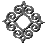
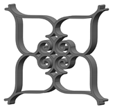
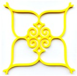
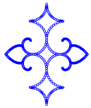
The point clouds of three selected complex patterns, denoted as Model-1, Model-2, and Model-3, as well as their virtual and physical prototypes, are shown in Table 7. Model-1 (the second row in Table 7) is created based on the motif called Sik-uren-morew. As seen in Table 7, Model-1 consists of four pieces of Sik-uren-morew motif. The settings of the instantaneous rotational angles and instantaneous distances to create the point cloud have already been described above. In order to configure Model-1, the point cloud of Sik-uren-morew was rotated three times by 90°, 180°, and 270°, respectively. Afterward, all these point clouds were integrated into a single point cloud, resulting in the complex pattern (Model-1). The point cloud of Model-1 was transferred to a commercially available CAD system to create the virtual prototype (a solid CAD model), which is shown in the second column in Table 7. The triangulation data of the virtual prototype were used to produce the physical prototype using a commercially available 3D printer, as shown in the last column in Table 7. Model-2 (the third row in Table 7) was created by integrating the point clouds of three motifs, namely, Sik-uren-morew, Sik, and Ayus. It has an internal segment and an external segment. In the internal segment, the point clouds of two Sik-uren-morew motifs were placed horizontally, and two point clouds of Sik motif were placed vertically. All four point clouds maintain a symmetry. On the other hand, the external segment consists of four symmetrically integrated point clouds of Ayus. The virtual and the physical prototypes are also shown in Table 7 in the second and the last column, respectively. Model-3 (the last row in Table 7) consists of three different motifs, namely, Uren-morew, Sik, and elliptically shaped motifs. The point clouds of two Uren-morew motifs were placed horizontally in a symmetrical manner. In addition, the point clouds of two Sik motifs were placed vertically in a symmetrical manner. The point clouds of two elliptically-shaped motifs were placed adjacent to the Uren-morew motifs. The virtual and physical prototypes are also shown in Table 7 in the second and the last column, respectively.
Though the presented methodology worked well for the motifs shown in this article, other quantitative analysis of the motifs can be performed to understand their aesthetic nature in a quantitative sense. As such, the methodology can be enriched by incorporating other faculties of thought regarding the free-form curve, e.g., log-aesthetic curve [29,30]. In addition, the data acquisition step of the presented methodology (i.e., the first half of the modeling domain shown in Figure 2) relies on human perception only. In this respect, other aiding technology, e.g., 3D pen-based shape learning technology [31], could be incorporated to enrich the presented methodology. These issues remain open for further research.

5. Concluding Remarks

Although the size of the searchable collection of cultural artifacts is growing very fast, there has been less progress in shape perception and analysis. This gap can be filled if the concept of symmetry is used in the analysis, as well as in the virtual and physical prototyping of aesthetic artifacts with cultural significance. The reason is that the aesthetic artifacts found in all cultural heritages often exhibit symmetrical patterns. The present study makes a contribution in this regard. The salient points of this study are summarized as follows.
(a)
The indigenous people living in the northern part of Japan, known as Ainu, decorate their houses, clothing, ornaments, utensils, and spiritual goods using some unique patterns. Nowadays, goods crafted with Ainu patterns are cherished by many people in Japan and abroad, and different kinds of souvenirs and cultural artifacts carry these patterns, making these significant from both cultural and economic viewpoints.
(b)
The fourteen basic motifs underlying the patterns used by the Ainu community living in Hokkaido are elucidated through literature review.
(c)
The digital technology that can mimic the Ainu pattern-making craftsmanship is presented. It consists of three domains, namely, modeling domain, virtual prototyping domain, and physical prototyping domain. The modeling domain employs an algorithm. The algorithm recursively creates a point cloud to preserve the shape information of a given pattern. From a point cloud, a representative segment of a pattern can be copied several times, keeping the symmetry of the pattern. The virtual prototyping domain uses CAD systems to produce a solid CAD model of the given pattern directly from its point cloud. The physical prototyping domain uses a 3D printer to produce the physical prototype of the given pattern directly from the triangulation data of the solid CAD model.
(d)
Ten basic Hokkaido Ainu motifs and three synthesized motifs were digitized using the presented digital technology. The settings of the parameters to create the respective point clouds are also described elaborately.
(e)
The presented methodology helps avoid all sorts of sophisticated transformations and complicated computations that are needed when a scanning- or image-processing-based digitization technique is used.
(f)
The outcomes of the study help preserve the cultural heritage as well as the craftsmanship underlying complex patterns not limited to Ainu community.

Author Contributions

T.(Tashi) and A.S.U. conceived the idea. T.(Tashi) and A.S.U. developed the methodology. T.(Tashi) built the virtual and physical prototypes. T.(Tashi) and A.S.U. wrote the article. T.(Tashi) and A.S.U. revised the article. A.S.U. administered the research.

Funding

This research was funded by Kitami Institute of Technology.

Acknowledgments

An initial short version of this article was published in the proceedings of the 17th International Conference on Precision Engineering, 12–16 November 2018, Kamakura, Japan (Paper No. B–5–4) and in the Proceedings of the 22nd Asia Pacific Symposium on Intelligent and Evolutionary Systems (IES2018), 20–22 December 2018, Sapporo, Japan, CD–ROM, pp. 13–20.

Conflicts of Interest

The authors declare no conflicts of interest.

References

  1. Pintus, R.; Pal, K.; Yang, Y.; Weyrich, T.; Gobbetti, E.; Rushmeier, H. A Survey of Geometric Analysis in Cultural Heritage. Comput. Graph. Forum 2016, 35, 4–31. [Google Scholar] [CrossRef]
  2. Hann, M. Symbol, Pattern and Symmetry: The Cultural Significance of Structure; Bloomsbury: London, UK, 2013. [Google Scholar]
  3. Li, X.; Yin, Z.; Wei, L.; Wan, S.; Yu, W.; Li, M. Symmetry and template guided completion of damaged skulls. Comput. Graph. 2011, 35, 885–893. [Google Scholar] [CrossRef]
  4. Zhou, P.; Shui, W.; Qu, L.; Gao, F.; Wu, Z. Case study: Missing data computation and 3D printing application in symmetrical artifact restoration. In Proceedings of the Symposium on VR Culture and Heritage, Zhuhai, China, 3–4 December 2016; Volume 2, pp. 63–66. [Google Scholar] [CrossRef]
  5. Fukumoto, I.; Kondo, O. Three-dimensional craniofacial variation and occlusal wear severity among inhabitants of Hokkaido: Comparisons of Okhotsk culture people and the Ainu. Anthr. Sci. 2010, 118, 161–172. [Google Scholar] [CrossRef]
  6. Kura, K.; Armstrong, E.L.; Templer, D.I. Cognitive function among the Ainu people. Intelligence 2014, 44, 149–154. [Google Scholar] [CrossRef] [Green Version]
  7. Nishikiya, T. A Positive Consideration of Ainu pattern. Bull. Jpn. Soc. Sci. Des. 1971, 1971, 49–65. (In Japanese) [Google Scholar] [CrossRef]
  8. Nishikiya, T. Ainu pattern its origin and composition. Bull. Jpn. Soc. Sci. Des. 1971, 1971, 74–75. (In Japanese) [Google Scholar] [CrossRef]
  9. Nishikiya, T. Ainu pattern: Its origin and composition. Bull. Jpn. Soc. Sci. Des. 1970, 1970, 8–9. (In Japanese) [Google Scholar] [CrossRef]
  10. Ogawa, S. Ainu Minzoku Mon’yoshu: Shishu no Sashikata, Tachikata No Sekai, Sapporo-shi: Ainu Bunka Densho no Kai Tezukuri Utara; Hatsubai Karinsha; Sanae Ogawa: Sapporo, Japan, 2010. (In Japanese) [Google Scholar]
  11. Sugiyama, H. On the composition of Ainu pattern. Bull. Jpn. Soc. Sci. Des. 1968, 1968, 60–61. (In Japanese) [Google Scholar] [CrossRef]
  12. Tsuda, N. Ainu Shishu Nyumon; Kuruzu: Sapporo, Japan, 2008. (In Japanese) [Google Scholar]
  13. The Foundation for Ainu Culture. Ainu Living Culture Reproduce Manual. Available online: https://www.ff-ainu.or.jp/ (accessed on 9 April 2019).
  14. Chiba, T. Problems on Making the Landscape Guideline of Facility Complex in Akan National Park; Summaries of Technical Papers of Annual Meeting of the Architectural Institute of Japan; The Architectural Institute of Japan: Tokyo, Japan, 2013; pp. 397–398. (In Japanese) [Google Scholar]
  15. City of Sapporo, Ainu-Siriki. Available online: http://www.city.sapporo.jp/shimin/pirka-kotan/jp/kogei/ainu-siriki/index.html (accessed on 9 April 2019).
  16. Geng, Z.; Bidanda, B. Review of reverse engineering systems—Current state of the art. Virtual Phys. Prototyp. 2017, 13, 1–12. [Google Scholar] [CrossRef]
  17. Ceccarelli, S.; Guarneri, M.; De Collibus, M.F.; Francucci, M.; Ciaffi, M.; Danielis, A. Laser Scanners for High-Quality 3D and IR Imaging in Cultural Heritage Monitoring and Documentation. J. Imaging 2018, 4, 130. [Google Scholar] [CrossRef]
  18. Furferi, R.; Governi, L.; Volpe, Y.; Puggelli, L.; Vanni, N.; Carfagni, M. From 2D to 2.5D i.e. from painting to tactile model. Graph. Models 2014, 76, 706–723. [Google Scholar] [CrossRef]
  19. Hasegawa, K.; Li, L.; Okamoto, N.; Yanai, S.; Yamaguchi, H.; Okamoto, A.; Tanaka, S. Application of Stochastic Point-Based Rendering to Laser-Scanned Point Clouds of Various Cultural Heritage Objects. Int. J. Autom. Technol. 2018, 12, 348–355. [Google Scholar] [CrossRef]
  20. Jo, Y.H.; Hong, S. Three-Dimensional Digital Documentation of Cultural Heritage Site Based on the Convergence of Terrestrial Laser Scanning and Unmanned Aerial Vehicle Photogrammetry. ISPRS Int. J. Geo-Inf. 2019, 8, 53. [Google Scholar] [CrossRef]
  21. Neumüller, M.; Reichinger, A.; Rist, F.; Kern, C. 3D printing for cultural heritage: Preservation, accessibility, research and education, 3D Research Challenges in Cultural Heritage. Lect. Notes Comput. Sci. 2014, 8355, 119–134. [Google Scholar] [CrossRef]
  22. Reichinger, A.; Carrizosa, H.G.; Wood, J.; Schröder, S.; Löw, C.; Luidolt, L.R.; Schimkowitsch, M.; Fuhrmann, A.; Maierhofer, S.; Purgathofer, W. Pictures in your mind: Using interactive gesture-controlled reliefs to explore art. ACM Trans. Access. Comput. 2018, 11, 1–39. [Google Scholar] [CrossRef]
  23. Scopigno, R.; Cignoni, P.; Pietroni, N.; Callieri, M.; Dellepiane, M. Digital fabrication techniques for cultural heritage: A survey. Comput. Graph. Forum 2017, 36, 6–21. [Google Scholar] [CrossRef]
  24. Soler, F.; Melero, F.J.; Luzón, M.V.; Rus, F.J.M. A complete 3D information system for cultural heritage documentation. J. Cult. Herit. 2017, 23, 49–57. [Google Scholar] [CrossRef]
  25. Tashi; Ullah, A.S.; Watanabe, M.; Kubo, A. Analytical Point-Cloud Based Geometric Modeling for Additive Manufacturing and Its Application to Cultural Heritage Preservation. Appl. Sci. 2018, 8, 656. [Google Scholar] [CrossRef]
  26. James, D.W.; Belblidia, F.; Eckermann, J.E.; Sienz, J. An innovative photogrammetry color segmentation based technique as an alternative approach to 3D scanning for reverse engineering design. Comput. Aided Des. Appl. 2017, 14, 1–16. [Google Scholar] [CrossRef]
  27. Tamaki, J.; Yanagi, S.; Aoki, Y.; Kubo, A.; Kameda, T.; Ullah, A.M.M.S. 3D Reproduction of a Snow Crystal by Stereolithography. J. Adv. Mech. Des. Syst. Manuf. 2012, 6, 923–935. [Google Scholar] [CrossRef] [Green Version]
  28. Rojas-Sola, J.I.; Galán-Moral, B.; De la Morena-De la Fuente, E. Agustín de Betancourt’s Double-Acting Steam Engine: Geometric Modeling and Virtual Reconstruction. Symmetry 2018, 10, 351. [Google Scholar] [CrossRef]
  29. Inoguchi, J.; Ziatdinov, R.; Miura, K.T. Generalization of log-aesthetic curves via similarity geometry. Japan J. Ind. Appl. Math. 2019, 36, 239–259. [Google Scholar] [CrossRef]
  30. Sato, M.; Shimizu, Y. Generalization of log-aesthetic curves by Hamiltonian formalism. JSIAM Lett. 2016, 8, 49–52. [Google Scholar] [CrossRef]
  31. Okubo, M.; Mizuno, Y. Influence of interactive learning support system using augmented reality on 3D object drawing. J. Adv. Mech. Des. Syst. Manuf. 2018, 12. [Google Scholar] [CrossRef]
Figure 1. Ainu patterned crafted house, clothing, and other goods.
Symmetry 11 00985 g001
Figure 2. Pattern digitization methodology.
Symmetry 11 00985 g002
Figure 3. The working principle of the point cloud creation algorithm.
Symmetry 11 00985 g003
Table 1. Basic motifs used by the Ainu community living in Hokkaido [15].
No.MotifNameNo.MotifsNames
1 Symmetry 11 00985 i001Ayus8 Symmetry 11 00985 i002Ski-uren-morew
2 Symmetry 11 00985 i003Morew8 Symmetry 11 00985 i004Morew-etok
3 Symmetry 11 00985 i005Arus-morew10 Symmetry 11 00985 i006Punkar
4 Symmetry 11 00985 i007Sikike-nu-morew11 Symmetry 11 00985 i008Apapo-piras(u) ke
5 Symmetry 11 00985 i009Sik12 Symmetry 11 00985 i010Apapo-epuy
6 Symmetry 11 00985 i011Utasa13 Symmetry 11 00985 i012-
7 Symmetry 11 00985 i013Uren-morew14 Symmetry 11 00985 i014-
Table 2. Gradual creation of a point cloud.
iInputsOutputs (PC)
riθi
10 Symmetry 11 00985 i015 Symmetry 11 00985 i016 Symmetry 11 00985 i017
15 Symmetry 11 00985 i018 Symmetry 11 00985 i019 Symmetry 11 00985 i020
16 Symmetry 11 00985 i021 Symmetry 11 00985 i022 Symmetry 11 00985 i023
20 Symmetry 11 00985 i024 Symmetry 11 00985 i025 Symmetry 11 00985 i026
30 Symmetry 11 00985 i027 Symmetry 11 00985 i028 Symmetry 11 00985 i029
Table 3. Point clouds and the settings of the instantaneous distances and instantaneous rotational angles of the main motifs of Hokkaido Ainu.
Main MotifsInstantaneous Rotational AngleInstantaneous DistanceSegment-Wise Point Clouds (PC)Integrated Point Cloud
Utasa Symmetry 11 00985 i030 Symmetry 11 00985 i031 Symmetry 11 00985 i032 Symmetry 11 00985 i033
Symmetry 11 00985 i034 Symmetry 11 00985 i035 Symmetry 11 00985 i036
Morew Symmetry 11 00985 i037 Symmetry 11 00985 i038 Symmetry 11 00985 i039
Sik Symmetry 11 00985 i040 Symmetry 11 00985 i041 Symmetry 11 00985 i042 Symmetry 11 00985 i043
Ayus Symmetry 11 00985 i044 Symmetry 11 00985 i045 Symmetry 11 00985 i046 Symmetry 11 00985 i047
Table 4. Point clouds of two selected synthetic motifs of Hokkaido Ainu.
Synthetic MotifsPoint Cloud(s) of Main Motif(s)Inverted Point Cloud(s)Integrated Point Clouds
Uren-morew Symmetry 11 00985 i048 Symmetry 11 00985 i049 Symmetry 11 00985 i050
Sik-uren-morew Symmetry 11 00985 i051 Symmetry 11 00985 i052 Symmetry 11 00985 i053
Symmetry 11 00985 i054 Symmetry 11 00985 i055
Table 5. Point clouds and the settings of the instantaneous distances and instantaneous rotational angles of two selected plant motifs of Hokkaido Ainu.
Motif NameInstantaneous Rotational AngleInstantaneous DistanceSegment-Wise Point Cloud (PC)Integrated Point Cloud
Morew-etok Symmetry 11 00985 i056 Symmetry 11 00985 i057 Symmetry 11 00985 i058 Symmetry 11 00985 i059
Symmetry 11 00985 i060 Symmetry 11 00985 i061 Symmetry 11 00985 i062
Apapo Symmetry 11 00985 i063 Symmetry 11 00985 i064 Symmetry 11 00985 i065 Symmetry 11 00985 i066
Symmetry 11 00985 i067 Symmetry 11 00985 i068 Symmetry 11 00985 i069 Symmetry 11 00985 i070
Table 6. Virtual prototypes of the motifs listed in Table 1.
Virtual ModelsPhysical ModelsVirtual ModelsPhysical Models
Symmetry 11 00985 i071 Symmetry 11 00985 i072 Symmetry 11 00985 i073 Symmetry 11 00985 i074
AyusSik-uren-morew
Symmetry 11 00985 i075 Symmetry 11 00985 i076 Symmetry 11 00985 i077 Symmetry 11 00985 i078
MorewMorew-etok
Symmetry 11 00985 i079 Symmetry 11 00985 i080 Symmetry 11 00985 i081 Symmetry 11 00985 i082
SikPunkar
Symmetry 11 00985 i083 Symmetry 11 00985 i084 Symmetry 11 00985 i085 Symmetry 11 00985 i086
UtasaApapo-piras(u) ke
Symmetry 11 00985 i087 Symmetry 11 00985 i088 Symmetry 11 00985 i089 Symmetry 11 00985 i090
Uren-morewApapo-epuy
Table 7. Virtual and Physical prototyping of three complex patterns.
Model-Point CloudsVirtual PrototypesPhysical Prototypes
1 Symmetry 11 00985 i091 Symmetry 11 00985 i092 Symmetry 11 00985 i093
2 Symmetry 11 00985 i094 Symmetry 11 00985 i095 Symmetry 11 00985 i096
3 Symmetry 11 00985 i097 Symmetry 11 00985 i098 Symmetry 11 00985 i099