Article

Is Handedness Information Critical for Discriminating Figure Pairs?

Faculty of Education, Hakuoh University 1117 Daigyoji, Oyama, Tochigi 323-8585, Japan
Symmetry 2019, 11(5), 624; https://doi.org/10.3390/sym11050624
Submission received: 28 February 2019 / Revised: 25 April 2019 / Accepted: 25 April 2019 / Published: 3 May 2019
(This article belongs to the Special Issue Visual Symmetry 2018)

Abstract

:
Mirror-reflected or axisymmetric (Ax) pairs of figures are known to be difficult to discriminate. If non-identical pairs of figures with specific feature values impede discrimination to the same extent as the discrimination of Ax pairs, the feature values concerned would be expected to cause discrimination difficulty and may be critical for figure recognition in general. In the present study, we examined whether handedness information (i.e., the left or right side of a disoriented figure) is critical for the discrimination of figure pairs with pairs of complex figures (Experiment 1) and simpler figures (Experiment 2). Participants performed a task requiring discrimination of whether the figures in a pair had the same shape regardless of orientation. Three basic pair types were prepared: identically shaped pairs, Ax pairs, and non-identical, non-axisymmetric (Nd) pairs. Non-axisymmetric pairs were further classified into same-handedness pairs and opposite-handedness pairs. The results revealed that discrimination latencies were longer for Ax pairs than for both same-handedness pairs and opposite-handedness pairs. These findings suggest that handedness information is not a critical feature in figure recognition.

1. Introduction

Shepard and Metzler [1] reported that latencies for making same/different decisions about simultaneously presented pairs of rotated but identically shaped objects increased linearly with the angular distance between the two objects in three-dimensional space within the range of 0° to 180°. Because this linearity of latencies was evident across stimuli and participants, the researchers assumed that the process of making identity decisions about the rotated objects involved “mental rotation in three-dimensional space” (p. 703). This assumption implies that the recognition of rotated objects is on the basis of the non-analytical process of normalization by rotation. In contrast, Corballis [2] proposed that people recognize a figure by extracting its coordinate-independent descriptions (later defined as invariant features) which could be used for its identification regardless of its orientations or of outline deformation (e.g., the letter “A” could be identified as such because of having a closed sequence of three line segments attached with roughly codirected two line segments even when its size, orientation, and aspect ratio are modestly altered).
More detailed examinations of the phenomenon of mental rotation has revealed that the slopes of the latencies against the angular distances between the two disoriented figures of identical pairs vary according to the experimental conditions. Mental rotation slopes are generally steep for complex stimuli, including Shepard’s block figures [1], stimuli involving extended blocks of Shepard’s figures [3], random polygons with varied numbers of flections [4], and complex random matrices [5]. The slopes for these stimuli are typically >20 ms/°. However, for normal versus mirror-reflected decisions about memorized letter-like symbols [6], memorized Shepard’s blocks [7], and memorized random polygons [8], slopes are reported to be in the rage of 1 ms/° and 5 ms/°. These results indicate that mental rotation is involved in the recognition of both 3D and 2D stimuli. As a reference, Cohen and Kubovy [9] claimed that slopes shallower than 1 ms/° are thought to be too shallow for mental rotation to occur.
Another group of tasks that might be associated with increased slope are tasks requiring same/mirror-reflected discriminations of unfamiliar stimuli [1,10,11]. Förster, Gebhardt, Lindlar, Siemann, and Delius [12] presented participants with triplets of random polygons and instructed them to choose which of the flanking polygons were identical in shape to the central polygon regardless of its orientation. The results revealed that the slopes for discriminating mirror-reflected polygons were similar to slopes for polygons that were difficult to discriminate. The researchers suggested that mirror-reflected stimuli may be a special case of hard-to-discriminate stimuli.
Regarding the recognition of mirror-reflected figures, Corballis [2] proposed that mental rotation would be necessary if the recognition of a figure requires either the discrimination from its mirror-reflected counterpart regardless of its orientation or the discrimination of its left side from the right side (i.e., handedness) [13,14].
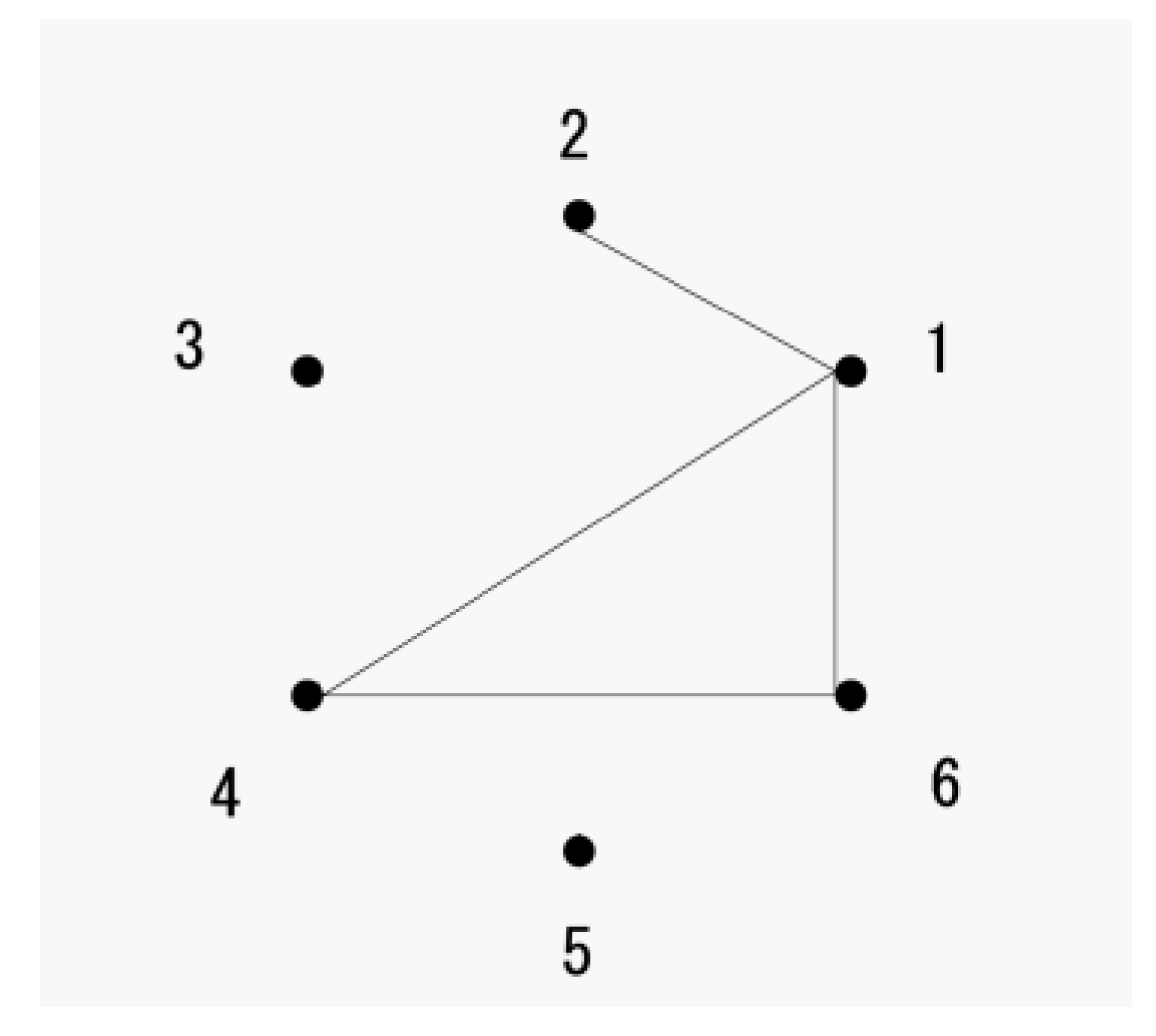
In the current study, (6 point, n line) figures (or a (6, n) figure) were used as stimuli for the figure recognition experiments. A (6, n) figure consists of n line segments, each of which is connected between a distinct pair of points located at the vertices of a regular hexagon (Figure 1). According to graph theory, if the line segments connecting n pairs of points in one figure are identical to those connecting n pairs of points in another figure, regardless of the locations of the points, the two figures are mutually isomorphic [15].
For clarity, in the current study, a descriptive element (or property) of a figure is hereafter referred to as a feature. Features can be classified into two categories: (a) features describing structural aspects of a figure (invariant features), and (b) features describing non-structural aspects (superficial features). Here, the definition of invariant features was based on the definition of graph invariants [15]. Among an isomorphic set of figures, all invariant feature values are the same, and only the values of superficial features differ. It must also be noted in the more general setting of graphons, this is still true. Importantly, two figures of an identically shaped pair as well as those of a mirror-reflected pair are both mutually isomorphic. In the current study, identical figure pairs, regardless of their orientation, are hereafter referred to as rotated-to-be-identical (Idr) pairs, and mirror-reflected pairs are referred to as axisymmetric (Ax) pairs.
The latencies required to discriminate non-identical, non-axisymmetric (Nd) pairs are generally shorter than the latencies required to identify Idr pairs [16,17,18,19]. This phenomenon could be interpreted as indicating that feature values of an Nd pair of figures are more varied compared with those of an Idr pair, and their value differences would be readily available in cases where the decision “different” is made. Specifically, it has been reported that detection of a difference in invariant feature values is prioritized compared with detection of a difference in superficial feature values [17,20]. Although Ax pairs are a special case of Nd pairs, the latencies for Ax pairs tend to be longer than those for Idr pairs [18,19].
Because there is no difference in invariant feature values between Idr and Ax figure pairs, it is important to understand differences in how the values of superficial features behave between the two pair types. The shapes are the same for the two figures of an Idr pair. Thus, there is no difference in corresponding line lengths and included angles between the two figures. In addition, such superficial feature values, either a clockwise or counterclockwise direction from one base location to a specific location in one figure, are identical to the direction from the base location to the corresponding location in the other figure, and the shortest angular distances from respective locations of one figure to the corresponding locations of the other figure are constant when the centers of the two figures are superposed. Regarding Ax pairs, the corresponding line lengths and included angles are the same as those in an Idr pair, but the direction from one base location to another location by the shortest angular distance in one figure is opposite to the corresponding direction in the other figure, except for the angular distance between the two locations, which is 180° in both figures. Moreover, the shortest angular distances from respective locations of one figure to the corresponding locations of the other figure are twice the distance from a location to an axis of symmetry in one figure when the centers of the two figures are superposed.
Thus, two superficial features could cause the difficulty for Ax pairs: difficulty detecting a difference in the clockwise or counterclockwise direction from a base location to another location between the two figures of a pair and difficulty detecting a difference in the shortest angular distances from respective locations of one figure to the corresponding locations of the other figure.
In the current study, information concerning either a clockwise or counterclockwise direction from the location of a base point to the location of another point by the shortest angular distance in a figure was referred to as the handedness of the location [21], and the angular distances between the corresponding locations of two figures of a pair, either in a clockwise or a counterclockwise direction, when the centers of the two figures are superposed, were referred to as a shift of locations. In short, the lengths, angles, and respective handedness were all identical, and the shifts of locations were all constant for an Idr pair. In contrast, the lengths and angles were identical, but respective handedness was mainly opposite, and the shifts of locations were variable for an Ax pair. Figure 2 shows the characteristics of the superficial features of handedness and shifts in Idr and Ax pairs.
In an earlier study by the author [18], it was presumed that complex shifting patterns of locations caused the discrimination of the two figures of an Ax pair to be difficult. Specifically, it was hypothesized that discrimination latencies of Nd pairs would become similar to those of Ax pairs when both types of pairs had the same extent of complexity in the shifting pattern of invariant feature locations. In a task used to determine whether a presented pair of figures were identical in shape regardless of their orientation, three main types of (6, 5) figure pairs were prepared: Idr, Ax, and mutually isomorphic Nd pairs.
In each figure, the locations of four invariant features (i.e., an endpoint, a cycle, an isolated point, and maximum degree point) were calculated. Concerning Nd pairs, they were further categorized according to the extent of deviation from a constant shift of four invariant locations of one figure to the other figure in a pair: Nd 1/4, Nd 2/4, and Nd 4/4 pairs with the numerators indicating the number of the deviant locations from a constant shift. Axisymmetric (Ax) pairs with their number of deviations from a constant shift other than 2/4 were discarded from the stimuli, and thus, Ax pairs were all Ax 2/4 pairs. The results revealed that the latencies were significantly different between every pair with an ascending order as Nd 4/4, Nd 2/4, Nd 1/4, Idr, and Ax 2/4 pairs. The results, thus, did not support the hypothesis that the complex shifting pattern of invariant feature locations in Ax pairs alone caused the difficulty in distinguishing Ax pairs.
The current study sought to examine the importance of handedness of figure pairs in the recognition of figures. Provided that the lack of sensitivity to opposite handedness between the two figures of Ax pairs causes difficulties in discrimination, it was hypothesized that the discrimination difficulty of non-identical pairs with opposite handedness would be critical in the discrimination difficulty of Ax pairs. Three pair types were generated: Idr, Ax, and Nd pairs. And Nd pairs were further classified into two categories: pairs in which two figures had the same handedness (Nd sm) and pairs in which two figures had opposite handedness (Nd op).
Previous studies reporting the importance of handedness information for the occurrence of mental rotation have tended to use familiar stimuli such as disoriented (b versus d) and (p versus q) decisions [14] or left versus right side decisions about an asterisk in a nearby disoriented letter [22]. The stimuli in these studies were overlearned, and handedness information was stereotypically presented to participants. In contrast, the present stimuli were randomly generated, and the presentation of handedness information varied from trial to trial. Thus, the current results could be more generalizable.
Given the evidence suggesting that the detection of differences in invariant feature values is prioritized over the detection of differences in superficial features [17,20,23], all stimulus figure pairs were set to be mutually isomorphic to prevent the effect of invariant features being confounded with the effect of handedness. Because some researchers have insisted that the presence of intersections of line segments are detected preattentively [24], figures with one or more intersections of line segments were discarded from the stimulus figures.
Several previous studies indicated that the presence of closure is critical in figure recognition [16,25,26], while Julesz [27] claimed that line terminators (i.e., endpoints) were detected at an early stage of figure recognition. Thus, figures consisting of a cycle and endline(s) were selected as stimulus figures. The number of lines incident with a point is referred to as the degree of the point [15]. An endpoint is a point whose degree is 1 (also called a pendant vertex [28]), an endline is a line segment with at least one endpoint at its ends, and a cycle is a closed sequence of points and line segments that starts and ends at the same point. Finally, handedness is defined here as either a clockwise or counterclockwise direction from a maximum degree point to an endpoint.

2. Experiment 1

Pairs of figures belonging to three isomorphic sets of (6, 5) figures were selected as stimuli, which commonly had a cycle connected with one or two endlines (Figure 3). Figures belonging to isomorphic set a had two endlines connected with a triangle at one point. Figures belonging to set b commonly had two endlines connected with a triangle at two different points. Figures in set c commonly had a quadrilateral and an endline connected at one point.

2.1. Methods

2.1.1. Stimuli

A pair of (6, 5) figures was presented on a NEC AS171MC LCD monitor as a stimulus. The monitor was controlled by a NEC MJ33AA-9 microcomputer. By using the pair generation procedures described below, all stimuli were prepared. The response speed of the monitor was 5 ms, and the timing of the stimulus presentation was about 1 ms. The vertices of an invisible regular hexagon were stylized as filled circles with a diameter of 0.4 cm. The locations of their centers were shifted 0.2 cm outward from the invisible vertices. The shortest line segments were 3.8 cm and the longest segments were 7.6 cm. Their visual angles were 3.34° and 6.69°, respectively. Excluding the stylized points, the width and height of the stimulus presentation area were 6.6 cm and 7.6 cm, respectively. Both line segments and the stylized points were presented in the experiment. Two figures of a stimulus were presented simultaneously at horizontally parallel positions. The between-centers distance of the figures was 9.4 cm.

2.1.2. Generation of Stimulus Pairs

Pairs were independently prepared for each participant. From a total of 3003 (6, 5) figures, only the figures belonging to the three isomorphic sets a, b, and c were selected and pooled as candidates for stimulus figures. Figures having one or more intersecting line segments were discarded from the pool of candidate figures. All of the candidate figures within a given isomorphic set were combined to form figure pairs. Each pair was examined in terms of whether the two figures were identical in shape with an angular distance of 0°, 60°, 120°, 180°, 240°, or 300°. If the figures matched, they were classified as an Idr pair and pooled. Otherwise, it was determined whether the figures were axisymmetric with their axis of symmetry being 0°, 30°, 60°, 90°, 120°, or 150°. If they were axisymmetric, they were classified as an Ax pair and pooled. Otherwise, they were classified as an Nd pair. Then, Nd pairs were further subclassified according to their handedness. Handedness was determined by whether the direction from a maximum degree point to an endpoint was clockwise or counterclockwise. Concerning the figures belonging to sets a and b, the respective handedness of two endlines could be either the same or different. If a pair of figures had different handedness in one figure regardless of the states of handedness in the other figure, it was difficult to classify a pair as either the same handedness or different handedness. To discard indeterminate handedness pairs, the following procedure was applied. If the shortest angular distance between the two locations was either 60° or 120° clockwise, +1 was considered the handedness value, and if the shortest angular distance between the two locations was 180° clockwise, a handedness value of 0 was determined. In contrast, if the shortest angular distance between the two locations was 60° or 120° counterclockwise, a handedness value of −1 was determined, and if the distance was 180° counterclockwise, a value of 0 was determined. If a figure had one endline (i.e., isomorphic set c) the obtained handedness value represented the figure’s handedness. If a figure had two endlines (i.e., isomorphic sets a and b) the summation of handedness values represented the figure’s handedness. If the signs of the handedness values of two figures were the same, the pair was determined as an Nd sm pair and pooled, and if the signs were opposite, the pair was determined as an Nd op pair and pooled. If at least one of the handedness values was 0, the pair was discarded. For each participant, 160 pairs were randomly sampled from the Idr, 40 pairs from the Nd sm, 40 pairs from the Nd op, and 80 pairs from the Ax pools to prepare a set of test pairs. Figure 4 gives examples of pairs in each category. Each sampled set of Idr, Nd sm, Nd op, and Ax test pairs was next divided into two subsets. Each pair type of one of the subsets was then concatenated into a set of test pairs for one block. Also, each pair type of the remaining subset was also concatenated into another set of test pair for the other block. For each subset the pair presentation order across pair types were randomized. Likewise, 12 practice pairs were randomly selected from the Idr, Nd sm, Nd op, and Ax pools and were divided into two subsets, and the presentation orders of the respective subsets were randomized. Finally, one subset of practice pairs and one subset of test pairs were concatenated to constitute a set of pairs for the first block of trials, and the remaining subsets of practice pairs and test pairs were concatenated to constitute a set of pairs for the second block of trials. Therefore, two blocks of test trials were given to each participant who made 160 test trials in each of the block.

2.1.3. Procedures

Each participant was instructed to judge whether a presented pair of figures was the “same” or “different” in shape regardless of the orientations of the figures. Participants communicated their decision by pushing a button on a switch box. On the switch box, three buttons were horizontally, and when viewed from left to right, were labeled “Enter”, “F6”, and “F5”. Participants used their index finger to push the F6 button and used their middle finger to push the F5 button for making decisions. Two blocks of pairs were presented to each participant according to the function assigned to the F6 and F5 buttons. Across the blocks the functions of the buttons alternated. This alternation of button function served to counterbalance possible differences in finger-specific response speed between the two fingers. Each participant received instructions concerning which button “F5” or “F6” to press to indicate that the figures were the “same” or “different” at the start of each block. The participants were explicitly told that Ax pairs were different pairs. Additionally, participants were asked to maximize both speed and accuracy when making their responses. Each participant placed their head on a chinrest which was located 60 cm from the monitor. Each trial started with a “ready” message appeared on the screen. When pushing the “Enter” button, the message cleared followed by a blank screen for 2.5 s. Accompanied by a beep, a fixation cross appeared for 0.5 s at the center of the screen. Then, it was replaced by a pair of stimulus figures. Each trial was a sequence of events started with pushing the Enter button and ended with a response. A block of trials consisted of six practice trials and 160 test trials. While the participants received an immediate feedback message regarding the correctness of each response in the practice trials, they received no feedback in the test trials. The response latency was defined as the time that elapsed from the presentation of a stimulus to a response made by the participant.

2.1.4. Participants

Four male and eight female university students aged 19–21 years voluntarily took part in the experiment one at a time. All participants had normal or corrected-to-normal vision.

2.1.5. Ethics

This study was approved by the Hakuoh University Ethics Committee.

2.2. Results

The trials with latencies more than 10,000 ms were taken as outliers (0.3% of all trials) and were excluded from the following analyses. The latencies of erroneous decisions were also not included in the analyses. Figure 5 shows the mean latencies and error rates of the three pair types. A Kruskal–Wallis test revealed that the error rates were significant, H = 9.4, p < 0.05. Multiple comparisons using a Steel–Dwass test indicated that the difference in error rates was only significant between Nd op and Nd sm pairs, p < 0.05. An analysis of variance (ANOVA) of latencies showed a significant effect of pair types, F (3, 33) = 24.7, p < 0.001, and η2 = 0.18. Scheffe’s multiple comparisons test revealed that the differences between Idr and Nd sm pairs, Idr and Nd op pairs, and Nd sm and Nd op pairs were not significant, ps > 0.05, while differences between Idr and Ax, Nd sm and Ax, and Nd op and Ax pairs were significant, ps < 0.01.
Mean latencies and error rates at the respective angular distances in Idr pairs are shown in Figure 6. A linear regression analysis for the latencies against the angular distances (folded at 180°) in Idr pairs showed that the coefficient was significant, B = 8.42 ms/°, F (1, 70) = 16.5, p < 0.001, and r2 = 0.19. Figure 7 shows the latencies and error rates for the six axes of symmetry in Ax pairs. Each axis of symmetry was expressed according to the counterclockwise angular distance from the horizontal axis. An ANOVA revealed that the effects of axes of symmetry on latencies were not significant, F (5, 55) = 2.14, p > 0.05, and η2 = 0.02.

2.3. Discussion

Because there was no obvious speed–accuracy trade-off relationship, the following interpretation refers only to latencies. The longer latencies for Ax pairs compared with Nd op pairs did not support the hypothesis that the lack of sensitivity to opposite handedness causes difficulty in discriminating Ax pairs. Rather, the lack of performance difference between Nd sm and Nd op pairs indicated that participants were not sensitive to handedness information as a whole, and that handedness may not be a critical superficial feature.
Because the stimulus pairs were all mutually isomorphic, correct discrimination must be based on the detection of a difference in superficial feature values between the two figures in the Nd pair. The values of superficial features are more varied in complex figures, as in the case of (6, 5) figures, and more varied values would be expected to lead to non-identical decisions. In this respect, shorter latencies for both types of Nd pairs than for Ax pairs would indicate that accidental differences in superficial feature values other than handedness contribute to the faster decisions in response to Nd pairs than to Ax pairs.
Although it was not the principal purpose of the experiment, the significant linear regression coefficient indicated that mental rotation occurred. In addition, the latencies for Ax pairs with the vertical axis of symmetry were visibly shorter than those of other axes of symmetry, as reported in a previous study by the author [19] but did not reach statistical significance in the present experiment.

3. Experiment 2

Because the latencies for Ax pairs were significantly longer than those for Nd op pairs in Experiment 1, the importance of opposite handedness as the cause of discrimination difficulty for Ax pairs was not substantiated. However, it is possible that differences in superficial feature values other than opposite handedness facilitated negative identity decisions for Nd pairs. The possibility of such confusion would be expected to be greater in complex figure pairs. In addition, stimulus figures belonging to isomorphic sets a and b had two endlines attached to a triangle. If a stimulus figure had two endlines, the handedness of two endlines of a figure was either the same or opposite, which could induce ambiguity to the definition of the handedness of a figure as a whole. Taking these possibilities into account, Experiment 2 used simpler (6, 4) figure pairs as stimuli. To remove ambiguity from the definition of handedness, an isomorphic set of figures was chosen, which commonly consists of a triangle and an endline connected at one point. Furthermore, even if the angular distance between an endpoint and a maximum degree point is 180° in a figure, the handedness of an endpoint can still be determined with reference to the shortest angular distance from the locations of non-maximum degree points of a triangle (see Figure 8). The figures with an intersection of line segments were discarded from candidate figures as in Experiment 1.

3.1. Methods

3.1.1. Stimuli

Stimuli were identical to those used in Experiment 1 with the exception that a pair of (6, 4) figures was presented as a stimulus on a 17-inch LCD monitor (NEC AS172MC) controlled by an NEC MJ37LBN15SN microcomputer. The monitor and microcomputer were comparable to the equipment used in the previous experiment, except that the computer had no sound system. Both line segments and the stylized points were presented in the experiment.

3.1.2. Generation of Stimulus Pairs

The process for the generation of pairs was identical to that used in Experiment 1, except for the following points. If the shortest angular distance from a maximum degree point to an endpoint of a figure was either 60° or 120° clockwise, its handedness was considered clockwise, and if the shortest angular distance from a maximum degree point to an endpoint was either 60° or 120° counterclockwise, its handedness was considered counterclockwise. If the angular distance of the two points was 180°, and if the shortest angular distance from a non-maximum degree point of a triangle to an endpoint was less than 180° clockwise, its handedness was considered counterclockwise. In addition, if the angular distance from a non-maximum degree point of a triangle to an endpoint was less than 180° counterclockwise, its handedness was considered clockwise. If the handedness of two figures was the same, the pair was considered an Nd sm pair, and if the handedness was opposite, the pair was considered an Nd op pair. To prepare a set of test pairs for each participant, 180 pairs were randomly selected from the Idr pool, 60 pairs were randomly selected from the Nd sm pool, 60 pairs were randomly selected from the Nd op pool, and 60 pairs were randomly selected from the Ax pool. Likewise, 10 practice pairs were randomly selected from the Idr, Nd sm, Nd op, and Ax pools. Therefore, two blocks of test trials were given to each participant who made 180 test trials in each of the block. Figure 9 shows examples of pairs in each category.

3.1.3. Procedures

The procedures were identical to those of Experiment 1, but no beep sound accompanied the fixation cross.

3.1.4. Participants

Six male and four female university students aged 19–21 years were paid 1000 yen (approximately 9 USD) for their participation. All participants had normal or corrected-to-normal vision.

3.1.5. Ethics

This study was approved by the Hakuoh University Ethics Committee.

3.2. Results

Figure 10 shows the mean latencies and error rates of the three pair types. A Kruskal–Wallis test revealed that the error rates were significant, H = 9.8, p < 0.05. Multiple comparisons using a Steel–Dwass test indicated that the difference in error rates was only significant between Idr and Nd op pairs, p < 0.05. Although the overall error rate was the highest for Ax pairs and the lowest for Nd op pairs, the difference was not significant because of large individual differences in performance for Ax pairs (i.e., participants’ percentage of errors varied from 1.6% to 88%). An ANOVA of latencies revealed a significant effect of pair types, F (3, 27) = 35.2, p < 0.0001, and η2 = 0.53. Scheffe’s multiple comparisons test indicated no significant differences between Idr and Nd op pairs (p > 0.05) or between Nd sm and Nd op pairs (p > 0.999), while significant differences were found between Idr and Nd sm pairs (p < 0.05) as well as Idr and Ax, Nd sm and Ax, and Nd op and Ax pairs (ps < 0.0001). A linear regression analysis for the latencies against the angular distances (folded at 180°) in Idr pairs revealed a significant coefficient, B = 12.02 ms/°, F (1, 58) = 24.0, p < 0.0001, and r2 = 0.29. An ANOVA revealed that the axes of symmetry had no effect on latencies, F (5, 40) = 1.94, p > 0.05, and η2 = 0.10.

3.3. Discussion

Significantly longer latencies for Ax pairs than for Nd op pairs were again obtained even using simpler (6, 4) figure pairs as stimuli. This finding provided no support for the hypothesis that difficulty in detecting opposite handedness causes discrimination difficulty for Ax pairs. The lack of significant differences in latencies between Nd sm and Nd op pairs suggests that handedness information did not affect participants’ identity decisions. The linear regression coefficient of latencies against the angular distances was significant, suggesting that mental rotation occurred. The results revealed no significant effects of the vertical axis of symmetry on the recognition of Ax pairs.

4. General Discussion

Because the latencies for Nd op pairs were shorter than those for Ax pairs, but no latency difference was found between Nd op and Nd sm pairs in the two experiments, handedness information did not appear to be a critical superficial feature for figure recognition. The difficulty in discriminating Ax pairs from Idr pairs supports this conclusion because figures of Idr pairs have the same handedness, but figures of Ax pairs had opposite handedness.
Thus, other superficial features may play a critical role in discriminating mutually isomorphic pairs of figures. As mentioned in the Introduction, the lengths of respective line segments and the angles formed by any two adjacent line segments were identical both for Idr and Ax pairs. In contrast, no experimental control was applied to the lengths of line segments for both types of Nd pairs during the process of pair generation in the current experiments. Thus, the lengths of endlines and the shapes of a cycle (i.e., a triangle or a rectangle) could be different between the two figures of Nd pairs. It is likely that participants made use of superficial feature differences, such as the shapes of the cycle and differences in endline lengths, to discriminate the figures of Nd pairs. In a previous study by the author [19], when equalizing the total lengths of triangles between the two (6, 4) figures in Nd pairs, the latencies to reject identities in Nd pairs of figures with the same endline length became almost equal to those for Ax pairs. Because any triangles existing in (6, n) figures with an equal total length have either the same or axisymmetric shapes, the result strongly suggests that line length is a critical superficial feature in figure recognition. However, the length of a line segment is constrained by a pair of points between which the segment spans. The angle formed between two adjacent line segments is also constrained by two pairs of points, and thus, the lengths and angles are confounded. It will be necessary for future studies to examine the importance of lengths and angles independently without the two variables confounding each other.
The present study was designed on the basis of the premise that the detection of invariant features precedes the detection of superficial features in figure recognition [17,20]. This raises the question of which superficial features are critical in discrimination of figures when figures share the same invariant feature values. Several superficial features could potentially play this role, including the location, distance (or length), angle, direction, and shape of a figure. One previous study by the author [18] suggested that shifting patterns of feature locations were not critical. The present study also indicated that participants were neither sensitive to nor attaching importance to the direction of feature locations (or handedness) for the discrimination of non-identical pairs. Moreover, another study by the author [19] revealed that differences in the lengths of a line segment could be critical in the discrimination of figures. However, line length was confounded by angle. In addition, the shapes of cycles (specifically quadrilaterals) were found to be easily discriminable [20]. Based on these previous findings and the current results, I propose that the abstract (invisible) relationships between feature locations (e.g., shifting patterns and handedness) do not play a critical role in figure recognition, whereas concrete (visible) relationships between feature locations (e.g., the length of a line segment) appear to play a critical role. A small number of cycles may be interpreted as well-known closed shapes rather than closed sequences of line segments with specific lengths. At the same time, it should be noted that some superficial feature values could be critical in the discrimination of figures, although the robustness of discriminability of superficial features may be less than that of invariant features.
Despite the claim by Corballis [12] that mental rotation must be induced to determine the handedness of a given figure, the current results indicated that participants’ sensitivity to handedness was weak. However, the current results indicated that mental rotation did occur when identification of Idr pairs was required. Mental rotation is thought to constitute internal processes and representations that are analogous to the external operations and objects [7]. Thus, mental rotation is essentially a continuous process of recognizing figures by matching a transformed image of an object with the object’s percept. However, there is substantial evidence that people make use of invariant and superficial feature value differences for the discrimination of figures [17,18,19,20]. Thus, it is theoretically necessary to reconcile the distinct characteristics of the non-analytical mental rotation hypothesis and the analytical feature comparison hypothesis, which may coexist in the processes underlying figure recognition.

Funding

This research received no external funding.

Acknowledgments

The author thanks an anonymous reviewer for their comments on the relevancy of the present article to graphons and on the reference to Reference [28], and Benjamin Knight, from Edanz Group (www.edanzediting.com/ac) for editing a draft of this manuscript.

Conflicts of Interest

The author declares no conflict of interest.

References

  1. Shepard, R.N.; Metzler, J. Mental rotation of three-dimensional objects. Science 1971, 171, 701–703. [Google Scholar] [CrossRef]
  2. Corballis, M.C. Recognition of disoriented shapes. Psychol. Rev. 1988, 95, 115–123. [Google Scholar] [CrossRef]
  3. Yuille, J.C.; Steiger, J.H. Nonholistic processing in mental rotation: Some suggestive evidence. Percept. Psychophys. 1982, 31, 201–209. [Google Scholar] [CrossRef] [PubMed] [Green Version]
  4. Folk, M.D.; Luce, R.D. Effects of stimulus complexity on mental rotation rate of polygons. J. Exp. Psychol. Hum. Percept. Perform. 1987, 13, 395–404. [Google Scholar] [CrossRef] [PubMed]
  5. Bethell-Fox, C.E.; Shepard, R.N. Mental rotation: Effects of stimulus complexity and familiarity. J. Exp. Psychol. Hum. Percept. Perform. 1988, 14, 12–23. [Google Scholar] [CrossRef]
  6. Eley, M.G. Identifying rotated letter-like symbols. Mem. Cognit. 1982, 10, 25–32. [Google Scholar] [CrossRef] [Green Version]
  7. Steiger, J.H.; Yuille, J.C. Long-term memory and mental rotation. Can. J. Psychol. 1983, 37, 367–389. [Google Scholar] [CrossRef]
  8. Cooper, L.A. Mental rotation of random two-dimensional shapes. Cogn. Psychol. 1975, 7, 20–43. [Google Scholar] [CrossRef] [Green Version]
  9. Cohen, D.; Kubovy, M. Mental rotation, mental representation, and flat slopes. Cogn. Psychol. 1993, 25, 351–382. [Google Scholar] [CrossRef]
  10. Parsons, L.M. Visual discrimination of abstract mirror-reflected three dimensional objects at many orientations. Percept. Psychophys. 1987, 42, 49–59. [Google Scholar] [CrossRef] [PubMed]
  11. Hochberg, J.; Gellman, L. The effect of landmark features on mental rotation times. Mem. Cognit. 1977, 5, 23–26. [Google Scholar] [CrossRef] [Green Version]
  12. Förster, B.; Gebhardt, R.-P.; Lindlar, K.; Siemann, M.; Delius, J.D. Mental-rotation effect: A function of elementary stimulus discriminability? Perception 1996, 25, 1301–1316. [Google Scholar] [CrossRef]
  13. Corballis, M.C.; Zbrodoff, N.J.; Shetzer, L.I.; Butler, P.B. Decisions about identity and orientation of rotated letters and digits. Mem. Cognit. 1978, 6, 98–107. [Google Scholar] [CrossRef] [Green Version]
  14. Corballis, M.C.; McLaren, R. Winding one’s Ps and Qs: Mental rotation and mirror-image discrimination. J. Exp. Psychol. Hum. Percept. Perform. 1984, 10, 318–327. [Google Scholar] [CrossRef]
  15. Harary, F. Graph Theory; Addison-Wesley: Reading, MA, USA, 1969. [Google Scholar]
  16. Kanbe, F. Which is more critical in identification of random figures, endpoints or closures? Jpn. Psychol. Res. 2009, 51, 235–245. [Google Scholar] [CrossRef] [Green Version]
  17. Kanbe, F. On the generality of the topological theory of visual shape perception. Perception 2013, 42, 849–872. [Google Scholar] [CrossRef] [PubMed]
  18. Kanbe, F. Can the comparisons of feature locations explain the difficulty in discriminating mirror-reflected pairs of geometrical figures from disoriented identical pairs? Symmetry 2015, 7, 89–104. [Google Scholar] [CrossRef]
  19. Kanbe, F. Are line lengths critical to the discrimination of axisymmetric pairs of figures from disoriented identical pairs? Jpn. Psychol. Res. 2019, 61, 36–46. [Google Scholar] [CrossRef]
  20. Kanbe, F. Topological sensitivity in the recognition of disoriented figures. Perception 2018, 9, 1–11. [Google Scholar] [CrossRef]
  21. Takano, Y. Perception of rotated forms: A theory of information types. Cognit. Psychol. 1989, 21, 1–59. [Google Scholar] [CrossRef]
  22. Corballis, M.C.; Cullen, S. Decisions about the axes of disoriented shapes. Mem. Cognit. 1986, 14, 27–38. [Google Scholar] [CrossRef] [Green Version]
  23. Chen, L. The topological approach to perceptual organization. Vis. Cognit. 2005, 12, 553–637. [Google Scholar] [CrossRef]
  24. Wolfe, J.M.; DiMase, J.S. Do intersections serve as basic features in visual search? Perception 2003, 32, 645–656. [Google Scholar] [CrossRef] [PubMed]
  25. Treisman, A.; Souther, J. Search asymmetry: A diagnostic for preattentive processing of separable features. J. Exp. Psychol. Gen. 1985, 114, 285–310. [Google Scholar] [CrossRef] [PubMed]
  26. Elder, J.; Zucker, S. A measure of closure. Vis. Res. 1994, 34, 3361–3369. [Google Scholar] [CrossRef]
  27. Julesz, B. Textons, the elements of texture perception, and their interactions. Nature 1981, 290, 91–97. [Google Scholar] [CrossRef] [PubMed]
  28. Shang, Y. On the number of spanning trees, the Laplacian eigenvalues, and the Laplacian Estrada index of subdivided-line graphs. Open Math. 2016, 14, 641–648. [Google Scholar] [CrossRef]
Figure 1. An example of (6, 4) figures. The figure can be expressed by four pairs of point labels called a line definition format (1–2, 1–4, 1–6, 4–6). A line definition format of a (6, n) figure consists of n sequences of pairs of point labels. It is expressed in accordance with the left label that is always smaller than the right label inside a pair, and the left label of a previous pair that is always smaller than or equal to the left label of the following pairs.
Symmetry 11 00624 g001
Figure 2. Handedness of the location of a maximum degree point (i.e., X/X′) to an endpoint (i.e., E/E′), and of (X/X′) to a central point (i.e., a/a′) in a rotated-to-be-identical pair with an angular distance of 120° clockwise from the left figure to the right figure (A) and of an Axisymmetric (Ax) pair with a vertical axis of symmetry (B). The black arrows show the handedness from the X (or X′) to E (or E′), and white arrows show the handedness from X (or X′) to a (or a′). Moreover, you can see different patterns in the shifts (i.e., angular distances) of the corresponding locations (X–X′, E–E′, and a–a′) between the two figures in (A,B).
Symmetry 11 00624 g002
Figure 3. Example figures of the three isomorphic sets used in Experiment 1. Figures in Set a had two endlines connected with a triangle at one point, figures in Set b had two endlines connected with a triangle at two different points, and figures in Set c had quadrilateral and an endline connected at one point.
Symmetry 11 00624 g003
Figure 4. Examples of the types of pairs presented in Experiment 1. (A) A rotated-to-be-identical pair of figures belonging to isomorphic set a with an angular distance of 60°. (B) A non-identical, non-axisymmetric pair in which two figures had the same handedness belonging to isomorphic set c. (C) A non-identical, non-axisymmetric pair in which two figures had opposite handedness belonging to isomorphic set b. (D) An axisymmetric pair belonging to isomorphic set b with a horizontal axis of symmetry.
Symmetry 11 00624 g004
Figure 5. Mean latencies and error rates of the pair types in Experiment 1. Hollow bars represent latencies and grey bars represent error rates. Error bars indicate the standard error of the means.
Symmetry 11 00624 g005
Figure 6. Mean latencies and error rates against the angular distances between the two figures in the rotated-to-be-identical pairs. The solid line indicates the latencies and the dotted line indicates the of error rates. The latencies and error rates at an angular distance of 60° are combined with those at 300°, and those at 120° are combined with those at 240°. Vertical lines represent the standard error of the means.
Symmetry 11 00624 g006
Figure 7. Mean latencies and error rates for the six axes of symmetry in the axisymmetric pairs. The solid line indicates latencies and the dotted line indicates error rates. Vertical lines represent the standard error of the means.
Symmetry 11 00624 g007
Figure 8. Examples of figures in which the angular distance from a maximum degree point (X) to an endpoint (E) was 180°. (A) The handedness of the figure can be determined as clockwise when the shortest angular distances from non-X points of a triangle (P1 and P2) to E was less than 180° counterclockwise. (B) The handedness of the figure was counterclockwise when the shortest distance from E to P1 (as well as P2) was less than 180° clockwise.
Symmetry 11 00624 g008
Figure 9. Examples of the types of pairs presented in Experiment 2. (A) A rotated-to-be-identical pair with an angular distance that was 120° counterclockwise from the left figure to the right. (B) An axisymmetric pair with an axis of symmetry 60° counterclockwise from the horizontal. (C) A non-identical, non-axisymmetric pair in which two figures had the same handedness. (D) A non-identical, non-axisymmetric pair in which two figures had opposite handedness.
Symmetry 11 00624 g009
Figure 10. Mean latencies and error rates of the pair types in Experiment 2. Hollow bars represent latencies and grey bars represent error rates. Error bars indicate the standard error of the mean.
Symmetry 11 00624 g010

