1. Introduction
State of the Art
Surgical planning has gone through several phases in the evolutionary history of modern medicine, moving hand in hand with the progress of the technologies available for diagnostic imaging. From the simple X-rays of the early 1900’s, modern acquisition systems such as computerized tomography (CT) and magnetic resonance imaging (MRI) have been achieved. These provide the surgeon with detailed reconstructions of the patient’s anatomy, in collaboration with progress in image processing. Today, thanks to 3D-printing technology, it is possible to take another step forward, moving from the virtual world to the physical one.
Although 3D-printing was born in the mid-1980’s, only in recent years it has begun to spread in the world, in both surgical and other applications, just like diagnostic ones. While a CNC milling machine uses a subtractive technique in its operation, 3D-printing is based on an additive manufacturing process that can create objects by adding material layer by layer by using an extruder that uses polymers of various selected materials.
This technology offers an enormous number of possibilities in various fields, including the medical one, in which, nowadays, it has started to have an emerging role, particularly in dentistry and orthopedics. Until now, 3D printing has been used for surgical application, e.g., in the printing of metal or biological bones to be implanted during a treatment, and the present work wants to illustrate a new way for using 3D printing in Orthopedics, i.e., in the diagnosis and pre-operative processes. In fact, the present work wants to demonstrate how it would be easier for the surgeons to integrate (or transform) the CT images with 3D bone models. The great success of the technology in these fields derives from the ability of the authors in processing medical images, as they mainly involve bone structures, which are simple and clear to visualize. The segmentation process can convert the medical images of a CT scan to the virtual model. This conversion allows us to extract the anatomical structure in each of its necessary layers, and once this process is completed, the created model is optimized and exported in a suitable format for 3D-printing. At the end of a specific post-processing phase of production technology, it is possible to provide a replica of the interested anatomy [
1].
In current clinical practice, medical images such as CT scan, magnetic resonance imaging or 3D-reconstructions are normally used as essential support for preoperative planning. 3D-printed anatomical models are useful for transferring information to the surgeon, allowing an improved and more detailed surgical planning [
2].
In the orthopedic field, the 3D-printing technology is particularly applied in complex articular bone fractures (e.g., foot, wrist, hand, knee). A first three-dimensional on-screen reconstruction allows a quick approach to the noted fracture or lesion, but the real revolution occurs when both the doctor and the patient can have at their disposal and touch, in full scale, the bone region under examination. In fact, it was thought until a few years ago that fractures and/or lesions could only be observed, in two dimensions, only on film or screen.
The studied method of three-dimensional reconstruction of anatomical models from CT scan data and the subsequent 3D-printing has three main objectives:
- -
Definition of the surgical planning to be performed prior to the intervention;
- -
Informed consent of the patient;
- -
Professional education of young surgeons.
The result of this innovative method is a 1:1 scale model of the anatomical region of interest which allows us to assess the extent of the fracture in the preoperative planning phase, to facilitate the following surgical procedure. The ability to assess the extent of the fracture in the preoperative planning phase allows for the reduction of duration and costs, because the intervention is better planned. Furthermore, the surgeon gets the opportunity to enter the surgery with more confidence, having already handled a reproduction of the anatomical structure to be treated: he has the possibility to observe on the printed model the displacement of the fragments or to decide the type of screws to be used during the surgical treatment.
The method also refers to the increasingly frequent use of the surgical robotic technology: the doctor has no longer a direct contact with the area to be operated, but he performs a surgery by operating a remote robot, capable of making controlled maneuvers. In this situation a three-dimensional physical model of the biological structure under examination helps us to understand the steps to be taken.
The enormous advantage obtained in the preoperative setting is easily seen when the so-called “informed consent” is submitted to the patient: the reconstruction and 3D-printing of anatomical models increases the transparency of the surgery, allowing a much more detailed explanation to the patient about the condition of the fracture or injury and of the modalities of intervention. Once the fractured bone has been observed, the patient can understand more the extent of his pathology, as well as the treatment submitted by the surgeon.
The individual variances and complexities of the human body make the use of 3D-printed anatomical models ideal also for surgical preparation. Having a tangible model of the patient’s anatomy available to a doctor, to study or to use to simulate surgery, it is preferable to rely only and exclusively on CT scans, which are not as instructive considering that they are displayed in 2D on a flat screen. The use of 3D-printed models for surgical training is also preferable to training on cadavers, which present problems with availability and costs. A realistic 3D model that reflects the relationship between a lesion and normal structures may be useful for establishing the safest surgical strategy and also may help the surgeon to try more difficult cases.
2. State of The Art: CT Scans
Orthopedic imaging diagnostics help to understand the causes of fracture or injury by allowing the surgeon to provide a diagnosis once the clinical data has been collected. Biomedical imaging gives the possibility to examine the human body’s interior and obtain a photograph of bones, muscles and joints. Diagnostic imaging, in orthopedics, includes the use of ultrasound, X-ray, CT (computed tomography) scan and MRI.
Computed axial tomography (CAT), nowadays simply called CT, is a radiological method that produces cross-sectional images of specific areas of the body. The result of the scan show body layers, which are digitally processed to further generate a volume of the various organs and tissues, based on their density, detected thanks to the attenuation of a beam of X-rays that crosses the patient from different points of view.
The simple X-ray image, being a two-dimensional projection of a three-dimensional object, can’t give a univocal interpretation of the anatomical structure, since multiple layers are overlapped in a single image. Therefore, to obtain 3D data, it is necessary to radiograph the object from multiple angles. This is the principle behind the functioning of computed axial tomography [
3].
While the classical X-ray image is the result of the analogical transformation of a 3D reality in 2D, in the computerized tomography the image undergoes an analog-to-digital transformation: the electromagnetic radiation which passes through the patient is captured by the small ionization chambers, in order to obtain an electrical signal which provides detailed images of the anatomical structures in the considered layer, after being elaborated by complicated algorithms.
Despite the affirmation of the MRI for the study of joints, the field of application of computed tomography has not reduced, the speed of it, with the possibility of three-dimensional reconstructions, have allowed the CT to continue to have a leading role in diagnosis of complex fractures and in emergency situations in the orthopedic field. Surely the skeletal element—the bone—is the anatomical portion that can be studied with the best result. However, in some selected cases, the use of contrast medium allows a good visualization of the cartilaginous, muscular and ligamentous elements.
The standard for communication and management of medical imaging data is Digital Imaging and Communications in Medicine (DICOM). DICOM files can be stored and exchanged between different entities and they incorporate and process also text formats, for example reports.
CT scans can detect bone and joint problems, like fractures and tumors, examining the anatomical structure and morphology through three-dimensional representations. It’s important to point out that the outcome of a CT scan doesn’t represent a 3D volume, but a sequence of 2D images are depicted which, acquired from multiple angles during the procedure, could reconstruct the cross-sections of the object under analysis.
The innovative method analyzed in this paper is intended to improve the result obtained with the Computed Tomography technology, resulting in a real and physical three-dimensional reconstruction of the anatomical structure.
3. Materials
3.1. Softwares
To realize and optimize the three-dimensional anatomical model, various software were involved: InVesalius, MeshLab and Blender, then Ultimaker Cura, used to launch 3D printing.
3.1.1. InVesalius
InVesalius is a medical software used to generate virtual reconstructions of structures of the human body. Based on a sequence of two-dimensional images acquired with CT or MRI equipment, the software generates three-dimensional models corresponding to the selected anatomical parts. Following the importation of DICOM files, the software shows the biological structure of interest in the three main axes of the human body: the axial, sagittal and coronal orientation.
Secondly, InVesalius can segment the image by setting the right density range: the software highlights a specific region and creates the 3D model, thus eliminating unnecessary anatomical parts not included in the considered range.
The software generates STL or OBJ files, three-dimensional surface formats called “mesh”, suitable for 3D printing. Meshes exported with InVesalius are rather heavy and approximate, with several irregularities to be corrected with some graphics software.
3.1.2. MeshLab
MeshLab is an advanced 3D mesh management and processing software. It provides a set of tools for editing, correcting, rendering and converting imported 3D surfaces. MeshLab is used to remove the irregularities found in the STL files born of InVesalius: to do this, it supports various types of automatic, semi-manual and interactive cleaning, re-modeling, leveling and tools for the analysis and display of curvatures.
The software provides the automatic mesh cleaning filters which allows the removal of duplicate and unmarked vertices, the unbound edges, vertices and isolated faces. Other tools offered support a high-quality model simplification, with various types of subdivision surfaces, color processing, then the processes of scaling, positioning and orienting the three-dimensional object. Additionally, MeshLab enables us to make measurements and analysis at the same time, allowing the remeshing and integration of the 3D model with 2D entities, such as images.
3.1.3. Blender
Blender is a professional software for 3D modeling, animation, rendering and post-production. It is a very complex software, born solely for 3D graphics, it has expanded to present features for UV mappings, fluid simulations, coatings, particles, other non-linear simulations and creation of animations and 3D games.
In graphics, it is used to perform complex functions that cannot be completed simply with MeshLab. The Blender interface is based on two main modes: Object Mode and Edit Mode. The Object Mode can be used to select, translate, scale, rotate and manipulate single objects, while the Edit Mode is used to modify the individual components of the mesh: vertices, faces and edges. There are also other modes, such as the Sculpt Mode, which allows, for example, to smooth—manually—the external surfaces of the 3D object.
The main function of this software is the optimization of the meshes’ shape. Blender allows to import meshes in STL or OBJ format, but, unlike MeshLab, for example, it achieves much higher processing and rendering levels. It allows to deform, model or parameterize models, and also to perform advanced operations on meshes, such as Boolean operations of union, difference or intersection of 3D objects.
The target of the use of Blender is the setting of a complete three-dimensional model, without errors in geometry, pleasant from an aesthetic point of view and, above all, ready to be printed with the 3D printer.
3.1.4. Ultimaker Cura
Cura is an advanced software for slicing. While modeling is the process in which the creator realizes the object in the three-dimensional world, slicing is the intermediate step that brings the virtual model of the CAD to its physical realization with a 3D-printer.
In the slicing phase, the three-dimensional model is translated into a series of layers, horizontal planes that will then lean one on the other, by deposition of molten material, from the extruder of the printer. The thickness of the layers strongly influences the print quality and the strength of the object. In fact, that’s defined by the user, who sets all the printing parameters, converting the three-dimensional model into instructions that interact with the 3D printer, in the G-code format, a language not different from the one used by numerical control machines.
The most important parameters that can be defined by the software are:
- -
Infill: the percentage of filling the object. If it is 100% the item will be completely filled with material. A value of 15–20% guarantees robust models, saving material and time.
- -
Layer height: the thickness of each layer in the direction of the z axis (from 50 to 200 microns). To create well-defined models, the value must be as low as possible, consistent with the characteristics of the machine.
- -
Top/Bottom Thickness: thickness of the upper and lower closures. It must be at least 2–4 times the height of the layer to obtain a good closing result.
- -
Print speed: defines the speed (in mm/s) of the print head while the machine is printing. Increasing the print speed means increasing the temperature as well, to ensure the plastic is properly melted. This parameter could also change during the work phase.
- -
Extrusion temperature: the melting temperature of the plastic and depends on the type of material used: TPLA ≈ 185 °C, TABS ≈ 235 °C
- -
Supports: the printer can produce supporting structures in order to print also overhanging or cantilever parts of the object.
3.2. 3D Printers and Thermoplastic Materials
Additive manufacturing (AM) is the 3D-printing technology that build 3D objects by adding layer-upon-layer of material, whether the material is plastic, metal or something.
The most common example of AM is fused deposition modeling (FDM), a building process made by extrusion: thermoplastic material is injected through an indexing nozzle onto a platform. The nozzle traces the cross-section pattern for each layer with the thermoplastic material hardening prior to the application of the following layer. This process repeats until the build or model is completed. The FDM technology, also called fused filament fabrication (FFF), supports mostly the printing of thermoplastic materials (PLA and ABS), but also rubber, clay, plasticine and silicone.
A different approach to 3D-printing is the sintering of metal, a process that allows you to build models directly from thin metallic powder. This technology utilizes a high-powered laser to fuse small particles of metal. An example of this technique is direct metal laser sintering (DMLS), which produces prototypes and finished components of excellent quality with aluminum alloys, titanium, chrome, cobalt, steel and nickel.
The 3D-printing system used in the study is the FDM: a thermoplastic wire is melted and subsequently extruded through a nozzle—the extruder—to draw all the lines that form the internal and external walls of the three-dimensional object.
The choice of this technology is due to the use of plastic material, adequate and cheap for the prototyping of bone models intended to be handled during the preoperative briefing. Always in the medical field, also the DMLS technology is used, but for the creation of prostheses and implants: that’s much more expensive and therefore not recommended for the presented application.
3.2.1. Types of 3D-Printers
There are two main categories of FDM 3D-printers, and both are placed in the Department of Industrial Engineering of the University of Bologna (DIN).
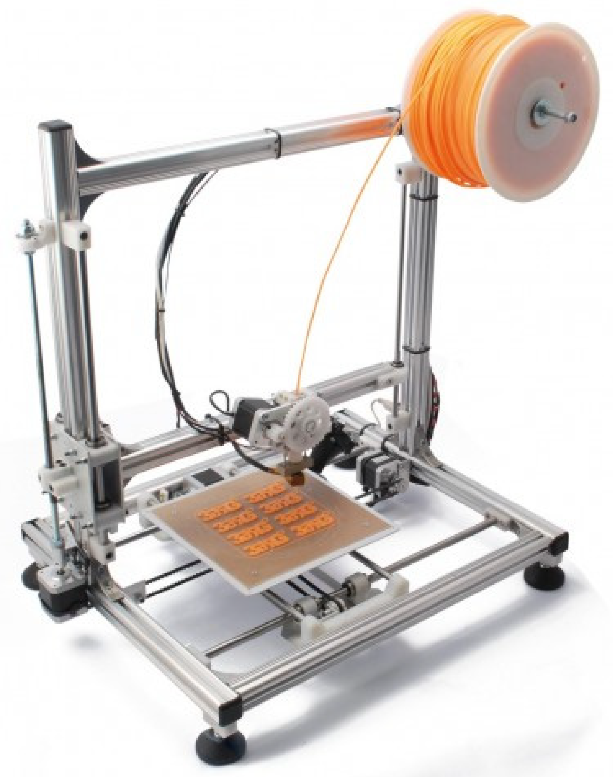
3DRAG—Cartesian: Cartesian printer is the most common design found in 3D-printing. It consists of a mobile printing plane on the horizontal axes
X and
Y, while the vertical axis
Z is dedicated to the cart, as can be seen in
Figure 1. This configuration makes the system of extrusion so much easier ore simple: the nozzle doesn’t move on the horizontal axis and it’s simply fixed to the structure that moves on the z axis. The 3DRAG printer can print objects with a maximum size of 20 × 20 × 20 cm. The measurements have been studied to give the printer a compactness and a low center of gravity. The support for the printing plate is designed to accommodate a heated plate which favors the correct cooling and the good adhesion of the printing material, reducing the risk of objects detaching.
The type of extruder used by the 3DRAG printer is the Direct Extruder, in which the hot part that melts and deposits the material—the hot-end—and the device that pushes the filament into the melting zone—the cold-end—are directly connected.
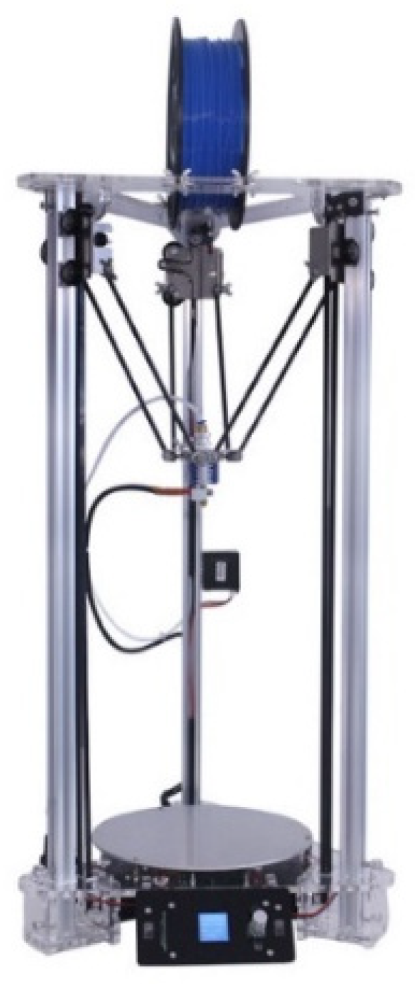
EZT3D—Delta
Another style of 3D-printers is the Delta one, more sophisticated than the Cartesian model. As shown in
Figure 2, it consists of three mechanical arms joined together at one end in which the extruder device is placed. The entire triangular-shaped prism structure (thus the name “Delta”) allows the extruder to work directly on the circular print bed. The movement of the three rods, each of which is controlled by a single electric motor, is designed to let the extruder reach every point in the space. The EZT3D printer uses the Bowden Extruder, where the motor is delocalized from the hot-end, separated by a Teflon tube, and is in a non-moving area of the printer.
Compared to the Cartesian printer, the Delta model:
- -
Can print longer objects, thanks to its height development, for maximum dimensions of 18 cm in diameter and 32 cm in height.
- -
The Bowden system reduces weight on the cart. The moving parts are light, there are fewer masses to stop: that means a faster and more accurate printing, unlike most of the traditional printers that have the bed surface in motion.
- -
The level of accuracy is the same, but with the same parameters (such as layer height, print speed) it guarantees a better surface finish, because it is free from vibrations that affect the Cartesian bed surface.
- -
It is more complicated to calibrate and requires notably higher number of calculations to work.
3.2.2. Types of Materials
A material suitable for FDM 3D-printing must be thermoplastic, which becomes soft and moldable when heated and returns to the solid state when cooled. The two dominant plastics for 3D-printing nowadays are PLA and ABS.
PLA: Created from the processing of various plant products, including corn, potatoes or sugar beets, PLA—Polylactic Acid—is a biodegradable plastic and therefore more “environmentally friendly” compared to ABS, based instead on oil.
It is naturally transparent and can be colored with varying degrees of translucency and opacity. Printed objects typically have a sleeker appearance than ABS.
The melting temperature of PLA is quite low and the 3D-printing process takes place at temperatures of around 180–185 °C. During the extrusion a sugary and non-toxic smell is produced. When cooled quickly, it can achieve better surface finish, faster printing speeds, lower thickness layers and crisper printed corners.
ABS: Acrylonitrile-Butadiene-Styrene (ABS) is a synthetic thermoplastic, derived from petroleum. As a polymer it can have many forms and many properties. In general, it is a plastic with better strength, flexibility and workability than PLA. Its flexibility enables the creation of interlocking pieces that are easier to work with (LEGO bricks, for example, are made of ABS). Compared to PLA, ABS is much easier to recycle.
The extrusion temperature can vary between 220 and 260 °C. ABS printing often causes a noticeable smell of heated plastic, so it’s necessary to ensure proper ventilation in the room of use. Unlike PLA, it guarantees better final characteristics in the printed object if the cooling takes place slowly.
ABS models molded are much more resistant than those in PLA, but neither of the two types is optimally resistant to an autoclave sterilization treatment.
HT-PLA: High Temperature PLA (HT-PLA) is printed like PLA, but it can be heat treated to withstand high temperatures. It is printed at 190–200 °C and after the heat treatment can resist up to 145 °C, a higher temperature than that tolerated by PLA, ABS or polyesters that lose their structure at 60 °C.
The treatment consists of baking: the molded parts are placed in an oven until there is a change from translucent to opaque. It takes 5–10 min for small and thin parts and few hours for large ones. The pieces molded in HT-PLA crystallize in an oven at 110 °C and improve their mechanical characteristics: they increase surface hardness, stiffness and strength but, above all, the thermal resistance, which makes this material suitable for autoclave treatment for possible sterilization [
4].
4. Methods
CT scans do not depict three-dimensional surfaces, but only 2D images of the body sections in the three planes of space. 3D-reconstruction and 3D-printing are methodologies that allow us to effectively visualize and handle, in person, the reproduction of the object under examination in full scale, during the preoperative phase, without limiting itself to the observation of images acquired with CT scans.
Thanks to this three-dimensional reconstruction, it is therefore possible to observe the anatomical region in the CAD viewer and interact with it, not only roto-translating it in the 3D space, but also highlighting possible fractures or lesions and applying simulations to observe the result of a possible surgical procedure.
The ultimate purpose of the method is represented by the 3D-printing process. The outcome of the printing is a three-dimensional object that perfectly reproduces the anatomical part subject of the CT scan and is intended for surgery. Once printed, the surgeon can then observe the biological structure of interest not only to the virtual viewer, but also live, and similarly can perform measurements, apply cutting masks and compare with other doctors and with the patient himself for a correct surgery, improving that procedure compared to the traditional method.
The method is complex and requires an interdisciplinary approach between different kind of skills, which can be localized within the same hospital or in external centers, as in the cooperation between the Department of Industrial Engineering of the University of Bologna (DIN) and the Rizzoli Orthopedic Institute (IOR), as concerns activities such as the study of biomechanical movements, the production of customized orthotics developed following the 3D scan of the foot, the creation of orthopedic cutting masks, and three-dimensional models deriving from CT scans of the bone.
This collaboration exploits the teamwork created between doctors and engineers during the preoperative briefing phase in the orthopedic field.
For medical applications, images are acquired by CT scans or MRI. The X-ray data set is in the DICOM file format. The first step in the generation of a three-dimensional anatomical model is the extraction of the target geometry from the medical images imported in the DICOM format. This image segmentation process divides an area of the radiograph into non-overlapping regions, connected, coherent and homogeneous. The primary aim is to reduce the complexity of the original image, leaving a comprehensive representation of the relevant characteristics. The level of image partitioning depends on the complexity of the problem being faced [
1].
Segmentation procedures can be divided into the following categories:
- (a)
manual, where the outlines of the selected image portion are manually adjusted on the display.
- (b)
automatic, in which the algorithm automatically divides the image into predefined regions that show similar characteristics within these areas and differ from one region to another.
Modern CT scanning equipment is capable of providing up to several hundred images for each phase, so a manual approach is hardly compatible with the images to be processed and this would be not so accurate. Automatic segmentation systems have been developed for different anatomical parts such as bone, skin, muscle tissue and fat tissue. These structures are characterized by a greater homogeneity in the imaging results, but the algorithm is based on several predefined hypotheses that may not guarantee the generation of an optimal volume.
Once the anatomical region to be extracted has been selected, the 3D surface is created. The format used to export the created volume is the STL file (Standard Triangulation Language). An STL file concerns the geometric representation of the object through a mesh (for example, a series of oriented triangles). The greater the number of triangles oriented, the better the surface quality of the object. According to the specific clinical case, it may be necessary to perform further post-processing on the final 3D-model, such as surface leveling, ensuring that the clinical information would not be compromised during this process.
The second step of the methodology concerns the optimization of the three-dimensional surface. The STL format we have extracted was already suitable for the 3D-printing approach, but its characteristics were still not appropriate: the volume extracted with the segmentation was definitely irregular, both from the aesthetic point (holes, self-intersecting surfaces and flipped or duplicate triangles), and also from a functional point of view (too many triangles that leads to a too large file).
Some powerful tools can help repair models, by reducing the number of triangles of the mesh. First of all, we start by eliminating “orphaned” triangles situated in the model’s internal cavity and they are unattached to the rest of the object and so they are useless. This procedure makes the file more streamlined, with less complicated geometry and therefore occupying less memory.
Later, the 3D reconstruction continues with the mesh repair, by filling all the missing triangles that creates holes in the surface. A “non-manifold elements” tool can look through the model and highlight problematic edges to visualize the holes which will be filled with the right command. Subsequently, rendering is required to improve the quality of the mesh, such as the manual fixing of tiny overlapped triangles or the surface smoothing, which can be automatic or manual, and global or focused on groups of mesh entities.
After completing these operations, the created mesh can be considered optimized, of good quality and therefore ready for the 3D-printing phase approach.
5. Case of Study
5.1. Generation of the 3D Surface
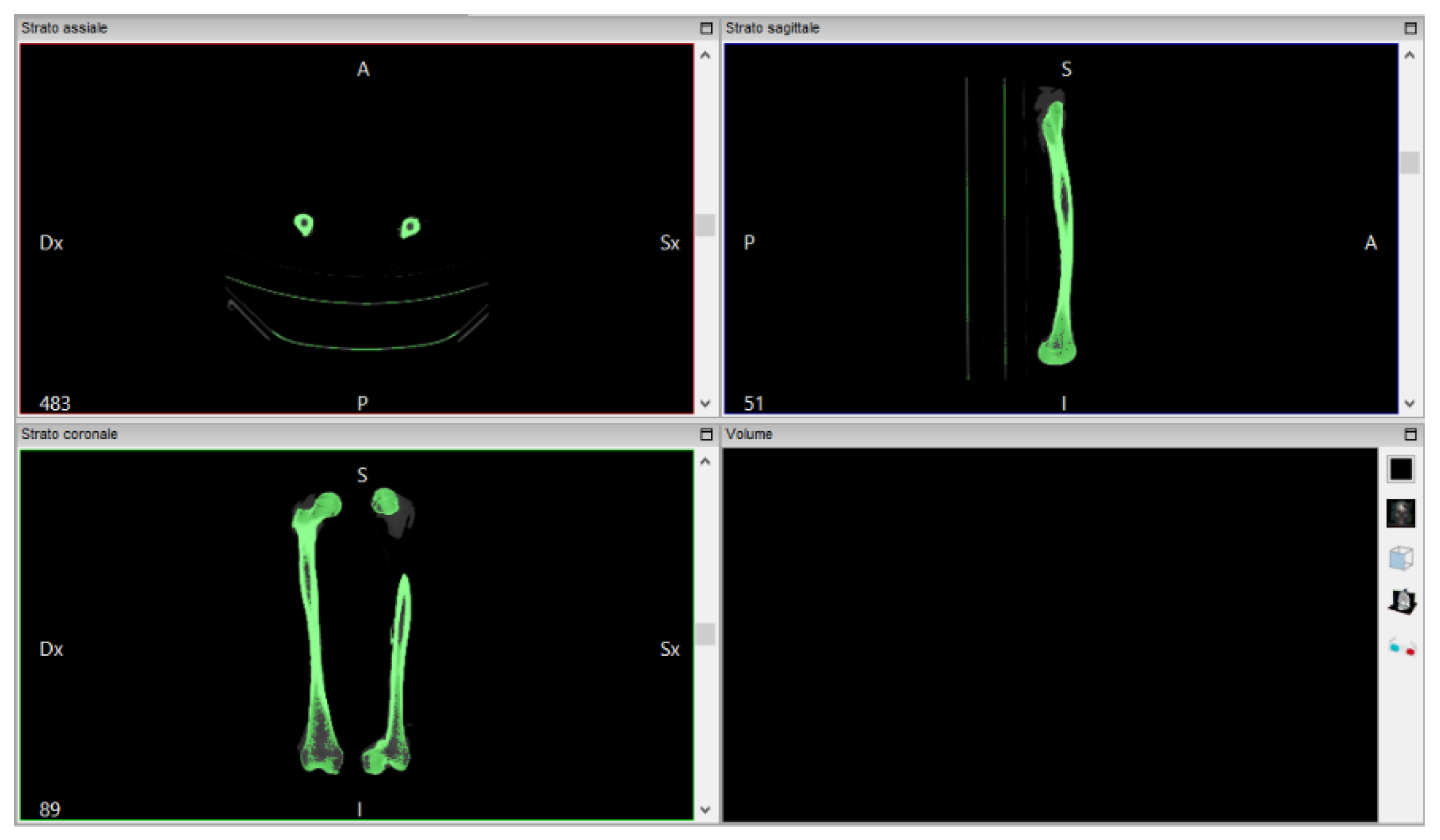
The software “InVesalius”, with the input data of a femur CT scan, generates the 3D surface of the anatomical part. The file is imported in DICOM format. The analyzed work involves a thigh CT scan, from which just the bone is extracted (
Figure 3).
InVesalius shows the views on the three floors of the region subjected to the CT scan:
The next step is to convert the CT scan into a three-dimensional mathematical representation. The quality of the reconstruction will depend on the number of layers contained in the medical examination and the selected range: to create the 3D surface you must select in the program a threshold that can be automatic (compact bone, spongy bone, skin, muscle tissue) or manual, so as to extract only the object for which you want to create the 3D surface, highlighted in green.
Proceed by selecting “Compact bone (adult)” to create the three-dimensional surface of the two x-rayed hips. The volume of the selected region is displayed on the screen in the lower right window of
Figure 4.
Once created, the 3D surface was exported in STL format. InVesalius provides the three-dimensional surface, in STL format, of the bone from which the tomographic image was imported in DICOM format. The new created mesh results coarse and non-homogeneous.
5.2. Mesh Repairing
The file extracted from InVesalius was a mesh characterized by irregular shapes and various overlapping layers that make it a very heavy file. For this reason, during this phase of the methodology, a 3D surface cleaning was performed, using a software for the management and editing of geometric structures, MeshLab.
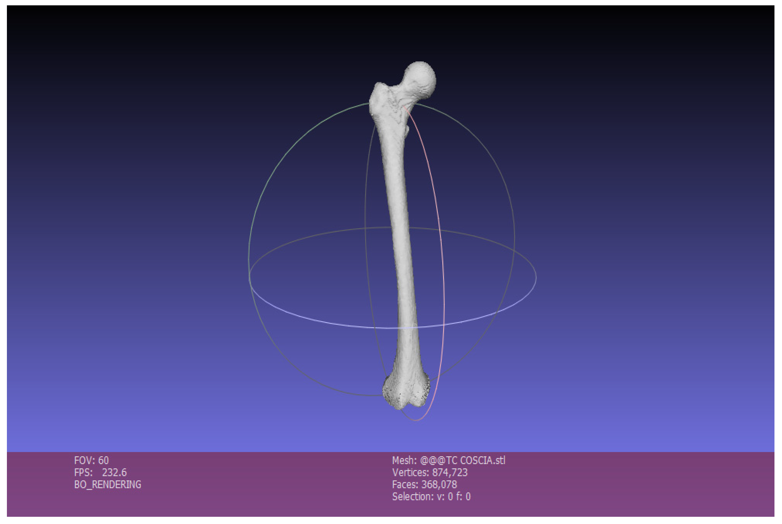
The work now proceeded with the consideration of the right femur alone, for reasons of simplicity.
Once the STL mesh had been imported into the MeshLab software, we could view indications on the number of vertices and faces, as you can see in
Figure 5.
We can point out how, particularly near the ends of the bone, there are holes, cavities, ripples and general irregularities to be corrected in order to print an object correctly both from a functional and aesthetic point of view.
There are three main steps to repair the mesh with MeshLab:
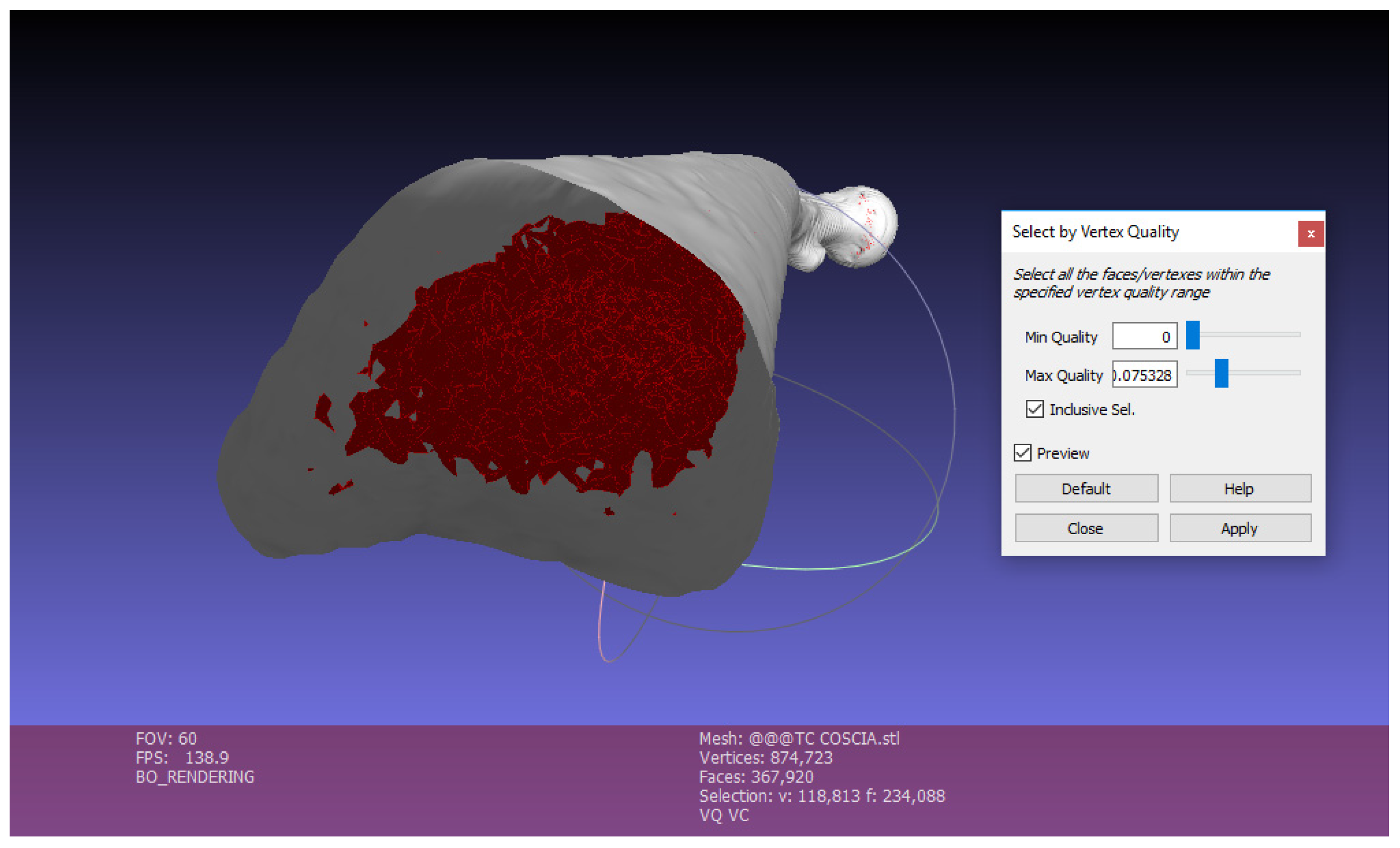
Exterior surface lighting: The first operation to do with this software is the “Ambient Occlusion” (command: Filters, Color Creation, Ambient Occlusion, Per Vertex). This function simulates a diffused global illumination by throwing rays from every visible point and calculating how many of these actually reach the “sky”—considered as a light source—and those who are obstructed.
With this function the object is illuminated externally, while vertices and faces contained inside the mesh are obscured, so that they can be easily selected and eliminated to reduce the complexity of the mesh, as shown in the following point (
Figure 6).
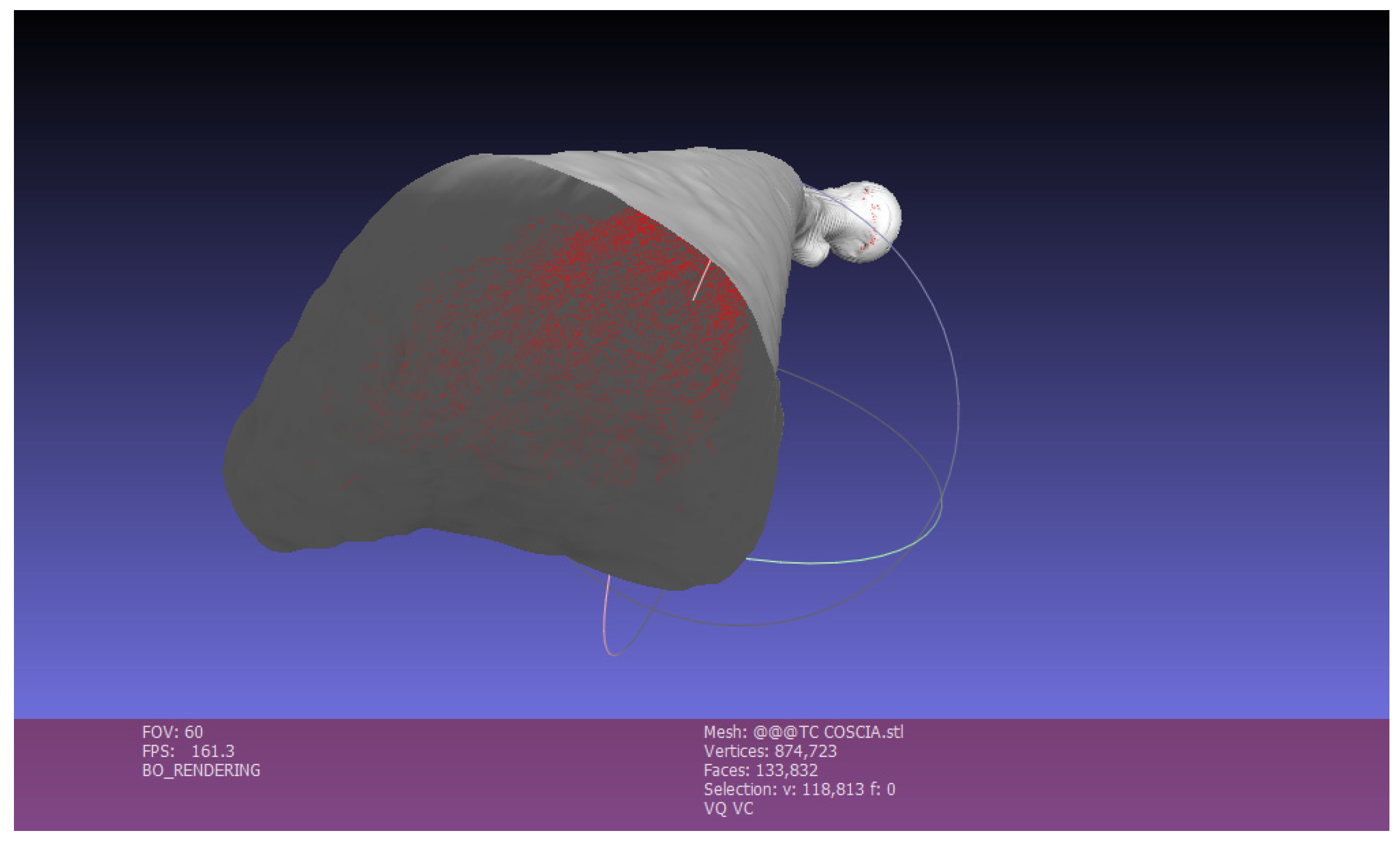
Once selected, by clicking on Apply, Close and then Delete, the faces highlighted in red will be deleted. In this way the several faces contained in the mesh are strongly reduced. The mesh becomes much lighter (
Figure 7).
Elimination of Small Components
This function is used to eliminate small isolated surfaces that are separated from the created 3D bone surface. In the appropriate command you choose the Ratio, that is the quantity in % below which the components are eliminated: Filters, Select, Small Components, Ratio 0.1.
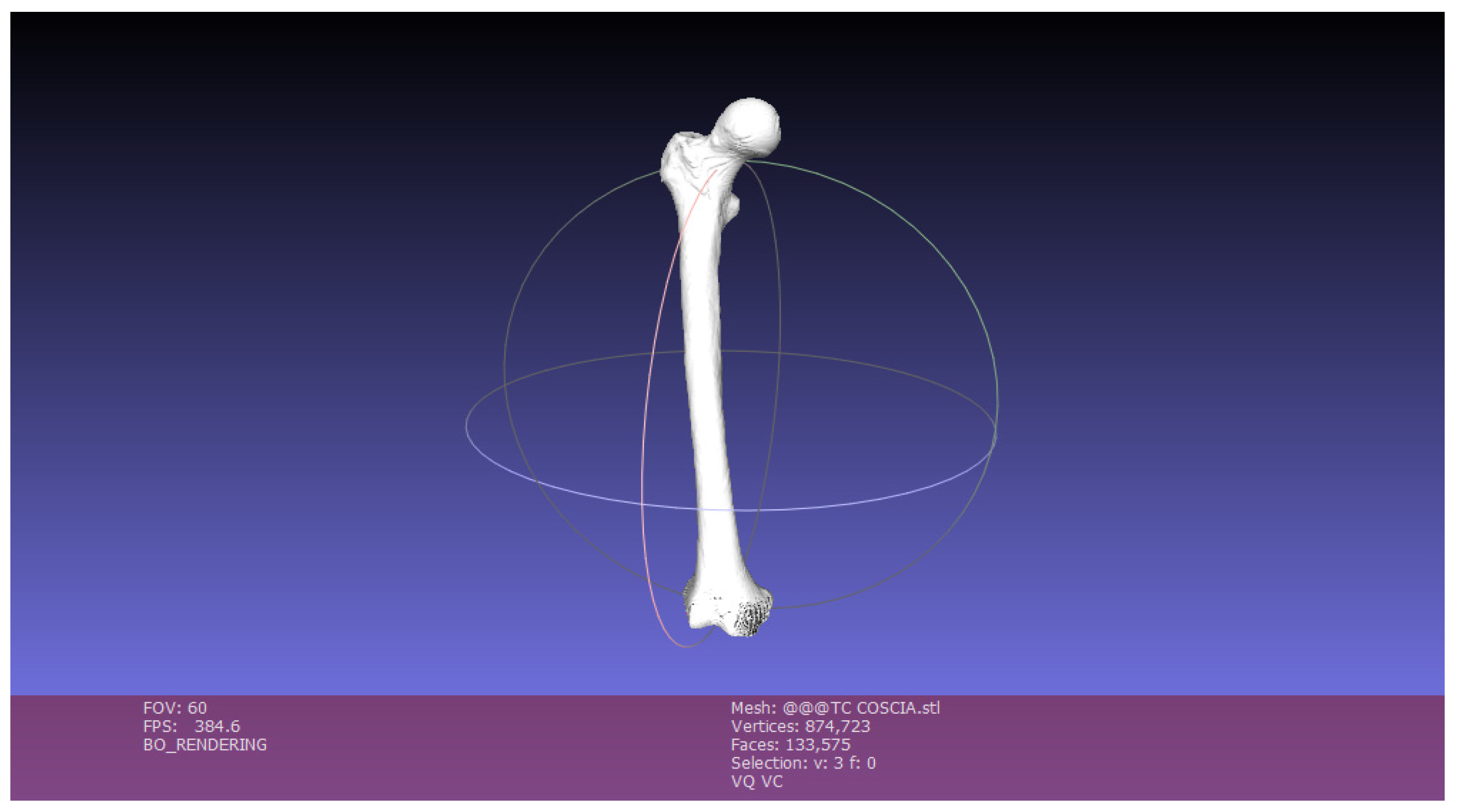
It is clear from
Figure 8 the output generated by the operations performed on MeshLab:
When the operations are finished, the mesh is exported.
The object that is obtained after the operations in MeshLab is a three-dimensional surface in STL format that has been cleaned up and lightened. It is possible to notice the “faces” data, which identifies the number of faces of which the 3D surface is made: the imported mesh has 368,078 faces, while the exported model, cleaned up and repaired, has 133,575.
5.3. Mesh Optimizing
The mesh exported with MeshLab contains a three-dimensional model cleaned up and streamlined but is not yet ready for 3D printing. It is necessary to perform a phase of optimization of the 3D object: it is then imported onto a new graphic software, Blender, with the aim of repairing the mesh, removing faces of zero area, faces with normal incongruities, overlapping faces and “non-manifold” edges.
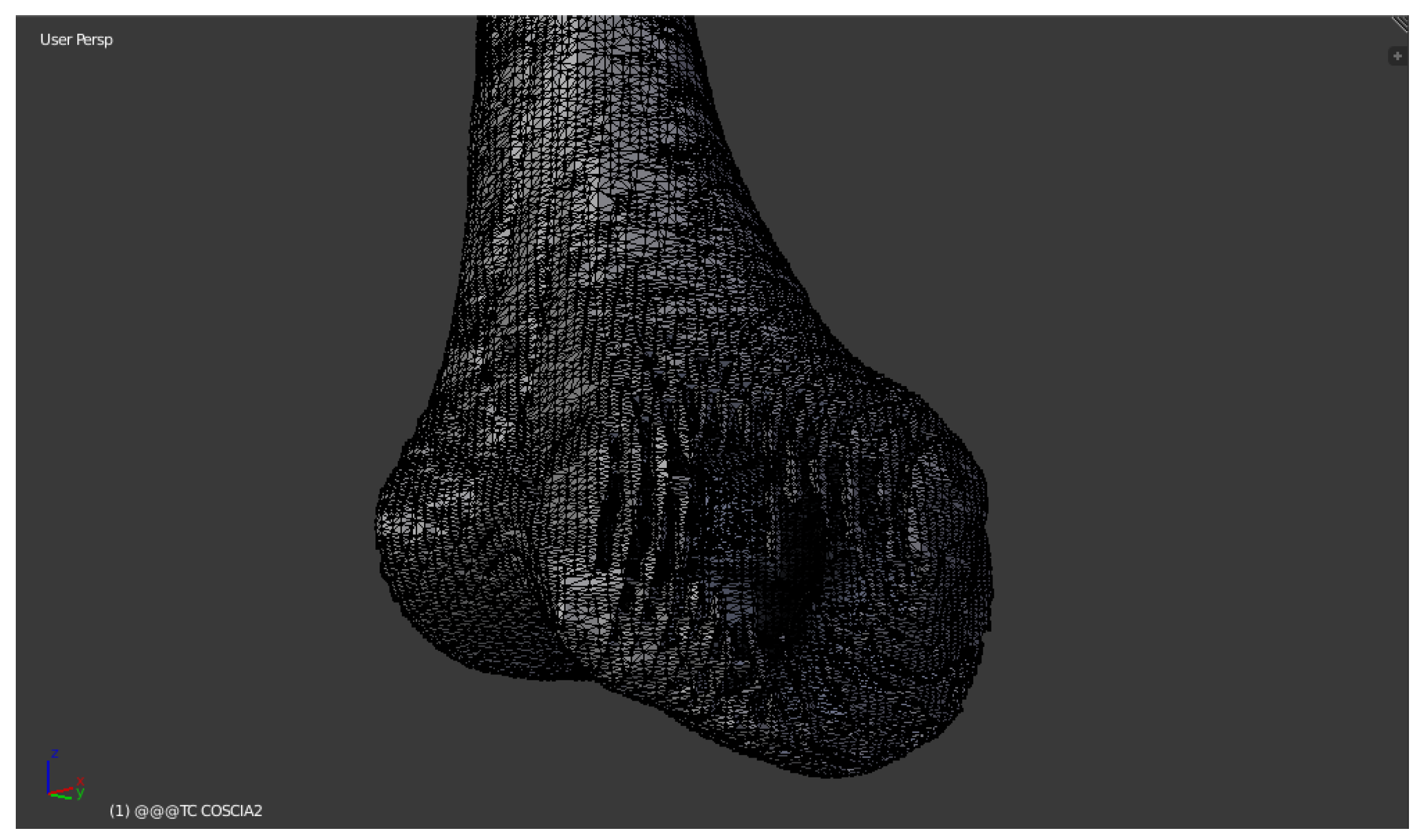
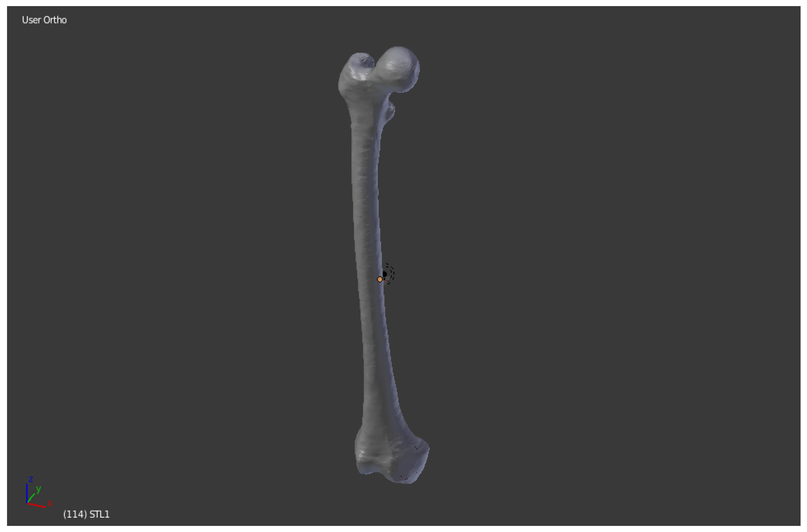
Figure 9 shows the Blender display window:
The cleaned femur was imported to Blender. The mesh is now slimmer than the one generated with InVesalius, but it is possible to figure out the presence of holes, cavities and imperfections especially in the lower part of the anatomical structure.
Going through the Edit Mode interface, this software allows you to perform all the repair and optimization of the mesh to make it suitable for the 3D printing process.
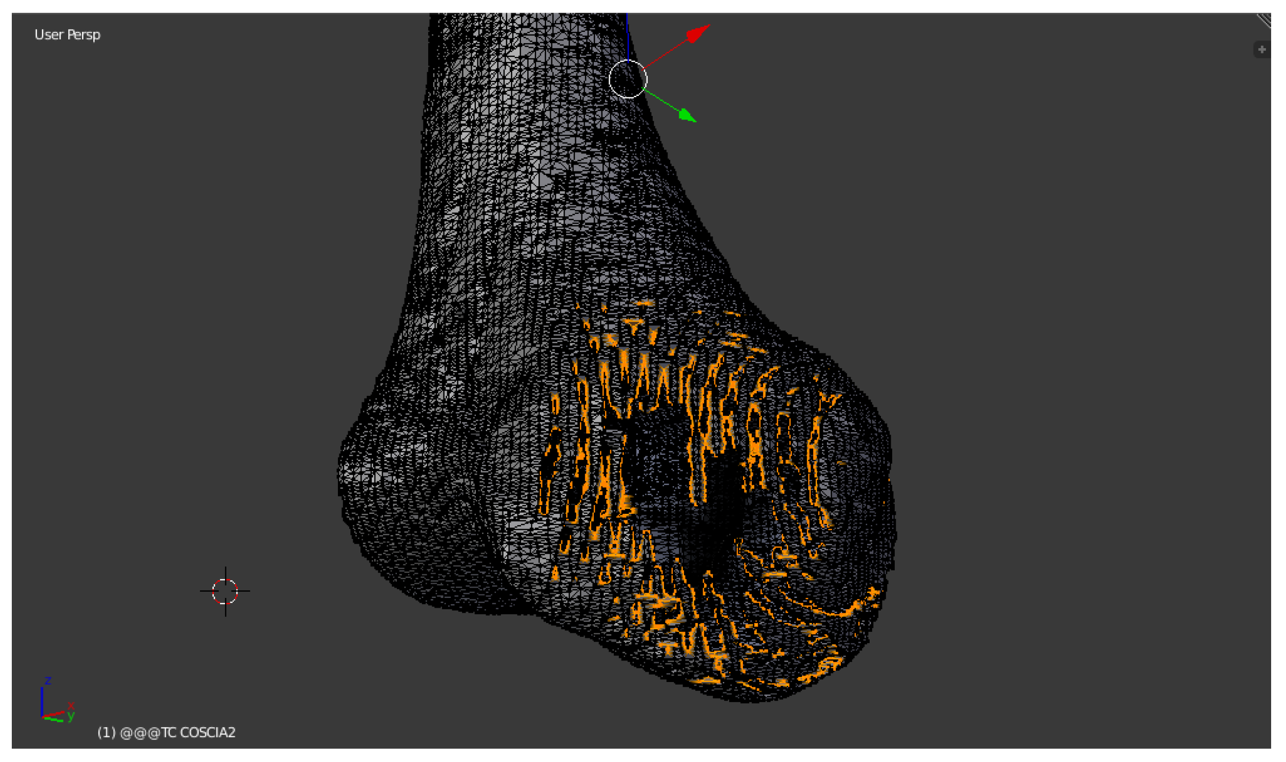
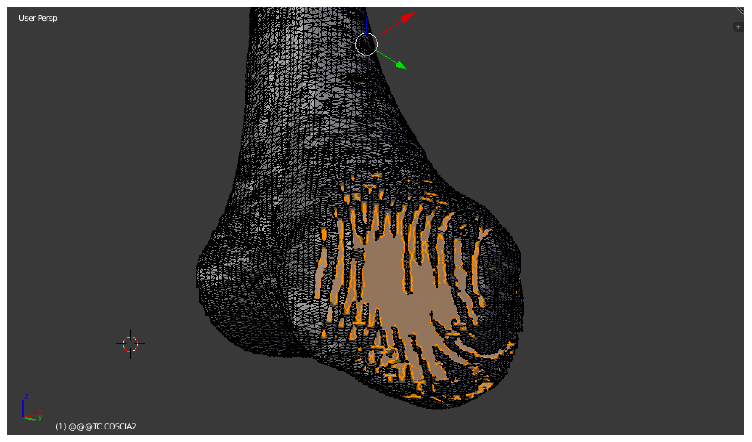
Firstly, all the holes on the surface are closed (
Figure 10,
Figure 11 and
Figure 12). As in most of the functions that can be performed by this software, a keyboard command is used: CTRL + SHIFT + ALT + M, which allows to select all the “Non-Manifold” components, i.e., the disconnected edges and vertices or non-area faces, and subsequently with the command F—Fill—to proceed to the filling [
5,
6,
7].
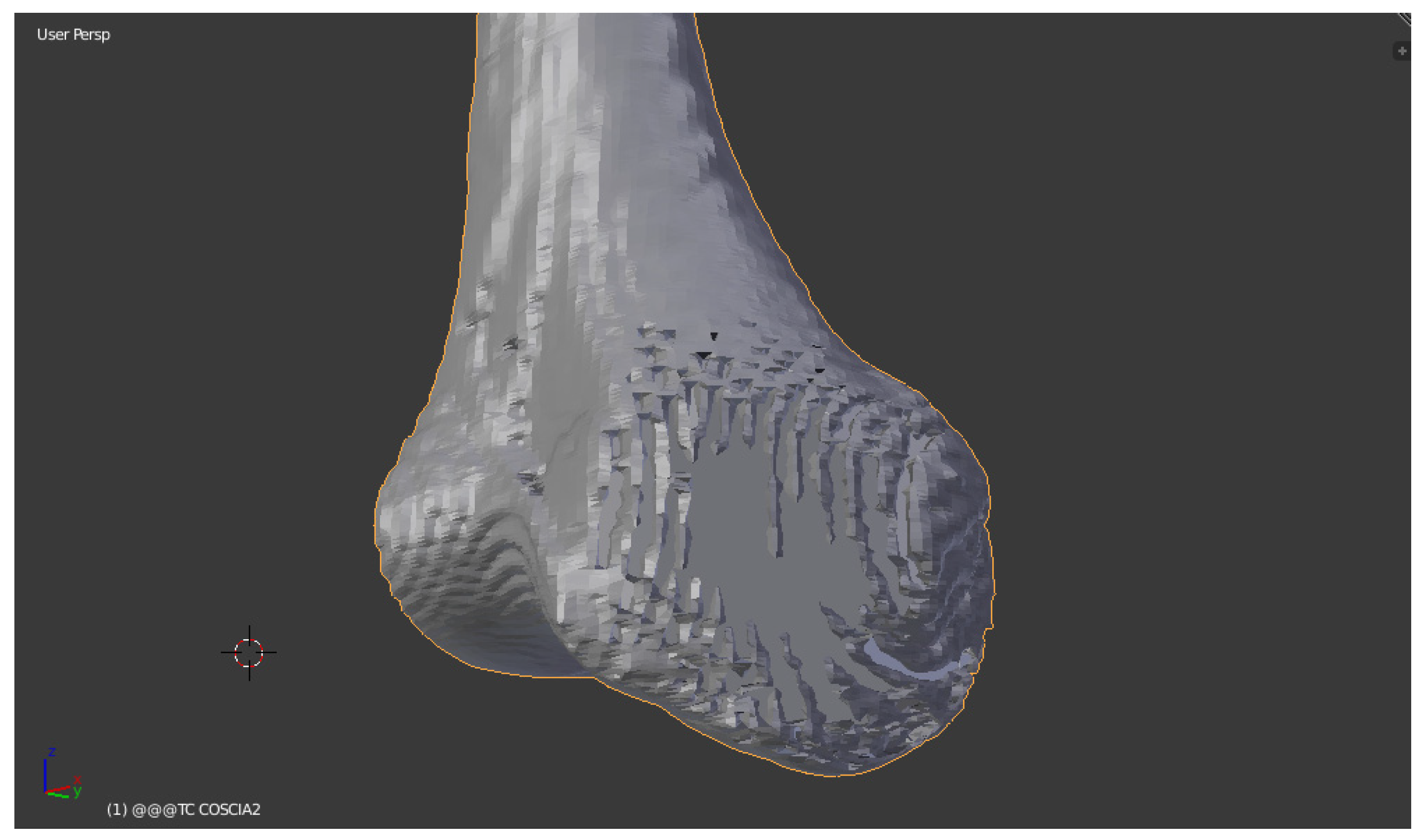
In the Object Mode it is possible to observe in
Figure 13 how the 3D model is completely devoid of holes, but from the aesthetic point of view it appears rough and with notable inaccuracies:
To solve this problem, use the Smooth function.
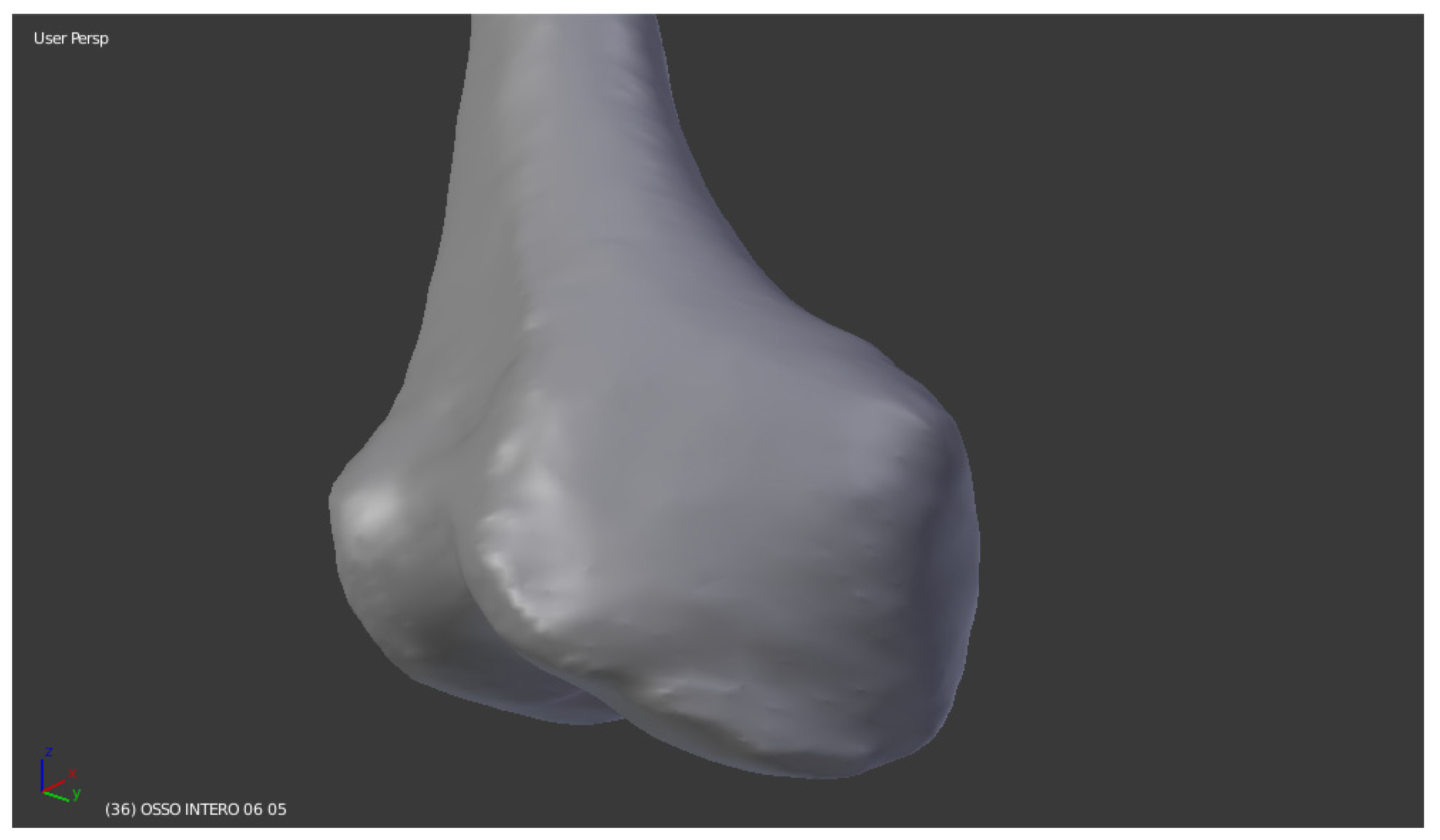
Polygons play a central role for Blender. All objects are represented by generating polygons and the curvatures are approximated by polygon meshes. During rendering you can see their presence as a series of small flat faces. Sometimes the effect is desirable, but you prefer three-dimensional objects that are cute, slick and smooth.
In the case of study, the surface sanding was done manually thanks to the Sculpt Mode interface: instead of dealing with single elements (vertices, edges and faces), the desired area of the model was altered using a brush. From the Sculpt Mode you select the brush—manually—to make the entire surface of the three-dimensional model smooth (
Figure 14).
Once smoothed, the last step necessary before the launch of 3D printing is the segmentation of the bone into several portions, to allow printing in compliance with the maximum extrusion dimensions of the EZT3D printer (max 320 mm in height) present in the Department of Industrial Engineering (DIN).
The considered femur has a dimension Z = 463mm. This is supposed to divide it into three bone segments to adapt it to the 3D printer. Following the partition of the mesh, the appropriate pins were created to allow the mechanical connection by interference of the three portions, which were printed separately.
First of all, we defined the references for the correct division of the bone into three parts. We selected the bone mesh with the right mouse button, then with CTRL + SHIFT + ALT + C command and click on Geometry to Origin the origin is fixed on the center of the bone (
Figure 15).
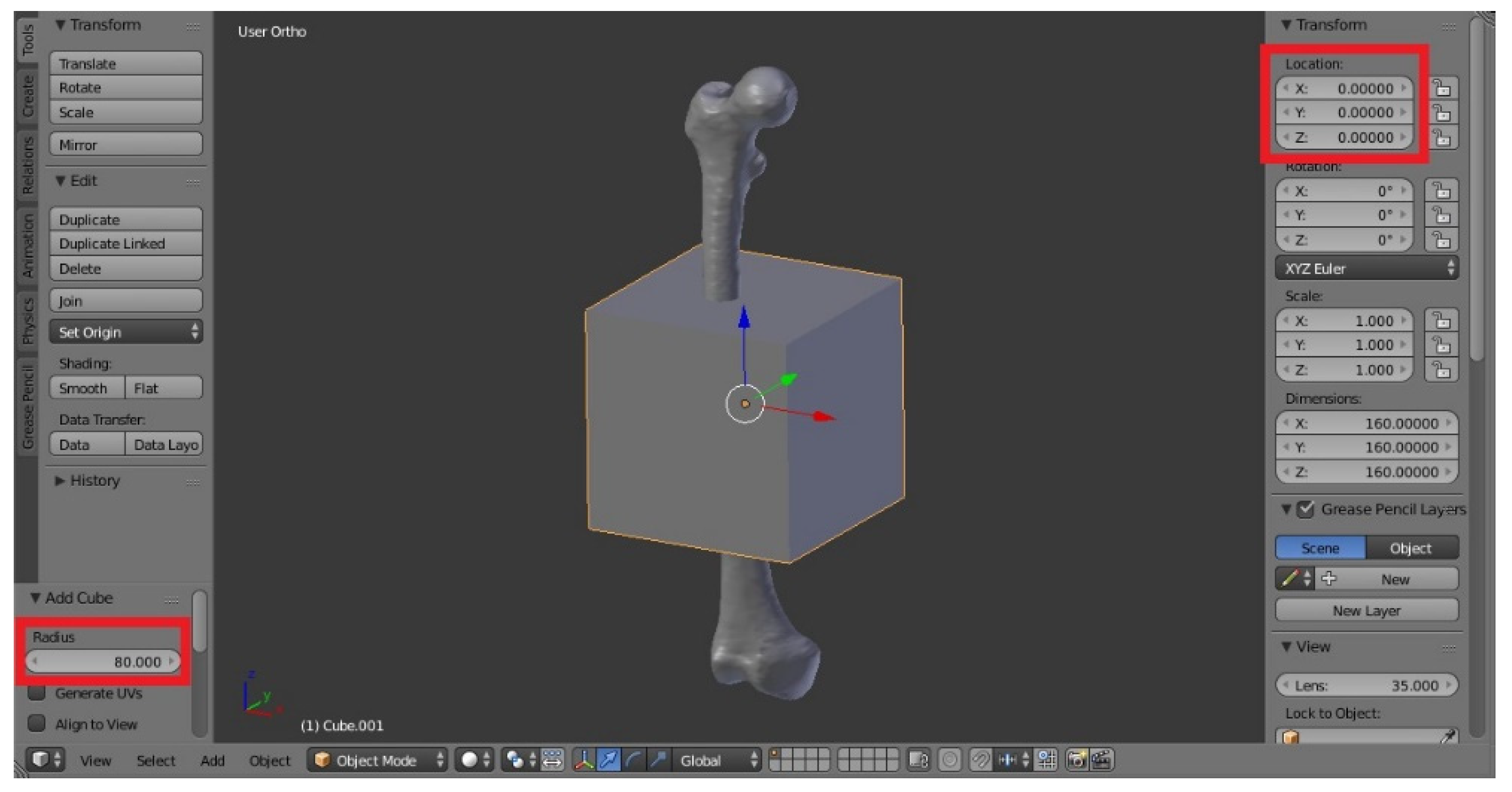
Then a cube was added, with the Add, Mesh, Cube function. We defined Radius = 80, in order to add, in the visualization, the predefined mesh of a cube of dimension 160 × 160 × 160 mm. The cube was placed randomly. In order to have the center corresponding to the origin and therefore to the center of the bone, select the cube and with the N key define Location (0, 0, 0). A cube is obtained that penetrates the bone. The three segments in which the bone will be divided will be the two outgoing ends, corresponding roughly to the “epiphysis” in the long bones, plus the central part covered by the cube, which is instead the “diaphysis” (
Figure 16).
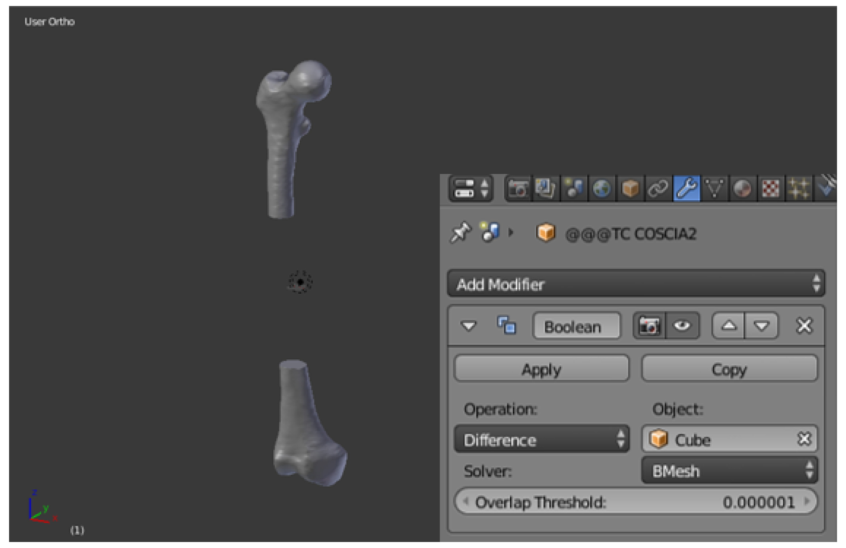
The real division of the mesh into several parts was obtained with the Boolean function. To create the two ends, select the bone and from the Modifiers (wrench icon) command in the right menu select Boolean: use the Difference operation with report object the cube created before.
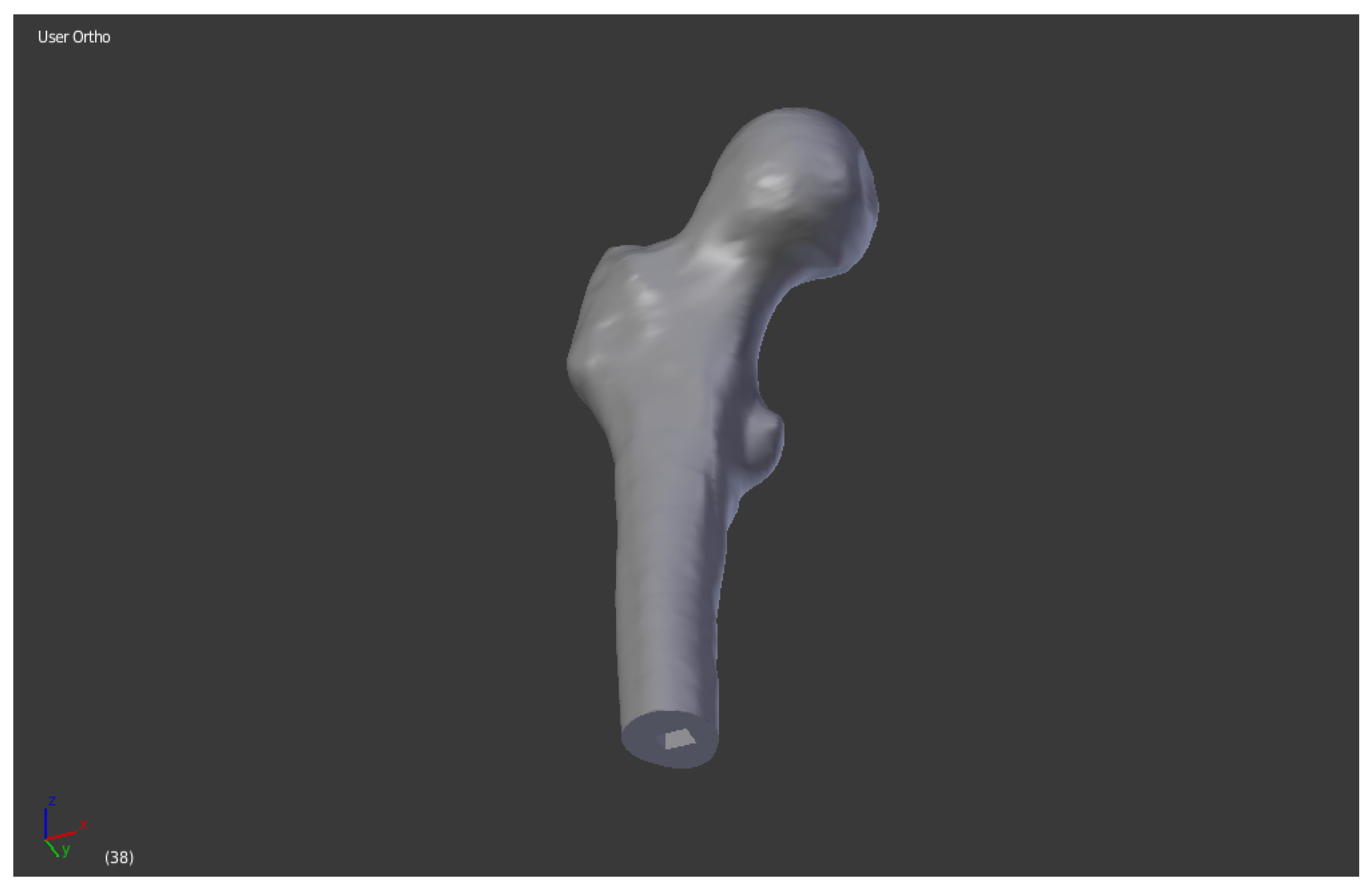
Simply click on Apply to create the difference between the two solids. By deleting the cube there were then the two separate ends, as the difference between the two meshes. We proceeded to save separately the two portions as STL (
Figure 17).
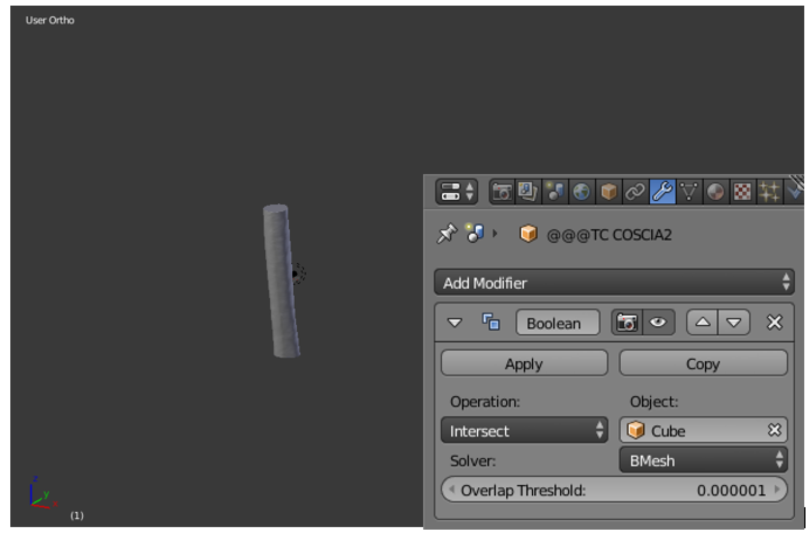
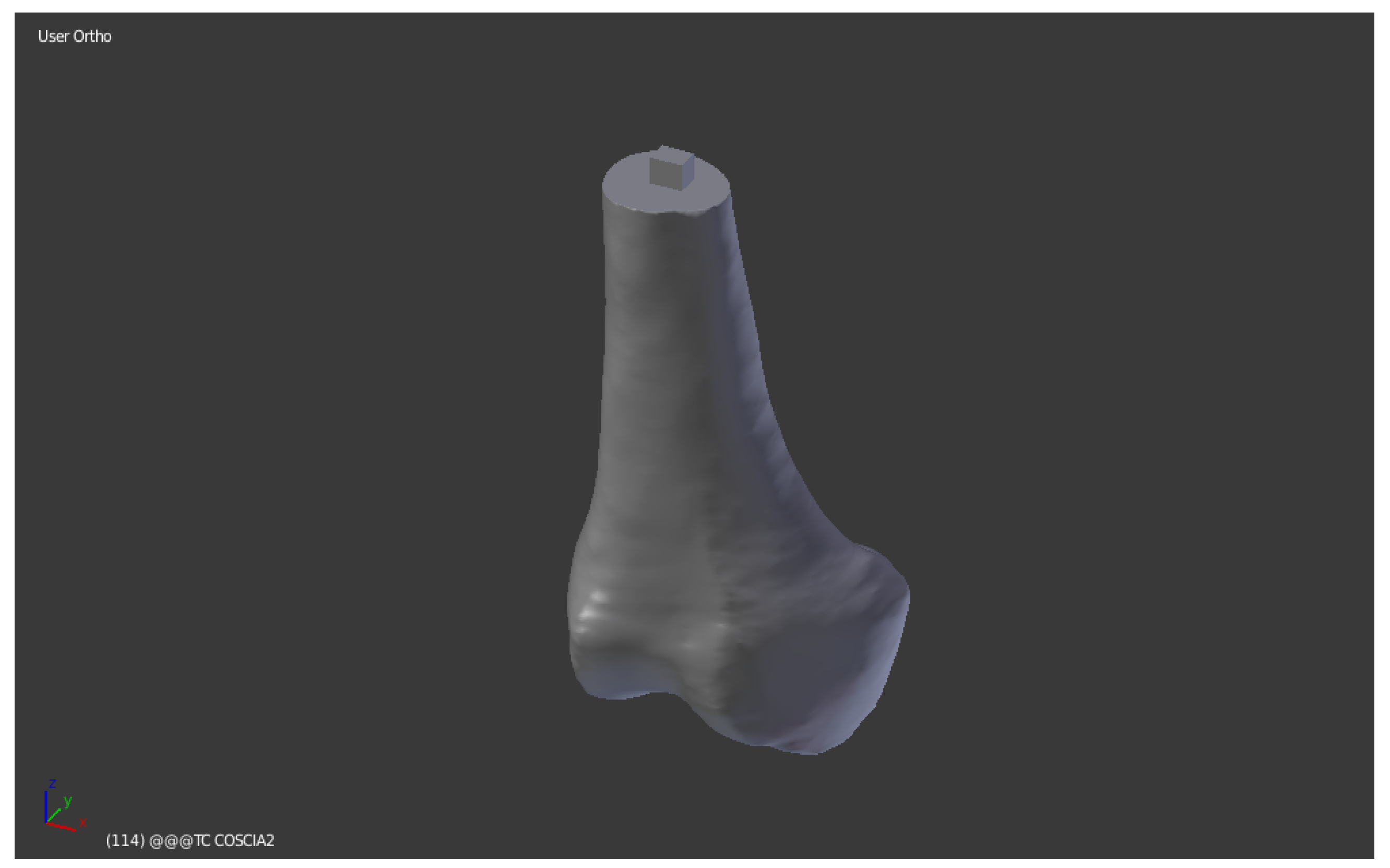
To get the central part, reopen the file in BLEND format of the whole bone and repeat Steps 1 and 2. At this point the Boolean between bone and cube is applied again with the Intersect command. This function only leaves the central part of the bone in the viewer, the one that was covered by the cube in the second step. Then delete the cube and save the STL mesh (
Figure 18).
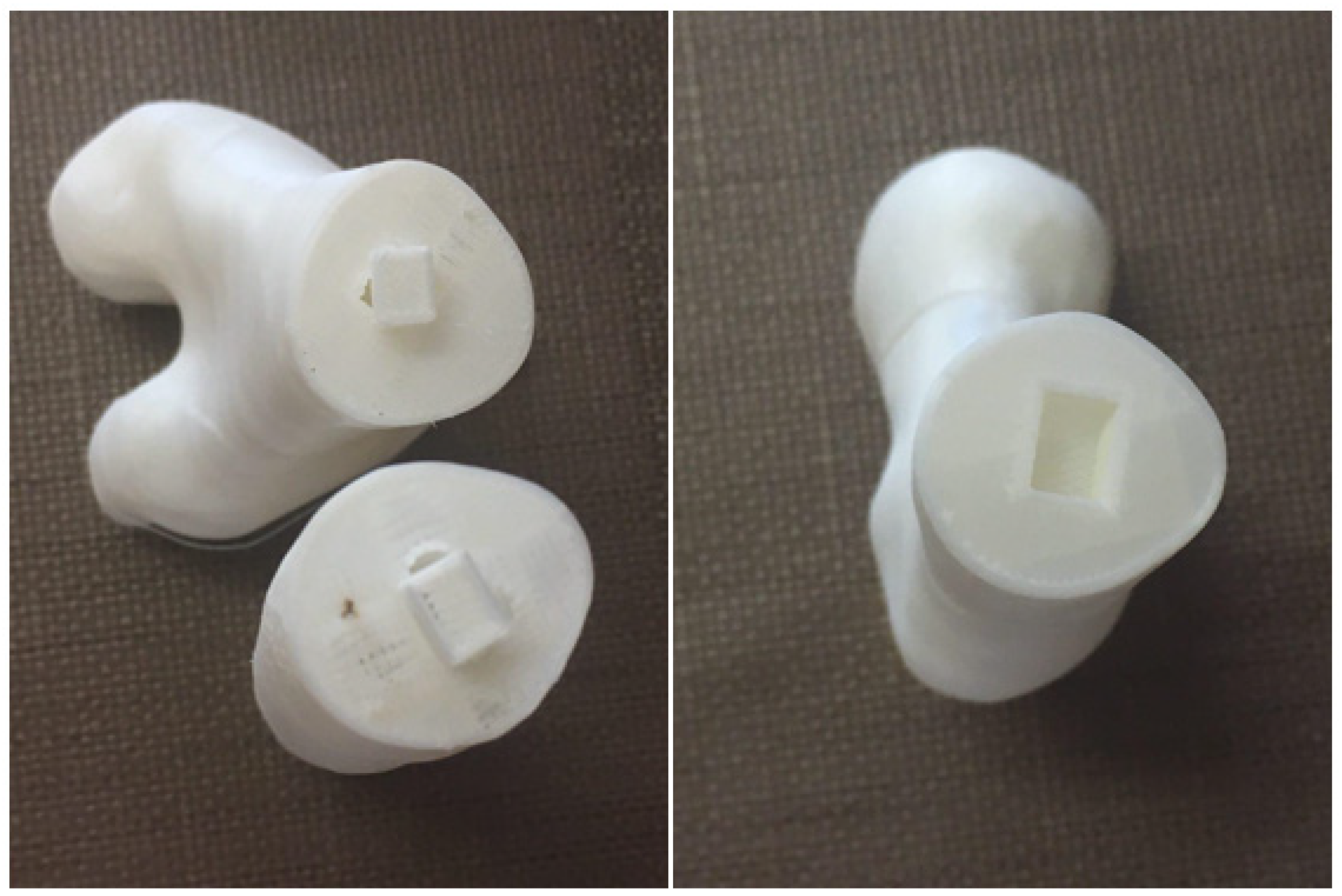
Once the bone has been divided into the three anatomical parts to be adapted to the dimensions of the print, it is necessary to create the shape connection to fix the different pieces once extruded by the 3D printer. It is supposed to create rectangular pins. This step is also possible with the Blender software, operating individually on the three bone segments.
We refer to the central part of the mesh, the diaphysis, which is equipped with both the male part—above—and the female part—below—of the connection.
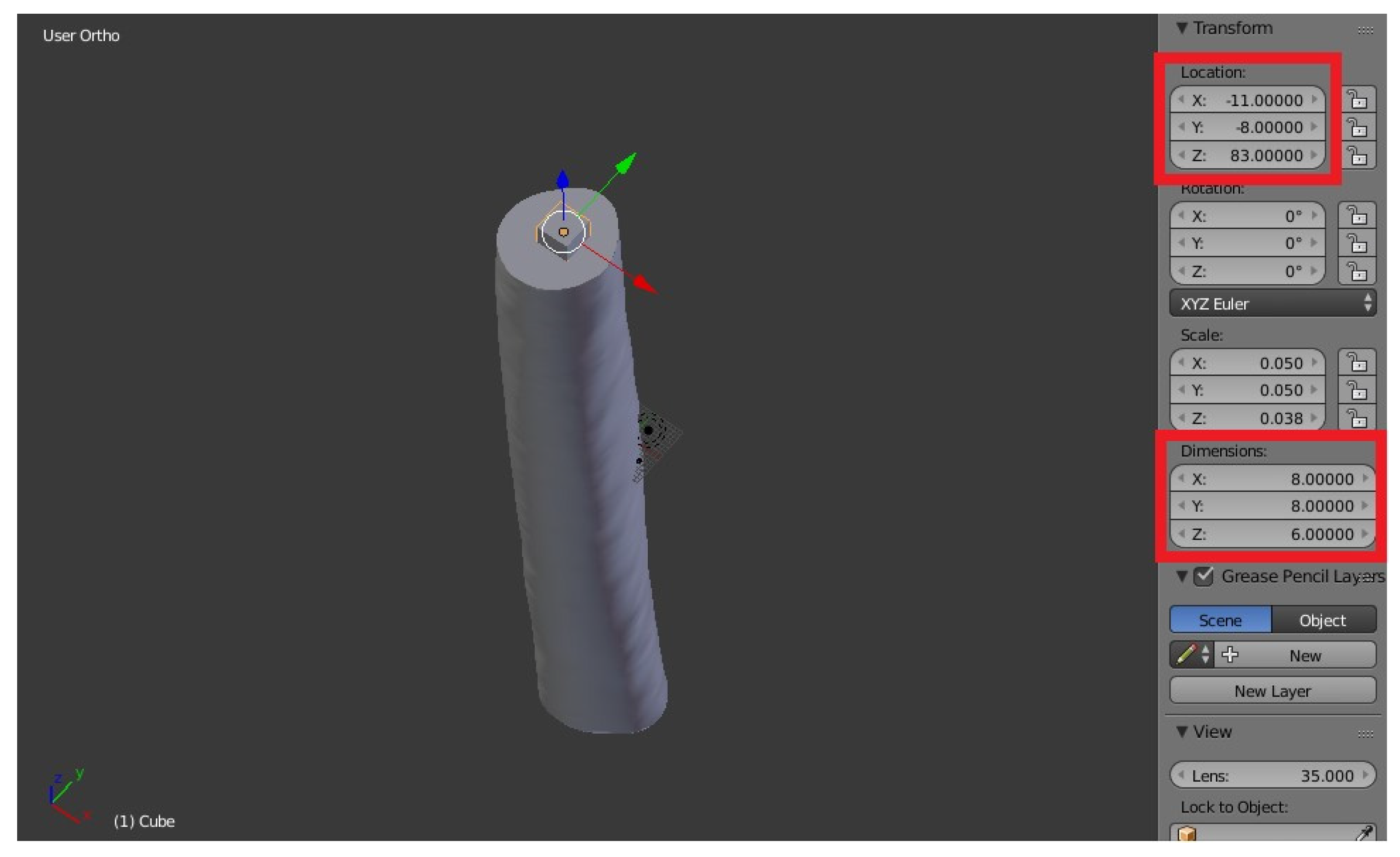
Male component: To create the pin, add the default mesh of the cube, which must be resized, from the N key menu, to a rectangular shape with the following dimensions:
X = 8,
Y = 6,
Z = 6. Always use the N command, define Location (
X = −11,
Y = −8,
Z = 83): these are references taken manually to match the position of the spine in the central area of the upper horizontal plane formed on the considered mesh portion. It is important to define the position, because it will then have to correspond to the relative female component of the proximal epiphysis (
Figure 19).
The central bone segment and the newly created rectangle appear as two separate entities on the display. To join them you need to select the bone and use the Boolean function again with the Union command between bone and cube, thus creating a single body.
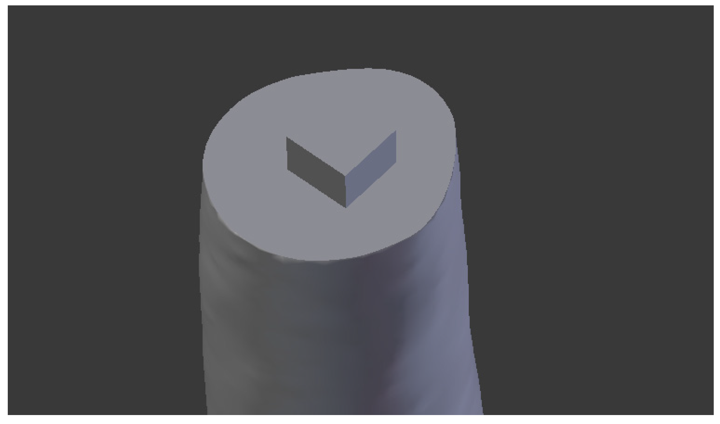
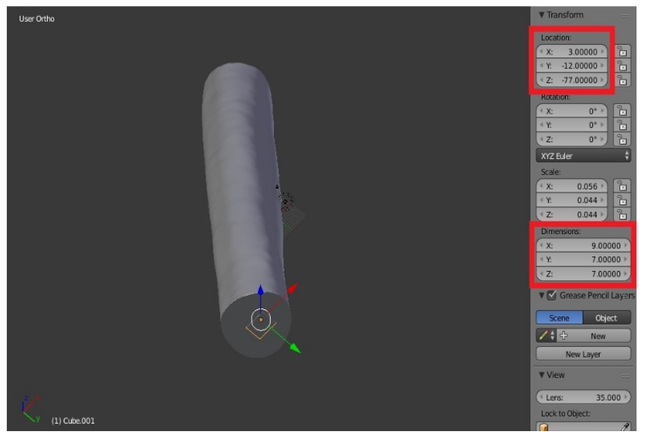
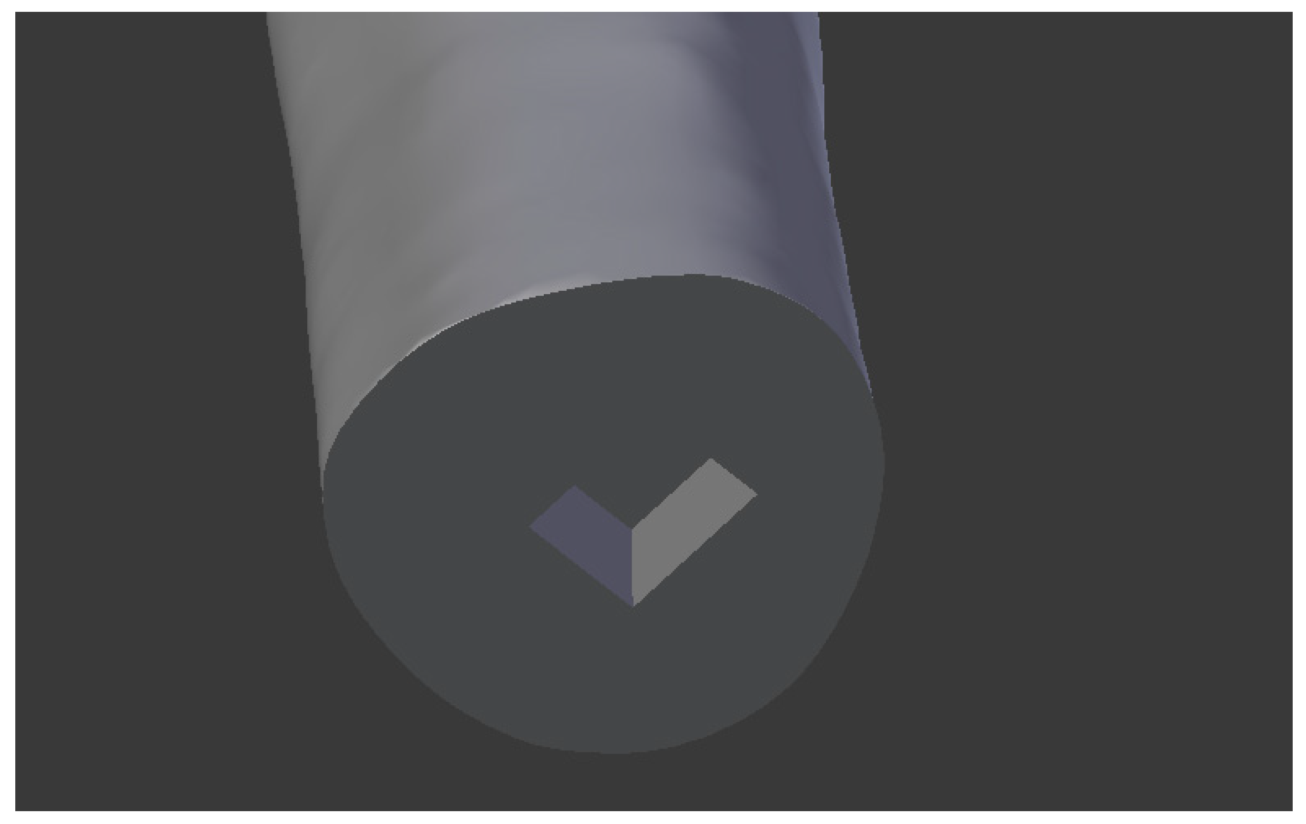
Female component: Similarly, add the Cube, then with the dimensions: X = 9, Y = 7, Z = 7. The size of the female was chosen deliberately superior to the male to allow the parts to be fixed with hot glue, once printed. Define Location: we take X = 3, Y = −12, Z = −77.
The parallelepiped is “inside” the bone in the viewer (
Figure 21). To create the female component, you must make the difference between the bone and cube mesh: select the bone, then the Boolean function with the Difference command, as already seen in third step of the division of the segmentation of the mesh.
As a result, the male part of the link was built on the lower segment, while the female was on the upper segment, both similar to what already seen [
8,
9,
10].
Proximal epiphysis: The pin was placed in the same location of the male of the central portion (
X = −11,
Y = −8,
Z = 83) (
Figure 23).
Distal epiphysis
In this bone portion the male part was built in the same position of the female of the central part: Location (
X = 3,
Y = −12,
Z = −77) (
Figure 24).
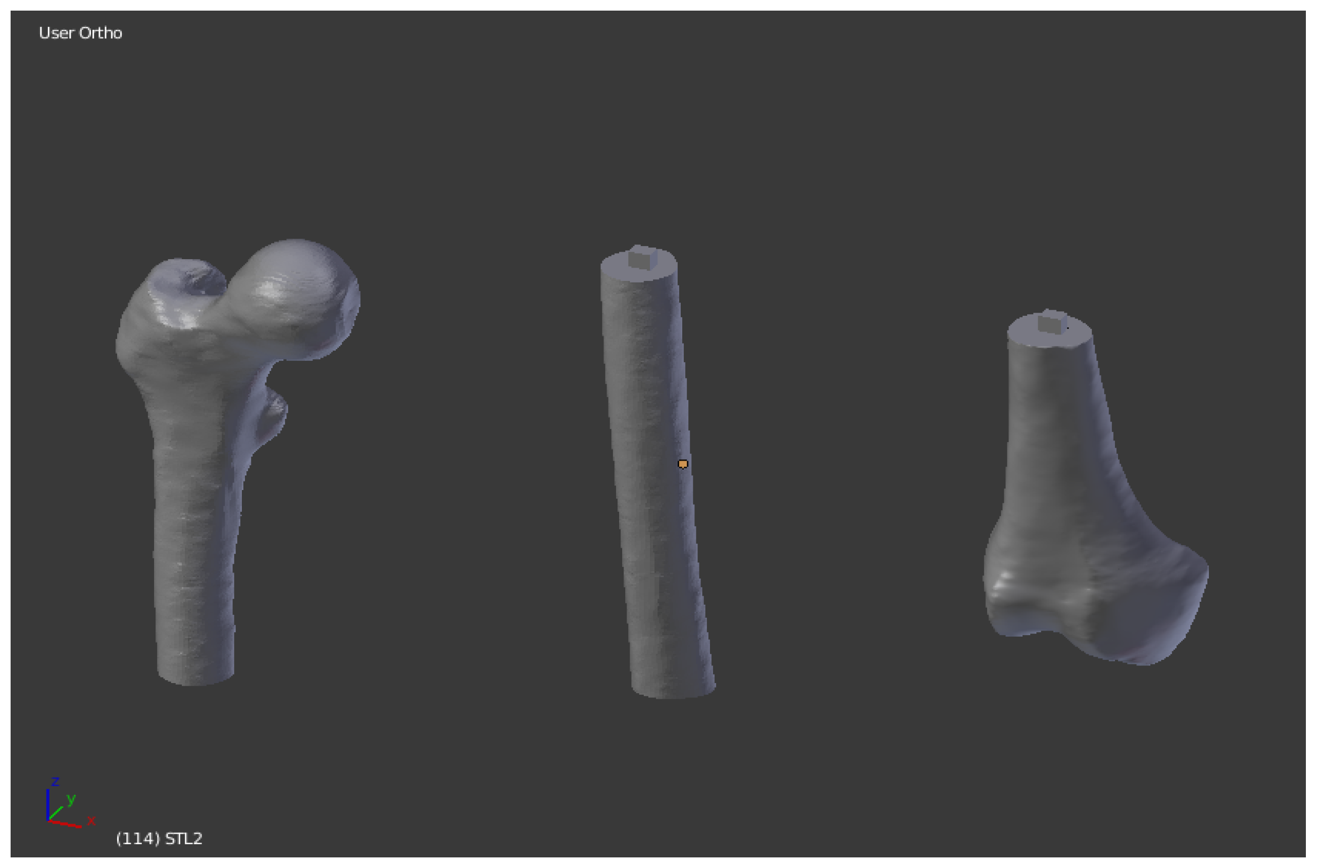
The final result of the operations carried out on Blender is reported in
Figure 25 and
Figure 26:
5.4. Slicing
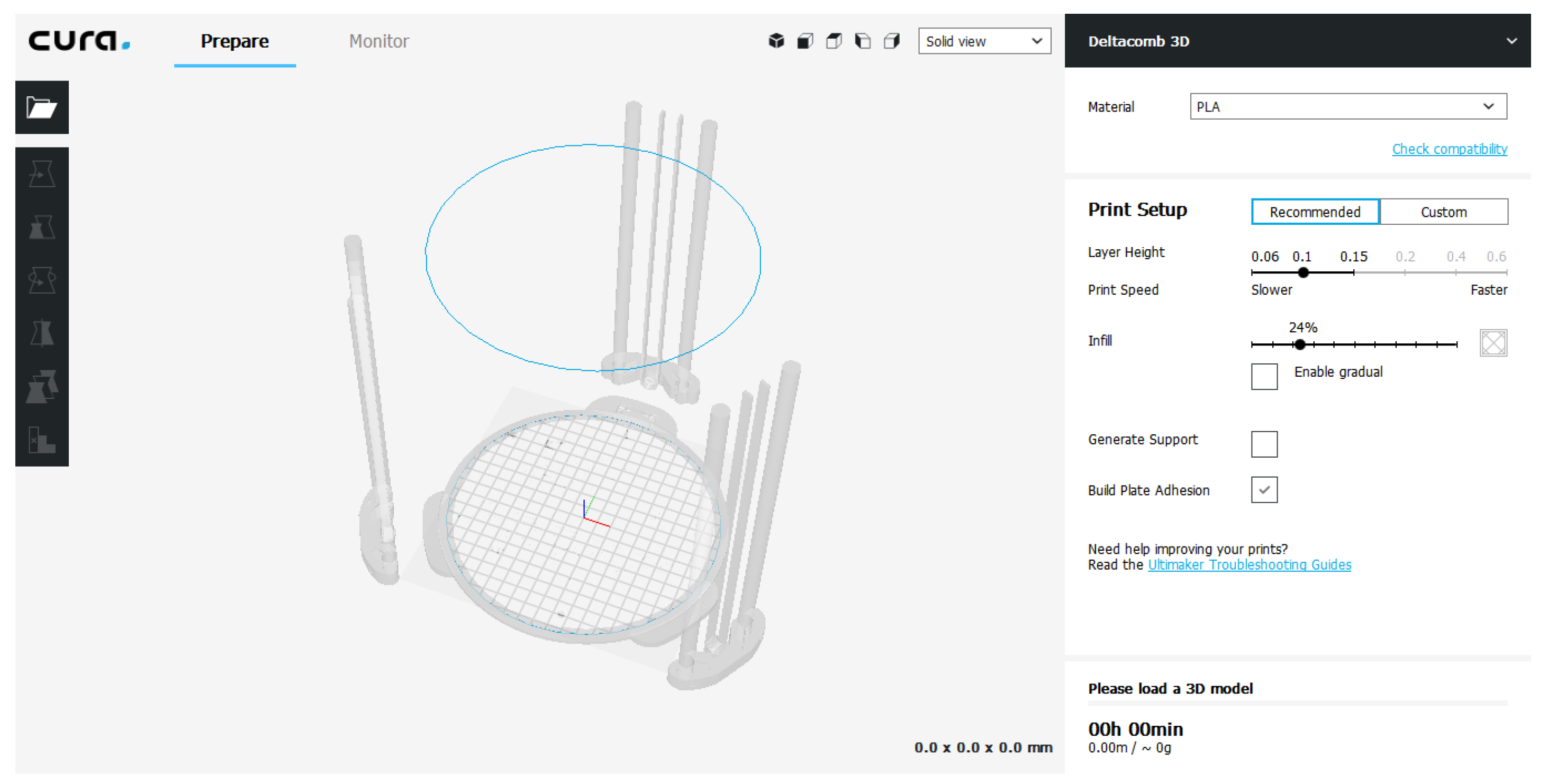
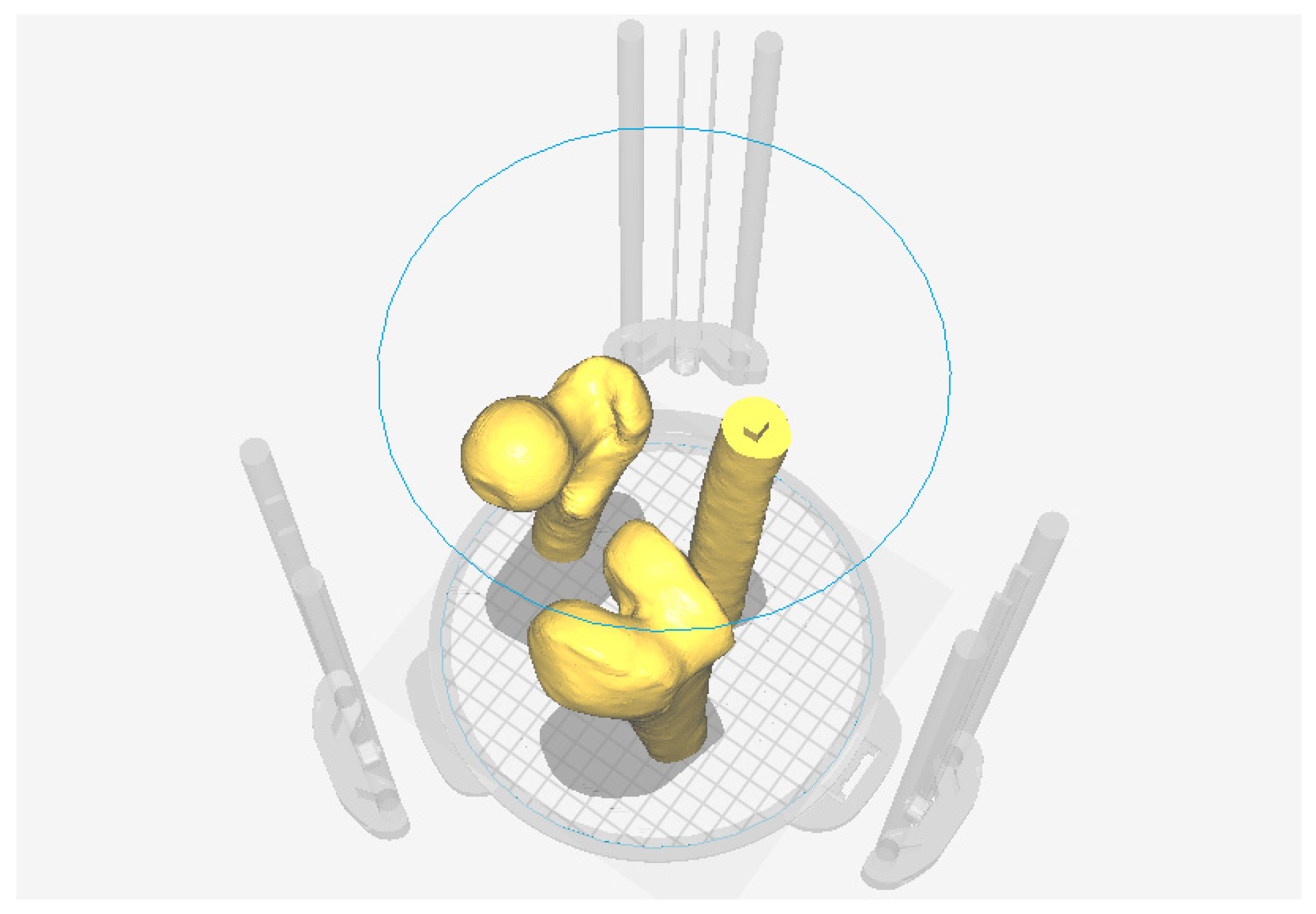
To switch from three-dimensional model display to 3D printing, the Cura slicer is used (
Figure 27).
The 3D environment of the software allows to display the models that must be produced within the printing area, once the type of printer to be used has been defined (
Figure 28).
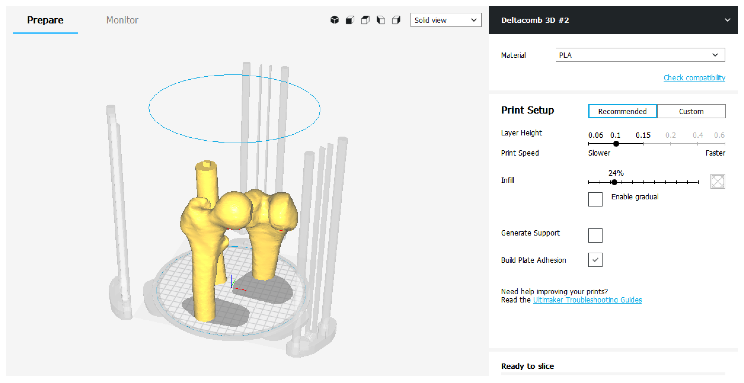
The printing parameters are divided into “Recommended” ones and “Custom” ones.
The “Recommended” settings are nothing more than the minimum and essential parameters to be set to perform slicing. Layer Height and Print Speed represent respectively the height of the layer and the printing speed. They are modified in relation to each other: the higher the layers, the faster it prints and vice versa. The Infill parameter adjusts, in percentage, how much the 3D model must be filled. This index can significantly change the quality of the finished object, as well as its mechanical strength. Generally, for a model that does not need precise mechanical capabilities, an Infill set at 15–25% is more than enough to obtain a good result. In addition to the three fundamental parameters, it is possible to decide whether to generate the Media—Generate Support—to support the cantilevered parts of the model and whether to improve the adhesion to the printing plate—Build Plate Adhesion—expanding the first layer of the object.
If you decide to use the recommended settings, the slicing procedure is completed by exporting the G-code file to be loaded into the 3D printer (
Figure 29).
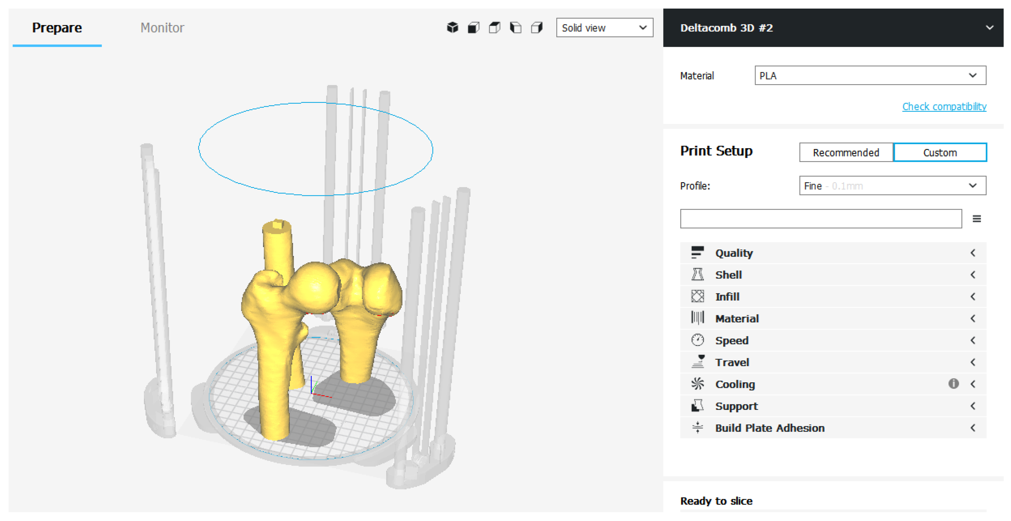
In the Custom mode, on the other hand, there is a series of categories in which all the printing parameters are grouped together—Quality, Shell, Infill, Material, Speed, Cooling, Support, Build Plate Adhesion, Special Modes.
The operator can view and modify the individual advanced Care parameters. Continuing with this slicing mode it is possible to customize every single parameter, obtaining a print file optimized according to the needs (
Figure 30).
6. Benefits
6.1. Preoperative Planning
Additive Manufacturing, in the medical sector, represents an unprecedented technological innovation. 3D printing makes it possible to create three-dimensional anatomical models so that surgeons can examine the patient’s anatomy in a more concrete way, compared to traditional 2D images of X-rays, allowing for a better preoperative planning phase. The ability to view and manipulate a 3D printed model that perfectly represents the anatomical structure which needs surgery can be useful for both patients and surgeons.
In traditional preoperative planning, orthopedic surgeons used simple X-ray and CT-based 2D images to evaluate the patient’s bone anatomy and pathology. The most advanced tomographic image post-processing software can generate 3D images and allows to select patient-specific treatment options by studying all digital images. Despite these advances in image processing technology, anatomy is still seen as a “flat” 3D image. Physical models of the bone, instead, unique to the patient, which can be recreated from the CT image data with 3D printing, not only allow surgeons to have a tactile and visual understanding of the patient’s specific anatomy and pathology, but also to anticipate operational maneuvers in planning orthopedic procedures.
The use of three-dimensional models of bone structures allows for a better understanding of fractures and significantly reduces the degree of variation in the classification of the same and the timing of diagnosis and surgery.
In addition, patient-specific 3D printed models can also be sterilized so that the surgeon can manipulate the model directly on the operating field during the procedure. It can help to confirm the surgical anatomy and the correct operations to be performed in the operating room.
6.2. Education and Surgical Training
3D printed models can be used for preoperative instruction and discussions on surgical strategies. These models can help surgeons, therapists and patients better understand the musculoskeletal pathology. Specific fracture patterns have also been used to improve the approval process in patients with complex diseases: it can increase patient satisfaction, which can now easily understand their medical conditions with real physical models. After surgery, these physical models and their electronic CAD files may be required to construct a library of various types of fractures. Such a collection of fracture patterns are useful educational tools for surgeons, other doctors and medical students.
Despite the use of 3D printed models has not been reported in surgical training in orthopedics, the potential benefits are obvious. Most surgeons train in the operating room: this can put patients at risk when surgeons try to master certain skills in the early stages. With solid and tangible models, older surgeons can pass on their experience to beginners much more easily. In addition to improving the surgeons’ understanding of orthopedic conditions, surgical practice on prototypes created with 3D printing allows them to become more familiar with the patient’s specific conditions before performing similar procedures in the real clinical setting.
6.3. Print of Personalized Medical Instruments
Another of the major benefits of integrating 3D printing into the orthopedic industry is the level of flexibility it offers to medical professionals. With the help of an engineer or a designer, surgeons can customize any medical instrument with exceptional attention to detail and according to their preferences.
In addition to offering surgeons the ability to create customized tools, 3D printing has decentralized the creation of new products and tools: an orthopedic surgeon could design his prototype using CAD software, print his first version and make the necessary changes.
Generally, the design process for creating a new product from scratch is a long and arduous process with a limited ability to create consistent and delicate iterations. The additive manufacturing method of 3D printing changes completely. 3D printing has opened the door to innovation in design and engineering, shortening the iteration cycle and giving inventors the opportunity to improve their designs faster and more accurately than ever before [
11].
The musculoskeletal structures of two people are not exactly the same. Having the ability to customize medical devices allows doctors to better meet the needs of their patients, speed up recovery time and ultimately reduce the inconvenience for both the doctor and the patient.
Although not yet fully perfected and marketed in orthopedics, 3D printing is evidently becoming increasingly adopted in the industry. Inevitably, with the collapse of printing press prices, most hospitals will use 3D printers and tools and will easily become an industry standard. With the development of new technology comes greater accessibility to personalization, something vital for the future of orthopedics.
7. Results
7.1. The Bone
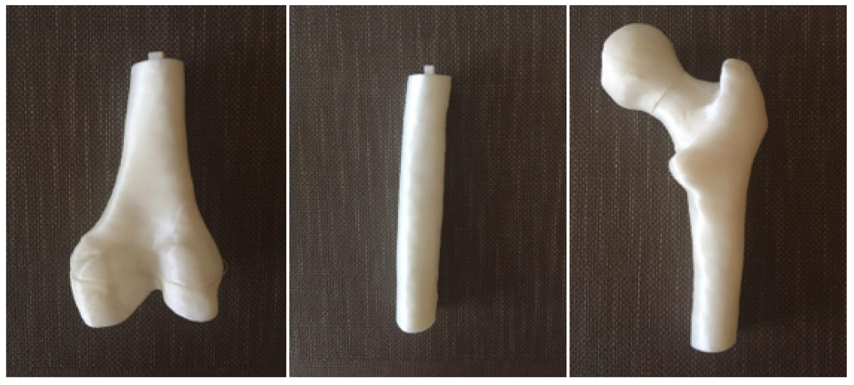
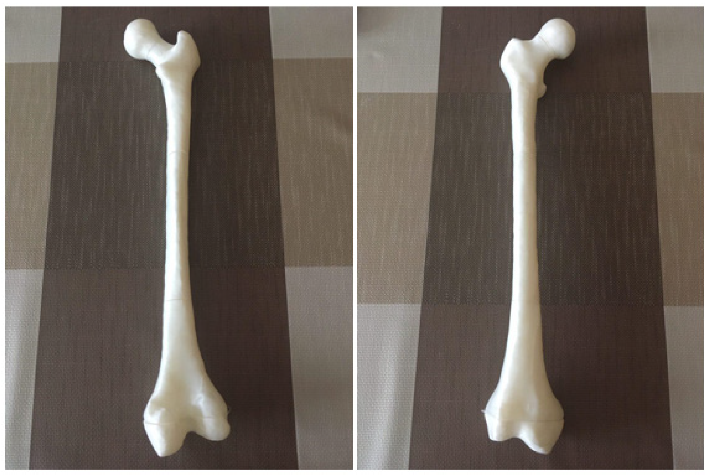
Following the phases of 3D reconstruction of the bone model and the launch of 3D printing, the models 1:1 were reproduced, in white color, made of PLA thermoplastic material, of the three bone segments that make up the femur.
The EZT3D Delta printer from Department of Industrial Engineering of the University of Bologna produced a result with high resolution of details in a printing process lasting about 40 h. The model has the aim of presenting, from a descriptive point of view, the innovative methodology of 3D-printing in the medical field. If it had been a 3D model to be used for the preparation of surgery, it would have been evaluated in the preoperative planning phase by a group of expert surgeons and by the patient himself.
The object, made of PLA, has good general characteristics: it is endowed with good mechanical resistance and hardness, it is very light and smooth to the touch.
The obtained bone model is however not autoclavable: it doesn’t withstand high temperatures. It is not recommended to expose it to temperatures of 50 °C, and already at 60 °C it enters a glass transition. For this reason, the femur produced as a result of the work carried out could not be sterilized in an autoclave for a possible use of maneuvers in the operating room (
Figure 31 and
Figure 32).
7.2. Issues in the 3D Printing Process
Printing 3D objects is not a complex task, but printing three-dimensional models free of defects requires time, patience and a lot of practical experience. To obtain decent results, it is often necessary to carry out several tests, especially if new materials are used.
There are so many variables that can cause printing defects that it is practically impossible to get a perfect 3D object on the first attempt at printing.
The materials used today (ABS, PLA) do not lend themselves to easy post-print processing, which therefore makes it necessary to find the perfect setting and the problems that may affect print quality.
There are three main issues in printing the bone model:
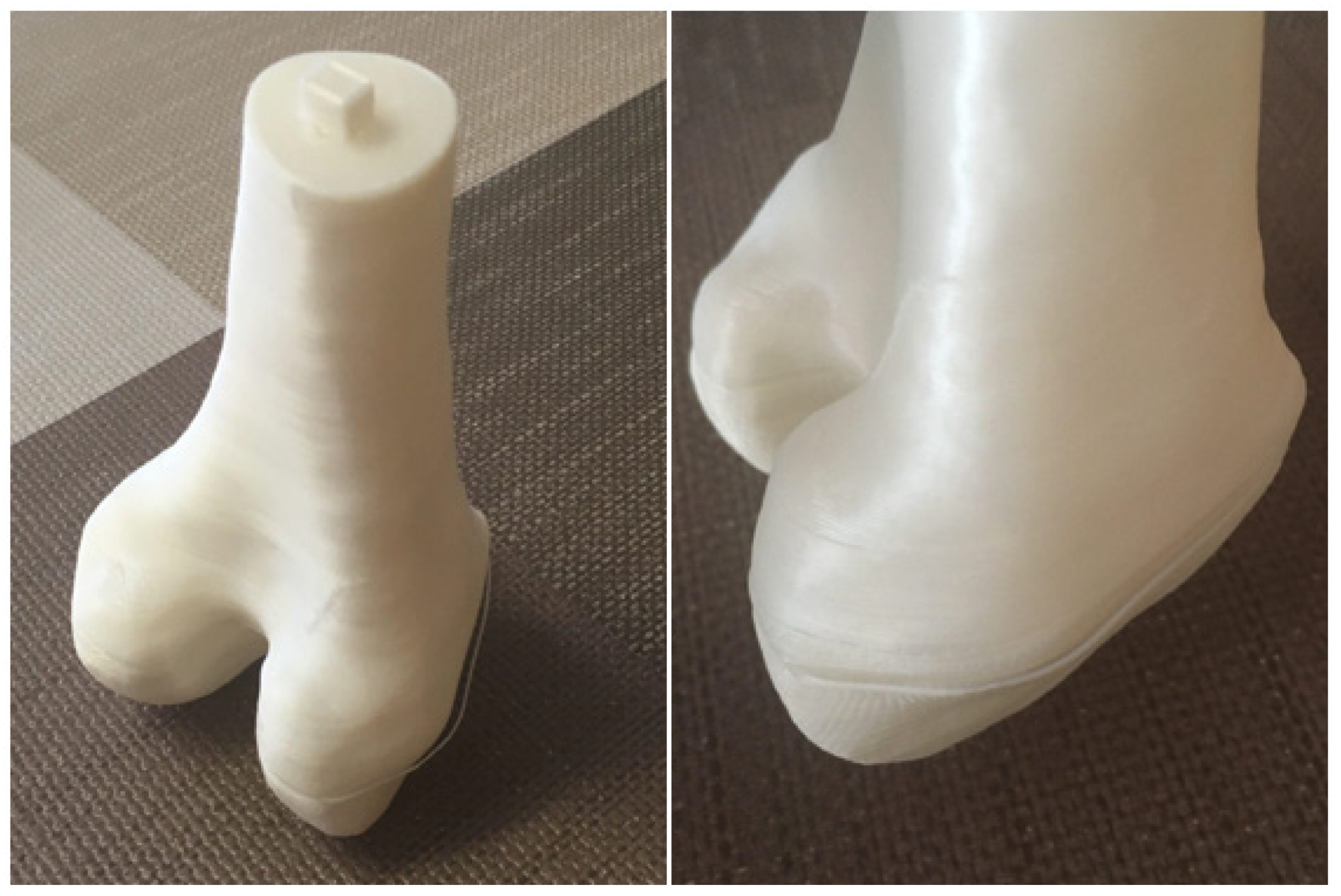
Weak Infill: To save plastic, 3D printing works as to create a solid shell that surrounds an interior composed of a certain partially hidden “honeycomb” pattern. However, depending on the definition of the parameters at the launch of the print, it is possible that the closing plans of the object are not completely solid: if the Infill parameter gets a too low value, gaps or holes may appear between the extrusions that compose these layers. One speaks therefore of “Weak Infill”.
The two bone segments presenting the male part of the pins are characterized by this issue, in the horizontal plane near the connection. This defect can be seen in
Figure 33, on the left, compared with a correct degree of filling of the horizontal plane on which the female was obtained, on the right, the latter due to the fact that this surface was totally resting on the printing surface, therefore not influenced by the Infill parameter.
Bad layer adhesion: 3D printing builds one layer at a time: each successive layer is printed above the previous one until the desired three-dimensional shape is created. However, to have a strong and reliable shape, it is necessary to ensure that each layer is properly bonded to the underlying layer. If the layers do not come together well enough, the final model can be divided or separated.
We can see in an area of the 3D model of the distal epiphysis that some layers are detached. This defect could be caused by a height of the single layer too high (it is a good rule that the layer height is 20% less than the nozzle diameter) or from an uncorrected cooling of the deposited material (
Figure 34).
Warping
When printing larger models, the first layers of the object tend to curl and warp. This curl can be so severe that one part of the model separates from the bed and the whole print can fail. This behavior is particularly common when printing parts with very wide bases with high temperature materials.
For example, consider the printing of a PLA cylinder with a very high base area, a height of only 10 layers and a high degree of filling: the material deposited as the first layers will not have time to quickly cool down, to due to the close presence of the nozzle, at high temperature, which deposits new molten material.
As the printing proceeds, each layer does not cool optimally, tends to warp up to a possible curl or separation of that area of the object. This type of defect was not found in the methodology applied in this paper: the three printed bone segments did not show warping defects.
Defect of support structures: When the model to be printed has protrusions or cantilevered parts, it is necessary to add supports from the slicing program to hold the structure together during prototyping, which will be easily removed when the process is finished.
When there are many support structures with a very limited and therefore fragile base, the head which deposits molten material can cause it to fall. Without a support, the deposited material does not have a base to lean on and the print is compromised. This type of defect was not found in our case of study, since the bone model doesn’t provide any cantilevered part.
8. Conclusions and Future Developments
The method has allowed us to obtain a three-dimensional bone model in PLA that perfectly reflects the anatomical structure of the bone subject to the CT scan. The printed model is patient-specific: this allows a better understanding of the complex anatomy, and brings benefits in the surgeon-patient communication, in the evaluation of the diagnosis, with greater surgical safety and reductions of the operative time have also been noted.
In order to create the bone model, a 3D reconstruction process was performed, characterized by the transformation of the flat image contained in the outcome of a CT scan into a three-dimensional surface, which was subsequently modified and optimized, through the use of special software, up to be compatible with the launch of a correct 3D printing [
12,
13].
Each software has played a fundamental role in the method: by InVesalius, a simple software to convert the tomographic image into a three-dimensional anatomical surface, passing through the MeshLab and Blender, graphics software used to clean the coarse, previously exported mesh, making it functionally and aesthetically suitable for printing, up to Cura, slicing software with which to start and manage the prototyping of the created mesh.
The results obtained from the work carried out showed the effectiveness of having a 3D prototype for the surgeons. The surgeons expressed their appreciation, providing positive feedback on the advantages that this technology can bring, particularly in the preoperative diagnosis phase.
The collaboration between the Department of Industrial Engineering of the University of Bologna and the Rizzoli Orthopedic Institute is leading to various applications of the innovative methodology studied, most of which concern cases of flatfoot in the department of Pediatric Orthopedics, where Dr. Maredi performs its functions.
However, it is important to keep in mind that this type of research nowadays focuses on a very small number of patients and the applications of the method performed are still few.
A recommendation for further future research could be to carry out a similar study expanding the number of patients involved in order to obtain a quantitative and not only qualitative assessment of the satisfaction of medical personnel.
The main future development of the methodology is the use of augmented reality (AR), the modern vision technology of perceived reality with the integration of information in digital format. This futuristic concept is expanding to include medical and health care: the augmented reality enters the operating room thanks to a wearable viewer—HoloLens—that will assist and guide the surgeon’s eyes and hands during surgery.
The presented method is perfectly suitable for displaying the model in augmented reality. The mesh created, once optimized using Blender, will not be imported into slicing software, but will be loaded directly onto HoloLens. The surgeon will not be able to physically touch the anatomical structure in the preoperative phase but, by wearing HoloLens, he will be able to visualize the 3D model directly overlaid on the intraoperative images during the surgical procedure. This development takes the name of “virtual prototyping” and represents an alternative, or an expansion, of the “physical prototyping” described by the present innovative diagnostic method.

 ,
, 


