You are currently viewing a new version of our website. To view the old version click .
Symmetry
  • Article
  • Open Access

5 December 2019

Modified Advanced Encryption Standard Algorithm for Information Security

,
,
,
and
1
Computer Science Department, University of Ilorin, Ilorin 240103, Kwara State, Nigeria
2
Computer Science Department, Gombe State University, Gombe 760214, Gombe State, Nigeria
3
Data and Information Security Research Group, Computer Science Department, Landmark University, Omu-Aran 251101, Kwara State, Nigeria
*
Author to whom correspondence should be addressed.

Abstract

The wide acceptability of Advanced Encryption Standard (AES) as the most efficient of all of the symmetric cryptographic techniques has further opened it up to more attacks. Efforts that were aimed at securing information while using AES is still being undermined by the activities of attackers This has further necessitated the need for researchers to come up with ways of enhancing the strength of AES. This article presents an enhanced AES algorithm that was achieved by modifying its SubBytes and ShiftRows transformations. The SubBytes transformation is modified to be round key dependent, while the ShiftRows transformation is randomized. The rationale behind the modification is to make the two transformations round key dependent, so that a single bit change in the key will produce a significant change in the cipher text. The conventional and modified AES algorithms are both implemented and evaluated in terms avalanche effect and execution time. The modified AES algorithm achieved an avalanche effect of 57.81% as compared to 50.78 recorded with the conventional AES. However, with 16, 32, 64, and 128 plain text bytes, the modified AES recorded an execution time of 0.18, 0.31, 0.46, and 0.59 ms, respectively. This is slightly higher than the results obtained with the conventional AES. Though a slightly higher execution time in milliseconds was recorded with the modified AES, the improved encryption and decryption strength via the avalanche effects measured is a desirable feat.

1. Introduction

The advancement in Information and Communication Technology (ICT) has made internet one of the major mediums through which information is being shared in this 21st century. However, the confidentiality, integrity, and availability of information shared over public network still remains an open issue [1]. Information hiding techniques using watermarking and steganography as well as cryptography have been widely explored to ensure the security of information transmitted over an unsecured network. With emphasis on cryptography, information security is guaranteed by making a secret message unreadable to a third party, but accessible by the sender and recipient alone while using one or more secret keys. Cryptographic techniques could be symmetric—if the same key is used for encryption and decryption or asymmetric—if different keys are used for encryption and decryption [2]. Symmetric cryptographic techniques are the most appropriate when a large amount of data is to be secured [3]. Of the available symmetric cryptographic techniques, such as Data Encryption Standard (DES), Triple DES, and Advanced Encryption Standard (AES), AES is the most common and widely used [4]. However, several attacks that aimed at undermining the strength of AES algorithm have been reported in the literature. Differential fault analysis attacks that inject faults into AES structure with the aim of retrieving the secret information were reported in [5], while cache timing attack, which uses side channel information, such as power consumption statistics, timing information, and cache contents to infer the unknown key used in data encryption, was reported in [6]. Most recently, related-key differential attacks was reported in [7]. In this attack, the cryptanalyst queries the block ciphers with plaintext pairs to deduce the secret key that was used. Similarly, cipher strength analysis carried out by cipher analysts have revealed that with the current trend of increasing computational power, eight out of ten rounds of AES has been brute forced successfully and soonest the remaining two rounds may be broken [8]. This has called for the need to urgently explore techniques that could further strengthen the AES algorithm. Therefore, this article introduces an enhanced AES algorithm that was achieved by modifying its SubBytes and ShiftRows transformations. The rationale behind the modification is to make the two transformations round key dependent, so that a change to any bit of the key will result to a significant change in the cipher text. The rest of the paper is organized, as follows: Section 2 explained the existing AES algorithm, its structure, and various transformation stages. A review of recent works as regards AES modification was carried out in Section 3, while the proposed methodology was explained in details in Section 4. The result of the modified AES algorithm, its performance evaluation using avalanche effect, execution time is presented in Section 5. A comparative analysis of the modified AES with those that were obtained from existing works is also presented in Section 5. The study’s conclusion is provided in Section 6.

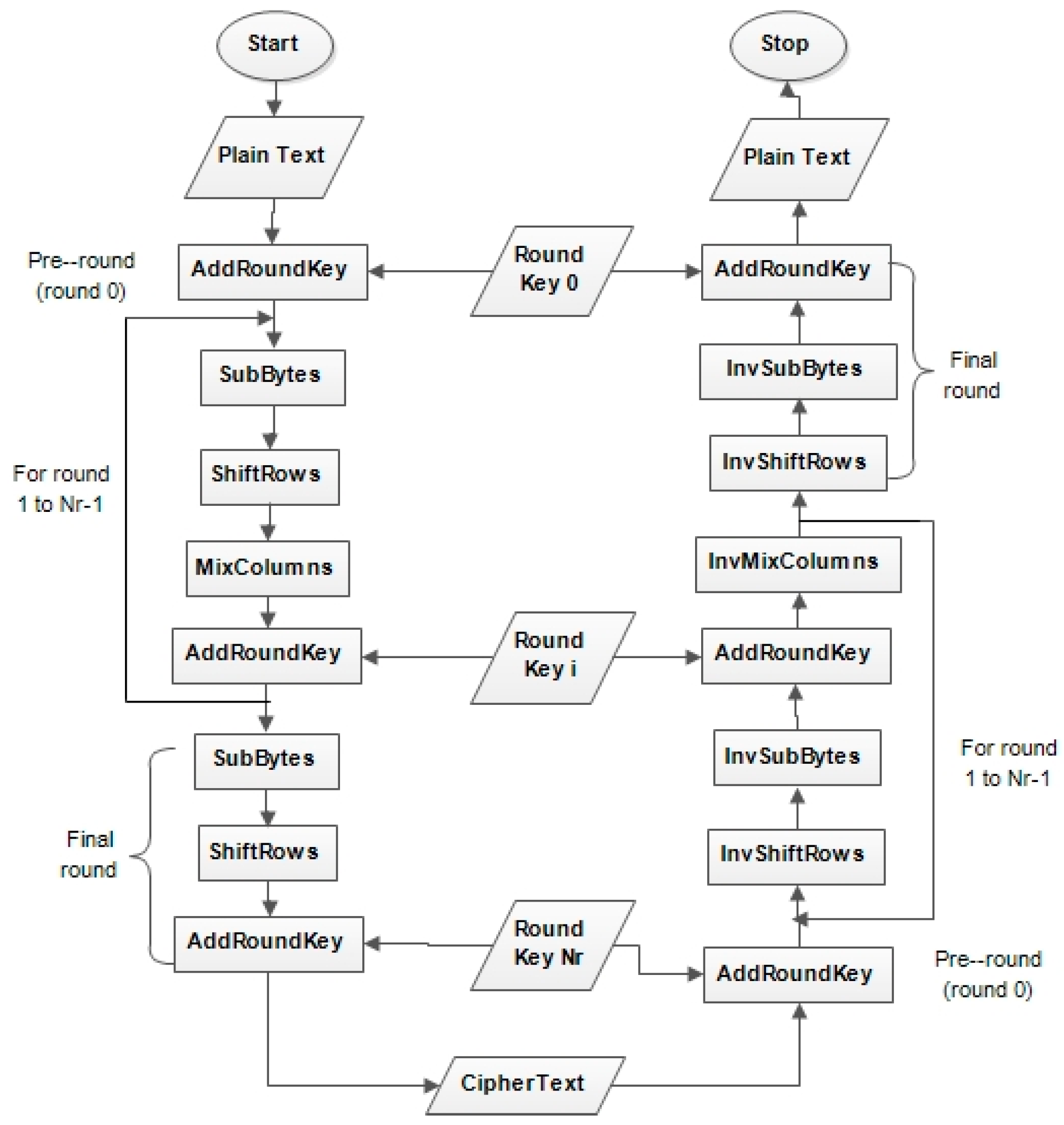
2. Existing AES Algorithm

The AES algorithm is a symmetric key algorithm that was established as the standard for encrypting digital data by the US National Institute for Standard and Technology (NIST). It is an iterative round block cipher that works on 128bit plaintext using three different key lengths 128, 192, and 256 bits [9]. The key length determines the number of encryption and decryption rounds to be performed which could be 10, 12, and 14 rounds for 128, 192, and 256-bit key length, respectively. It is believed that the larger the key length, the higher the cryptographic strength [9]. The AES algorithm consists of four invertible transformations: SubBytes, ShiftRows MixColumns, and AddRoundKey, as shown in Figure 1.
Figure 1. Structure of the Advance Encryption Standard (AES) Algorithm.
All of these transformations are performed in all the encryption rounds, except the final round, where the MixColumns transformation is omitted to make the encryption and decryption scheme symmetric, these transformations are described below:
(i)
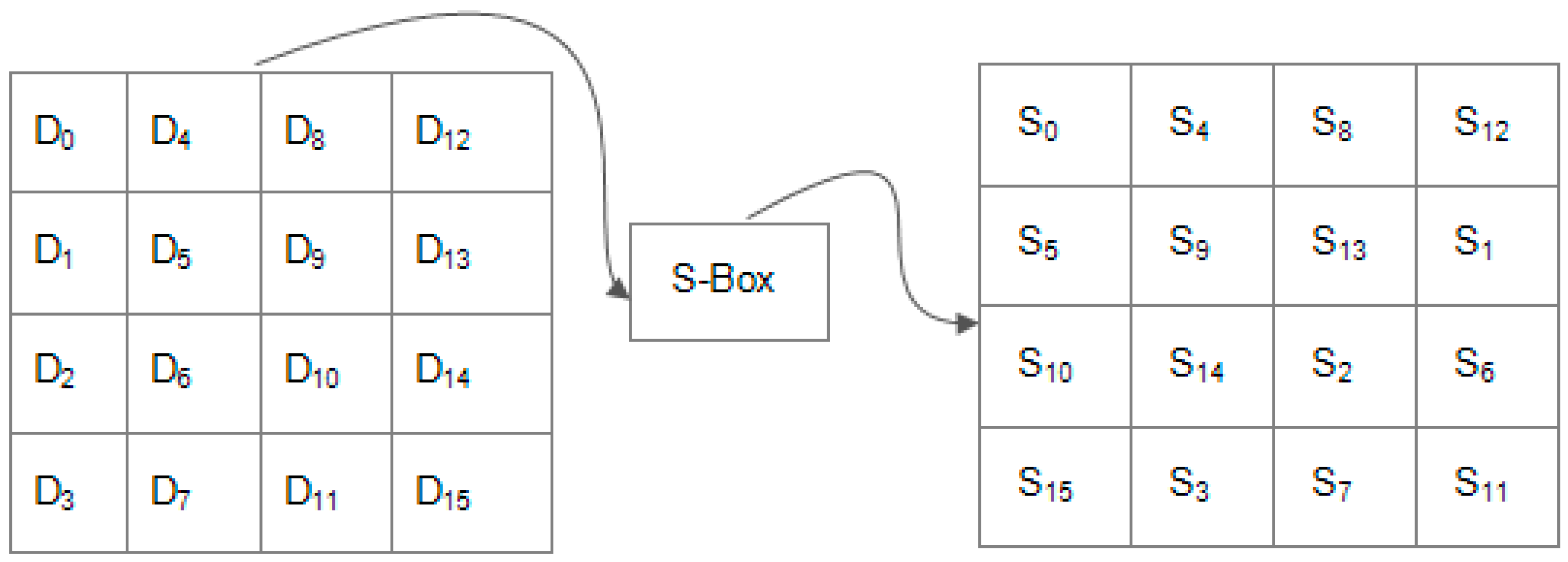
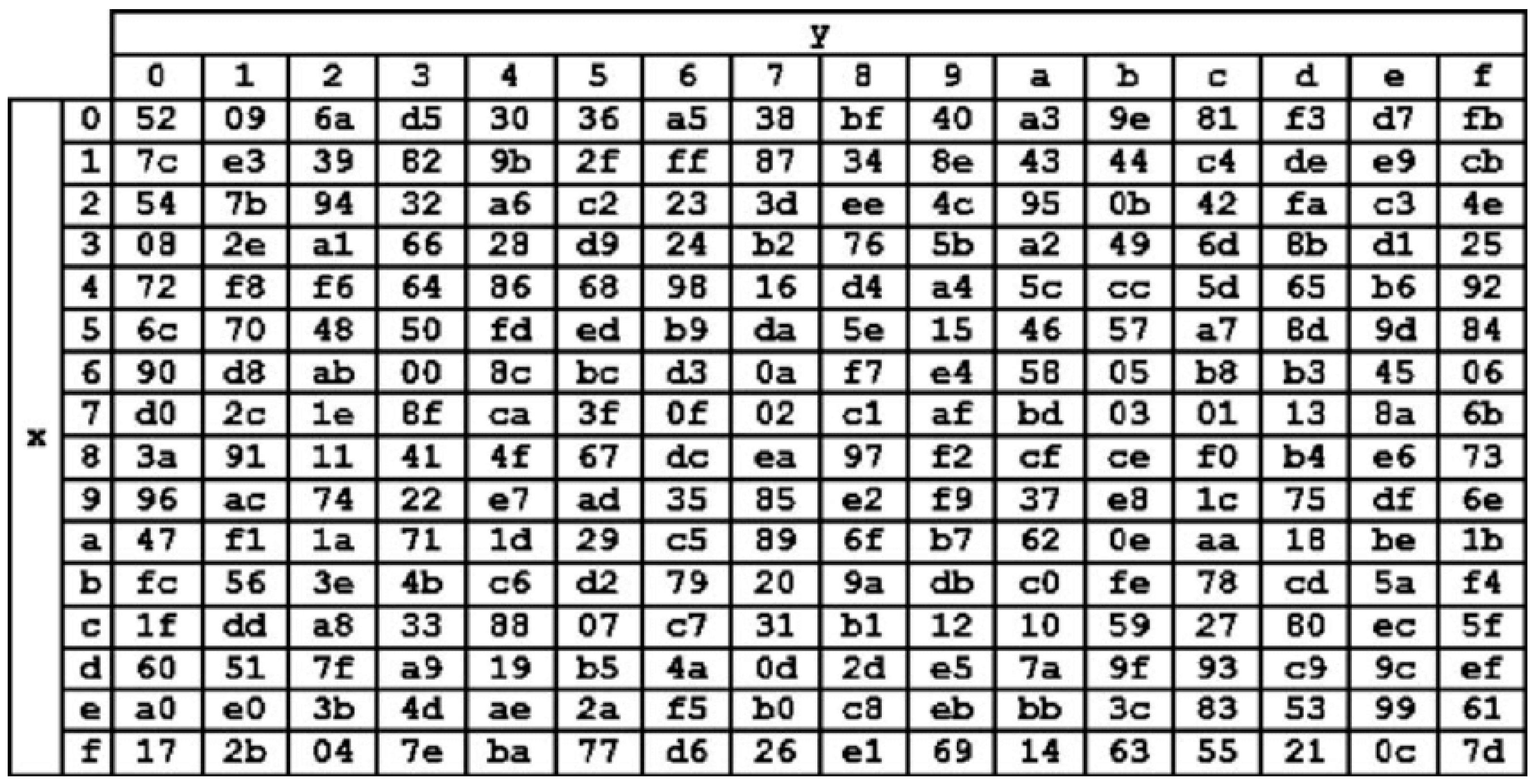
SubBytes Transformation: as shown in Figure 2, SubBytes transformation is the only non-linear and invertible byte transformation that replaces each byte of the input data block (D0, …, D15) by the row (first 4-bits) and column (second 4-bits) of a 16 × 16 Substitution Box (S-Box). The S-Box, as shown in Figure 3, has special mathematical properties that ensure that changes in individual state bits propagate quickly across the cipher text, which introduces confusion. Inverse substitution table (InvS-Box) is used during decryption to undo the effect of the SubBytes transformation.
Figure 2. SubBytes Transformation.
Figure 3. Substitution Box [10].
(ii)
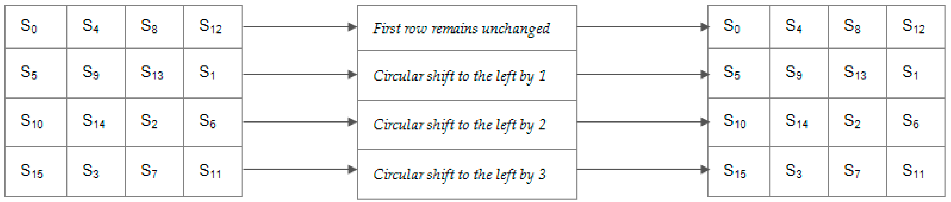
ShiftRows Transformation: This manipulates the rows of the state by using a certain offset to shift the bytes in each row, as shown in Figure 4. This is carried out to ensure that the columns of the state are not independently encrypted. During this operation, the first row remains unchanged, while one-byte, two-byte, and three-byte circular shift operation is performed on the second, third, and fourth rows, respectively. For the decryption process, the first row remains unchanged, while the other rows are shifted to the right based on the same offset used to shift them to the left during encryption process
Figure 4. ShiftRows Transformation.
(iii)
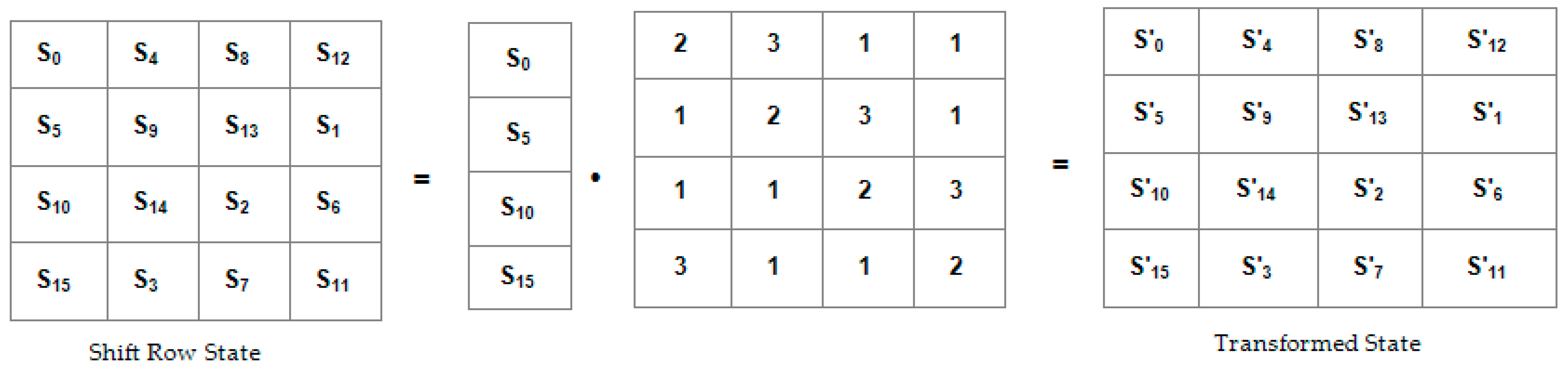
MixColumns Transformation: This is a linear diffusion process that sees the columns of the state as coefficients of polynomial of order x7. It manipulates all the columns of the state by carrying out multiplication and addition operation on their bytes. Exclusive OR (XOR) is used for the addition operation while modulo   m ( x ) = x 8 + x 4 x 3 + x + 1 is used for the multiplication operation. As shown in Figure 5, each column of the state obtained from shiftrow transformation is multiplied by a mixing matrix to obtain the transformed matrix. With this manipulation, the initial setting of the cipher text is changed, such that no bytes look similar. Inverse MixColumns is used to undo this transformation during the decryption process.
Figure 5. MixColumns Transformation.
(iv)
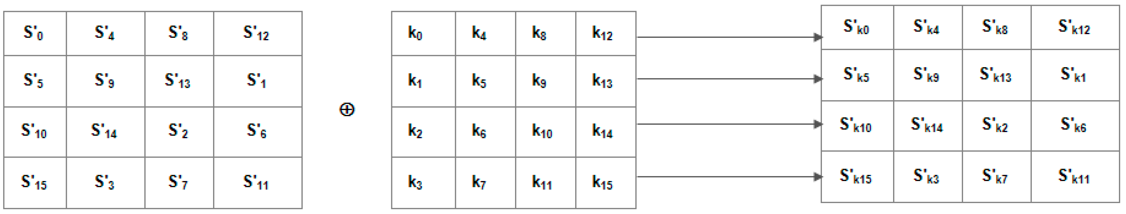
AddRoundKey Transformation: This is the last transformation that will be done for each round. As shown in Figure 6, an addition operation between the bytes of the transformed state and the round key is carried out while using XOR.
Figure 6. AddRoundKey Transformation.

4. Proposed Methodology

This section presents the methodology adopted in this study in detail.

4.1. Modified SubBytes Transformation

AES SubBytes transformation was modified to make it round key dependent; this is to ensure that a change in the key is easily discovered in the cipher text. To achieve that, the 16 bytes round key was used to obtain four eight-bit keys X O R k e y 0 ,     X O R k e y 1 ,     X O R k e y 2 ,     X O R k e y 3 by XORing all the bytes of the corresponding row ( R o w i ) in the round key matrix, as shown in Equation (2). After obtaining the X O R k e y s , each X O R k e y i as shown in Equations (3)–(6) was then added to all of the bytes in the corresponding row ( R o w i ) of the state matrix before substituting the values in the S-Box. Mathematically, given the state S and a round key K, represented as a 4 × 4 matrices:
S=S 0,0S 0,1S 0,2S 0,3and K = K0,0K0,1K0,2K0,3
S 1,0S 1,1S 1,2S 1,3K1,0K1,1K1,2K1,3
S 2,0S 2,1S 2,2S 2,3K2,0K2,1K2,2K2,3
S 3,0S 3,1S 3,2S 3,3K3,0K3,1K3,2K3,3
X O R k e y i =   K i , 0     K i , 1     K i , 2     K i , 3 ,   where   i   =   0   t o   3
Alternatively,
X O R k e y 0 =   K 0 , 0     K 0 , 1     K 0 , 2     K 0 , 3
X O R k e y 1 =   K 1 , 0     K 1 , 1     K 1 , 2     K 1 , 3
X O R k e y 2 =   K 2 , 0     K 2 , 1     K 2 , 2     K 2 , 3
X O R k e y 3 =   K 3 , 0     K 3 , 1     K 3 , 2     K 3 , 3
The new state matrix, S′ was obtained while using Equation (7).
S i , j = S i , j     X O R k e y i ,   where   j   =   0   t o   3   where   i   ranges   from   0   t o   3
The operation can be seen clearly from the matrix below:
S ’ =S 0,0 ⨁ Key0S 0,1 ⨁ Key0S 0,2 ⨁ Key0S 0,3 ⨁ Key0
S 1,0 ⨁ Key1S 1,1 ⨁ Key1S 1,2 ⨁ Key1S 1,3 ⨁ Key1
S 2,0 ⨁ Key2S 2,1 ⨁ Key2S 2,2 ⨁ Key2S 2,3 ⨁ Key2
S 3,0 ⨁ Key3S 3,1 ⨁ Key3S 3,2 ⨁ Key3S 3,3 ⨁ Key3
The resultant state matrix S′ is given as follows:
S′= S0,0S0,1S0,2S0,3
S1,0S1,1S1,2S1,3
S2,0S2,1S2,2S2,3
S3,0S3,1S3,2S3,3
After obtaining the new state matrix S′, the bytes are then substituted in the substitution table (S-Box) using normal SubBytes operation, as shown in Equation (8):
S i , j = S u b s t i t u t i o n B o x [ S i , j ] ,   where   j   =   0   t o   3   for   every   i   =   0   t o   3

4.2. Modified Inverse SubBytes Transformation

To obtain the modified inverse SubBytes operation, the SubBytes transformation was proved to be invertible, as shown in Equation (9). Given two polynomials f ( x )   and   f ( k ) operating in Galois Field 28 (GF (28)), such that:
f ( h ) = f ( x )     f ( k ) ,   and   f ( x ) = ( f ( x )   f ( k ) ) f ( k ) = f ( h )     f ( k )
The proof is given, as follows:
Given two hexadecimal numbers ED (11101101 in binary) and BF (10111111 in binary), the number x, which is the XOR of ED and BF can be obtained by adding BF to ED while using and exclusive OR operation. The operation is shown, as follows:
ED and BF can be expressed in terms of polynomial f ( x )   and   f ( k ) , respectively, in Galois Field 28 (GF (28)) as:
f ( x ) = x 7 + x 6 + x 5 + x 3 + x 2 + 1 = E D
f ( k ) = x 7 + x 5 + x 4 + x 3 + x 2 + x 1 + 1 = B F
Therefore,
f ( h ) = f ( x )     f ( k )   =   x 7 + x 6 + x 5 + x 3 + x 2 + 1   x 7   + x 5 + x 4 + x 3 + x 2 + x 1 + 1 =   x 6 + x 4 + x 1
f ( h ) = x 6 + x 4 + x 1 = 01010010 in binary, and 52 in hexadecimal. To prove that f ( x ) = ( f ( x )   f ( k ) ) f ( k ) = f ( h )     f ( k ) , using the polynomials f ( h )     f ( k ) , we obtain:
f ( x ) = f ( h )   f ( k ) = x 6 + x 4 +   x 1   x 7 + x 5 + x 4 + x 3 + x 2 + x 1 + 1 =   x 7 + x 6 + x 5 + x 3 + x 2 + 1
Since f ( x ) = ( f ( x )   f ( k ) ) f ( k ) = f ( h )     f ( k ) , the SubBytes operation is proven to be invertible.
During the inverse SubBytes operation, the substitution is done before XORing the state matrix with the   X O R k e y s using
S i , j = I n v e r s e S u b s t i t u t i o n B o x [ S i , j ] ,   where   j   =   0   t o   3 ,   for   every   i   =   0   t o   3
The matrix S′ is then obtained after the substitution as:
S ’ = S0,0S0,1S0,2S0,3
S1,0S1,1S1,2S1,3
S2,0S2,1S2,2S2,3
S3,0S3,1S3,2S3,3
Hence, the original state S is obtained by XORing the S′ matrix with the X O R k e y s using Equation (15):
S i , j = S i , j     X O R k e y i ,   where   j = 0 to 3   for   each   i from   0 to 3
The inverse SubBytes operation is shown in the matrix below:
S =S’ 0,0 ⨁ Key0S’ 0,1 ⨁ Key0S’ 0,2 ⨁ Key0S’ 0,3 ⨁ Key0
S’ 1,0 ⨁ Key1S’ 1,1 ⨁ Key1S’ 1,2 ⨁ Key1S’ 1,3 ⨁ Key1
S’ 2,0 ⨁ Key2S’ 2,1 ⨁ Key2S’ 2,2 ⨁ Key2S’ 2,3 ⨁ Key2
S’ 3,0 ⨁ Key3S’ 3,1 ⨁ Key3S’ 3,2 ⨁ Key3S’ 3,3 ⨁ Key3
The resultant matrix S, which is the original state is obtained, as follows:
S = S0,0S0,1S0,2S0,3
S1,0S1,1S1,2S1,3
S2,0S2,1S2,2S2,3
S3,0S3,1S3,2S3,3
The proof above shows that the SubBytes operation is invertible, since
S u b s t i t u t i o n B o x [ S i , j     X O R k e y i ] = I n v e r s e S u b s t i t u t i o n B o x [ S i , j ]     X O R k e y i ,
where j = 0 to 3, for each i from 0 to 3.

4.3. Modified ShiftRows Transformation

Modification to the ShiftRows operation was achieved by randomizing the entire operation. In the conventional AES algorithm, the ShiftRows operation depends on a fixed number, called the offset, which determines the number of byte position(s) each row of the state will be shifted. With this modification, the operation does not have to depend on the fixed offset, it now depends on a number, called the Rank Number (RNo), which is obtained by manipulating each row of the state matrix with the corresponding row of the round key matrix. The rows of the state are shifted based on the rank number obtained. To obtain the rank number using a state matrix S and a round key matrix K, the following steps were adopted:
S=S 0,0S 0,1S 0,2S 0,3and K = K0,0K0,1K0,2K0,3
S 1,0S 1,1S 1,2S 1,3K1,0K1,1K1,2K1,3
S 2,0S 2,1S 2,2S 2,3K2,0K2,1K2,2K2,3
S 3,0S 3,1S 3,2S 3,3K3,0K3,1K3,2K3,3
  • Step 1: Each row (Rowi) of the state matrix was added to the corresponding row in the round key matrix using XOR to obtain a 4-byte vector called State-Key (SKey) vector.
  • Step 2: The four-byte of the State-Key vector are then XORed together to obtain an 8-bit value called the Rank Value (RVal).
  • Step 3: The eight-bit Rank Value (RVali) is then stored in corresponding Rowi of the state matrix.
  • Step 4: Steps 1–3 will be repeated for the remaining rows Row1 to Row3
  • Step 5: Attach Rank Number (RNo) to the Rank Values obtained in Step 3 above for each of the rows of the state (Row0 to Row3) in ascending order with the minimum rank value having 1 as the rank number while the maximum rank value has 4 as the Rank Number.
The above steps can be mathematically expressed, as follows:
The State–Key (SKey) vector is obtained using Equation (16), such that:
S K e y i = ( ( S i , 0     K i , 0 ) ,   ( S i , 1     K i , 1 ) ,   ( S i , 2     K i , 2 ) ,   ( S i , 3     K i , 3 ) )
Equation (16) can be further reduced into Equation (17), such that:
S K e y i = ( S K i , 0 ,   S K i , 1 , S K i , 2 , S K i , 3 ) ,   where   S K i , j = S i , j     K i , j
Alternatively, Equation (17) can be decomposed into Equations (18)–(20):
S K e y 0 = ( S K 0 , 0 ,   S K 0 , 1 , S K 0 , 2 , S K 0 , 3 )
S K e y 1 = ( S K 1 , 0 ,   S K 1 , 1 , S K 1 , 2 , S K 1 , 3 )
S K e y 2 = ( S K 2 , 0 ,   S K 2 , 1 , S K 2 , 2 , S K 2 , 3 )
S K e y 3 = ( S K 3 , 0 ,   S K 3 , 1 , S K 3 , 2 , S K 3 , 3 )
The Rank Values (RVals) are then obtained using Equation (22), such that:
R V a l i = ( S K i , 0     S K i , 1     S K i , 2     S K i , 3 ) ,   where   i   =   0   to   3
Alternatively, Equation (22), which is generic, can further be broken into four independent equations representing each row of the state shown in Equations (23)–(26):
R V a l 0 =   S K 0 , 0     S K 0 , 1     S K 0 , 2     S K 0 , 3
R V a l 1 =   S K 1 , 0     S K 1 , 1     S K 1 , 2     S K 1 , 3
R V a l 2 =   S K 2 , 0     S K 2 , 1     S K 2 , 2     S K 2 , 3
R V a l 3 =   S K 30     S K 3 , 1     S K 3 , 2     S K 3 , 3
After obtaining the Rank Values (RVals), Rank Number (RNo) is then attached to these values in ascending order, with RNo of 1 being attached to the smallest RVal, while RNo of 4 is attached to the biggest RVal.
Lastly, each row of the state is then shifted R N o 1 positions to the left. This means that the row with RNo = 1 is not shifted, the one with RNo = 2 is shifted one-byte position to the left, followed by the row with RNo = 3, which is shifted two-byte position to the left, and lastly, the row with the highest rank number, RNo = 4 is shifted three-byte position to the left. Table 1 displays the above statements.
Table 1. Relationship Between Rank Number and Number of Byte Position to Shift Each Row in Modified ShiftRows Operation of the Enhanced AES.
Given the state matrix S and round key matrix K, the modified ShiftRows operation is described below:
S = 4D87F297and K = 115575A1
EC6E4C901F4453CA
4AC346E783E6903D
8CD895A6D431779F
The State-Key (SKey) vectors are obtained, as follows:
S K e y 0 = ( ( 4 D     11 ) ,   ( 87     55 ) ,   ( F 2     75 ) ,   ( 97     A 1 ) ) = ( 5 C ,   D 2 ,   87 ,   36 )
S K e y 1 = ( ( E C     1 F ) ,   ( 6 E     44 ) ,   ( 4 C     53 ) ,   ( 90     C A ) ) = ( F 3 ,   2 A ,   1 F ,   5 A )
S K e y 2 = ( ( 4 A     83 ) ,   ( C 3     E 6 ) ,   ( 46     90 ) ,   ( E 7     3 D ) ) = ( C 9 ,   25 ,   D 6 ,   DA )
S K e y 3 = ( ( 8 C     D 4 ) ,   ( D 8     31 ) ,   ( 95     77 ) ,   ( A 6     9 F ) ) = ( 58 ,   E 9 ,   E 2 ,   39 )
The Rank Values (RVals) are then obtained, as follows:
R V a l 0 =   5 C     D 2     87     36 = 3 F
R V a l 1 =   F 3     2 A     1 F     5 A = 9 C
R V a l 2 =   C 9     25     D 6     DA = E 0
R V a l 3 =   58     E 9     E 2     39 = 6 A
Table 2 depicts the Rank Values (RVals), their corresponding Rank Numbers (RNos), and state row number.
Table 2. Rank Values with their Corresponding Rank Numbers.
From Table 2, based on the rank numbers that were obtained for each row, the corresponding row will have to shift one less than the RNo value of that row. Row 0 will not shift, Row 1 will have to shift two-byte position to the left, row 2 will have to shift three-byte position to the left, and finally row 3 will have to shift one-byte position to the left. After performing these ShiftRows operations on the above state while using the state and the round key matrices S and K, the state matrix obtained is given as S and S′ for state matrix before and after the modified ShiftRows operation, respectively:
S = 4D87F297S’ = 4D87F297
EC6E4C904C90EC6E
4AC346E7E74AC346
8CD895A6D895A68C

4.4. Modified Inverse ShiftRows Transformation

The rank number computation for the modified InvShiftRows operation remains the same as that of modified ShiftRows operation since the round keys are read in reverse order during decryption process. The only difference is the direction to which the rows of the state matrix are shifted. For the inverse, the rows are shifted to the right based on the rank number.

4.5. Evaluating the Performance of the Modified AES

The strength of a cryptographic algorithm can be determined by measuring its diffusion and confusion property while using the avalanche effect. The term avalanche effect was first used by Horst Feistel in his article titled “Cryptography and Computer Privacy” published in 1973. Later, the concept was identified as Shannon’s property of confusion. The avalanche effect is used to measure the amount of randomness (non-linearity) of hash functions and cryptographic algorithm, especially block ciphers, such as Data Encryption Standard (DES) and Advance Encryption Standard (AES). The avalanche effect to some extent, tries to reflect the intuitive idea of high non-linearity. Meaning that, a small change in either the plaintext or the key (by flipping a single bit), propagates and significantly produces changes in the output (at least half the output bits [24]. Strict Avalanche Criterion (SAC) test of a cryptographic algorithm is conducted by comparing two encrypted texts before and after complementing some bits of the original plain text or encryption key. This is achieved by obtaining the Hamming Distance between the two encrypted text represented as vectors x = ( x 1 ,   x 2 , x 3 , ,   x n ) and y = ( y 1 , y 2 , y 3 , , y n ) . x is generated before flipping any bit of the plain text or encryption key, while y is generated after randomly flipping one bit of the plain text or encryption key. The Hamming Distance should be, on average, n 2 . This implies that SAC is satisfied if, whenever a single bit in the input is complemented, each of the output bit changes with at least 50% probability.
Mathematically,
x i ,   y i H ( x i , y i ) = 1 ,   A v e r a g e ( h ( f ( x i ) ,     f ( y i ) ) ) = n 2
Where i = 0 ,   1 ,   2 , ,   n 1 and h = H a m m i n g   D i s t a n c e . The Hamming Distance for two vectors x ,   y T , where T belong to the set {0, 1} defined as the number of positions h ( w h e r e   0 h n ) where the vectors differ. Alternatively, it can be defined as the number of ones (1s) of the vector z = x y [25]. Given two vectors b = ( b 1 ,   b 2 , b 3 , b n ) and b = ( b 1 ,   b 2 , b 3 , b n ) , where b is a binary representation of the cipher text obtained before flipping a bit in the encryption key, and b’ is the binary representation of the cipher text that is obtained after flipping a single bit in the encryption key. The resultant vector z , which is the binary representation of the result obtained after adding b and b′ using exclusive OR (XOR) operation, represent the hamming distance vector.
z = ( ( b 1     b 1 ) ,   ( b 2     b 2 ) ,   ( b 3     b 3 ) , , ( b n     b n ) )
Using the vector z, the hamming distance h, can be obtained as the number of 1’s in the vector z. The avalanche effect can now be computed as the number of 1’s in the z vector divided by the total number of elements n, in the vector, that is,
A v a l a n c h e   E f f e c t =   H a m m i n g   D i s t a n c e   ( h ) N u m b e r   o f   E l e m e n t s   i n   z ( n )
Let x = 1101001010111001 and y = 1011011001010010
1101001010111001 1011011001010010 ¯ z = x     y   =     0110010011101011
The Hamming Distance, h   =   9   and   N u m b e r   o f   E l e m e n t s   i n   z   v e c t o r ,   n   =   16 . The Hamming distance satisfies the condition 0 h n , since 0 9 16 . Hence,
A v a l a n c h e   E f f e c t = H a m m i n g   D i s t a n c e   ( h ) N u m b e r   o f   E l e m e n t s   i n   z   ( n ) = 9 16 = 0.5625
A v a l a n c h e   E f f e c t = 0.5625 * 100 = 56.25 %
Avalanche effect could also be computed using Equation (27) such that:
A v a l a n c h e   E f f e c t = N o .   o f   b i t s   d i f f e r s   i n   t w o   c i p h e r   t e x t s T o t a l   N o .   o f   b i t s   i n   c i p h e r   t e x t ×   100 % .  
If a cryptographic algorithm does not exhibit a significant degree of avalanche effect (at least 50%), then that algorithm has poor randomization. Thus, cryptanalysts can make predictions about the input, only being given the output. This may be enough to partially or worst, completely break the algorithm. In addition to the avalanche effect, the time taken for encryption and decryption were also measured.

5. Results and Discussion

The modified AES and the conventional AES were evaluated in terms of the avalanche effect and execution time (encryption/decryption time). The avalanche effect is a desirable property of block ciphers that ensures a single bit flip in input text produces at least 50% change in the output text. Execution time refers to the time taken by the algorithm to encrypt or decrypt a given input text.

5.1. Measuring the Avalanche Effect

The avalanche effect of the modified AES was carried out while using a short plain text and a 0.5 MB text file. The text file was encrypted with two different keys: key1 (original key) and key2 (obtained by flipping single bit (112th bit) of key1 from 0 to 1).

5.1.1. Avalanche Effect with a Short Plain Text File

A short plain text: I Love Unilorin! with hexadecimal values: 49 20 4C 6F 76 65 20 55 6E 69 6C 6F 72 69 6E 21 was first used to measure the avalanche effect of the modified and conventional AES. The plain text was encrypted with two different keys: key1 (original key) and key2 (obtained by flipping single bit (112th bit) of key1 from 0 to 1). Based on the computed results in Table 3, the modified AES achieved higher avalanche effect as compared to the conventional AES algorithm. The conventional AES achieved an avalanche effect of 50.7812%, while that of the Modified AES is 57.8125%. This means that, more than 57% of the bits that made up the cipher text changes after encryption by flipping just a single bit (112th bit) in the secret key while using the Modified AES as compared to less than 51% changes when the conventional AES was used.
Table 3. Avalanche Effect Test Result Obtained After Flipping Single Bit in the Secret Key.
Table 4 presents the avalanche effect that was obtained after flipping a single bit in the plain text. From the result, the modified AES achieved an avalanche effect of 56.25% when compared to 49.21875% achieved by the conventional AES algorithm. This signifies that, more than 56% of the bits that made up the cipher text changes after encryption by flipping just a single bit (88th bit) in the plain text while using the Modified AES as compared to less than 50% changes when the conventional AES was used.
Table 4. Avalanche Effect Test Result Obtained After Flipping Single Bit in the Plain Text.

5.1.2. Avalanche Effect with a 0.5 mb Text File

In addition to the short plain text file, a 0.5 mb text file was also used to measure the avalanche effect of the modified AES. As documented in Table 5, the conventional AES achieved an avalanche effect of 49.973%, while that of the Modified AES is 56.3625%. This means that more than 56% of the bits that made up the cipher text changed after encryption when the 112th bit in the secret key was flipped. This showed that the modified AES achieved a higher avalanche effect when compared to the conventional AES algorithm.
Table 5. Avalanche Effect Test Result Obtained After Flipping Single Bit in the Secret Key.
Table 6 presents the avalanche effect test result that was obtained after flipping a single it in the plain text. From the result, the modified AES achieved an avalanche effect of 55.735% as compared to 50.4715% achieved by the conventional AES algorithm. This signifies that more than 55% of the bits that made up the cipher text changes after encryption by randomly flipping just a single bit (3751st bit) in the plain text while using the Modified AES as compared to 50.4% changes when the conventional AES was used.
Table 6. Avalanche Effect Test Result Obtained After Flipping Single Bit in the Plain Text.

5.2. Measuring the Execution Time

The execution time is a function of the time that is taken to convert a plain text to a cipher text (encryption time) and the time that is needed to convert the cipher text back to the plain text (decryption time). The encryption time and decryption time is expected to be small in order to have a responsive and fast system. Furthermore, the execution time depends to some extent on the configuration of the system used. Therefore, the execution time reported was carried out on a laptop with the following configuration:
(i)
4.00 GB Random Access Memory (RAM).
(ii)
500 GB Hard Disk Drive (HDD).
(iii)
Intel(R) Core i3 Processor clocking @ 2.27 GHz Dual Core.
(iv)
A 64 bit Microsoft Windows 10 Pro Operating System.
Table 7 presents the execution time test results in milliseconds (ms), which was obtained by computing the average encryption/decryption time after encrypting/decrypting the same input text while using the same key five times.
Table 7. Execution Time Test Result.
The above result indicates that the modified AES has a slight increase in the encryption and decryption time when compared to the conventional AES algorithm.

5.3. Comparative Analysis of Computed Results with Existing Works

A comparative analysis of the results that were obtained with those presented in existing works was carried out. This was a little bit of tasking, as there is no standard performance metrics that are widely and generally acceptable by all researchers in this regard. While some measured the performance of their modified AES version using text files of different sizes, some used images and video files. However, most authors employed execution time as their performance metrics while few used avalanche effect. As presented in Table 8, the proposed technique recorded a slightly higher execution time in seconds than the conventional AES. Though this may not be clearly noticeable in real life application, yet it is significant.
Table 8. Execution Time Comparison.
Table 9 presents a comparison of the avalanche effect of the modified AES with those that are available in existing literature. Few researchers have employed the avalanche effect to measure the performance of their algorithms. Therefore, it is recommended that more researchers should use it, as it is a desirable property of encryption algorithms. The proposed technique achieved a higher avalanche effect when compared to the Conventional AES. The difference obtained is higher than that obtained in [32,34].
Table 9. Avalanche Effect Comparison.

6. Conclusions

The proposed method attempts to strengthen the conventional AES algorithm by making the SubBytes transformation round key dependent and randomizing the ShiftRows transformation. This is to ensure that a single bit change in either the key or the plain text produces significant changes in the cipher text, thereby increasing its avalanche effect. The modified algorithm is evaluated in terms of avalanche effect and execution time and the results that were obtained revealed that the modified AES achieved a higher avalanche effect with a slight increase in the execution time. The high avalanche effect recorded, as further shown that the conventional AES can still be strengthened and it is recommended that more researchers should use the avalanche effect as a performance evaluation metric.

Author Contributions

For research articles with several authors, a short paragraph specifying their individual contributions must be provided. The following statements should be used “conceptualization, A.O.C.; H.A.D.; methodology, A.O.C.; H.A.D.; validation, H.A.D.; A.A.; A.N.O.; A.E.O.; formal analysis, H.A.D.; A.N.O.; investigation, H.A.D.; A.N.O.; A.A.; data curation, H.A.D.; A.A.; writing—Original draft preparation, H.A.D.; writing—Review and editing, H.A.D.; A.N.O.; A.E.O.; supervision, A.O.C.; Survey of related works: H.A.D.; A.N.O. All authors read and approved the final manuscript.

Funding

This research received no external funding.

Acknowledgments

Authors appreciate Landmark University Centre for Research and Development, Landmark University, Omu-Aran, Kwara State, Nigeria for fully sponsoring the publication of this article.

Conflicts of Interest

The authors declare no conflict of interest

References

  1. Christiana, A.O.; Adeshola, G.Q.; Oluwatobi, A.N. Implementation of Textual Information Encryption using 128, 192 and 256 Bits Advanced Encryption Standard Algorithm. Ann. Comput. Sci. Ser. 2017, 15, 153–159. [Google Scholar]
  2. Iyer, S.C.; Sedamkar, R.; Gupta, S. A Novel Idea on Multimedia Encryption Using Hybrid Crypto Approach. Procedia Comput. Sci. 2016, 79, 293–298. [Google Scholar] [CrossRef]
  3. Mahendra, L.I.; Santoso, Y.K.; Shidik, G.F. Enhanced AES using MAC Address for Cloud. In Proceedings of the 2017 International Seminar on Application for Technology of Information and Communication (iSemantic), Semarang, Indonesia, 7–8 October 2017; pp. 66–71. [Google Scholar]
  4. Kundi, D.-S.; Aziz, A.; Ikram, N. A high performance ST-Box based unified AES encryption/decryption architecture on FPGA. Microprocess. Microsyst. 2015, 41, 1–10. [Google Scholar] [CrossRef]
  5. Mestiri, H.; Kahri, F.; Bouallegue, B.; Machhout, M. A high-speed AES design resistant to fault injection attacks. Microprocess. Microsyst. 2016, 41, 47–55. [Google Scholar] [CrossRef]
  6. Mathur, N.; Bansode, R. AES Based Text Encryption Using 12 Rounds with Dynamic Key Selection. Procedia Comput. Sci. 2016, 79, 1036–1043. [Google Scholar] [CrossRef]
  7. Gérault, D.; Lafourcade, P.; Minier, M.; Solnon, C. Revisiting AES related-key differential attacks with constraint programming. Inf. Process. Lett. 2018, 139, 24–29. [Google Scholar] [CrossRef]
  8. Zodpe, H.; Sapkal, A. An Efficient AES Implementation using FPGA with Enhanced Security Features. J. King Saud Univ. Eng. Sci. 2018, in press. [Google Scholar] [CrossRef]
  9. Pradhan, R.; Gupta, A.; Jaiswal, M. An Enhanced AES algorithm using cascading method on 400 bits key size used in enhancing the safety of next generation Internet of things (IOT). In Proceedings of the 2017 IEEE International Conference on Computing, Communication and Automation (ICCCA), London, UK, 5–6 May 2017. [Google Scholar]
  10. Selimis, G.N.; Kakarountas, A.P.; Fournaris, A.P.; Milidonis, A.; Koufopavlou, O. A Low Power Design for Sbox Cryptographic Primitive of Advanced Encryption Standard for Mobile End-Users. J. Low Power Electron. 2007, 3, 327–336. [Google Scholar] [CrossRef]
  11. Gamido, H.V.; Sison, A.M.; Medina, R.P. Implementation of Modified AES as Image Encryption Scheme. Indones. J. Electr. Eng. Inform. (IJEEI) 2018, 6, 301–308. [Google Scholar] [CrossRef]
  12. Saha, R.; Geetha, G.; Kumar, G.; Kim, T.-H. RK-AES: An Improved Version of AES Using a New Key Generation Process with Random Keys. Secur. Commun. Netw. 2018, 2018, 1–11. [Google Scholar] [CrossRef]
  13. Kumar, P.; Rana, S.B. Development of modified AES algorithm for data security. Optik 2016, 127, 2341–2345. [Google Scholar] [CrossRef]
  14. Vaidehi, M.; Rabi, B.J. Enhanced MixColumn Design for AES Encryption. Indian J. Sci. Technol. 2015, 8, 1–7. [Google Scholar] [CrossRef]
  15. Reyes, E.M.D.L. Modified AES Cipher Round and Key Schedule. In Proceedings of the 2018 International Conference on Intelligent Informatics and Biomedical Sciences (ICIIBMS), Bangkok, Thailand, 21–24 October 2018. [Google Scholar]
  16. Chowdhury, A.R.; Mahmud, J.; Raihan, A.; Kamal, M.; Hamid, A. MAES: Modified Advanced Encryption Standard for Resource Constraint Environments. In Proceedings of the IEEE Sensors Applications Symposium (SAS), Seoul, Korea, 12–14 March 2018; pp. 2–7. [Google Scholar]
  17. Talirongan, H.; Sison, A.M.; Medina, R.P. Modified Advanced Encryption Standard using Butterfly Effect. In Proceedings of the 2018 IEEE 10th International Conference on Humanoid, Nanotechnology, Information Technology, Communication and Control., Environment and Management (HNICEM), Baguio City, Philippines, 29 November–2 December 2018; pp. 1–6. [Google Scholar]
  18. Nejad, F.H.; Sabah, S.; Jam, A.J. Analysis of avalanche effect on advance encryption standard by using dynamic S-Box depends on rounds keys. In Proceedings of the 2014 International Conference on Computational Science and Technology (ICCST), Sabah, Malaysia, 27–28 August 2014; IEEE: Piscataway, NJ, USA, 2014; pp. 1–5. [Google Scholar]
  19. Kalaiselvi, K.; Kumar, A. Enhanced AES cryptosystem by using genetic algorithm and neural network in S-box. In Proceedings of the 2016 IEEE International Conference on Current Trends in Advanced Computing (ICCTAC), Bangalore, India, 10–11 March 2016; pp. 1–6. [Google Scholar]
  20. Fathi, M.H.; Sekhavat, Y.A.; Toughi, S. An image encryption scheme based on elliptic curve pseudo random and Advanced Encryption System. Signal. Process. 2017, 141, 217–227. [Google Scholar]
  21. D’Souza, F.J.; Panchal, D. Advanced encryption standard (AES) security enhancement using hybrid approach. In Proceedings of the 2017 International Conference on Computing, Communication and Automation (ICCCA), Greater Noida, India, 5–6 May 2017. [Google Scholar]
  22. Hoomod, H.K.; Zewayr, M.H. Image Encryption Using Modified AES with Bio-Chaotic. Int. J. Adv. Sci. Res. Eng. (IJASRE) 2016, 02, 8–31. [Google Scholar]
  23. Phyu, P.M.; Khin, M.L. New Analysis Methods on Strict Avalanche Criterion of S-Boxes. Int. J. Math. Comput. Sci. 2008, II, 899–903. [Google Scholar]
  24. Castro, J.C.; Sezneca, A.; Izquierdo, A.; Ribagorda, A. The Strict Avalanche Criterion Randomness Test. Math. Comput. Simul. 2005, 68, 1–7. [Google Scholar] [CrossRef]
  25. Deshmukh, P.; Kolhe, V. Modified AES based algorithm for MPEG video encryption. In Proceedings of the International Conference on Information Communication and Embedded Systems (ICICES2014), Chennai, India, 27–28 February 2014; pp. 1–5. [Google Scholar]
  26. Sadiq, A.T.; Faisal, F.H. Modification of AES algorithm based on Extended Key and Plain Text. J. Adv. Comput. Sci. Technol. Res. 2015, 5, 104–112. [Google Scholar]
  27. Anukirti; Jayaswal, V. Modified AES Algorithm Integrating IBDP (Image Block Displacement Procedure) for Data Encryption. Int. J. Comput. Appl. 2018, 179, 5–9. [Google Scholar]
  28. Kawle, P.; Hiwase, A.; Bagde, G.; Tekam, E.; Kalbande, R. Modified Advanced Encryption Standard. Int. J. Soft Comput. Eng. (IJSCE) 2014, 4, 21–23. [Google Scholar]
  29. Lakshmi, R.; Mohan, H.S. Implementation and performance analysis of modified AES Algorithm with key-dependent dynamic s-box and key multiplication. Int. J. Math. Comput. Appl. Res. (IJMCAR) 2015, 5, 1–10. [Google Scholar]
  30. Yan, J.; Chen, F. An Improved AES Key Expansion Algorithm. In Proceedings of the 2016 International Conference on Electrical, Mechanical and Industrial Engineering, Phuket, Thailand, 24–25 April 2016; pp. 113–116. [Google Scholar]
  31. Jammu, A.; Harjinder, S. Improved AES for Data Security in E-Health. Int. J. of Adv. Res. in Comput. Sci. 2017, 8, 2016–2020. [Google Scholar]
  32. Mamun, A.A.; Rahman, S.S.M.; Shaon, T.A.; Hossain, M. Security Analysis of AES and Enhancing its Security by Modifying S-Box with an Additional Byte. Int. J. Comput. Netw. Commun. 2017, 9, 69–88. [Google Scholar] [CrossRef]
  33. Singh, A. A New Approach to Enhance Avalanche Effect in Aes to Improve Computer Security. Inf. Technol. Softw. Eng. 2015, 5, 1–5. [Google Scholar] [CrossRef]
  34. Kamali, S.H.; Shakerian, R.; Hedayati, M.; Rahmani, M. A new modified version of Advanced Encryption Standard based algorithm for image encryption. In Proceedings of the 2010 International Conference on Electronics and Information Engineering, Kyoto, Japan, 1–3 August 2010. [Google Scholar]

Article Metrics

Citations

Article Access Statistics

Multiple requests from the same IP address are counted as one view.