Article

Numerical Analysis with Keller-Box Scheme for Stagnation Point Effect on Flow of Micropolar Nanofluid over an Inclined Surface

1
School of Quantitative Sciences, Universiti Utara Malaysia, Sintok 06010, Kedah, Malaysia
2
Department of Mathematics, Faculty of Science, University of Sargodha, Sargodha 40100, Pakistan
3
Higher Education Department (HED) Punjab, Lahore 54000, Pakistan
4
Faculty of Mathematics and Statistics, Ton Duc Thang University, Ho Chi Minh City 72915, Vietnam
5
Center of Excellence for Research in Engineering Materials (CEREM), King Saud University, P.O. Box 800, Al-Riyadh 11421, Saudi Arabia
6
Electrochemistry and Corrosion Laboratory, Department of Physical Chemistry, National Research Centre, El-Behoth St. 33, Dokki, Cairo 12622, Egypt
7
Department of Mathematics, College of Arts and Sciences, Prince Sattam bin Abdulaziz University, Wadi Al-Dawaser 11991, Saudi Arabia
*
Author to whom correspondence should be addressed.
Symmetry 2019, 11(11), 1379; https://doi.org/10.3390/sym11111379
Submission received: 22 September 2019 / Revised: 17 October 2019 / Accepted: 26 October 2019 / Published: 6 November 2019
(This article belongs to the Special Issue Fluid Mechanics Physical Problems and Symmetry)

Abstract

:
The prime aim of this paper is to probe the flow of micropolar nanofluid towards an inclined stretching surface adjacent to the stagnation region with Brownian motion and thermophoretic impacts. The chemical reaction and heat generation or absorption are also taken into account. The energy and mass transport of the micropolar nanofluid flow towards an inclined surface are discussed. The numerical solution is elucidated for the converted non-linear ordinary differential equation from the set of partial nonlinear differential equations via compatible similarity transformations. A converted system of ordinary differential equations is solved via the Keller-box scheme. The stretching velocity and external velocity are supposed to change linearly by the distance from the stagnation point. The impacts of involved parameters on the concerned physical quantities such as skin friction, Sherwood number, and energy exchange are discussed. These results are drawn through the graphs and presented in the tables. The energy and mass exchange rates show a direct relation with the stagnation point. In the same vein, skin friction diminishes with the growth of the stagnation factor. Heat and mass fluxes show an inverse correspondence with the inclination factor.

1. Introduction

During the last few years, the necessity to model the liquid which incorporates the gyrating micro-components has brought about presenting the hypothesis of micropolar liquids. Micropolar liquids are liquids which connect the atomic rotating motion and the microscopic velocity field. These liquids are comprised of rigid particles which are adjourned in a thick medium. A few instances of micropolar liquids are bubbly fluids, Ferro-liquids and animal blood et cetera [1]. A couple of examples of noteworthy uses of these fluids are organic structures, lubricant liquids and polymer solutions [2]. Numerous specialists examined the hypothesis of micropolar fluids across the world. In the light of aforementioned uses, at first, Eringen [3] demonstrated the idea of micropolar fluids. Rehman et al. [4] studied the flow of micropolar fluid towards an inclined surface. Moreover, Uddin [5] investigated the heat exchange of micropolar liquid towards a porous inclined surface. The numerical simulation of micropolar fluid flow towards an inclined surface has been reviewed by Shamshuddin and Thumma [6]. The latest study on micropolar nanofluid flow towards a slanted surface has been done by Rafique et al. [7]. For further detail on the flow of micropolar fluid flow with different geometries see [8,9,10,11,12].
Nanofluid has served in a wide range of applications for a more stable, more sustainable, and more efficient energy delivery, for example, porous materials [13], petroleum engineering, fuel cell industry, and medical treatment, etc., due to the significant increase in a number of properties of the fluid, such as heat transfer rate, permeability, chemical stability, etc., compared to conventional engineering fluids [14,15,16]. Nanofluids are a combination of nano-meter sized particles with the conventional liquids. By adding nanoparticles Choi [17] named these liquids as nanofluids. He scrutinized that these particles have better thermal conductivity than the regular liquids, which reasons the reduction pumping cost in the case of the heat exchange method many times.
Boundary layer flow generated via a steady stretching surface expanded significant curiosity in the previous couple of years because of its extensive uses in various engineering forms. Some important instances of valuable applications of moving stretching sheets are: solidifying of molten stones, sheet and paper construction, fiber and glass generation, hot rolling, common stock use in the kitchen, and wire outlines [18]. Sakiadis [19] initiated the boundary layer flow towards an enlarging surface the first time. Beginning now and in the probable future, Crane [20] researched a flow because of a sheet issuing with a consistent velocity. By virtue of different unique and mechanical uses, Crane’s effort has taken into account many investigators under different physical views and specific sheets. In the present day, some useful flows that move towards a stretching sheet with different extents are power law, exponential, oscillatory, and quadratic which are under idea in the current age [21,22,23,24,25,26,27].
For a significantly long era, several investigators have given noteworthy attention to the movement of non-Newtonian fluids near the stagnation area (where fluid velocity tends to zero) of a rigid body. It is due to its multidisciplinary uses in the submarine, that of thermal oil salvage, designing the missiles, et cetera. Heimenz [28] investigated the steady flow near the stagnation area. Additionally, the stagnation point flow of nanofluid with heat exchange by incorporating the chemical reaction was investigated by Gupta et al. [29]. Moreover, Rehman et al. [30] examined the flow of nanomaterial liquid adjacent to the stagnation point to an exponential sheet. Recently, Anwar et al. [31] investigated the flow of micropolar nanofluids in the stagnation point numerically. For different investigators who focused on the flow near the stagnation area for different geometries see [32,33,34,35].
Nevertheless, there are numerous liquid designing gadgets where the temperature distinction among the surface and the boundary layer fluid performs a significant role. The temperature difference is the reason to yield heat generation or absorption impacts, which have huge implications on heat exchange features, for instance, in the procedures where the working liquid experiences exothermic or endothermic chemical reactions, and in production of metal waste gained as a by-product from utilized atomic energy. In this manner, the investigation, including heat generation or absorption, has turned into a primary point of fascination for the specialists who are keen on researching fluid dynamics problems. The effect of heat generation or absorption on the flow of nanofluid towards a slanted surface was discussed by Vasanthakumari and Pondy [36]. Saeed et al. [37] investigated the heat generation or absorption of Casson fluid flow towards an inclined disk. For detailed literature on the heat generation or absorption effects on different geometries, see [38,39,40,41].
Motivated by the above-stated literature review, and due to the growing needs of non-Newtonian nanofluid flows in industry and engineering areas, we intended to investigate the flow of micropolar nanofluid adjacent to the stagnation section generated by the linear extending inclined sheet. To the best of our knowledge, the solution of micropolar nanofluid flow over a linear inclined stretching surface by incorporating the chemical reaction along with heat generation or absorption effects with the Keller-Box method has not been reported yet. The model under consideration is newly developed from Khan and Pop [42], and outcomes recovered from the current study are novel. This study is very useful in nuclear reactors, MHD generators, and geothermal energy.

2. Mathematical Formulation

Here we have an attention to scrutinize the chemical reaction and heat generation or absorption effects on the flow of micropolar type nanofluid adjacent to the stagnation region. Flow is produced by the linear extension in the inclined sheet with a stretching rate ‘ a ’. The inclination of the stretching sheet with the vertical direction is ζ . Brownian motion and thermophoretic impacts are considered. The wall temperature is T w ; C w denotes nanoparticle concentration; and u w dignifies the velocity on the wall, respectively. Moreover, the free-stream temperature is denoted by T ; and C exhibits the nanoparticle concentration as y tends to infinity.
The flow under consideration is designated with the equations of Khan and Pop [42]:
u x + v y = 0 ,
u u x + v v y = u d u d x + ( μ + k 1 ρ ) 2 u y 2 + ( k 1 ρ ) N y + σ B 0 2 ( x ) ρ ( u u ) + g [ β t ( T T ) + β c ( C C ) ] cos ζ ,
u N x + v N y = ( γ j ρ ) 2 N y 2 ( k 1 j ρ ) ( 2 N + u y ) ,
u T x + v T y = α 2 T y 2 + τ [ D B C y T y + D T T ( T y ) 2 ] + Q 0 ρ c p ( T T ) ,
u C x + v C y = D B 2 C y 2 + D T T 2 T y 2 R ( C C ) .
where in the directions x and y , the velocity constituents are u and v individually, g is the gravitational acceleration, strength of magnetic field is defined by B 0 , σ is the electrical conductivity, viscosity is given by μ , density of conventional fluid is given by ρ f , density of the nanoparticle is given by ρ p , thermal expansion factor is denoted by β t , concentration expansion constant is given by β c , D B denotes the Brownian dissemination factor, and D T represents the thermophoresis dispersion factor. The thermal conductivity given by k , the heat capacity of the nanoparticles symbolically is given as ( ρ c ) p , heat capacity of the conventional liquid is given by ( ρ c ) f , α = k ( ρ c ) f denotes thermal diffusivity parameter, and the symbolic representation of the relation among current heat capacity of the nanoparticle and the liquid is τ = ( ρ c ) p ( ρ c ) f .
The boundary settings are:
u = u w ( x ) = a x ,   v = 0 ,   N = m 0 u y ,   T = T w ,   C = C w ,   at   y = 0 , u u ( x ) = d x ,   v 0 ,   N 0 ,   T T ,   C C   as   y .
here, the stream function ψ = ψ ( x , y ) is demarcated as:
u = ψ y ,   v = ψ x ,
where, equation of continuity in Equation (1) is fulfilled. The similarity transformations are defined as:
u = a x f ( η ) ,   v = a v f ( η ) ,   η = y a / v , N = a x ( a / v ) h ( η ) ,   θ ( η ) = T T T w T ,   ϕ ( η ) = C C C w C .
Equation (8) converted the system of Equations (2)–(5) into:
( 1 + K ) f + f f f 2 + K h + ( λ θ + δ ϕ ) cos ζ + γ 2 + M ( γ f ) = 0 ,
( 1 + K 2 ) h + f h f h K ( 2 h + f ) = 0 ,
( 1 Pr ) θ + f θ + λ 1 θ + N b ϕ θ + N t θ 2 = 0 ,
ϕ + L e f ϕ + N t b θ L e R ϕ = 0 .
where,
λ = G r x Re 2 x ,   δ = G c x Re 2 x ,   M = σ B 0 2 ( x ) a ρ ,   γ = d a ,   L e = ν D B ,   Pr = ν α , N b = τ D B ( C w C ) ν ,   N t = τ D T ( T w T ) ν T ,   G r x = g β t ( T w T ) x 3 ν 2 , Re x = u w ( x ) x ν ,   G c x = g β c ( C w C ) x 3 ν 2 ,   N t b = N t N b ,   λ 1 = Q 0 a ρ c p ,   R = R a .
here, primes denote the differentiation with respect to η , M denotes the magnetic factor, ν denotes the kinematic viscosity, Pr denotes the Prandtl number, Lewis number is denoted by L e , the material parameter is represented by K , λ 1 denotes the heat generation or absorption parameter, and R indicates chemical reaction factor.
The corresponding boundary settings are changed to:
f ( η ) = 0 ,   f ( η ) = 1 ,   h ( η ) = 0 ,   θ ( η ) = 1 ,   ϕ ( η ) = 1 ,   at   η = 0 , f ( η ) γ ,   h ( η ) 0 ,   θ ( η ) 0 ,   ϕ ( η ) 0 ,   at   η .
The concerned physical quantities C f , Nu and Sh (skin friction, Nusselt number, and Sherwood number) are demarcated as:
C f = τ w p u w 2 ,   N u = x q w k ( T w T ) ,   S h = x q m D B ( C w C ) ,  
where, at y = 0 mass and heat fluxes, as well as the shear stress are expressed by q m = D B C y , q w = k T y , and τ w = ( μ + k 1 ) u y + k 1 N , respectively. The associated expressions of the skin friction coefficient i.e., C f x ( 0 ) = ( 1 + K ) f ( 0 ) , θ ( 0 ) (reduced Nusselt number), and ϕ ( 0 ) (reduced Sherwood number) are defined as:
θ ( 0 ) = N u x Re x ,   ϕ ( 0 ) = S h x Re x ,   C f x = C f Re x ,
where Re x = u w ( x ) x / v , is the local Reynolds number based on the stretching velocity. The converted nonlinear differential Equations (9)–(12) with the boundary settings of Equation (14) are elucidated by Keller-box scheme consisting of the steps as, finite-differences scheme, Newton’s technique, and block elimination process clearly explained by Anwar et al. [31]. The Keller-box technique has been widely applied because it is most flexible as compared to other approaches. It is informal to practice, much quicker, friendly to program, and effective.

3. Results and Discussion

In this part of the article, the numerical outcomes of physical parameters of our concern containing Brownian motion factor N b , thermophoresis assumed by Nt, magnetic factor M , buoyancy factor λ , solutal buoyancy constraint δ , inclination factor ζ , Prandtl number i.e., Pr , chemical reaction effect R , heat generation or absorption factor λ 1 , stagnation parameter γ , Lewis number L e , and material factor K are arranged in different graphs and tables. Table 1 is supposed to be presented as a verification of the proposed model in the deficiency of γ , λ , δ , λ 1 , R , M , K , and taking factor Pr = L e = 10 with ζ = 90 0 . The magnitudes are established a brilliant settlement. The effects on θ ( 0 ) , ϕ ( 0 ) and Cfx(0) against changed magnitudes of concerned physical factors are portrayed in Table 2. From Table 2, it can be found that θ ( 0 ) diminishes with the growth of N b , N t , Pr , L e , M , R , λ 1 and ζ , whereas it boosts on improving the magnitudes of K , λ , δ and γ . Moreover, ϕ ( 0 ) increases on the growing of N b , N t , Pr , L e , K , λ 1 , λ , δ , R and γ , while it decreases against the cumulative magnitudes of M and ζ . Physically, by increasing the Brownian motion effect, the thermal boundary layer thickness increases and it affects a large amount of the liquid. Besides, the Sherwood number increases and the Nusselt number declines as we increase the thermophoresis effect. It is due to the fact that the thermal boundary layer turns thicker due to deeper dispersal penetration into the liquid. In sum, C f x ( 0 ) improves on the growth of N b , L e , M , K , R , λ 1 and ζ . On the other hand, C f x ( 0 ) decreases with the increment in N t , Pr , λ , δ and γ . It is observed that the skin friction reduces on improving the values of stagnation parameter, and its negative values identify the presence of drag force (employs the stretching sheet) on the motion of the micropolar nanofluid. It is not shocking, because the boundary layer is developed due to the stretching.

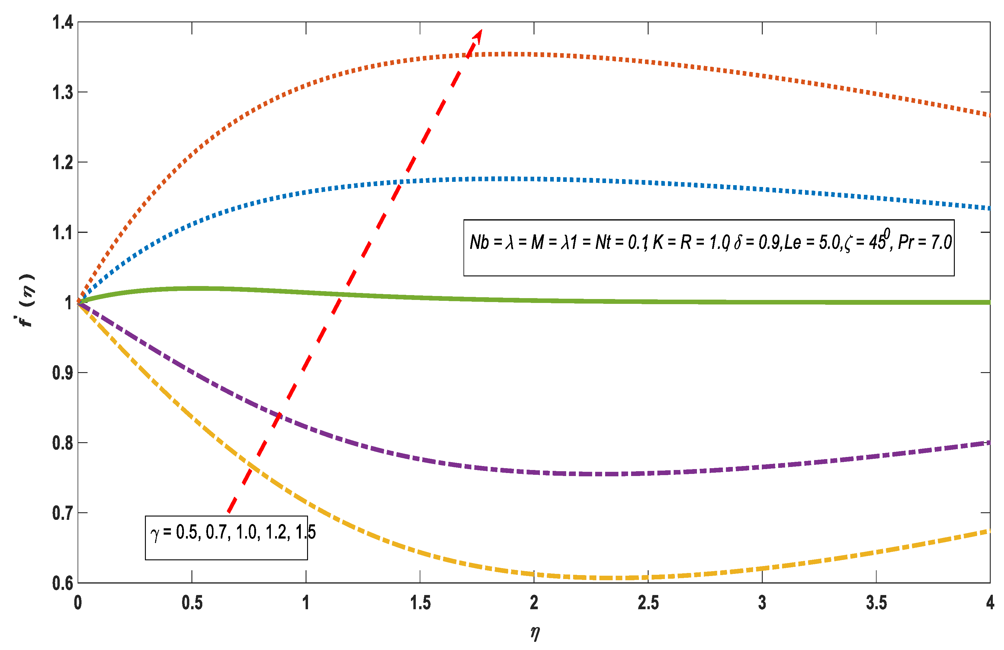
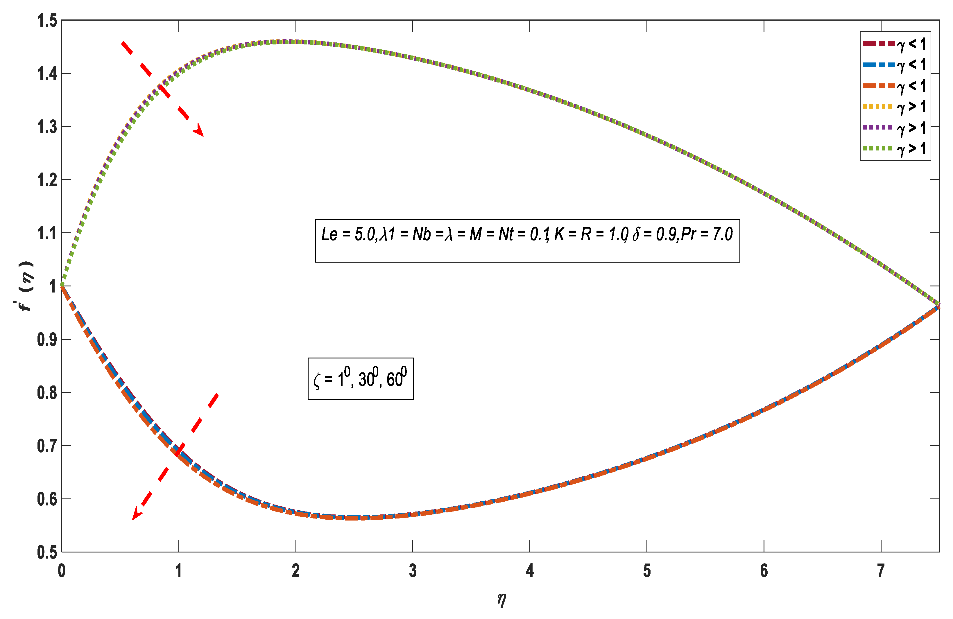
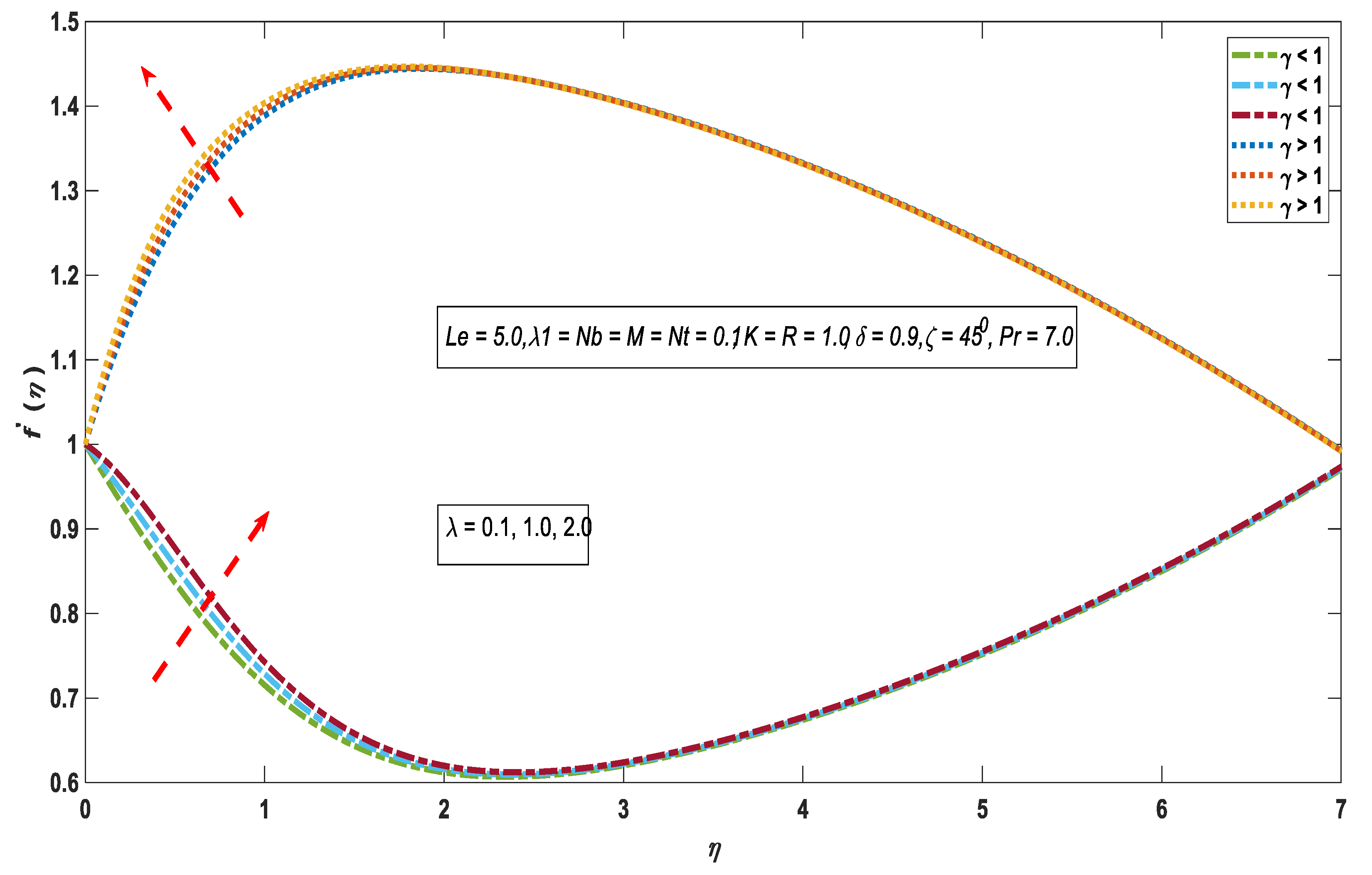
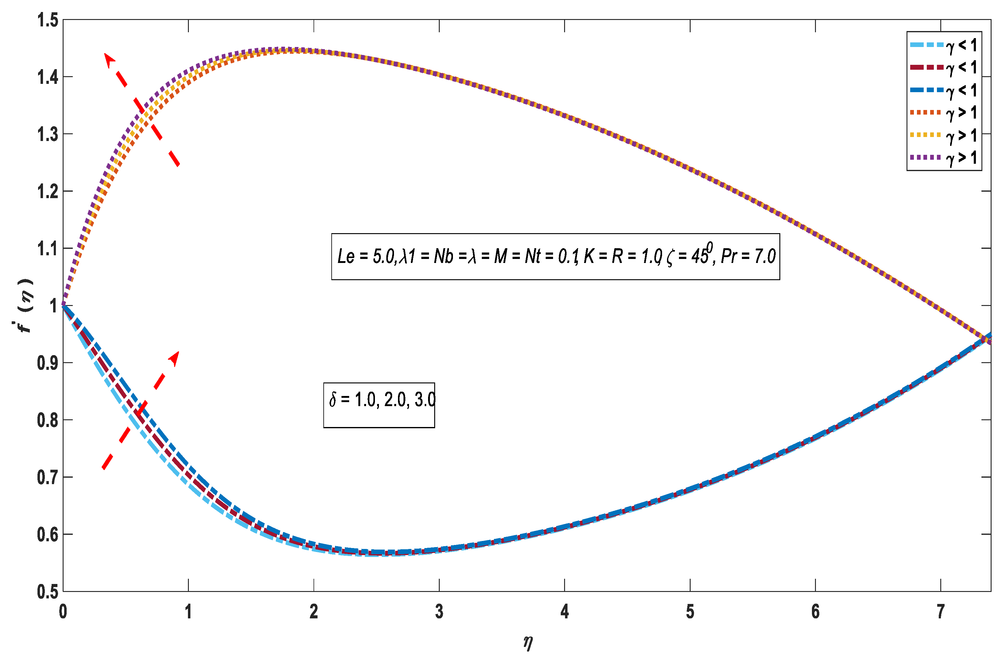
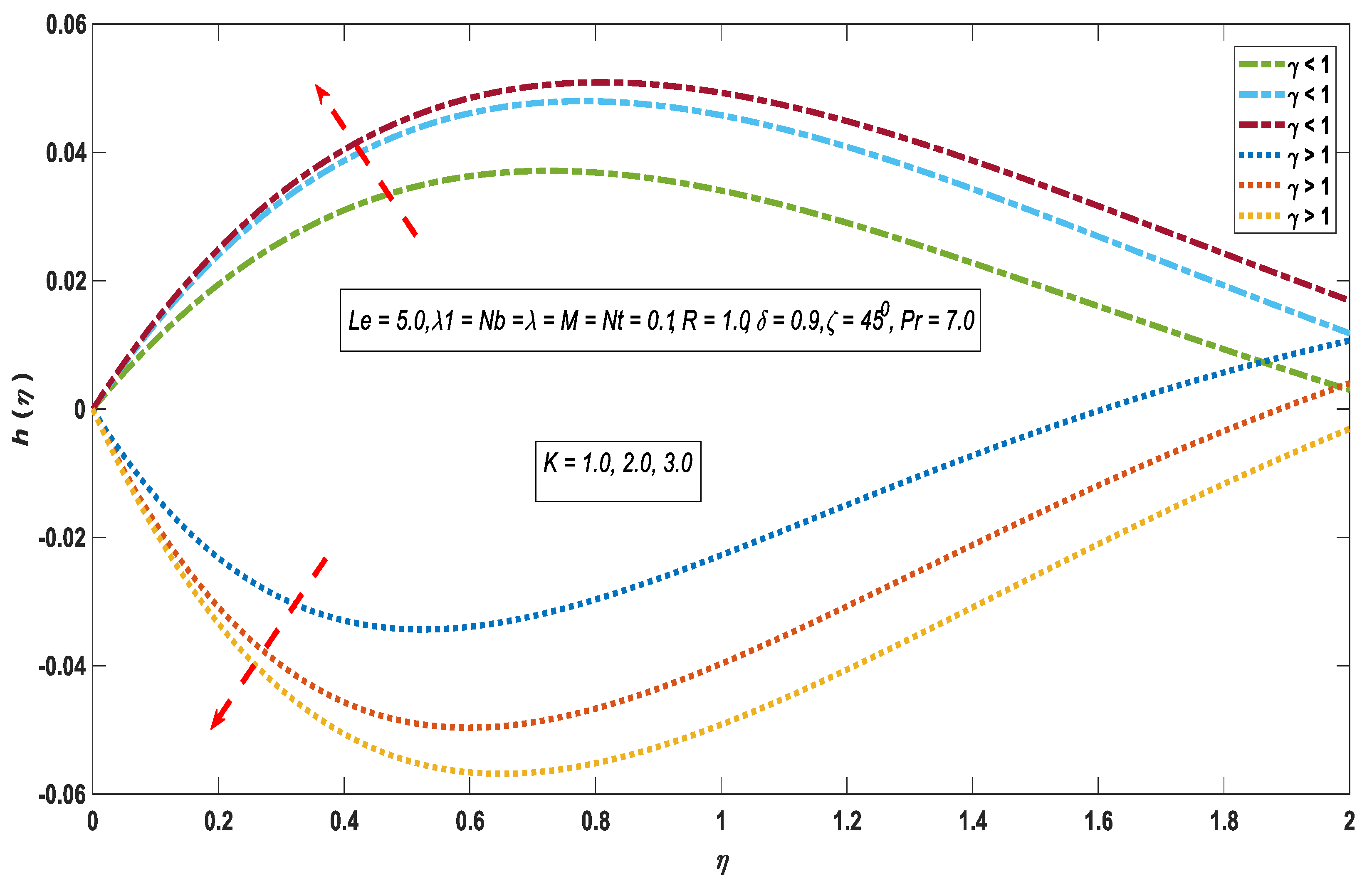
3.1. Velocity Profile

The behavior of the velocity field corresponding to the involved impacts are portrayed in Figure 1, Figure 2, Figure 3, Figure 4, Figure 5, Figure 6 and Figure 7. For the magnetic field effect on the velocity profile for γ < 1 and γ > 1 see Figure 1. It demonstrates that f ( η ) (dimensionless velocity profile) reduces for γ < 1 on improving the magnetic field strength and increases in the case of γ > 1 . Moreover, f ( η ) enhances with the growth of γ for both γ < 1 and γ > 1 shown in Figure 2. The reason behind this is when γ > 1 i.e., the free stream velocity greater than the stretching velocity, the flow develops a boundary layer. Physically, the fluid motion enhances near the stagnation point due to which the acceleration of the external stream increases, and in return, the boundary layer thickness declines with the enhancement of γ . On the other hand, when the stream velocity is less than the stretching velocity i.e., γ < 1 , the reversed boundary layer develops, but no boundary layer develops with γ = 1 because in this circumstance, both velocities are equal. Figure 3 reveals the inclination impact on velocity. It demonstrated that f ( η ) decreases on increasing the inclination. Physically, the strength of the buoyancy force reduces at ζ = 90 0 , leading to the decline in the velocity outline.
The velocity outline displays a direct relation with the buoyancy force, see Figure 4. Similarly, in Figure 5, f ( η ) follows the same pattern on the growth of the solutal buoyancy parameter as the buoyancy force impact in Figure 4. The effect of the magnetic field impact on h ( η ) is presented in Figure 6. The angular velocity upturns when γ < 1 whereas, it reduces in the case of γ > 1 for a growing magnetic field effect. Figure 7 demonstrates the effect of the material factor on the angular velocity against γ < 1 and γ > 1 . It is found that the angular velocity for the altered values of K against γ < 1 increases but shows an inverse correspondence in the case γ > 1 for growing the magnitude of K .

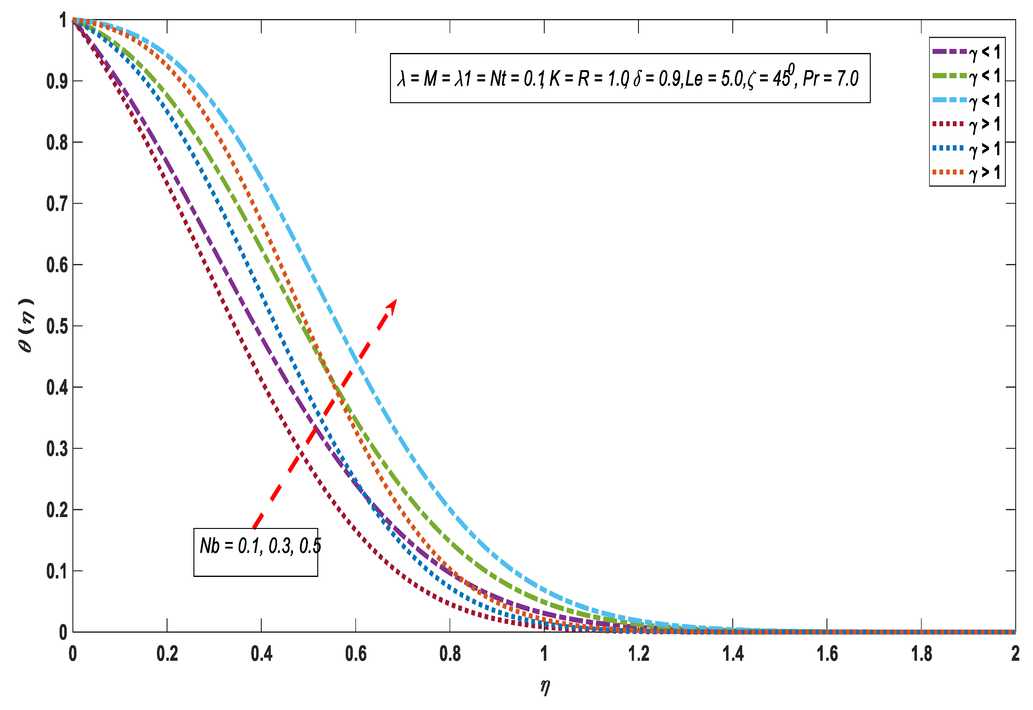
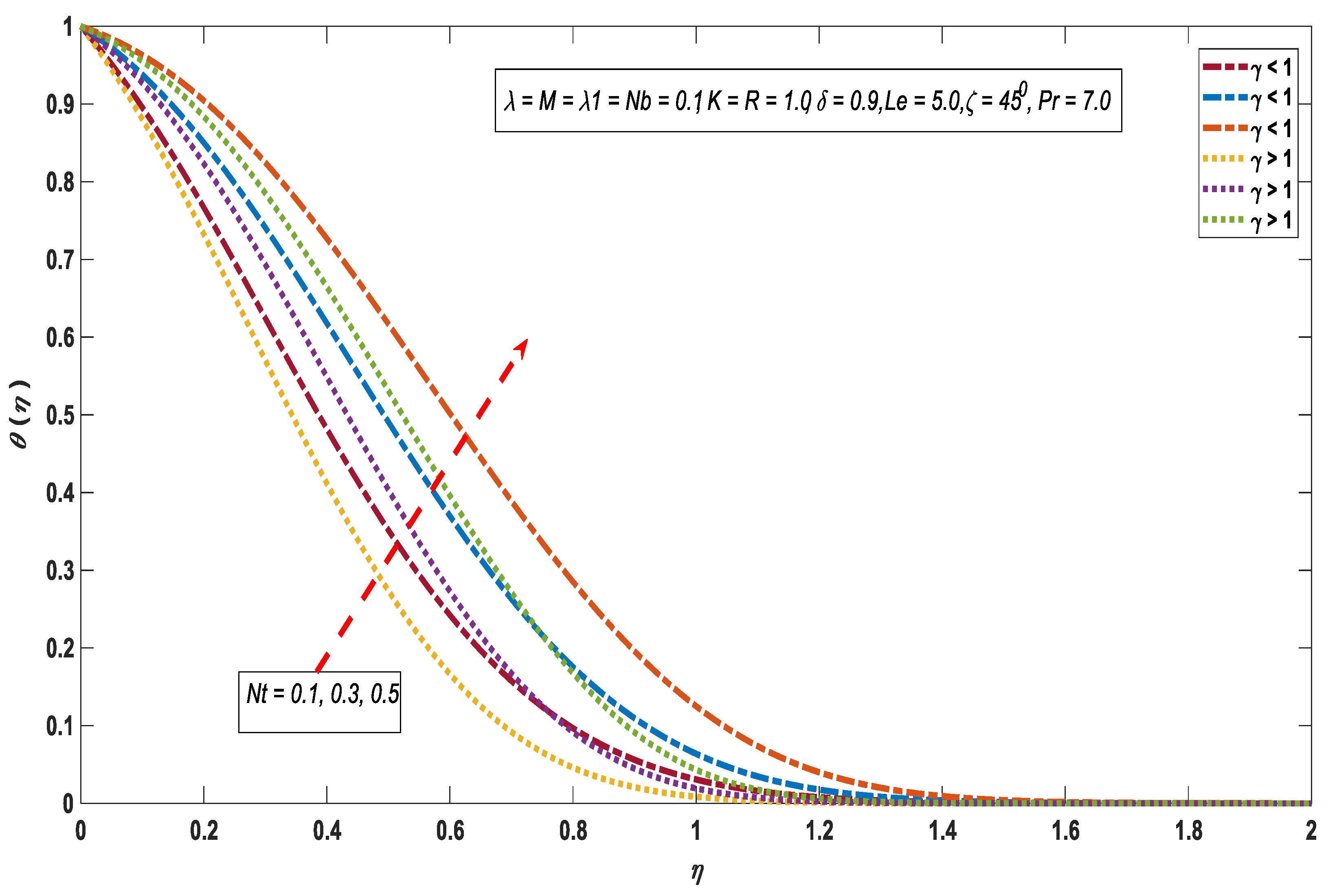
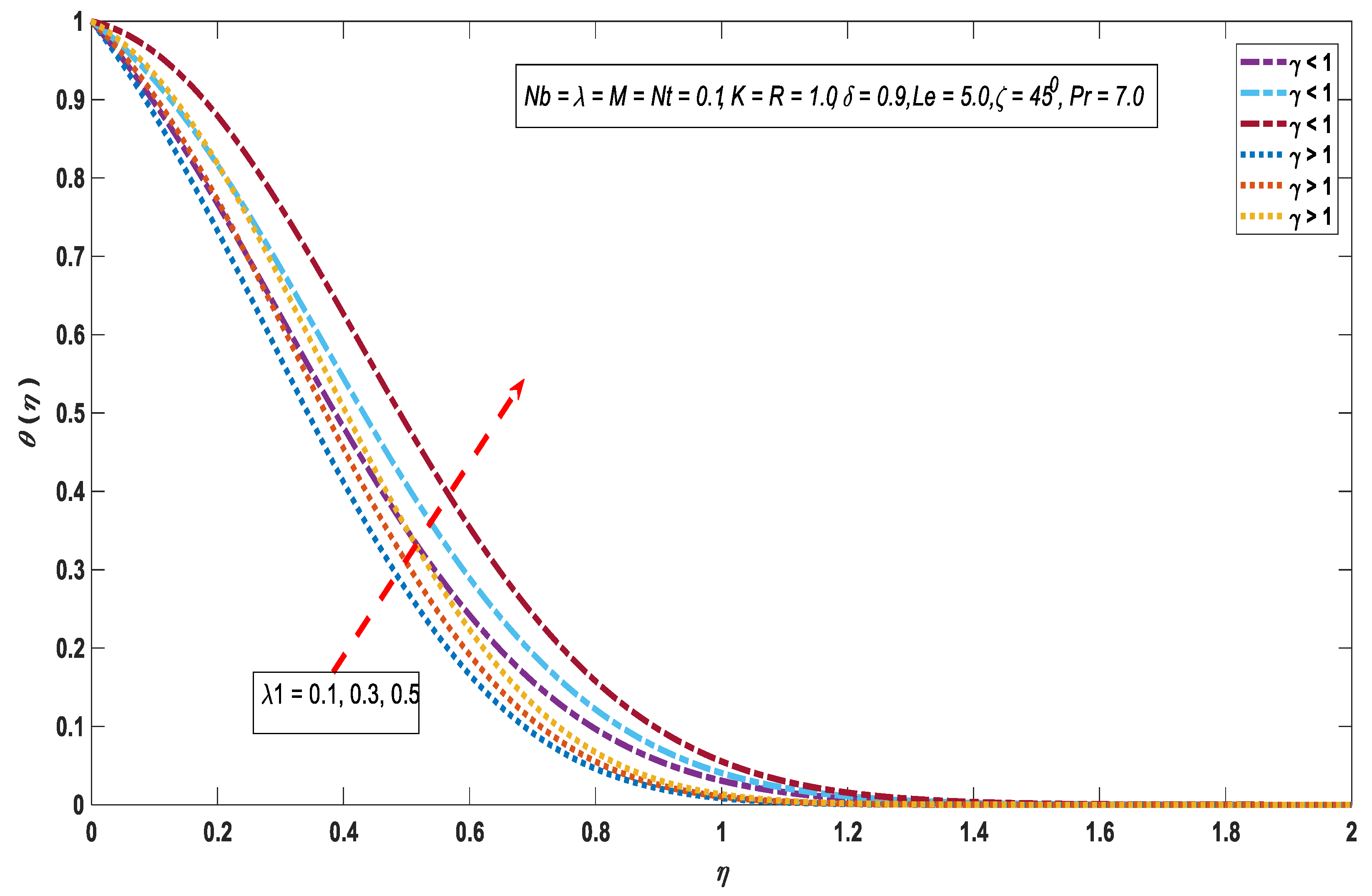
3.2. Temperature Profile

Figure 8, Figure 9 and Figure 10 exhibit the behavior of the temperature profile via altered values of incorporated factors. For the effect of the Brownian motion factor on the temperature profile for γ < 1 and γ > 1 drawn, see Figure 8. The temperature profile increases against the higher values of N b because Brownian motion is the irregular movement of the particles, which warm up the boundary layer in return and boost the temperature of the fluid. Thermophoretic impacts on the temperature profile against γ < 1 and γ > 1 are presented in Figure 9. The thermophoresis effect shows a direct relation with the temperature field because the variation in reference temperature and wall temperature improved on the growth of the thermophoretic impacts. Figure 10 demonstrates the behavior of temperature profile corresponds λ 1 . Temperature profile increases with the enhancement in the heat generation factor; because of this, the heat generates in the flow field, and in return, the temperature enhances within the thermal boundary layer.

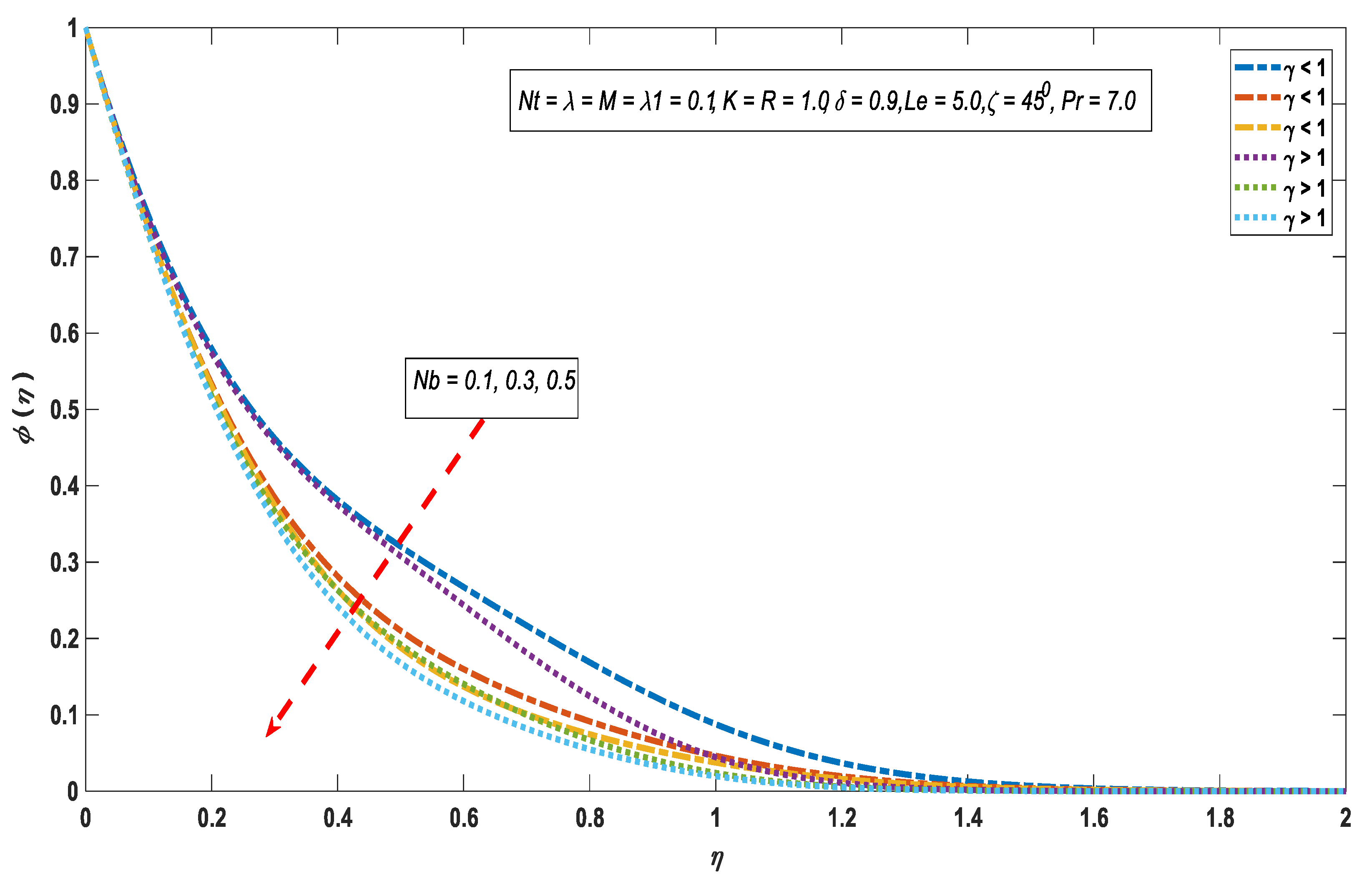
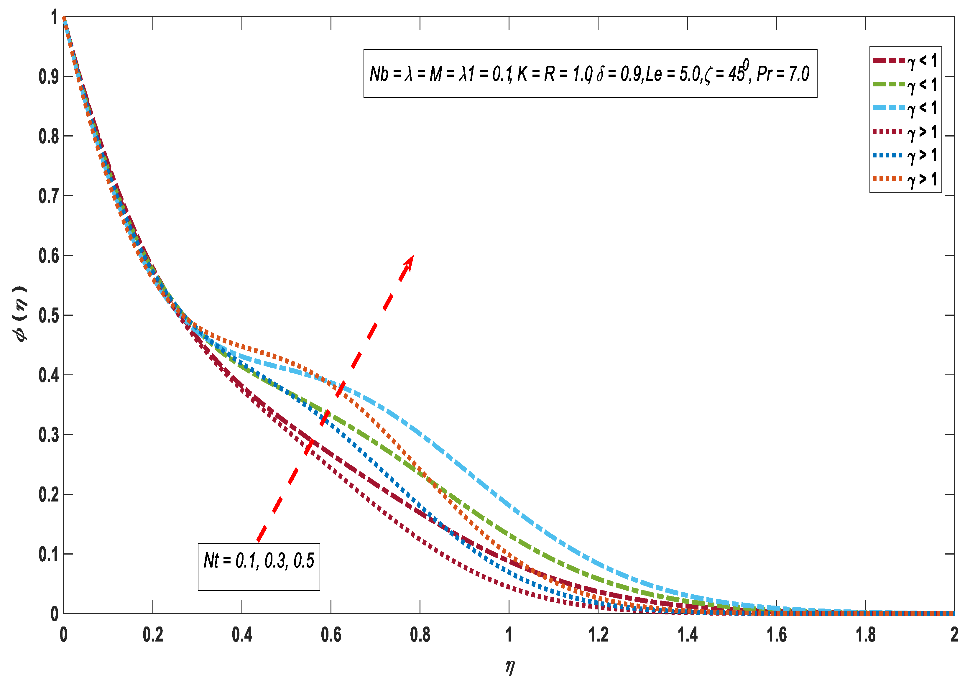
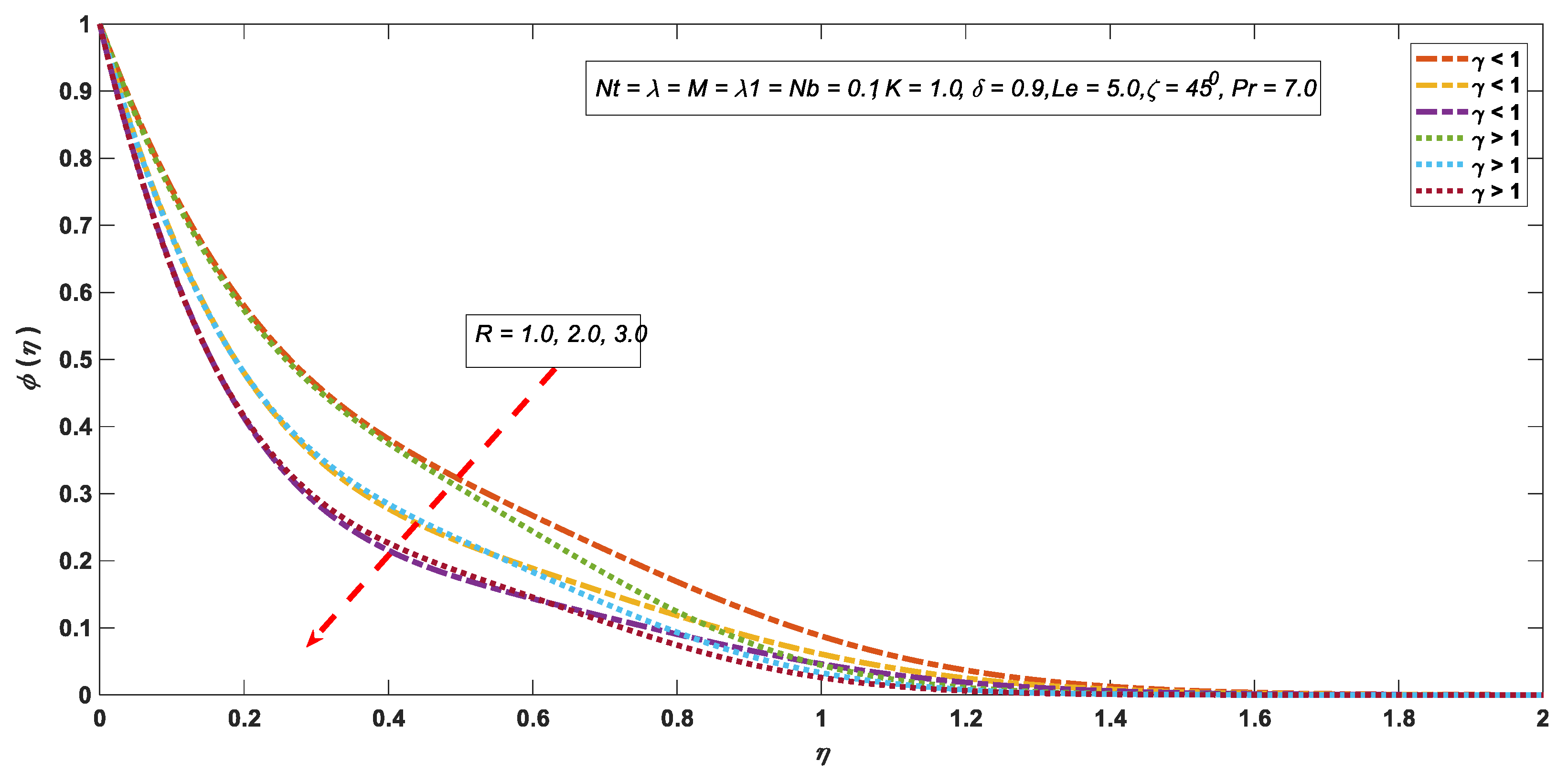
3.3. Concentration Profile

Figure 11, Figure 12 and Figure 13 signify the performance of the concentration profiles with under concerned parameters. An enhancement in N b against γ < 1 and γ > 1 decline the boundary layer thickness, which leads to a reduction in concentration profile (see Figure 11). Figure 12 specifies the thermophoretic effect on ϕ ( η ) by considering γ < 1 and γ > 1 . It is found from the sketch portrayed against the concentration for altered values of N t reduced. In sum, the concentration field against altered magnitudes of R , i.e. chemical reaction parameter, is portrayed in Figure 13. This figure discerned that ϕ ( η ) shows a reverse relation with R. Noteworthy, with the increment in the chemical reaction factor, the boundary layer thickness, as well as concentration profile, diminishes.

4. Conclusions

Heat and mass exchange of micropolar nanofluid flow adjacent to the stagnation point with magnetic effects as well as chemical reaction and heat generation or absorption reported in this article. This article fills the gap of the flow of micropolar nanofluid generated by the linear stretching inclined sheet, which plays a vital role in the heat transfer processes in industry and cooling systems. The primary outcomes of this study are as follows:
Energy and mass exchange enhance with the growth of the stagnation parameter.
The chemical reaction diminishes the concentration field with higher values.
The stagnation parameter shows direct correspondence with the velocity profile.
The heat generation or absorption factor declines the energy transport rate, whereas it improves the mass flux rate.
The velocity profile shows an opposite behavior for γ < 1 , and γ > 1 .
The velocity profile shows direct relation against growing magnitudes of bouncy impacts for γ < 1 , and γ > 1 .
This study can be utilized in the building envelop applications because of the heat transfer.

Author Contributions

Formulation done by K.R. and M.M. Problem solved by K.R. and M.I.A. Results computed by K.R.; I.K. and A.H.S. Results discussed by K.R.; E.-S.M.S. and K.S.N. All authors contributed equally in writing manuscript.

Funding

This research was funded by Researchers Supporting Project number (RSP-2019/33), King Saud University, Riyadh, Saudi Arabia.

Acknowledgments

Researchers Supporting Project number (RSP-2019/33), King Saud University, Riyadh, Saudi Arabia.

Conflicts of Interest

The authors declare no conflict of interest.

Abbreviations Table

C Fluid Concentration R Dimensionless Reaction Rate λ 1 Heat Generation Parameter
C f Skin friction coefficient R Chemical reaction parameter Re x Reynolds number
C Ambient nanoparticle volume fraction L e Lewis number S h Sherwood number
C w Surface volume fraction N b Brownian motion parameter T Fluid temperature
c p Specific heat at constant pressure N t Thermophoretic parameter T w Wall temperature
D B Brownian diffusion coefficient N u Nusselt number T Ambient temperature
D T Thermophoretic diffusion coefficient Pr Prandtle number U Composite velocity
f Similarity function for velocity Q 0 Dimensionless heat generation U Wall velocity
ρ c p Volume heat capacity μ Kinematic viscosity ν Dynamic viscosity
ϕ Dimensionless solid volume fraction w Condition at the wall Ambient condition
δ Solutal buoyancy parameter β t Thermal expansion coefficient β c Concentration expansion coefficient
σ Electric conductivity γ Spin gradient viscosity k 1 Vertex viscosity
j Micro inertia per unit mass ζ Inclination parameter Differentiation with respect to η
u Velocity in x direction v Velocity in y direction x Cartesian coordinate
θ Dimensionless temperature γ Velocity ratio parameter k Thermal conductivity
ρ Fluid density λ Bouncy parameter B 0 Uniform magnetic field strength
K Material parameter η Similarity independent variable α Thermal diffusivity
N Non-dimensional angular velocity g Gravitational acceleration θ ( 0 ) Reduced Nusselt number
ϕ ( 0 ) Reduced Sherwood number

References

  1. Mishra, S.; Khan, I.; Al-Mdallal, Q.; Asifa, T. Free convective micropolar fluid flow and heat transfer over a shrinking sheet with heat source. Case Stud. Therm. Eng. 2018, 11, 113–119. [Google Scholar] [CrossRef]
  2. Salleh, M.Z.; Rohni, A.M.; Amin, N. Boundary Layer Flow Due to a Moving Flat Plate in Micropolar Fluid. J. Teknol. 2005, 43, 67–83. [Google Scholar] [CrossRef]
  3. Eringen, A.C. Simple microfluids. Int. J. Eng. Sci. 1964, 2, 205–217. [Google Scholar] [CrossRef]
  4. Rahman, M.M.; Aziz, A.; Al-Lawatia, M.A. Heat transfer in micropolar fluid along an inclined permeable plate with variable fluid properties. Int. J. Therm. Sci. 2010, 49, 993–1002. [Google Scholar] [CrossRef]
  5. Uddin, M.J. Convective Flow of Micropolar Fluids along an Inclined Flat Plate with Variable Electric Conductivity and Uniform Surface Heat Flux. Daffodil Int. Univ. J. Sci. Technol. 2011, 6, 69–79. [Google Scholar] [CrossRef]
  6. Md, S.; Thumma, T.; Shamshuddin, M. Numerical study of a dissipative micropolar fluid flow past an inclined porous plate with heat source/sink. Propuls. Power Res. 2019, 8, 56–68. [Google Scholar] [CrossRef]
  7. Rafique, K.; Anwar, M.I.; Misiran, M. Numerical Study on Micropolar Nanofluid Flow over an Inclined Surface by Means of Keller-Box. Asian J. Probab. Stat. 2019, 4, 1–21. [Google Scholar] [CrossRef]
  8. Ali, V.; Gul, T.; Afridi, S.; Ali, F.; Alharbi, S.O.; Khan, I. Thin Film Flow of Micropolar Fluid in a Permeable Medium. Coatings 2019, 9, 98. [Google Scholar] [CrossRef]
  9. Matta, A.; Gajjela, N. Order of chemical reaction and convective boundary condition effects on micropolar fluid flow over a stretching sheet. AIP Adv. 2018, 8, 115212. [Google Scholar] [CrossRef] [Green Version]
  10. Jaiswal, S.; Yadav, P.K. A micropolar-Newtonian blood flow model through a porous layered artery in the presence of a magnetic field. Phys. Fluids 2019, 31, 071901. [Google Scholar] [CrossRef]
  11. Rauf, A.; Shehzad, S.A.; Abbas, Z.; Hayat, T. Unsteady three-dimensional MHD flow of the micropolar fluid over an oscillatory disk with Cattaneo-Christov double diffusion. Appl. Math. Mech. 2019, 40, 1471–1486. [Google Scholar] [CrossRef]
  12. Soid, S.K.; Ishak, A.; Pop, I. MHD Stagnation-Point Flow over a Stretching/Shrinking Sheet in a Micropolar Fluid with a Slip Boundary. Sains Malays. 2018, 47, 2907–2916. [Google Scholar] [CrossRef]
  13. Xiao, B.; Wang, W.; Zhang, X.; Long, G.; Fan, J.; Chen, H.; Deng, L. A novel fractal solution for permeability and Kozeny-Carman constant of fibrous porous media made up of solid particles and porous fibers. Powder Technol. 2019, 349, 92–98. [Google Scholar] [CrossRef]
  14. Duncan, T.V. Applications of nanotechnology in food packaging and food safety: Barrier materials, antimicrobials and sensors. J. Colloid Interface Sci. 2011, 363, 1–24. [Google Scholar] [CrossRef]
  15. Qu, X.; Alvarez, P.J.; Li, Q. Applications of nanotechnology in water and wastewater treatment. Water Res. 2013, 47, 3931–3946. [Google Scholar] [CrossRef]
  16. Krajnik, P.; Pusavec, F.; Rashid, A. Nanofluids: Properties, Applications and Sustainability Aspects in Materials Processing Technologies. In Advances in Sustainable Manufacturing; Springer Science and Business Media LLC: Berlin, Germany, 2011; pp. 107–113. [Google Scholar]
  17. Choi, S.U.; Eastman, J.A. Enhancing Thermal Conductivity of Fluids with Nanoparticles; No. ANL/MSD/CP-84938; CONF-951135-29; Argonne National Lab.: DuPage, IL, USA, 1995. [Google Scholar]
  18. Abbas, Z.; Hasnain, J.; Sajid, M. Effects of Slip on MHD Flow of a Dusty Fluid over a Stretching Sheet through Porous Space. J. Eng. Thermophys. 2019, 28, 84–102. [Google Scholar] [CrossRef]
  19. Sakiadis, B.C. Boundary-layer behavior on continuous solid surfaces: I. Boundary-layer equations for two-dimensional and axisymmetric flow. AIChE J. 1961, 7, 26–28. [Google Scholar] [CrossRef]
  20. Crane, L.J. Flow past a stretching plate. Z. Angew. Math. Phys. ZAMP 1970, 21, 645–647. [Google Scholar] [CrossRef]
  21. Ali, M.; Alim, M.A.; Alam, M.S. Heat transfer boundary layer flow past an inclined stretching sheet in the presence of magnetic field. Int. J. Adv. Res. Technol. 2014, 3, 34–40. [Google Scholar]
  22. Khan, I.; Shafquatullah; Malik, M.; Hussain, A.; Khan, M. Magnetohydrodynamics Carreau nanofluid flow over an inclined convective heated stretching cylinder with Joule heating. Results Phys. 2017, 7, 4001–4012. [Google Scholar] [CrossRef]
  23. Rashad, A.M. Unsteady nanofluid flow over an inclined stretching surface with convective boundary condition and anisotropic slip impact. Int. J. Heat Technol. 2017, 35, 82–90. [Google Scholar] [CrossRef]
  24. Reddy, P.B.A.; Bareddy, P. Magnetohydrodynamic flow of a Casson fluid over an exponentially inclined permeable stretching surface with thermal radiation and chemical reaction. Ain Shams Eng. J. 2016, 7, 593–602. [Google Scholar] [CrossRef] [Green Version]
  25. Samanta, A. Effect of electric field on an oscillatory film flow. Phys. Fluids 2019, 31, 034109. [Google Scholar] [CrossRef]
  26. Ramreddy, C.; Naveen, P.; Srinivasacharya, D. Department of Mathematics National Institute of Technology Warangal-; India Quadratic Convective Flow of a Micropolar Fluid along an Inclined Plate in a Non-Darcy Porous Medium with Convective Boundary Condition. Nonlinear Eng. 2017, 6, 139–151. [Google Scholar] [CrossRef]
  27. Hayat, T.; Asad, S.; Mustafa, M.; Alsaedi, A. Radiation Effects on the Flow of Powell-Eyring Fluid Past an Unsteady Inclined Stretching Sheet with Non-Uniform Heat Source/Sink. PLoS ONE 2014, 9, e103214. [Google Scholar] [CrossRef]
  28. Hiemenz, K. Die Grenzschicht an einem in den gleichformigen Flussigkeitsstrom eingetauchten geraden Kreiszylinder. Dinglers Polytech. J. 1911, 326, 321–324. [Google Scholar]
  29. Gupta, S.; Kumar, D.; Singh, J. MHD mixed convective stagnation point flow and heat transfer of an incompressible nanofluid over an inclined stretching sheet with chemical reaction and radiation. Int. J. Heat Mass Transf. 2018, 118, 378–387. [Google Scholar] [CrossRef]
  30. Rehman, F.U.; Nadeem, S.; Rehman, H.U.; Haq, R.U. Thermophysical analysis for three-dimensional MHD stagnation-point flow of nano-material influenced by an exponential stretching surface. Results Phys. 2018, 8, 316–323. [Google Scholar] [CrossRef]
  31. Anwar, M.I.; Shafie, S.; Hayat, T.; Shehzad, S.A.; Salleh, M.Z. Numerical study for MHD stagnation-point flow of a micropolar nanofluid towards a stretching sheet. J. Braz. Soc. Mech. Sci. Eng. 2017, 39, 89–100. [Google Scholar] [CrossRef]
  32. Dholey, S. Unsteady separated stagnation-point flow over a permeable surface. Z. Angew. Math. Phys. 2019, 70, 10. [Google Scholar] [CrossRef]
  33. Kamal, F.; Zaimi, K.; Ishak, A.; Pop, I. Stability Analysis of MHD Stagnation-point Flow towards a Permeable Stretching/Shrinking Sheet in a Nanofluid with Chemical Reactions Effect. Sains Malays. 2019, 48, 243–250. [Google Scholar] [CrossRef]
  34. Ghasemian, A.; Dinarvand, S.; Adamian, A.; Sheremet, M.A. Unsteady General Three-Dimensional Stagnation Point Flow of a Maxwell/Buongiorno Non-Newtonian Nanofluid. J. Nanofluids 2019, 8, 1544–1559. [Google Scholar] [CrossRef]
  35. Nadeem, S.; Khan, M.R.; Khan, A.U. MHD oblique stagnation point flow of nanofluid over an oscillatory stretching/shrinking sheet: Existence of dual solutions. Phys. Scr. 2019, 94, 075204. [Google Scholar] [CrossRef]
  36. Vasanthakumari, R.; Pondy, P. Mixed convection of silver and titanium dioxide nanofluids along inclined stretching sheet in presence of MHD with heat generation and suction effect. Math. Model. Eng. Probl. 2018, 5, 123–129. [Google Scholar] [CrossRef]
  37. Saeed, A.; Shah, Z.; Islam, S.; Jawad, M.; Ullah, A.; Gul, T.; Kumam, P. Three-Dimensional Casson Nanofluid Thin Film Flow over an Inclined Rotating Disk with the Impact of Heat Generation/Consumption and Thermal Radiation. Coatings 2019, 9, 248. [Google Scholar] [CrossRef]
  38. Elgazery, N.S. Nanofluids flow over a permeable unsteady stretching surface with non-uniform heat source/sink in the presence of inclined magnetic field. J. Egypt. Math. Soc. 2019, 27, 9. [Google Scholar]
  39. Mjankwi, M.A.; Masanja, V.G.; Mureithi, E.W.; James, M.N. Unsteady MHD Flow of Nanofluid with Variable Properties over a Stretching Sheet in the Presence of Thermal Radiation and Chemical Reaction. Int. J. Math. Math. Sci. 2019, 2019, 1–14. [Google Scholar] [CrossRef]
  40. Rafique, K.; Anwar, M.I.; Misiran, M. Keller-box Study on Casson Nano Fluid Flow over a Slanted Permeable Surface with Chemical Reaction. Asian Res. J. Math. 2019, 14, 1–17. [Google Scholar] [CrossRef]
  41. Mishra, A.; Kumar, M. Ohmic–Viscous Dissipation and Heat Generation/Absorption Effects on MHD Nanofluid Flow Over a Stretching Cylinder with Suction/Injection. In Advanced Computing and Communication Technologies; Springer: Singapore, 2019; pp. 45–55. [Google Scholar]
  42. Khan, W.; Pop, I.; Khan, W. Boundary-layer flow of a nanofluid past a stretching sheet. Int. J. Heat Mass Transf. 2010, 53, 2477–2483. [Google Scholar] [CrossRef]
Figure 1. Velocity profile for M .
Symmetry 11 01379 g001
Figure 2. Velocity profile for γ .
Symmetry 11 01379 g002
Figure 3. Velocity profile for ζ .
Symmetry 11 01379 g003
Figure 4. Velocity profile for λ .
Symmetry 11 01379 g004
Figure 5. Velocity profile for δ .
Symmetry 11 01379 g005
Figure 6. Angular velocity profile for M .
Symmetry 11 01379 g006
Figure 7. Angular velocity for K .
Symmetry 11 01379 g007
Figure 8. Temperature profile for N b .
Symmetry 11 01379 g008
Figure 9. Temperature profile for N t .
Symmetry 11 01379 g009
Figure 10. Temperature profile for λ 1 .
Symmetry 11 01379 g010
Figure 11. Concentration profile for N b .
Symmetry 11 01379 g011
Figure 12. Concentration profile for N t .
Symmetry 11 01379 g012
Figure 13. Concentration profile for R .
Symmetry 11 01379 g013
Table 1. Contrast of θ ( 0 ) and ϕ ( 0 ) against M , R , λ 1 , γ , λ , δ = 0 with L e , Pr = 10 and ζ = 90 0 .
N b N t Khan and Pop [42]Present Results
θ ( 0 ) ϕ ( 0 ) θ ( 0 ) ϕ ( 0 )
0.10.10.95242.12940.95242.1294
0.20.20.36542.51520.36542.5152
0.30.30.13552.60880.13552.6088
0.40.40.04952.60380.04952.6038
0.50.50.01792.57310.01792.5731
Table 2. Values of θ ( 0 ) , ϕ ( 0 ) and C f x ( 0 ) .
N b N t Pr L e M K R λ 1 λ δ γ ζ θ ( 0 ) ϕ ( 0 ) C f x ( 0 )
0.10.17.05.00.11.01.00.10.10.90.54500.89662.85630.6967
0.50.17.05.00.11.01.00.10.10.90.54500.06402.88060.7234
0.10.37.05.00.11.01.00.10.10.90.54500.49313.68090.6509
0.10.110.05.00.11.01.00.10.10.90.54500.83222.97410.6955
0.10.17.010.00.11.01.00.10.10.90.54500.81004.16610.7506
0.10.17.05.00.51.01.00.10.10.90.54500.88852.85240.8200
0.10.17.05.00.13.01.00.10.10.90.54500.91202.86420.9514
0.10.17.05.00.11.03.00.10.10.90.54500.81224.49440.7482
0.10.17.05.00.11.01.00.50.10.90.54500.18903.34360.7051
0.10.17.05.00.11.01.00.10.50.90.54500.90072.85790.6064
0.10.17.05.00.11.01.00.10.12.00.54500.90712.86070.4742
0.10.17.05.00.11.01.00.10.10.91.54501.02432.9339−1.4412
0.10.17.05.00.11.01.00.10.10.90.56000.89372.85520.7570
0.10.17.05.00.11.01.00.10.10.90.59000.88672.85230.9033

