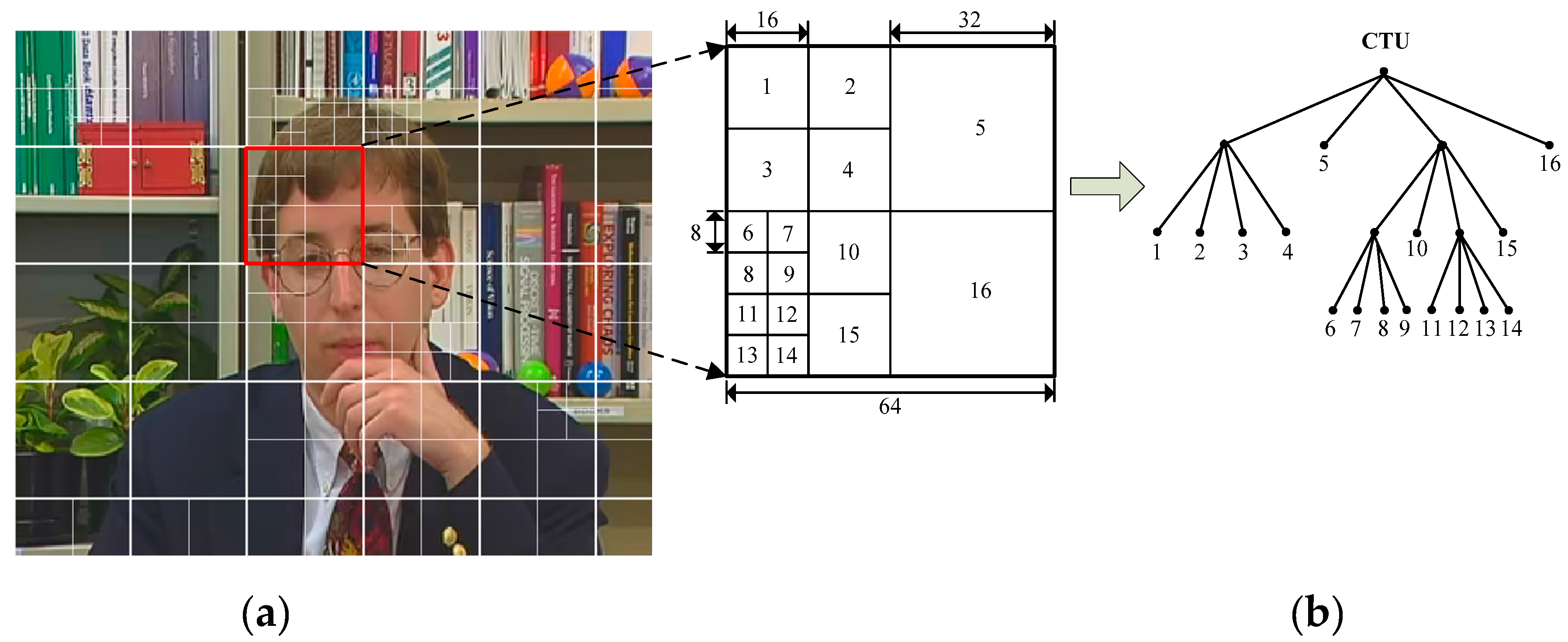
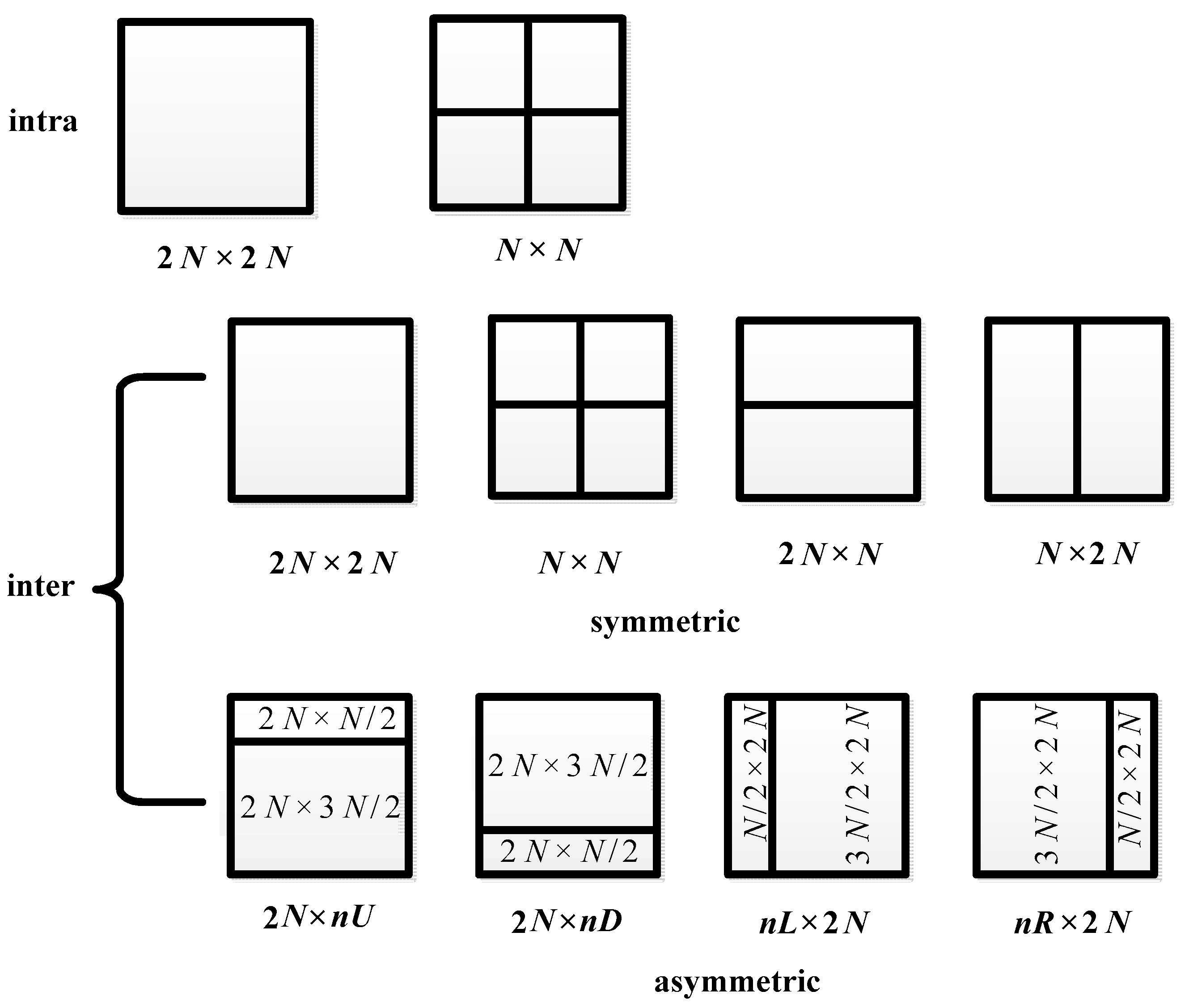
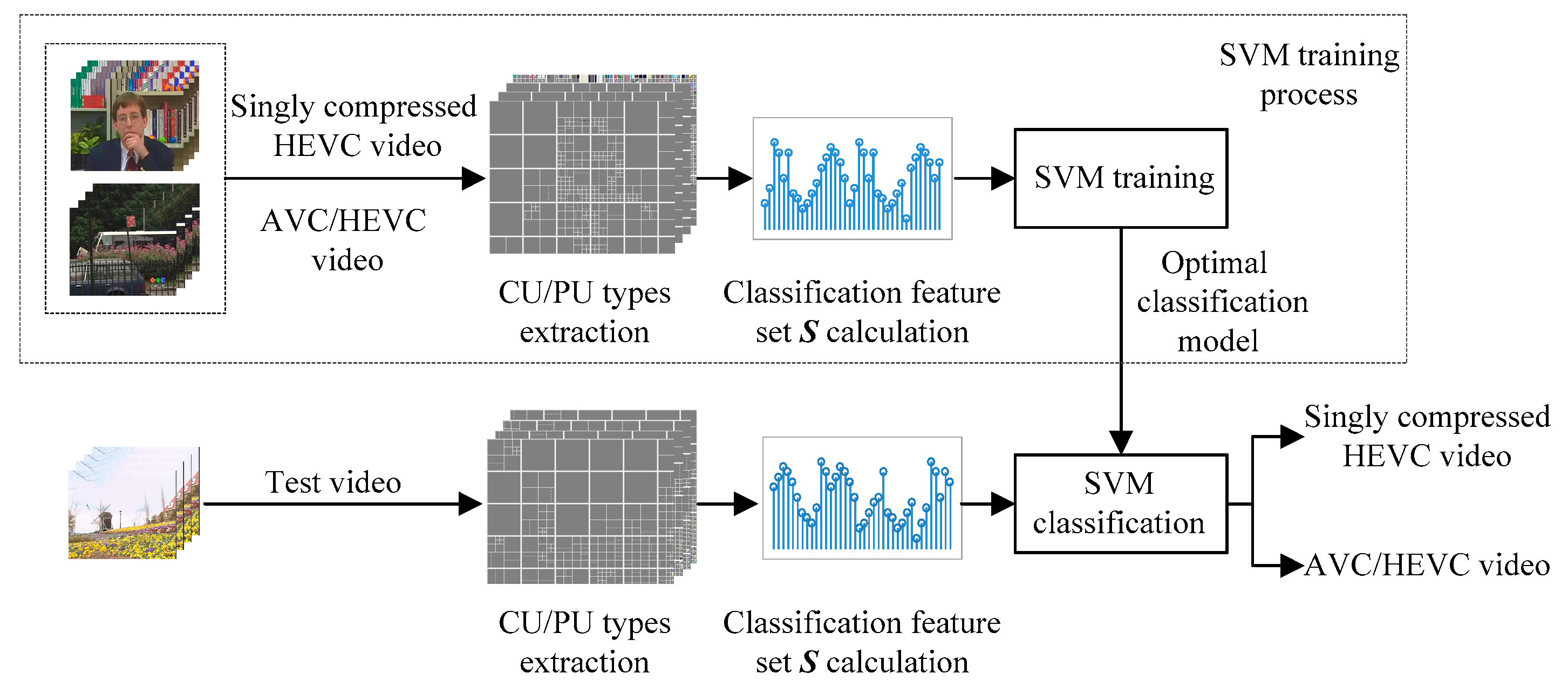
In the AVC and HEVC encoding process, quantization and reconstruction are basic operations, but they will introduce irreversible quantization errors and reconstruction errors, which make the decoded video different from the original one. The change of video content will further affect the CU and PU partition types and makes them different between AVC/HEVC videos and singly compressed HEVC videos. We will illustrate the difference elaborately in this section.
3.1. Theoretical Analysis
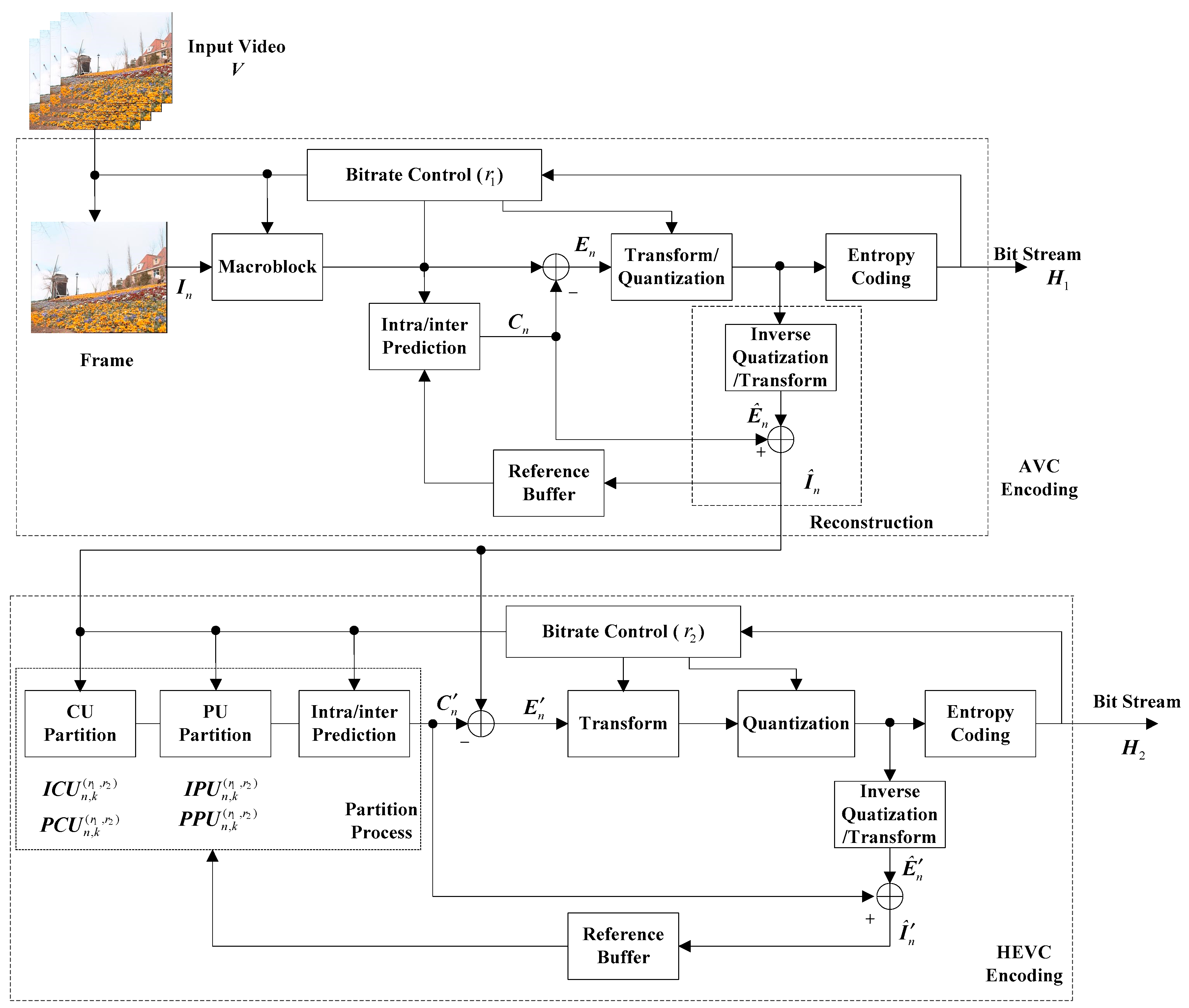
Figure 4 describes the simplified block diagram of AVC/HEVC transcoding. YUV video is a kind of uncompressed video and often used as test example of video encoders. Given a YUV video
V, the first step is to encode
V into the AVC bit stream
with bitrate
. Then
will be decoded to YUV video
and recompressed into the HEVC bit stream
with bitrate
. Please note two points here. One is that the reconstruction module in the encoding process is equivalent to the decoding process; thus we directly use the reconstruction module to represent the decoder in
Figure 4 to save space. The other one is that only HEVC encoding is implemented for a singly compressed HEVC video. That is to say, for a singly compressed HEVC video, the input video is the uncompressed YUV video
V, not its decoded version
.
From
Figure 4, we can see that CU and PU partition types of each picture are determined by the content of the picture and the number of bits allocated to it by the rate control module. Here, please note that in this paper, a picture contains only one slice. Though CU and PU partition types in I pictures are different from P pictures, the partition strategy is similar. Therefore, we take the CU types in P pictures as an example to analyze the difference between AVC/HEVC videos and singly compressed HEVC videos.
Now let’s consider the AVC/HEVC transcoding process. Assume one uncompressed video sequence V consists of N P pictures and is expressed as Equation (1), where denotes the nth P picture of V, then the bit stream can be obtained by implementing the prediction, transform, quantization, and entropy coding process.
In the AVC encoding process, a rate control process is implemented. Assume the bit rate for V is r, let denote the rate control process, then, the number of bits allocated to the nth P picture can be represented as . After that, the quantization step for the picture will be determined according to . In addition, AVC standard adopts macroblock as the basic coding unit and does not introduce the concept of CU; hence, CU types do not exist in the AVC encoding process.
The decoding process is the inverse process of encoding. Let stand for the prediction signal of , and represent discrete cosine transform (DCT) and inverse DCT, respectively, then the decoded video sequence can be obtained by Equations (2) and (3), where means the decoded version of , represents the rounding operator, and denote the irreversible quantization error and reconstruction error of and , respectively. The quantization error means the error introduced in the quantization process. The reconstruction error means the rounding error and truncation error generated in the reconstruction process.
In the process of transcoding to the HEVC bit stream , the number of bits are allocated to the nth P picture according to Equation (4). Here we use rather than to represent the rate control process because the bits allocation function adopted in HEVC is different from the AVC standard.
Knowing the number of bits allocated to the
nth P picture, the type of the
kth CU in the
nth P picture
can be written as Equation (5), where
stands for the CU partition process, and
denotes the corresponding prediction signal of
.
For a singly compressed HEVC video with bitrate , the number of bits allocated to the nth P picture, and the CU partition type will be determined by Equations (6) and (7).
Eventually, we can get the difference of CU partition types between the AVC/HEVC video and the singly compressed HEVC video according to Equation (8).
As shown in Equation (8), we can see that would be different from . There are two factors that lead to the difference. One is the difference between and . Equation (2) states that the irreversible quantization error and reconstruction error would make different from . Here, please note that the quantization error is closely related to . The bigger the , the bigger the quantization error. However, is determined by the number of bits allocated to the picture , which makes indirectly decided by the rate control process. Because the rate control process in AVC is quite different from HEVC, the selection of in AVC would be different from that in HEVC, which further enlarges the difference between and . The other factor that causes to be different from is the difference between and . and are the prediction signals of and , respectively, which are calculated according to the reconstruction pictures encoded before and . Since there also exists quantization error and reconstruction error in the reconstruction pictures, would be different from .
Because of the CU types in the I pictures, the PU types in I pictures and P pictures would also be inevitably affected by the quantization error, reconstruction error, and bits allocation method; the theoretical analyses of them are similar to the CU types in P pictures. Therefore, it can be concluded that the CU types in I pictures and P pictures and the PU types in I pictures and P pictures would be different between singly compressed HEVC videos and AVC/HEVC videos.
3.2. Illustrative Examples
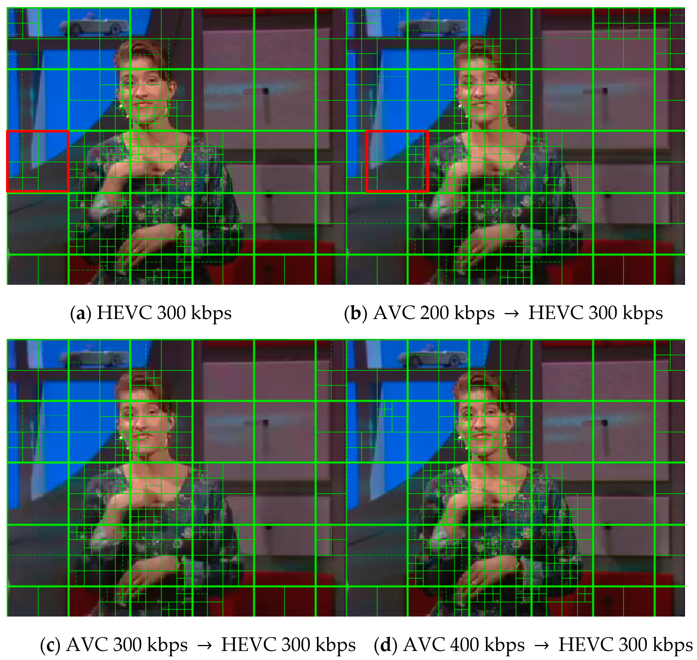
In this subsection, we will exhibit the CU and PU partition types of singly compressed HEVC videos and AVC/HEVC videos to demonstrate the difference between them. YUV sequence “sign_irene” is selected as the testing video. For singly compressed HEVC video, this YUV sequence is directly encoded with an HEVC standard at bitrate 300 Kbps, while for a transcoded HEVC video, this YUV sequence is encoded with an AVC standard at bitrate 200 Kbps, 300 Kbps, and 400 Kbps followed by an HEVC standard at bitrate 300 Kbps, respectively.
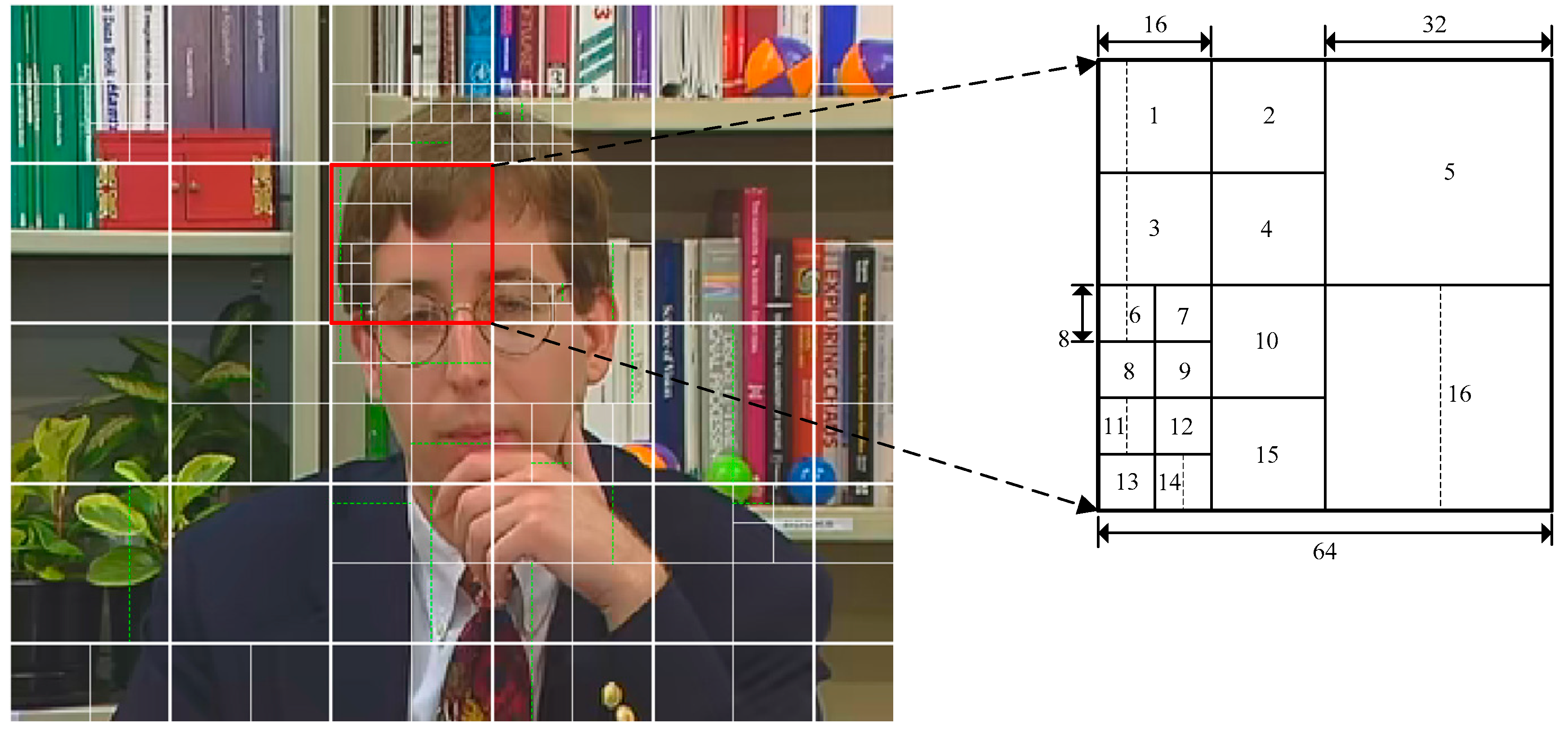
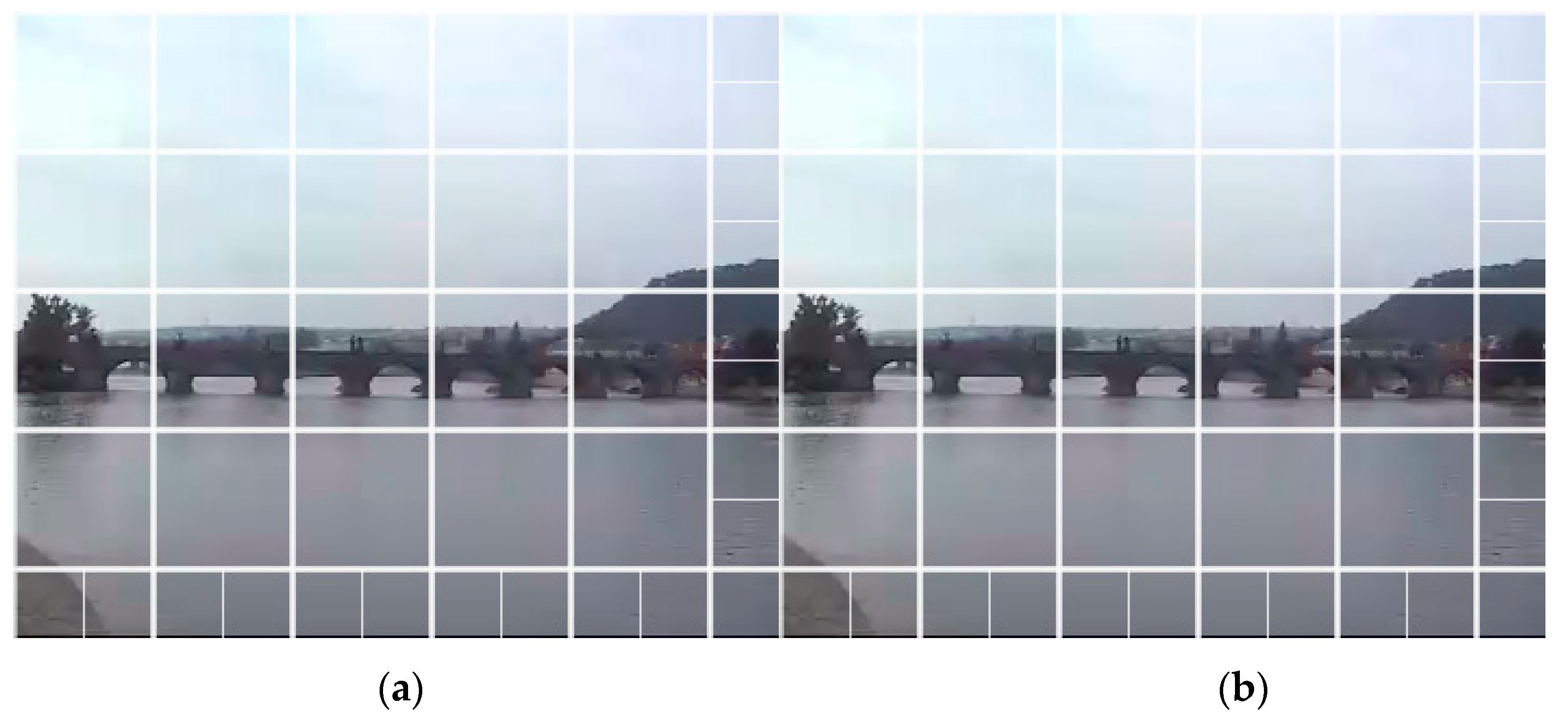
Figure 5 presents the CU and PU partition of the first P picture in the fourth GOP, where solid lines and dotted lines indicate the CU boundaries and PU boundaries, respectively.
Figure 5a shows the CU and PU partition of the singly compressed HEVC video.
Figure 5b–d show the CU and PU partition of HEVC videos transcoded from AVC videos with bitrates 200 Kbps, 300 Kbps, and 400 Kbps, respectively.
It can be observed that the CU and PU partition in AVC/HEVC transcoded picture is much different from singly compressed HEVC picture, even though they have the same visual content. This phenomenon verifies the analysis depicted in
Section 3.1, and thus, CU and PU partition types can be exploited as footprints for AVC/HEVC video detection. Furthermore, looking at the block marked by the red boundaries in
Figure 5a,b, they have the same CU partitions, but their PU partitions differ. CU usually reflects the complexity of the CTU contents, and PU can better capture the subtle differences in content. That is to say, CU types and PU types are complementary when encoding one video. The CU types and PU types in the I pictures have a similar phenomenon. Therefore, CU types and PU types can be used as complementary features, and we can merge them to detect AVC/HEVC videos.
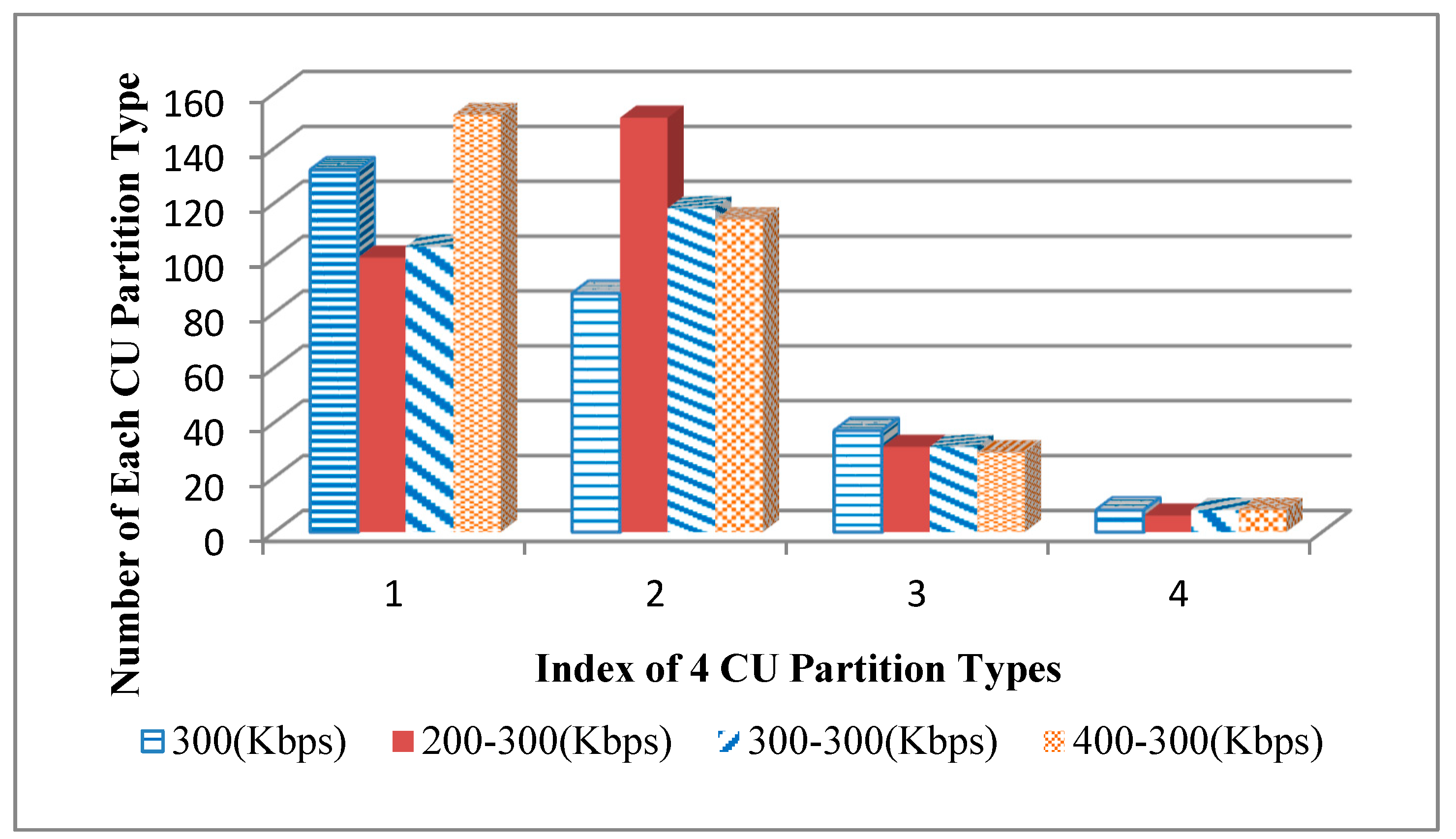
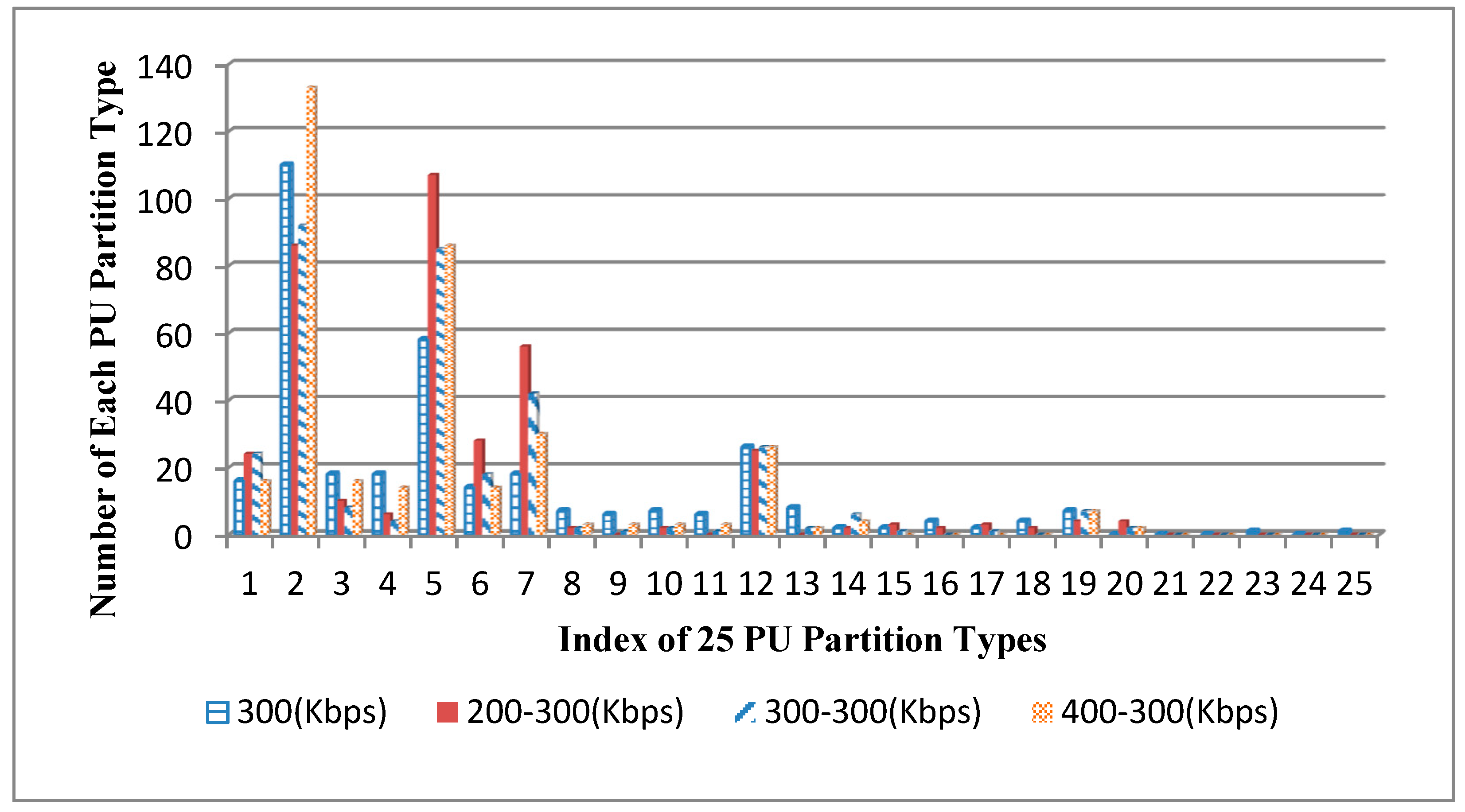
In order to illustrate the characteristics of CU and PU partitions more clearly, the numbers of each CU and PU partition type in
Figure 5 are exhibited in
Figure 6 and
Figure 7. We can see that the number of each CU and PU partition type in the AVC/HEVC video is much different from the singly compressed HEVC video. For example, for the 8×8 PU partition type, the numbers of them in 200–300 Kbps and 300–300 Kbps AVC/HEVC videos are nearly 25 and 20 smaller than that in the singly compressed HEVC video, respectively, while the number of it in the 400–300 Kbps AVC/HEVC video is much bigger than that in singly compressed HEVC video. Based on the above theoretic analysis and examples, it is reasonable to take both CU and PU types in the I pictures and P pictures as classification features and use them to identify AVC/HEVC videos with the SVM classification method. The specific feature extraction method and the classification method will be explicated in
Section 4.
