Article

Impact-Damage Equivalency for Twisted Composite Blades with Symmetrical Configurations

1
College of Civil Aviation, Nanjing University of Aeronautics and Astronautics, Nanjing 211100, China
2
Commercial Aircraft Engine Co., LTD, Aero Engine Cooperation of China, Shanghai 201100, China
*
Authors to whom correspondence should be addressed.
Symmetry 2019, 11(10), 1292; https://doi.org/10.3390/sym11101292
Submission received: 8 August 2019 / Revised: 13 September 2019 / Accepted: 8 October 2019 / Published: 15 October 2019
(This article belongs to the Special Issue Symmetry in Applied Continuous Mechanics)

Abstract

:
In spite of potential advantages for aircraft structures, composite laminates can be subjected to bird-strike hazard in civil aviation. For purpose of future surrogate experiments, in this study, impact-damage equivalency for twisted composite blades is numerically investigated by Smoothed Particle Hydrodynamics (SPH) and finite element method (FEM). Cantilever slender flat plates are usually used for basic impact tests, the impact-damage equivalency is being considered by comparing damage modes and energies of three impact configurations: (1) twisted blade; (2) flat blade (axisymmetric); and (3) inclined flat blade (centrosymmetric). The damage maps and energy variations were comparatively investigated. Results indicate that both symmetrical flat and inclined flat blades can be, to a certain extent, regarded as alternatives for real twisted blades under bird impact; however, both types of blade have their own merits and drawbacks, and hence should be used carefully. These results aim to serve as tentative design guideline for future prototype or model experimental study of laminated blades in real aeronautical structures.

1. Introduction

Since the beginning of aviation history, bird-strike events have become an increasingly serious and catastrophic issue for aircraft structures [1], particularly for aircraft safety below 3000 feet from the ground. For aeronautical structures in civil aviation industry, the crashworthiness ability to withstand bird strike has been regulated by airworthiness certification requirements. The front-facing components of aircraft susceptible to bird strikes, mainly refer to the engine fan blades [2,3,4], windshield [5,6,7,8], wing leading edge section [9,10,11], wing flaps [12,13], and other auxiliary units, etc. Among these, the rotating fan blades have relatively high probability of bird strike, due to the air ingestion of aero-engines. Under bird impacts, many vital parameters, e.g., geometric effects of birds [2,4,14], material models of birds [15,16], velocities and angles of bird projectile [17,18,19], etc., determine the final deformation and damage mechanisms of such forward-facing structures.
Thanks to good performance and high efficiency, composite laminates have been more and more exploited as key materials for the engine primary structures, e.g., the fan blades of high-bypass ratio engines in the modern commercial aircraft, which can offer the potential for reducing the weight of civil aircrafts. Additionally, some civil aircraft manufacturers of models such as ARJ21 and C919 in China, are seeking further use of composite laminates in key components. However, bird-strike certification compliance against impact-induced damage should be considered [20], e.g., according to FAR Part 25. As an important form of foreign object damage (FOD), when subject to bird impact, the laminated configurations will become critically vital [21,22]. The damage and failure modes in composite materials largely depend on the structural geometries [7,23], the impact velocity/locations [10,12,24], the shape and mass of the projectile [12], number and placement of layers [7,22,25], the fiber and matrix properties [26], etc.
In recent years, evaluating the crashworthiness characteristics of composite laminates has gained much attention [27,28]. Heimbs et al. [29] presented an experimental and numerical analysis of the T800S/M21 composite laminate plate under bird impact, with two opposite ends of the plate clamped. Hu et al. [23] conducted a composite cockpit prototype test under bird strike. Recently, Mohagheghian et al. [21] employed three different polymer interlayer materials for laminated aircraft windshields, where square plates were tested under bird strike. Orlando et al. [13] presented the prototype test of a composite flap configuration compliant with EASA and FAA bird strike requirements. According to the airworthiness requirements, Guida et al. [30] presented the simplified square plate for leading edge design, subjected to the bird-strike phenomenon at 180 m/s and with an impacting mass of 1.8 kg. For composite fan blades under bird strike, Friedrich [31], Hou et al. [32], and Liu et al. [33] conducted surrogate experiments by using cantilever slender plate-type structures. In numerical aspect, Nishikawa et al. [34] also used the cantilever narrow-and-flat plate (1000 mm × 500 mm × 10 mm) to discuss the bird-strike problem of composite fan blade. The authors [35] recently studied the effect of rotational speeds on bird-strike damage modes in rotating composite laminates, but only rotating flat configurations were considered.
How to design a rotating structure that meets the requirements of bird impact resistance? The most straightforward method is “structural design–test–redesign–retest”; but the production cycle and cost should be absolutely considered in civil aviation industry. As typical forward-facing structures, composite fan blades constitute a rotationally symmetric system, and each blade has complex twisted surfaces due to the angle of attack, such as an example shown in Figure 1. In primary design phase, basic experiments should be conducted to obtain blades’ dynamic behaviours and damage mechanisms under bird impact; however, cantilever slender flat plates are usually used for these basic tests for simplicity and repeatability. Prototype experiments of blades will be high cost and time-consuming. It can be promising to do laboratory-scale model experiments at early stage, using bird substitute materials (with better reproducibility [6]) and simplified blade model (less cost for basic data and mechanisms research [32,33]). However, its validity remains unclear, and to what degree it can replace the prototype experiments also remains questioned. In brief, the impact-damage equivalency has been considered inadequately in alternative testing. For these considerations, the main objective of present work is to numerically investigate the configuration effect on the impact-induced damage of laminated blade-like plates, which tentatively gain design guideline for future prototype or surrogate model experimental study of laminated blades in real aeronautical structures.

2. Numerical Method

Generally speaking, characterized by soft-body impact, bird-strike phenomenon is a short duration (millisecond range) and high-intensity loads event. The bird’s mechanical property actually changes from the low-velocity to the high-velocity regimes [4]. There are three most suggested methods [9,37], named as Lagrangian, Arbitrary Lagrangian Eulerian (ALE) and Smoothed Particle Hydrodynamics (SPH), to simulate the bird behaviour. Among these methods, SPH could better describe bird fragmentation into discrete particles with high efficiency, yet required fewer elements and normally had a shorter solution time compared to the Lagrangian and Eulerian model. In the SPH approach, a continuous field is represented by a set of discrete but interacting particles. Therefore, SPH has recently experienced high popularity [2,7,9,13,21,23,38,39] in bird-strike and high-velocity dynamics studies. In the present study, an SPH method has been employed, which is a meshless particle-based method. In this investigation, SPH modelling was similar to previous work [35], and with the same parameters in the equation of state (EOS). Different substitute bird impactor geometries were proposed, e.g., the cylinder, the cylinder with hemispherical ends, the ellipsoid and the sphere [37], but there is no standardized artificial bird shape. Here the bird body is modelled as a cylinder (aspect ratio = 2:1) projectile, with 200 mm length and 100 mm diameter. The bird-strike velocity was fixed to 180 m/s. The projectile has an initial density of ρ0 = 950 kg/m3, and the weight of projectile model is ≈1.5 kg, which is to verify the compliance of airworthiness regulation. The linear Mie–Grüneisen EOS (also called Us - Up equation) was used for the bird, with parameters: the intercept of Us - Up curve c0 = 1483 m/s; Grüneisen gamma Γ0 = 0; and s = 0.
For the fiber breakage and matrix cracking simulation, Continuum Damage Mechanics (CDM) enables to predict with good accuracy the onset and growth of the intra-laminar damage by introducing a degradation factor for material mechanical properties. The laminate edges’ length and width are 500 mm and 150 mm, respectively. The initial impact radius is 50 mm and initial distance between the projectile’s front and the target is 100 mm, which can define the initial position of the projectile’s centre of mass. The total thicknesses of composite laminated blades is 48 mm, with a basic laminate layup [0/45/0/-45/-45/0/45/0]s. Namely, the 16-ply blades were considered, and the geometric details are as shown in Table 1. The real laminated blades may consist of hundreds of layups, e.g., 400 layups in GE90-115B. Herein, the number of layups was simplified by using the virtual lamina thickness.
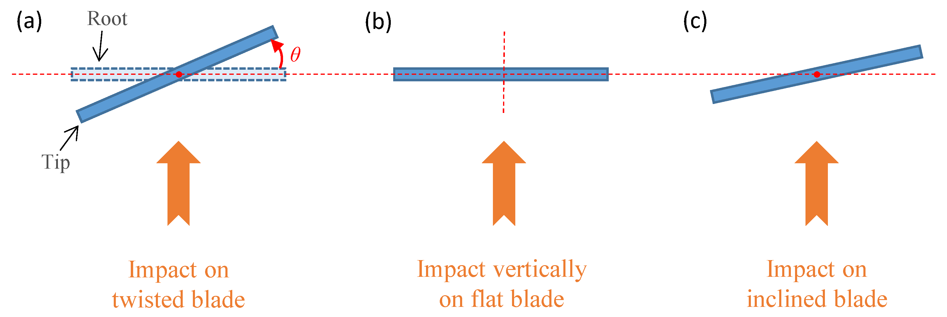
The blade was clamped supported on the root edge. The final numerical model of the impacted blade consists of 1340 conventional shell finite elements (linear quadrilateral elements S4R in ABAQUS). The failure modes are based on Hashin’s criteria formulation [40]. The material mechanical properties and fracture energies are needed in CDM modelling, of which the values are taken from References [41,42] as given in Table 2. Configuration designs of composite blades under bird impact are shown as Figure 2 (view from the tip). Figure 2a represents the twisted blade under impact; while (b) and (c) represent the vertical and inclined impact on flat blades respectively. It can be seen that (b) and (c) are axisymmetric and centrosymmetric, respectively. Therefore, the question is to investigate the damage equivalency of symmetrical configurations for the twisted configuration. In present simulations, the bird projectile impacts the half span of the blade, therefore the inclined angle (Figure 2c) is determined to the half of the twisted angle (θ in Figure 2a). The considered twisted angle was 36° and hence the inclined angle was 18°.

3. Results and Discussion

For the extremely discontinuous processes, an explicit dynamic analysis is appropriate to carry out using ABAQUS/Explicit, which can be computationally efficient for complex mechanics models with relatively short dynamic duration. In the present simulation, the projectile begins to initially contact the impacted plate at approximately 0.5 ms, and the total simulation duration is 6 ms.
Bird impacts with high kinetic energy can produce severe intra-laminar damages, e.g., fiber breakage and matrix cracking. In the failure modes of composite laminates, the fiber breakage could probably lead to catastrophic failure of overall laminated structures and then threaten the blade containment of aero-engines. Therefore, in the beginning of this section, attention is focused on the fiber-tension damage mode.
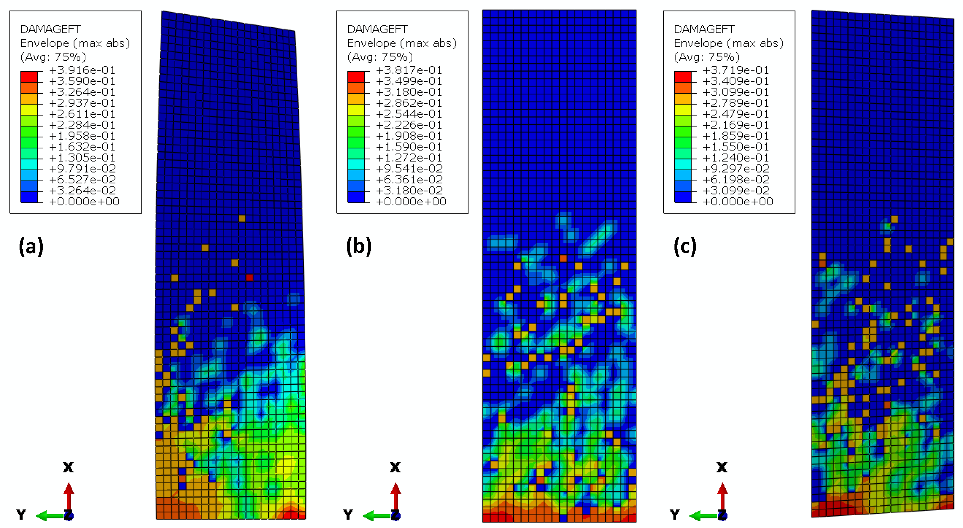
Figure 3 illustrates the damage maps of fiber-tension mode of the three configurations: (a) the twisted blade; (b) the flat blade; (c) the inclined-impacted flat blade. First, the maximum damages are close to each other: 0.3916, 0.3817, and 0.3719 respectively. Then, it can be observed that blade roots are all the highly-damaged areas for the three configurations, while damage distributions appear slightly different. At the roots, the vertically-impacted flat case (b) shows that high damage almost runs through along the root; however, in the twisted blade, high damage distributes at two corners of the root, with the left corner larger damaged area. This fact can be due to the twisted surface, with the left side is more front-facing than the right. From Figure 3c, it can be seen that the damage of inclined-impacted flat blade can reflect the corner-distributed feature. Thus, the inclined-impacted flat blade is more equivalent to the twisted blade in terms of fiber-tension damage.
For the fiber-compression damage mode, Figure 4 shows that both the axisymmetric and centrosymmetric configurations can describe the damage distribution of the twisted case relatively well. However, one disadvantage exists in that the damage distribution at the right corner cannot be well reflected. The fiber-compression damage in the twisted case indicates that the rear-forwarding area (right corner at the root) can be more easily subjected to fiber compression, which can lead to local buckling of fibers.
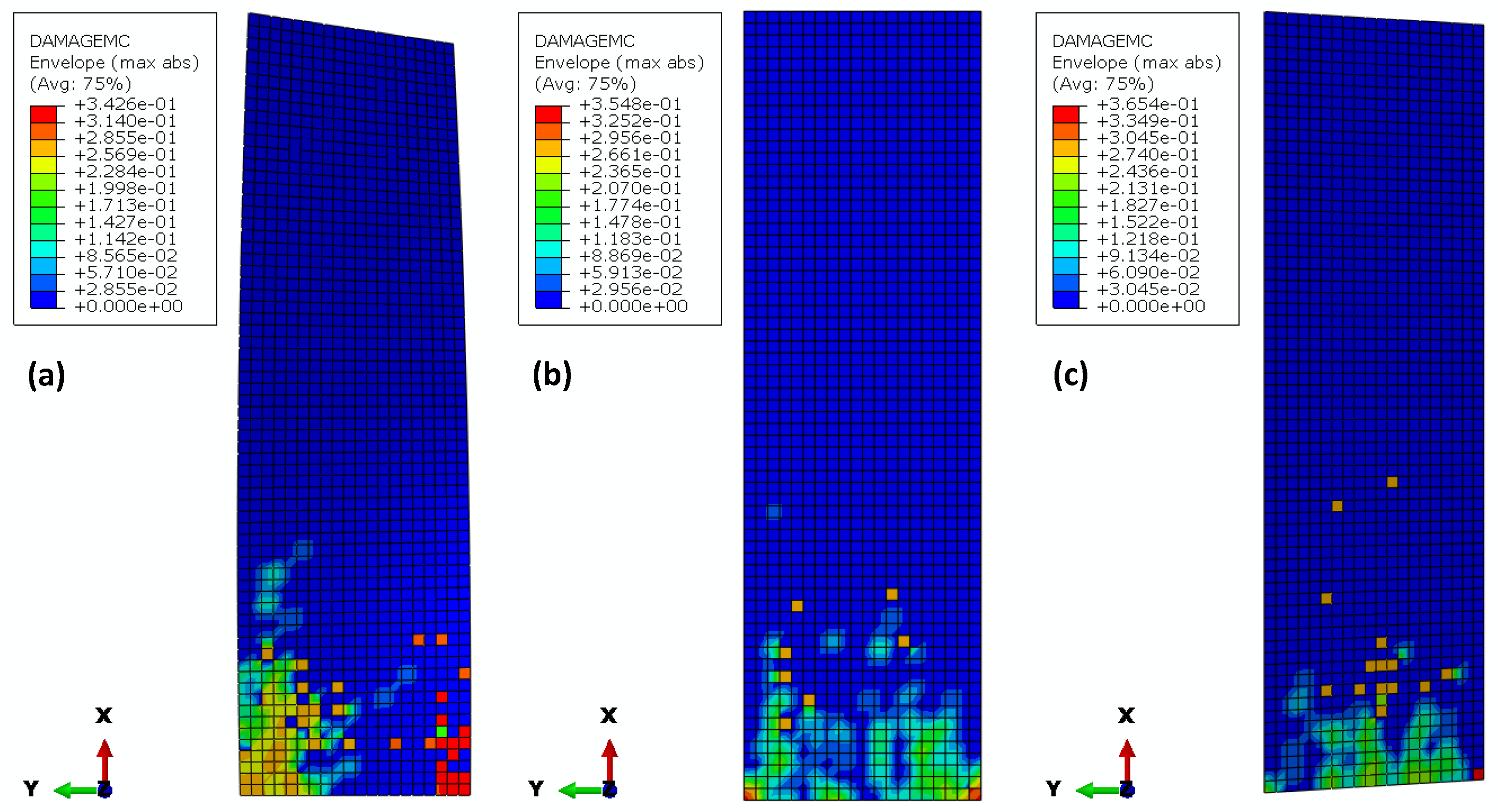
Figure 5 illustrates the damage maps of matrix-compression mode of the three configurations: (a) the twisted blade; (b) the vertically-impacted flat blade; (c) the inclined-impacted flat blade. First, the maximum damages are also close to each other: 0.3426, 0.3548, and 0.3654 respectively. Then, it can be observed that blade roots are all the highly-damaged area for the three configurations, while damage distributions appear quite different. At the roots, the result in vertically-impacted flat case (b) shows that high damage distributes at the root corners; however, in the twisted blade, although high damage also distributes at two corners of the root, but with the much larger damaged area distributed in both corners. This could also be due to the twisted surface, aggravating the matrix-compression damage. From Figure 5c, it can be seen that the damage of inclined-impacted flat blade cannot reflect the corner-distributed feature for the matrix-compression mode. Thus, in terms of matrix-compression damage, the two flat blades both failed to reflect the damage distribution of the twisted blade, to certain degree. Such phenomenon indicates that the flat laminates cannot perfectly reproduce the compressive deformations that the twisted laminate experiences, which is somewhat similar with the local distribution in fiber-compression case.
The matrix-tension damage can largely induce the stiffness degradation of laminated blades. Figure 6 shows that the matrix-tension damage distributions of the three cases are in good agreement on the whole, where extensive damages appeared except around the blade tip.
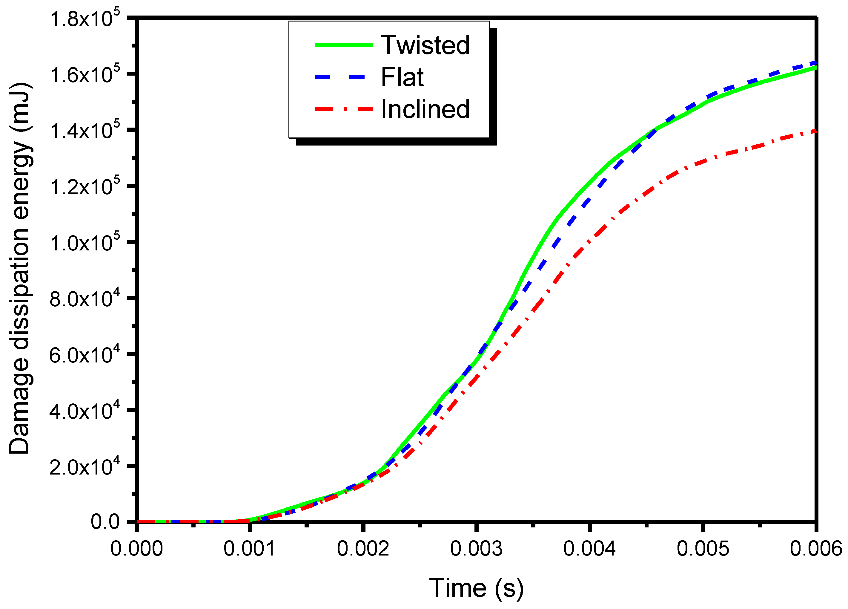
As an evolution process of inconvertible energy dissipation, damage dissipation energy denotes the energy dissipated by the laminate’s failure modes during the impact event. Figure 7 compares the time histories of the damage dissipation energies of the laminates in three configurations. Results indicate that vertically-impacted flat blade is quite adequate to reflect the real damage history in twisted blade case, while the inclined flat case performs inadequately, especially as the time increases. It is necessary to mention that it is difficult for the damage dissipation energy to be experimentally measured, due to the lack of straightforward measurement index.
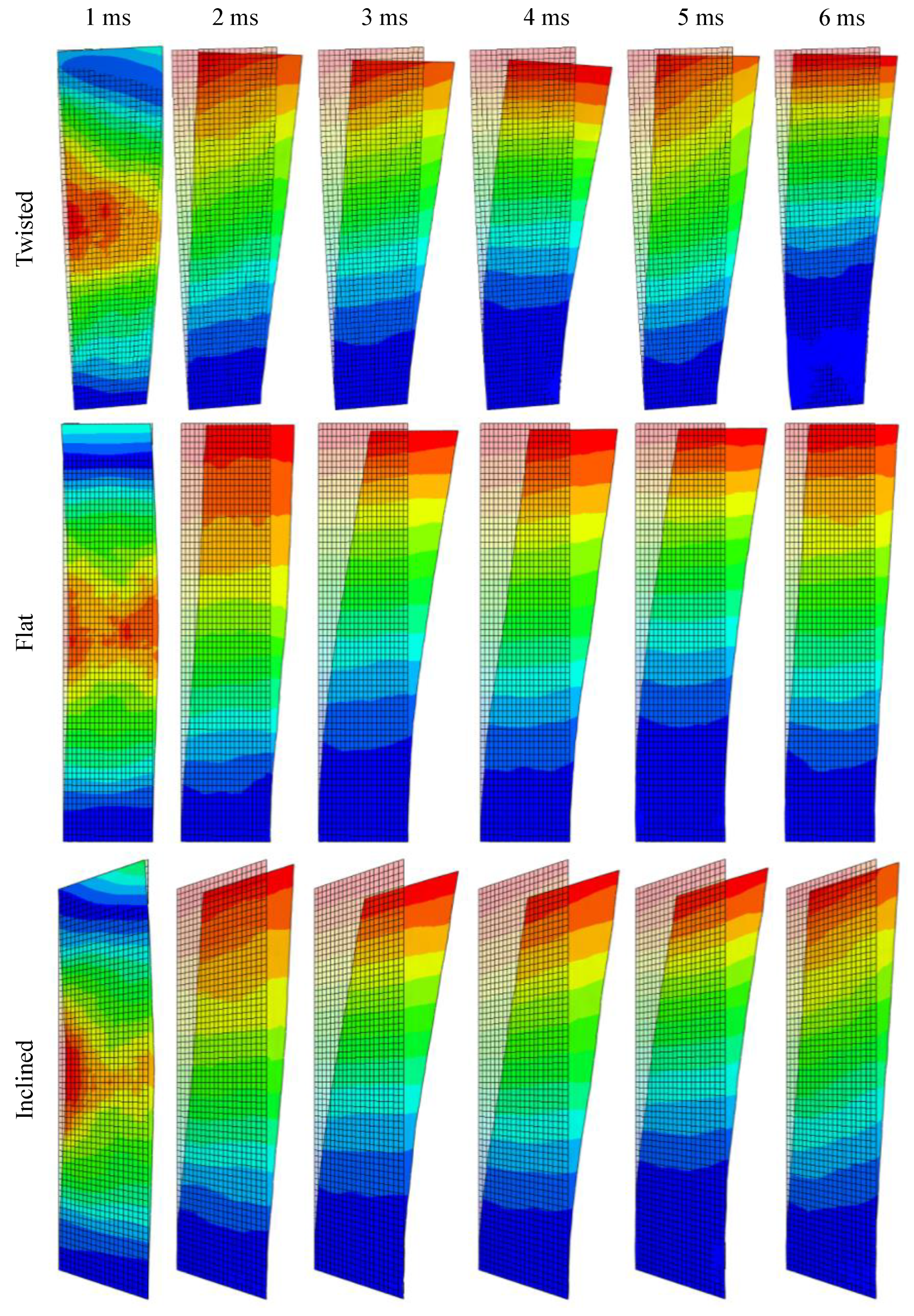
To further explain the damage results, Figure 8 demonstrates the deformation series of the three blades. In the twisted blade, the deformations had an oblique because of the asymmetry. However, the deformations were completely symmetric in the vertically-impacted flat plate, due to the strict symmetry of the system (the impacted plate and the bird projectile). It can be observed that the deformations of the inclined case also indicated an oblique impact, just as with the twisted blade. Therefore, it can be deduced that both the bending and torsion deformations happen in the twisted and inclined blades, while only bending deflection happens in the vertically-impacted flat blade.
The total contact forces generated in the three models along the impact direction are compared in Figure 9. Because the projectile began to initially contact the impacted plate at approximately 0.5 ms, the contact forces achieved the highest peak value also at approximately 0.5 ms in the three blades, which is due to the shock of Hugoniot pressure. It can be observed that the inclined blade is more equivalent to the twisted one, by comparing the highest peak values of the contact forces. However, the vertically-impacted flat blade is prone to overestimate the peak value of contact force. Such a result may be mainly due to the fact that the impact energy is mostly absorbed by the plate in such axisymmetric cases. On the contrary, the initial twist/inclination configuration and the induced torsion deformations can partially disperse the kinetic energy of the bird projectile.
Hereto, simulation results revealed some important laws for the damage distributions, damage energies, and contact forces in the different blade-like configurations. It can be seen that the replaceability and applicability of the simplified blade-like configurations (axisymmetric and centrosymmetric) can be different from different perspectives, which depend on the actual requirements to examine the crashworthiness of real fan blades. For instance, when the fatal fiber fracture or the peak force is the primary concern, the inclined case is the relative adequate choice. However, the vertically-impact flat case can well reflect the damage dissipation energy. These numerical results can provide a useful reference for aerospace engineers dealing with simplified and surrogate bird-strike experiments of complex fan blades. Finally, it is necessary to mention that the present study only considered the case in which the bird projectile impacts the central axis of the blade. It is worthwhile to investigate the replaceability when the impact location is off the central axis, where more complicated deformations can happen.

4. Conclusions

Considering the fact that cantilever slender flat plates are usually used for basic impact tests, for the purpose of a future simplified and surrogate experimental method, this article numerically investigated the damage equivalency for twisted composite blades under bird strike, by using SPH-FEM simulations. The impact-damage equivalency was considered by comparing damage modes and energy variations of three impact configurations: (1) the twisted blade to represent the real aero-engine fan blades; (2) the vertically-impacted flat blade (axisymmetric); and (3) the inclined flat blade (centrosymmetric). The damage maps, energy variations and deformations were comparatively investigated. It was found that:
The inclined-impacted flat blade is more equivalent to the twisted blade in terms of the fiber-tension damage and the contact force, which benefits from the similarity between the twisted and inclined configurations, such as the coupling bending and torsion deformations. On the whole, the inclined flat blade exhibits advantages over the vertically-impacted flat one in reproducing the fatal damage mode, the corner-distributed feature, and the oblique deformation.
For the fiber-compression damage mode, both the axisymmetric and centrosymmetric configurations can relatively well describe the damage distribution of the twisted case. However, in terms of the matrix-compression damage, the two flat blades both failed to adequately reflect the damage distribution of the twisted blade. It can be indicated that the flat laminates cannot perfectly reproduce the local compressive deformations that the twisted laminate experiences.
The three configurations showed similar matrix-tension damage maps, which were globally distributed. The vertically-impacted flat blade is quite adequate to reflect the real damage history in the twisted blade case, while the inclined flat case performs inadequately.
In brief, results indicate that both the vertically-impacted flat and inclined flat blades can be, to a certain extent, regarded as alternatives for real twisted blades under bird impact; however, both vertically-impacted flat and inclined flat blades have their own merits and drawbacks, and hence their replaceability and applicability should be carefully exploited for real engine blades in experimental evaluation, for the purpose of bridging the gap between the mechanism testing and the structural damage prediction.

Author Contributions

Conceptualization, Y.Z.; Data curation, Y.Z.; Formal analysis, Y.Z.; Funding acquisition, Y.S.; Investigation, Y.Z.; Methodology, Y.Z.; Project administration, Y.S. and T.H.; Resources, Y.S.; Software, Y.Z.; Supervision, Y.S.; Validation, T.H.; Visualization, Y.Z.; Writing—original draft, Y.Z.; Writing—review & editing, Y.Z.

Funding

This research was funded by the National Natural Science Foundation and the Civil Aviation Administration of China (U1333119); Shanghai Engineering Research Center of Civil Aircraft Health Monitoring (GCZX-2015-05); the Defense Industrial Technology Development Program (JCKY2013605B002); Fundamental Research Funds for the Central Universities (56XBC18206, 56XBA18201, IEA180017A19); the National Science and Technology Major Project (2017-VIII-0003-0114).

Conflicts of Interest

The authors declare no conflict of interest.

References

  1. Abrate, S. Soft impacts on aerospace structures. Prog. Aerosp. Sci. 2016, 81, 1–17. [Google Scholar] [CrossRef] [Green Version]
  2. Zhang, D.; Fei, Q. Effect of bird geometry and impact orientation in bird striking on a rotary Jet-Engine fan analysis using SPH method. Aerosp. Sci. Technol. 2016, 54, 320–329. [Google Scholar] [CrossRef]
  3. Zhang, Z.; Li, L.; Zhang, D. Effect of arbitrary yaw/pitch angle in bird strike numerical simulation using SPH method. Aerosp. Sci. Technol. 2018, 81, 284–293. [Google Scholar] [CrossRef]
  4. Meguid, S.A.; Mao, R.H.; Ng, T.Y. FE analysis of geometry effects of an artificial bird striking an aeroengine fan blade. Int. J. Impact Eng. 2008, 35, 487–498. [Google Scholar] [CrossRef]
  5. Mohagheghian, I.; Wang, Y.; Zhou, J.; Yu, L.; Guo, X.; Yan, Y.; Charalambides, M.N.; Dear, J.P. Deformation and damage mechanisms of laminated glass windows subjected to high velocity soft impact. Int. J. Solids Struct. 2017, 109, 46–62. [Google Scholar] [CrossRef]
  6. Zhou, J.; Liu, J.; Zhang, X.; Yan, Y.; Jiang, L.; Mohagheghian, I.; Dear, J.P.; Charalambides, M.N. Experimental and numerical investigation of high velocity soft impact loading on aircraft materials. Aerosp. Sci. Technol. 2019, 90, 44–58. [Google Scholar] [CrossRef]
  7. Grimaldi, A.; Sollo, A.; Guida, M.; Marulo, F. Parametric study of a SPH high velocity impact analysis—A birdstrike windshield application. Compos. Struct. 2013, 96, 616–630. [Google Scholar] [CrossRef]
  8. Hedayati, R.; Ziaei-Rad, S.; Eyvazian, A.; Hamouda, A.M. Bird strike analysis on a typical helicopter windshield with different lay-ups. J. Mech. Sci. Technol. 2014, 28, 1381–1392. [Google Scholar] [CrossRef]
  9. Riccio, A.; Cristiano, R.; Saputo, S.; Sellitto, A. Numerical methodologies for simulating Bird-Strike on composite wings. Compos. Struct. 2018, 202, 590–602. [Google Scholar] [CrossRef]
  10. Yu, Z.; Xue, P.; Yao, P.; Zahran, M.S. Analytical determination of the critical impact location for wing leading edge under birdstrike. Lat. Am. J. Solids Struct. 2019, 16, 1–17. [Google Scholar] [CrossRef]
  11. Di Caprio, F.; Cristillo, D.; Saputo, S.; Guida, M.; Riccio, A. Crashworthiness of wing leading edges under bird impact event. Compos. Struct. 2019, 216, 39–52. [Google Scholar] [CrossRef]
  12. Smojver, I.; Ivančević, D. Numerical simulation of bird strike damage prediction in airplane flap structure. Compos. Struct. 2010, 92, 2016–2026. [Google Scholar] [CrossRef]
  13. Orlando, S.; Marulo, F.; Guida, M.; Timbrato, F. Bird strike assessment for a composite wing flap. Int. J. Crashworthiness 2018, 23, 219–235. [Google Scholar] [CrossRef]
  14. Vignjevic, R.; Orłowski, M.; De Vuyst, T.; Campbell, J.C. A parametric study of bird strike on engine blades. Int. J. Impact Eng. 2013, 60, 44–57. [Google Scholar] [CrossRef]
  15. Liu, J.; Li, Y.; Gao, X. Bird strike on a flat plate: Experiments and numerical simulations. Int. J. Impact Eng. 2014, 70, 21–37. [Google Scholar] [CrossRef]
  16. Allaeys, F.; Luyckx, G.; Van Paepegem, W.; Degrieck, J. Characterization of real and substitute birds through experimental and numerical analysis of momentum, average impact force and residual energy in bird strike on three rigid targets: A flat plate, a wedge and a splitter. Int. J. Impact Eng. 2017, 99, 1–13. [Google Scholar] [CrossRef] [Green Version]
  17. Dar, U.A.; Zhang, W.; Xu, Y. FE Analysis of Dynamic Response of Aircraft Windshield against Bird Impact. Int. J. Aerosp. Eng. 2013, 2013, 1–12. [Google Scholar] [CrossRef]
  18. Mao, R.H.; Meguid, S.A.; Ng, T.Y. Transient three dimensional finite element analysis of a bird striking a fan blade. Int. J. Mech. Mater. Des. 2008, 4, 79–96. [Google Scholar] [CrossRef] [Green Version]
  19. Dar, U.A.; Awais, M.; Mian, H.H.; Sheikh, M.Z. The effect of representative bird model and its impact direction on crashworthiness of aircraft windshield and canopy structure. Proc. Inst. Mech. Eng. Part G J. Aerosp. Eng. 2019, 233, 5150–5163. [Google Scholar] [CrossRef]
  20. Georgiadis, S.; Gunnion, A.J.; Thomson, R.S.; Cartwright, B.K. Bird-Strike simulation for certification of the Boeing 787 composite moveable trailing edge. Compos. Struct. 2008, 86, 258–268. [Google Scholar] [CrossRef]
  21. Mohagheghian, I.; Charalambides, M.N.; Wang, Y.; Jiang, L.; Zhang, X.; Yan, Y.; Kinloch, A.J.; Dear, J.P. Effect of the polymer interlayer on the High-Velocity soft impact response of laminated glass plates. Int. J. Impact Eng. 2018, 120, 150–170. [Google Scholar] [CrossRef]
  22. Hedayati, R.; Sadighi, M. Effect of Using an Inner Plate between Two Faces of a Sandwich Structure in Resistance to Bird-Strike Impact. J. Aerosp. Eng. 2016, 29, 04015020. [Google Scholar] [CrossRef]
  23. Hu, D.; Song, B.; Wang, D.; Chen, Z. Experiment and numerical simulation of a Full-Scale helicopter composite cockpit structure subject to a bird strike. Compos. Struct. 2016, 149, 385–397. [Google Scholar] [CrossRef]
  24. Wang, J.; Xu, Y.; Zhang, W. Finite element simulation of PMMA aircraft windshield against bird strike by using a rate and temperature dependent nonlinear viscoelastic constitutive model. Compos. Struct. 2014, 108, 21–30. [Google Scholar] [CrossRef]
  25. Roberts, G.D.; Revilock, D.M.; Binienda, W.K.; Nie, W.Z.; Mackenzie, S.B.; Todd, K.B. Impact Testing and Analysis of Composites for Aircraft Engine Fan Cases. J. Aerosp. Eng. 2002, 15, 104–110. [Google Scholar] [CrossRef]
  26. Higuchi, R.; Okabe, T.; Yoshimura, A.; Tay, T.E. Progressive failure under High-Velocity impact on composite laminates: Experiment and phenomenological mesomodeling. Eng. Fract. Mech. 2017, 178, 346–361. [Google Scholar] [CrossRef]
  27. Minak, G.; Abrate, S.; Ghelli, D.; Panciroli, R.; Zucchelli, A. Low-Velocity impact on carbon/epoxy tubes subjected to torque–Experimental results, analytical models and FEM analysis. Compos. Struct. 2010, 92, 623–632. [Google Scholar] [CrossRef]
  28. Saghafi, H.; Minak, G.; Zucchelli, A. Effect of preload on the impact response of curved composite panels. Compos. Part B Eng. 2014, 60, 74–81. [Google Scholar] [CrossRef]
  29. Heimbs, S.; Bergmann, T. High-Velocity Impact Behaviour of Prestressed Composite Plates under Bird Strike Loading. Int. J. Aerosp. Eng. 2012, 2012, 1–11. [Google Scholar] [CrossRef]
  30. Guida, M.; Sellitto, A.; Marulo, F.; Riccio, A. Analysis of the Impact Dynamics of Shape Memory Alloy Hybrid Composites for Advanced Applications. Materials 2019, 12, 153. [Google Scholar] [CrossRef] [PubMed]
  31. Friedrich, L.A. Impact Resistance of Hybrid Composite Fan Blade Materials; NASA: Washington, DC, USA, 1974. [Google Scholar]
  32. Hou, J.P.; Ruiz, C. Soft body impact on laminated composite materials. Compos. Part A Appl. Sci. Manuf. 2007, 38, 505–515. [Google Scholar] [CrossRef]
  33. Liu, L.; Luo, G.; Chen, W.; Zhao, Z.; Huang, X. Dynamic Behavior and Damage Mechanism of 3D Braided Composite Fan Blade under Bird Impact. Int. J. Aerosp. Eng. 2018, 2018, 1–16. [Google Scholar] [CrossRef]
  34. Nishikawa, M.; Hemmi, K.; Takeda, N. Finite-Element simulation for modeling composite plates subjected to soft-body, High-Velocity impact for application to bird-strike problem of composite fan blades. Compos. Struct. 2011, 93, 1416–1423. [Google Scholar] [CrossRef]
  35. Zhou, Y.; Sun, Y.; Cai, W. Bird-Striking damage of rotating laminates using SPH-CDM method. Aerosp. Sci. Technol. 2019, 84, 265–272. [Google Scholar] [CrossRef]
  36. Ten Years of “Twisting” a Fan Blade, This Innovative Technology Is about to Affect Your Airplane. 2018. Available online: http://www.sohu.com/a/234993331_660773 (accessed on 27 July 2019).
  37. Heimbs, S. Computational methods for bird strike simulations: A review. Comput. Struct. 2011, 89, 2093–2112. [Google Scholar] [CrossRef]
  38. Liu, J.; Li, Y.; Yu, X.; Tang, Z.; Gao, X.; Lv, J.; Zhang, Z. A novel design for reinforcing the aircraft tail leading edge structure against bird strike. Int. J. Impact Eng. 2017, 105, 89–101. [Google Scholar] [CrossRef]
  39. Taddei, L.; Awoukeng Goumtcha, A.; Roth, S. Smoothed particle hydrodynamics formulation for penetrating impacts on ballistic gelatine. Mech. Res. Commun. 2015, 70, 94–101. [Google Scholar] [CrossRef]
  40. Hashin, Z.; Rotem, A. A Fatigue Failure Criterion for Fiber Reinforced Materials. J. Compos. Mater. 1973, 7, 448–464. [Google Scholar] [CrossRef] [Green Version]
  41. Riccio, A.; Ricchiuto, R.; Saputo, S.; Raimondo, A.; Caputo, F.; Antonucci, V.; Lopresto, V. Impact behaviour of omega stiffened composite panels. Prog. Aerosp. Sci. 2016, 81, 41–48. [Google Scholar] [CrossRef]
  42. Smojver, I.; Ivančević, D. Bird strike damage analysis in aircraft structures using Abaqus/Explicit and coupled Eulerian Lagrangian approach. Compos. Sci. Technol. 2011, 71, 489–498. [Google Scholar] [CrossRef] [Green Version]
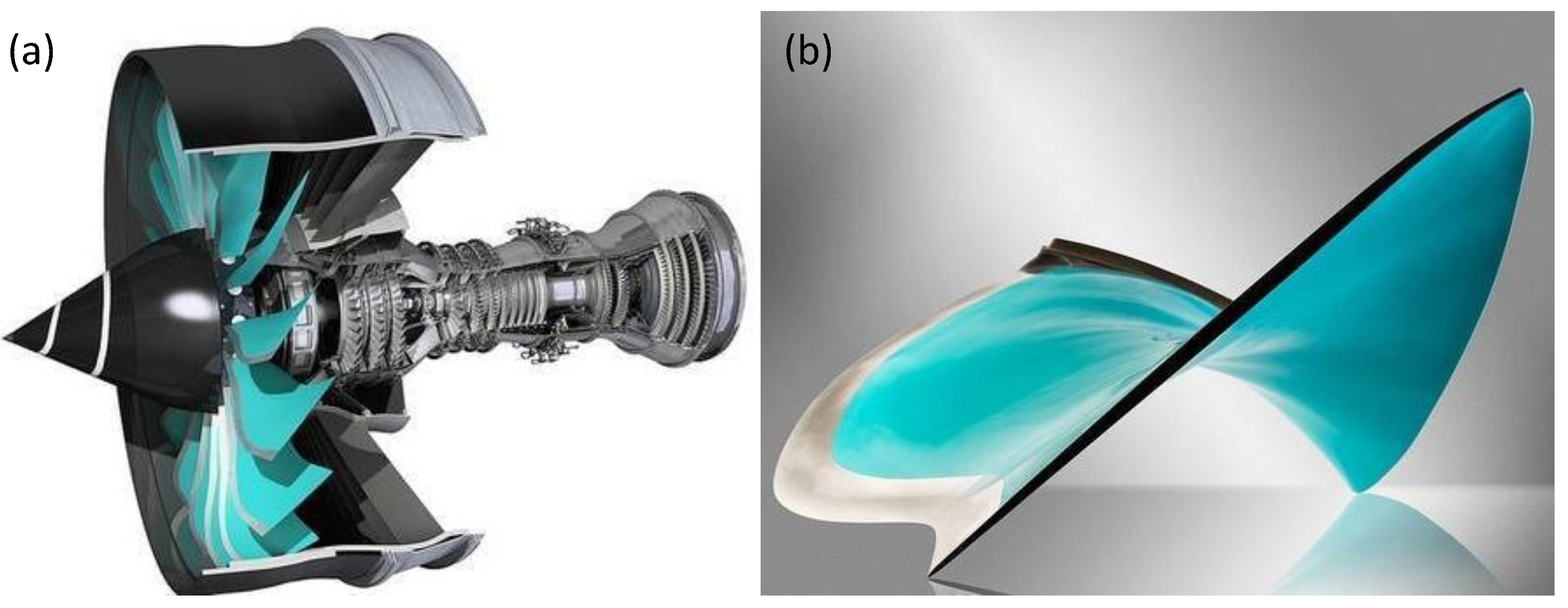
Figure 1. An example of aero-engine and one of its fan blades (a) the turbofan engine; (b) the twisted fan blade [36].
Symmetry 11 01292 g001
Figure 2. Configuration designs for composite blades under bird impact (view from the tip).
Symmetry 11 01292 g002
Figure 3. Fiber-tension damage maps of the three impacted configurations. (a) the twisted blade; (b) the flat blade; (c) the inclined-impacted flat blade.
Symmetry 11 01292 g003
Figure 4. Fiber-compression damage maps of the three impacted configurations. (a) the twisted blade; (b) the flat blade; (c) the inclined-impacted flat blade.
Symmetry 11 01292 g004
Figure 5. Matrix-compression damage maps of the three impacted configurations. (a) the twisted blade; (b) the flat blade; (c) the inclined-impacted flat blade.
Symmetry 11 01292 g005
Figure 6. Matrix-tension damage maps of the three impacted configurations. (a) the twisted blade; (b) the flat blade; (c) the inclined-impacted flat blade.
Symmetry 11 01292 g006
Figure 7. Time histories of damage dissipation energies in the three configurations.
Symmetry 11 01292 g007
Figure 8. Deformation series of the three blades.
Symmetry 11 01292 g008
Figure 9. Contact forces of the three models.
Symmetry 11 01292 g009
Table 1. The considered plies and dimensions for blades.
Ply AnglesPly NumberTotal Thickness (mm)In-Plane Dimensions (mm × mm)
[0/45/0/-45/-45/0/45/0]s1648500 × 150
Table 2. Material mechanical properties of the unidirectional lamina.
PropertiesValue
Mass density1600 kg/m3
Orthotropic elastic propertiesE11 = 181,000 MPa; E22 = 10,300 MPa; ν12 = 0.28;
G12 = 7170 MPa; G13 = 1000 MPa; G23 = 500 MPa
Strength propertiesXT = XC = 1500 MPa; YT = 40 MPa;
YC = 246 MPa; S12 = 200 MPa; S13 = 123 MPa
Fracture energies G 1 c T = 11.5 kJ/m2; G 2 c T = 4.1 kJ/m2;
G 1 c C = 0.35 kJ/m2; G 2 c C = 3.2 kJ/m2