Article

Study of a Null-Flux Coil Electrodynamic Suspension Structure for Evacuated Tube Transportation

1
Maglev Research Center, College of Intelligence Science and Technology, National University of Defense Technology, Changsha 410073, China
2
State Key Laboratory of Functional Materials for Informatics, Shanghai Institute of Microsystem and Information Technology, Chinese Academy of Sciences, Shanghai 200050, China
*
Authors to whom correspondence should be addressed.
Symmetry 2019, 11(10), 1239; https://doi.org/10.3390/sym11101239
Submission received: 4 September 2019 / Revised: 24 September 2019 / Accepted: 25 September 2019 / Published: 3 October 2019

Abstract

:
This paper focuses on the study of a null-flux coil electrodynamic suspension structure for evacuated tube transportation (ETT). A Maglev system in evacuated tubes is a promising concept for high speed transportation systems, and the design of levitation structure is a critical part among the subsystems. The whole system with functions of levitation, guidance, and propulsion is proposed in this paper, and the utilization of magnetic fields from both sides of magnets makes the system simple. The figure eight shaped null-flux coil suspension structure is adopted to provide a high levitation-drag ratio. The equivalent circuit model of the null-flux coil structure is established by employing the dynamic circuit theory. Based on the determination of the mutual inductance between the null-flux coil and the moving magnet, electromagnetic forces are calculated through an energy method. The validity of the dynamic circuit model is verified by comparing the calculation with the 3D finite element analysis (FEM) results, and the working principle of the null-flux coil structure is described. The effects of vehicle speed and the time constant of the coil on the electromagnetic forces are studied at the bottom level of force impulses in one coil and verified by FEM simulation. The characteristics of electrodynamic forces as functions of the magnet speed, the vertical displacements, and the lateral displacements are investigated based on the dynamic circuit theory, and the levitation-drag ratio is compared with that of plate type structure. The results show that the proposed structure is a promising option for application in ETT, and the following study will focus on the dynamic research of the electrodynamic suspension (EDS) system.

Graphical Abstract

1. Introduction

The research of ground high speed transportation is popular because of the increasing need for a faster, safer, and cheaper transportation mode. Ground transportation could be divided into two kinds of structure: a wheel-rail type one and a contactless one. Magnetic levitation (maglev) is the most promising and widely used contactless technology, and has been successfully applied in the fields of trains, bearing, motors, and so on [1,2,3,4]. Unlike conventional train driving forward by frictions between wheels and rails, a maglev train replaces wheels with magnets, levitates on the rails, and produces propulsion force electromechanically without any contact [5]. There are several advantages of maglev transportation: lower noise, less maintenance costs, being hard to derail, being able to run through curves in a smaller radius, and so on [6]. Among the running commercial lines, the top speed of wheel-rail transportation is about 350 km/h from the Fuxing bullet train in China, and the highest maglev train speed is 430 km/h from Shanghai maglev line [7]. It can be seen that both of these have a long distance requirement compared with an airliner, whose cruising speed could be more than 900 km/h. Air friction is one of the main critical obstacles for developing ground transportation with higher speeds, which is proportional to the square of the train speed. Although the concept of train traveling in evacuated tubes is an old idea and the related technical proposals have been published for several decades [8], it is now a popular research topic, especially after the announcement of the Hyperloop by Elon Musk in 2013 [9]. The core idea of evacuated tube transportation (ETT) is to minimize air friction, and the feasibility of ETT has been studied and verified by research institutes and the transportation industry. For example, the Space Exploration Technologies Corporation (SpaceX) has organized the Hyperloop pod prototypes student competition for three years, and participant teams could design and test their models on the 1.6 km long test line. The current speed record of 457 km/h was made by the WARR Hyperloop team in 2018.
It is necessary to adopt the maglev structure to minimize frictions, noises, and vibrations in the ETT system design. Based on the levitation principles, there are two main kinds of maglev systems: an Electromagnetic Suspension (EMS) attraction system and an Electrodynamic Suspension (EDS) repulsion system. Electromagnetic attractive forces are generated between the magnet and the ferromagnetic rail to achieve levitation at the expected gap, and active control is needed [10,11,12], since EMS is an open-loop unstable system in essence. Different from EMS, the levitation force of EDS is formed by interaction between the magnet and the non-ferromagnetic conducive rail [13,14]. The eddy current is induced in the conductive rail when the magnet producing high magnetic fields moves along the ground conductor, and the eddy current interacts with the magnet to produce the repulsive force and levitate the train [15]. In other words, the change of magnetic flux is the fundamental source of the levitation force in the EDS system. The EDS structure is an essential open-loop stable system and does not need active control. A superconducting (SC) magnet and permanent magnet (PM) are usually adopted as the excitation source and the EDS can be divided into two types based on the type of rail: a continuous one and a discrete one. The continuous track composed of a non-ferromagnetic plate and the Holloman High Speed Test Track (after a maglev update) propelled by solid fuel rocket motor is a typical continuous EDS [16], whose test speed reached 673 km/h in 2008. The superconducting maglev train made by Japan Rail (JR) Company is a representative of a discrete EDS, which adopts a null-flux coil to generate a high levitation-drag ratio [17]. The SC maglev train provided the ground transportation speed record of 603 km/h on the Yamanashi Line in 2015. Apart from EMS and EDS, flux-pinning levitation with high-temperature superconductors (HTS) is another candidate for ETT. The vehicle could achieve suspension above a permanent magnet guideway by utilizing the flux-pinning property of type-II superconductors, and the first prototype of the test system with a length of 45 m was developed by Deng et al. [18]. This structure has advantages of a simple structure, self-stability, and so on, but the construction and the maintenance of a long permanent magnet guideway is a problem to be solved, which could increase the cost.
Although EMS has the advantages of active control and adjusting the dynamic performance, EDS is preferred in the EET application. First, the heavy electromagnet and the ancillary equipment needed for active control, such as signal detection, a power supply, and a control system, make the whole system complex, especially because the space in the evacuate tube is limited. Second, the obvious eddy current in the ferromagnetic rail reduces the levitation force and provides increasing current and heat in the electromagnet [19,20], however the heat dissipation is not an easy thing to achieve in an evacuated tube. Third, high speed operation makes real-time control hard and high accuracy is not easy achieve. So, EDS has gained more attention in ETT research compared with EMS at present. Abdelrahman et al. conducted the design and prototyping of a Hyperloop pod levitation and propulsion system, and the approach was verified by FEM simulation [21]. An all-in-one system for Hyperloop that conducts levitation, propulsion, and guidance was presented by Ji et al., a conductive plate structure was adopted, and the parameters that affect the system performance were analyzed [22].
This paper focuses on the design and analysis of a null-flux EDS structure for an ETT system. The whole system integrated with levitation, guidance, and propulsion is presented, and both sides of the magnets are utilized in the design. The null-flux coil levitation structure is analyzed by the equivalent circuit model based on the dynamic circuit theory. The mutual inductance between the magnet and the coil is calculated, and the electrodynamic forces are determined by the energy method. The mechanism of the null-flux coil is presented, and the calculation results of the dynamic circuit model are verified by the FEM analysis. The effect of vehicle speed and the time constant of coil on magnetic forces are studied at the bottom level of the force impulse. The characteristics of the electromagnetic forces are studied and compared with a plate type EDS structure, and the analysis results at constant speeds have shown that the null-flux coil EDS structure is promising for application in the ETT system.

2. Proposed ETT System

The technical focus of ETT has three main aspects: the low cost construction of an evacuated tube, a magnetic structure, and propulsion system designs. The tube construction will not be included here, but the restricted tube space raises a higher standard for simplicity of the whole system. The superconducting magnet needs cooling auxiliary devices and magnetic shielding for coach, and there could be obvious eddy currents in the metal tube wall during the motion. So, permanent magnet is used as excitation source in the design. EDS structure is preferred in the ETT design, while a null-flux coil type was adopted due to its ability to provide a higher levitation-drag ration compared with plate type EDS. The comparison detail is provided in Section 3.4.2. The linear motor must be adopted because of its straight motion. A linear induction motor is restricted to dealing with propulsion force density and working efficiency together. As an example, the parallel linear induction motors could provide high force density, but their efficiency is low. As such, a linear synchronous motor is preferred. The motor with iron material has saturation property, meaning the permittivity will drop promptly when the magnetic field increases to some strong level, and the core lose will become larger with the increasing of the magnetic field and the motor speed. The linear synchronous motor with hollow stator coils is chosen in the end.
The designed ETT system is composed of three parts: a tube, vehicle, and rail, as shown in Figure 1. The vehicle body is mounted upon the propulsion stator and the magnets are placed on both lateral sides of the vehicle body. Null-flux coils are embedded in the lateral symmetrical guideways to provide levitation and guidance. Axis X is the lateral direction, axis Y is the vehicle moving direction, and axis Z is the vertical direction where the vehicle is levitated. When the magnet aboard moves along the rails, the eddy current is induced in the null-flux coils and the interaction between the magnet and the eddy current in the coils will generate levitation, guidance, and drag forces. The linear synchronous motor is composed of long hollow stator coils and the magnet mover. Both sides of magnets are used in the system to get high utilization of magnetic fields and simplify the whole structure. Three-phase AC is controlled in the stator coils to generate traveling wave magnetic fields, which interact with the magnets aboard to realize electromagnetic thrust and synchronous motion. The deceleration is conducted by reversing the direction of the stator currents to produce braking forces, and the drag forces from null-flux coils could also make a contribution.

3. Analysis of the Null-Flux Coil EDS Structure

A null-flux coil structure is an important guideway conductor configuration in EDS system design, and the concept of a figure eight shaped null-flux coil was invented by Powell and Danby in the 1960s [23]. The patent was bought by JR Company and then used in the SC maglev train design. The maglev train then reached a ground transportation speed record of 603 km/h on the Yamanashi Line in 2015. The most outstanding feature of the figure eight shaped null-flux coil structure is its capacity to provide both levitation and guidance forces with a high lift-drag ratio. Although there are much work that has been done before on the calculation, experiments, and analysis of the null-flux coil structure, in this paper FEM simulation is adopted and compared with the calculation, the effects of magnet speed and the time constant of coil on magnetic forces are studied at the basic and bottom level (change of force impulses in one coil during motion) and the results are verified by FEM simulation. Then the properties of null-flux structure are studied and the result of the levitation-drag ratio is compared with that of a plate type EDS structure.

3.1. Working Principles of Null-Flux Coil Structure

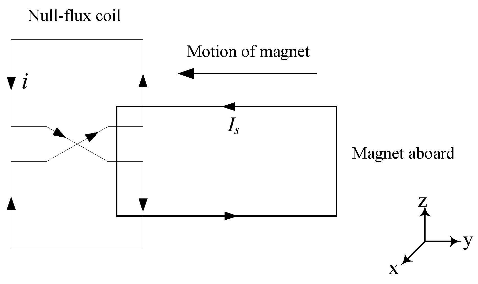
The mechanism of a figure eight shaped null-flux coil is shown in Figure 2, which can be explained by the Lenz law [24]. The magnet aboard moves along the null-flux coil rail, and the position where the mid-line of the magnet coincides with that of the coil is considered as the balance position. The overlap areas of the magnet with the upper and the lower loops are the same at the balance line. And although the same induced voltages are generated in both loops due to the change of flux when the magnet moves, the voltage is cancelled out and there is no induced current in the figure eight coil because of the cross connection. Then no electromagnetic forces are generated at the balance position. When the magnet moves along the coil downwards from the balance line as shown in Figure 2, the overlap area between the magnet and the lower loop is larger than that of the upper loop, and the induced voltage in the lower loop is stronger than in the upper one. Then the induced current is generated in the coil and the magnetic field produced by the induced current will hinder the change of flux according to Lenz law. The eddy current in the ground conductor is proportional to the flux linkage and its change rate on time. The magnitude of flux linkage is a geometry function of magnet and the change rate is a function of magnet velocity. The electromagnetic force on moving magnet in axis Z is composed of two parts: a repulsive force from the lower loop and an attractive force from the upper loop, so the result is a vertical levitation force. Similarly, the guidance and the drag forces are generated according to Lenz law.

3.2. Equivalent Circuit of Null-Flux Coil Levitation Structure

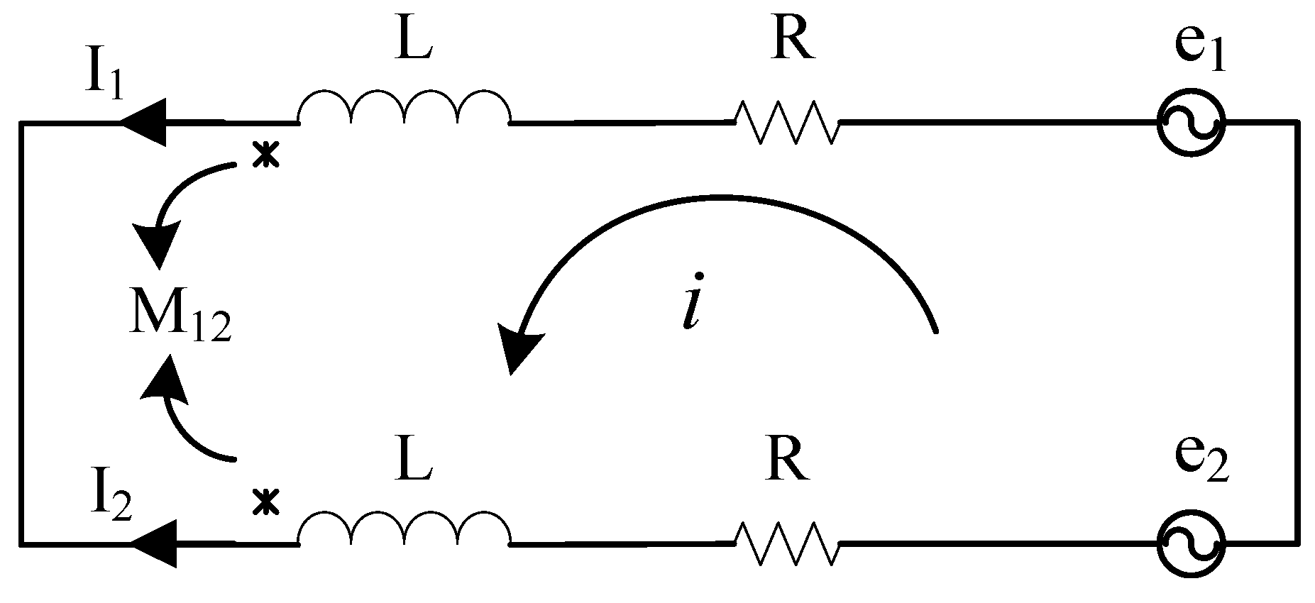
Electromagnetic field method and electrical circuit method are two mainly used approaches for the calculation of magnetic forces. The dynamic circuit model is a typical electrical circuit method, in which the circuit components involving relative motion and the parameters are functions of time and displacement. The method is especially suited for analysis of null-flux coil EDS structure, and the circuit parameters including resistance and inductance are simple to calculate. The figure eight shaped null-flux coil could be twisted to an equivalent closed loop circuit consisting of two branches [25], which is shown in Figure 3. The upper and the lower loop of figure eight coil are represented by a branch with resistance R and inductance L. The coupling between the magnet and the two loops of the coil are described by the induced voltages e1 and e2, respectively, and the coupling between the two loops is modeled by the mutual inductance M12. The currents flowing in the upper and the lower loops are I1 and I2. Ms1 and Ms2 are mutual inductances between the moving magnet and the upper and the lower loops.
The induced voltages e1 and e2 can be obtained based on the principle of electromagnetic induction:
e 1 = I s v M s 1 ( x , y , z ) x e 2 = I s v M s 2 ( x , y , z ) x .
The voltage equation of the equivalent circuit in Figure 3 is:
2 R i + 2 ( L M 1 , 2 ) d i d t = e 1 e 2 .
The energy in the interaction between the magnet and the upper and the lower loops is:
W 1 = M s 1 I s I 1 W 2 = M s 2 I s I 2 .
Then the electromagnetic forces generated between the magnet and the coil can be obtained:
f x = W 1 x + W 2 x = I s I 1 M s 1 x + I s I 2 M s 2 x = I s i ( M s 1 x M s 2 x ) f y = W 1 y + W 2 y = I s I 1 M s 1 y + I s I 2 M s 2 y = I s i ( M s 1 y M s 2 y ) f z = W 1 z + W 2 z = I s I 1 M s 1 z + I s I 2 M s 2 z = I s i ( M s 1 z M s 2 z ) .
It can be seen that the electromagnetic forces are decided by currents in the magnet and the coil, and the gradient of mutual inductances in three directions between the magnet and the upper and the lower loops. Since the mutual inductances is variables related with time and relative position, the induced current in null-flux coil could only be calculated through numerical methods from Equation (2). The average value can be obtained by integration of time dependent magnetic forces within the operating time:
F x = 1 T 0 T I s i ( M s 1 x M s 2 x ) d t F y = 1 T 0 T I s i ( M s 1 y M s 2 y ) d t F z = 1 T 0 T I s i ( M s 1 z M s 2 z ) d t
The critical mutual inductance is calculated based on the Neumann Formula:
M = μ 0 4 π c 1 c 2 d l 1 · d l 2 r = μ 0 4 π c 1 c 2 d x d x + d y d y + d z d z ( x x ) 2 + ( y y ) 2 + ( z z ) 2
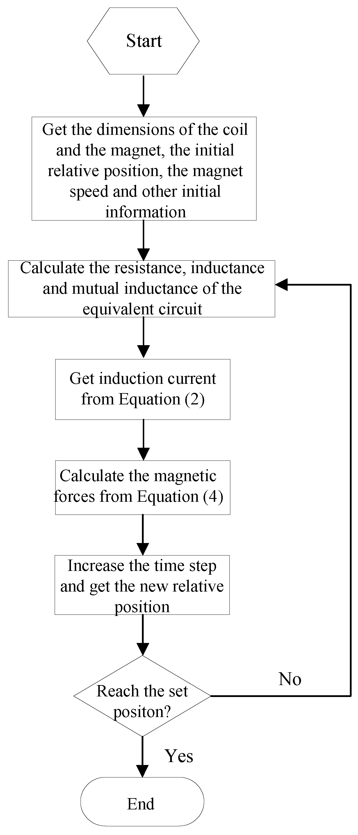
where μ 0 is the vacuum permeability, (x, y, z) and (x′, y′, z′) are coordinates of magnets and null-flux coil, respectively. Then, the flow chart of the calculation process of electromagnetic forces is shown in Figure 4.

3.3. Verification of Dynamic Circuit Theory

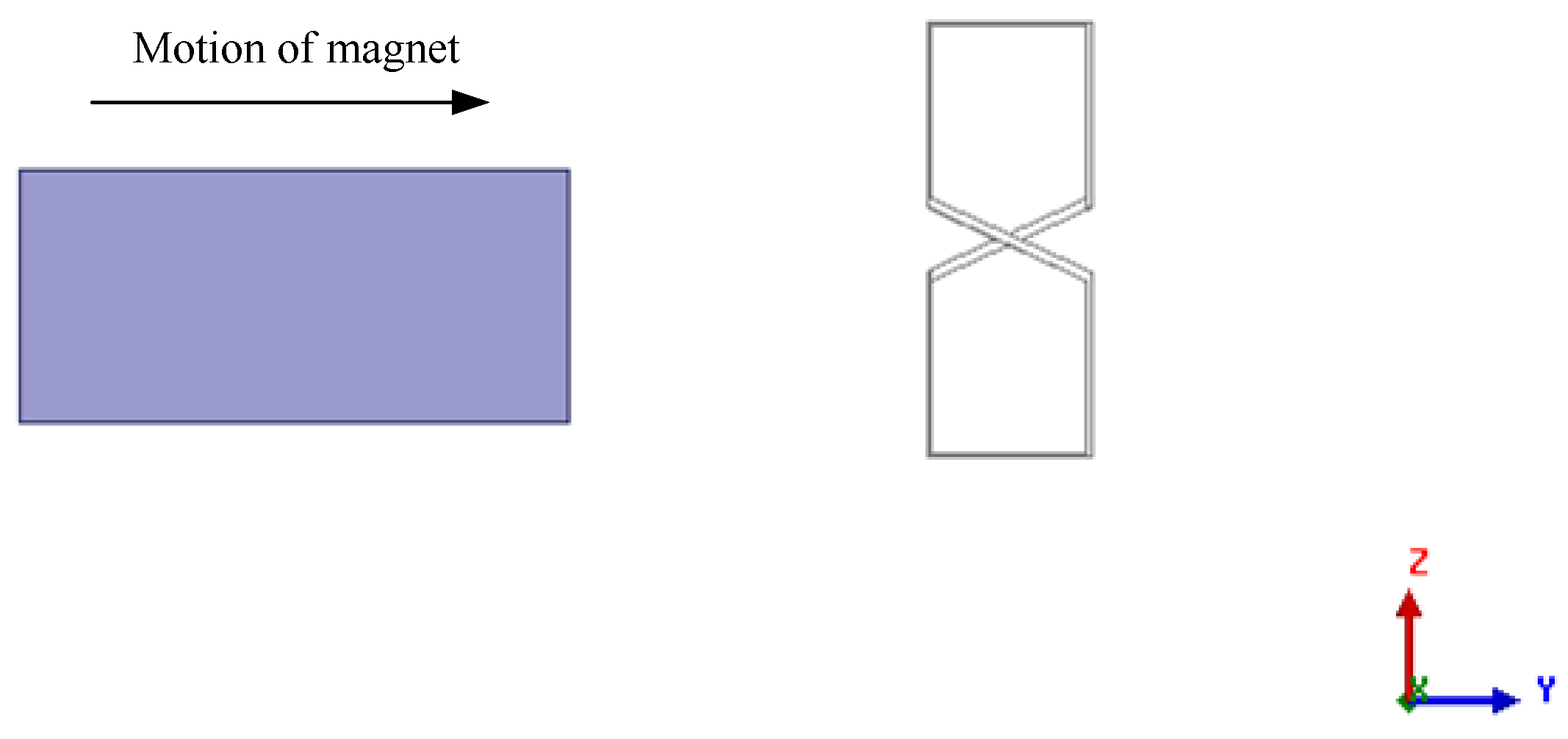
3D finite element simulation using ANSYS Maxwell is adopted to verify the calculation results of the dynamic circuit theory. The verification is conducted on the interaction between one null-flux coil and one PM, and the simulation model is shown in Figure 5. The parameters of the model are listed in Table 1.
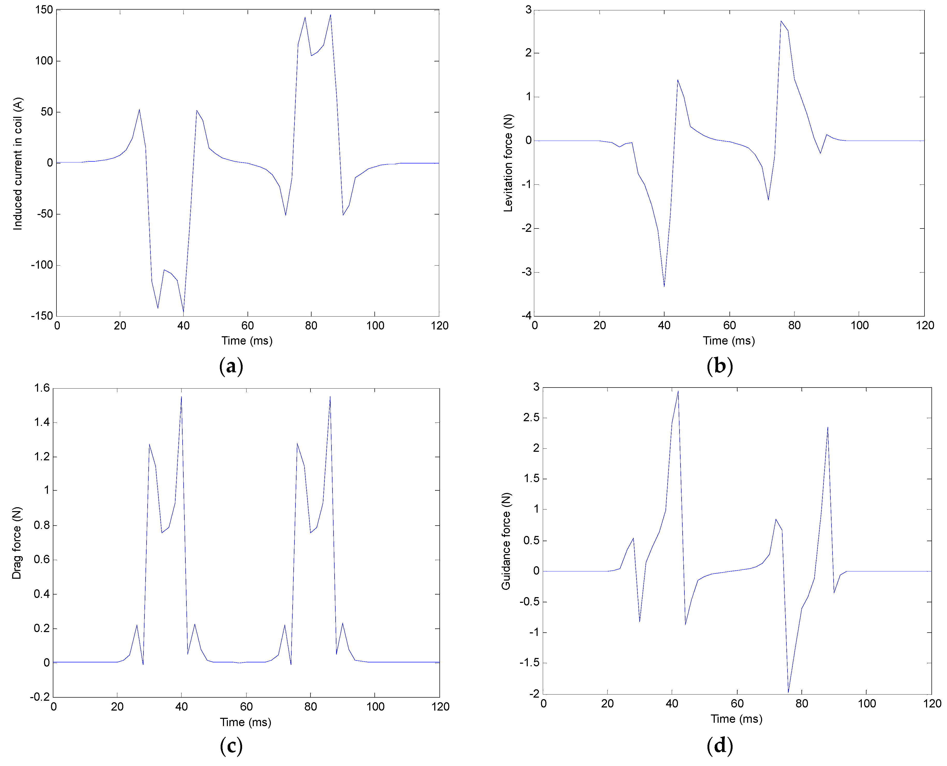
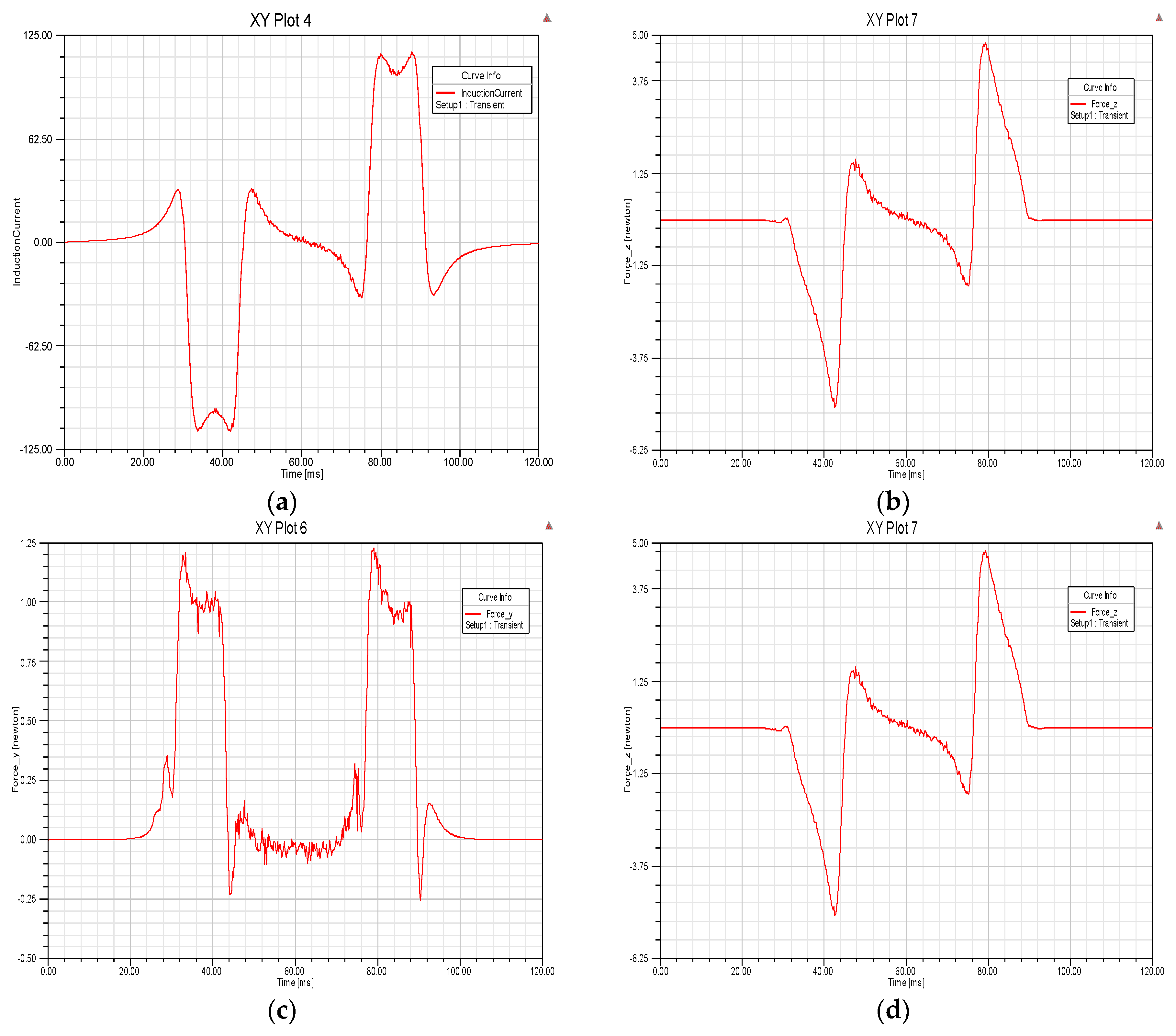
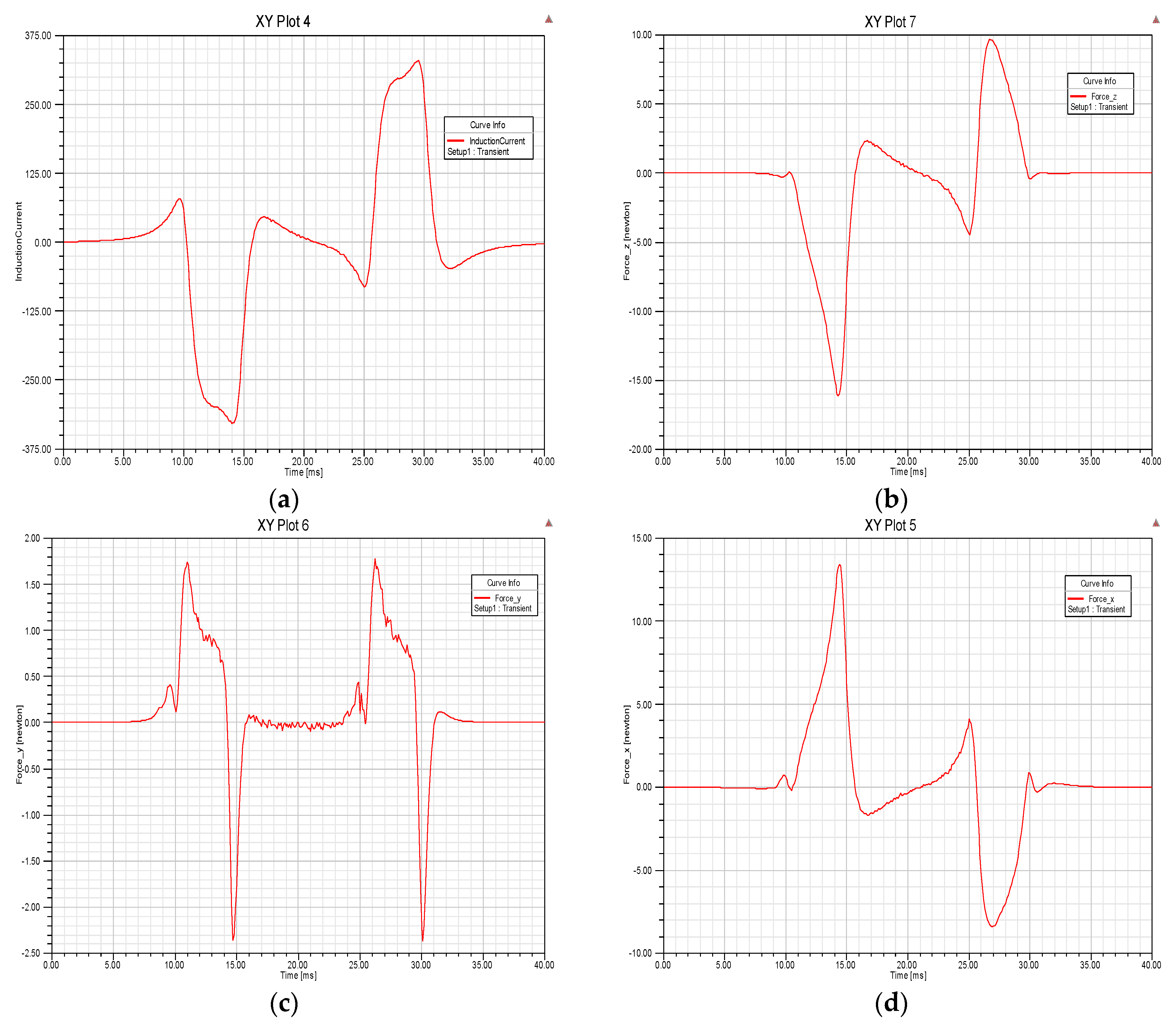
The calculation and the FEM simulation results of the induced current in the coil and the magnetic forces in three axes are shown in Figure 6 and Figure 7, respectivel.
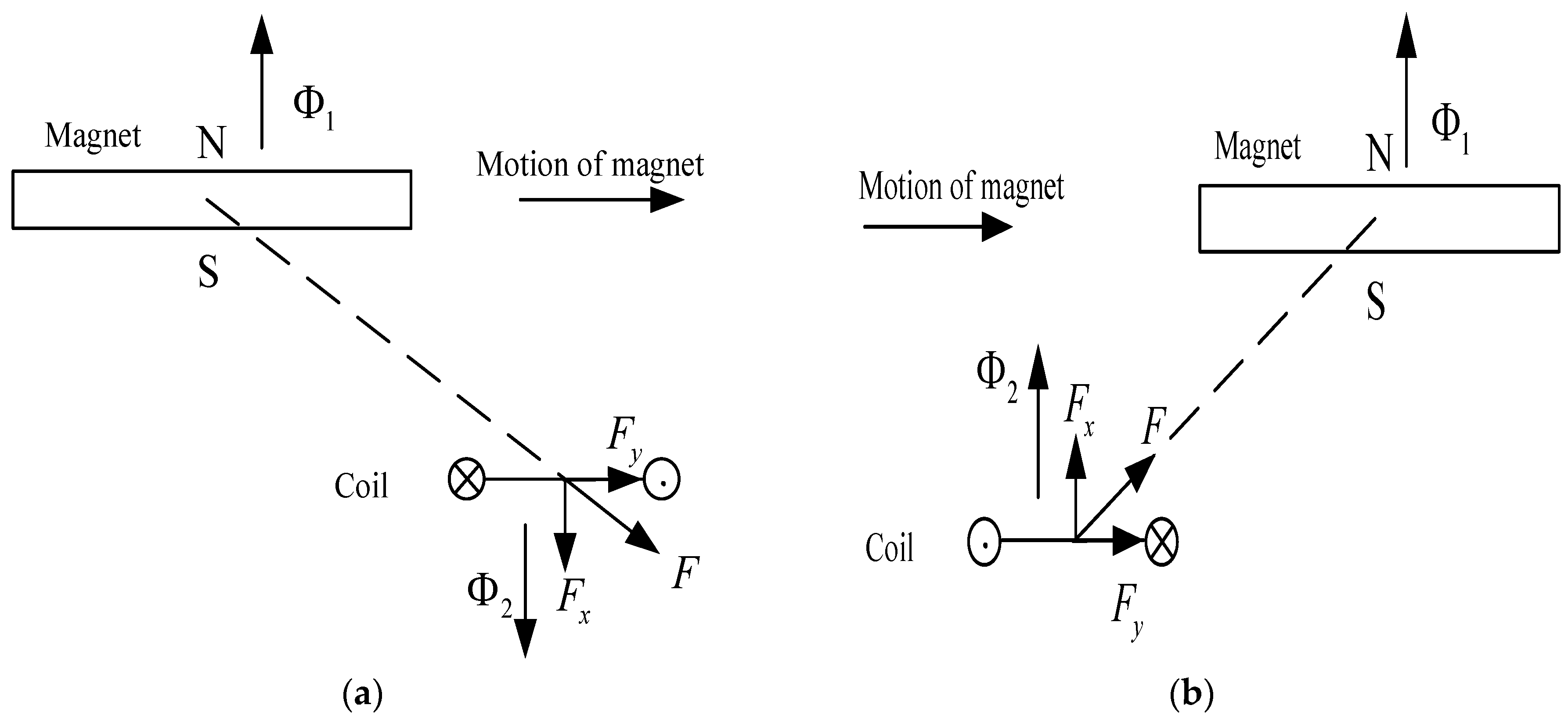
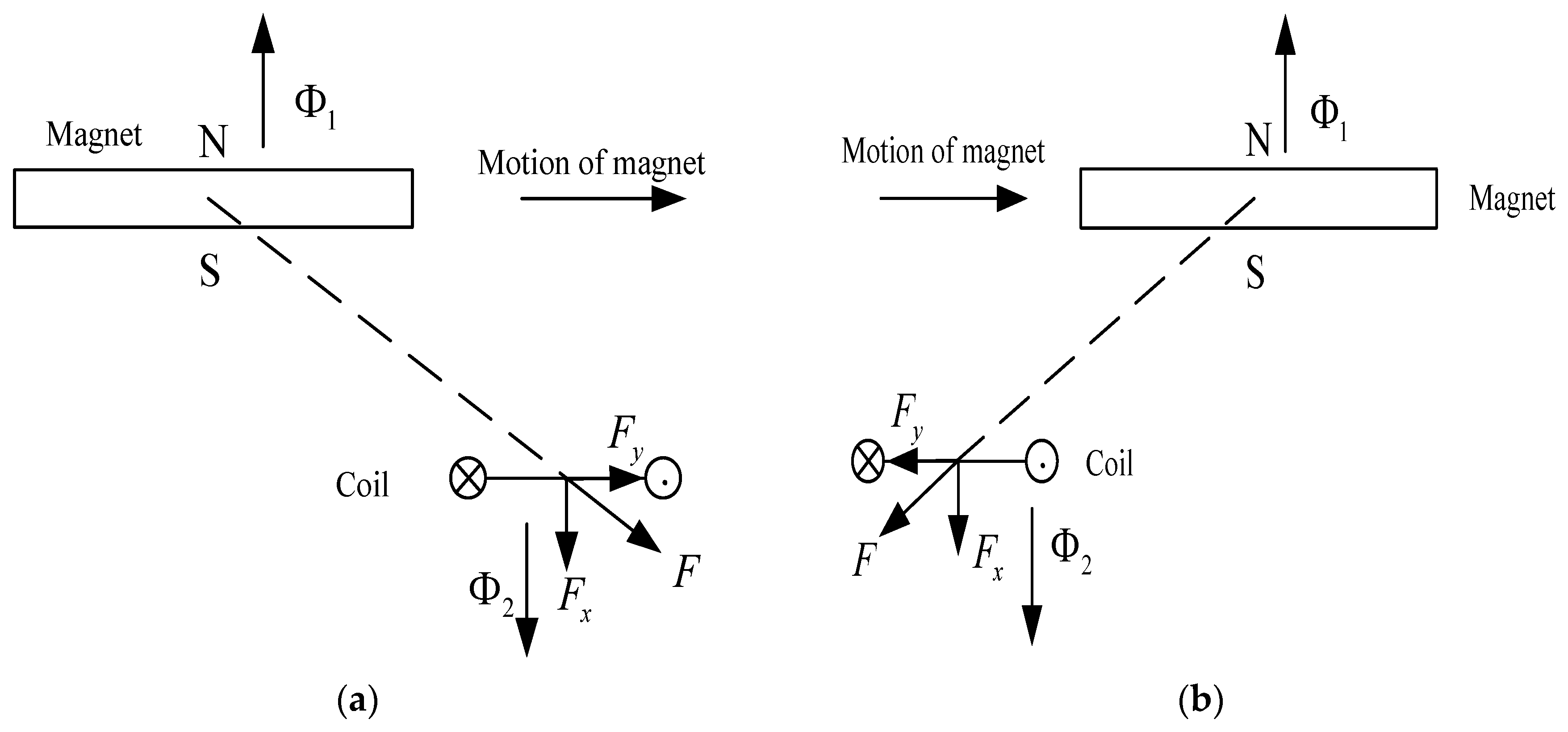
From the comparison of Figure 6 and Figure 7, it can be seen that both the induced current and the three magnetic forces have the same tendency in the calculation and the FEM simulation results, although there is a difference in amplitude values. The current and the forces have two impulses in the whole dynamic process, which are corresponding to the approaching and the leaving null-flux coil. The process of the magnet moving along the null-flux coil at low speeds can be simplified as Figure 8, and the south pole of the magnet faces downward. Figure 8a illustrates the process of magnet approaching the coil, and the stationary coil senses an increasing upward flux. Then an induced current in the coil will generate a flux opposing the flux change according to Lenz’s law, and the interaction can be taken as two magnets with the south poles facing each other. The time-dependent current and magnetic forces are related with the first impulse in Figure 6 and Figure 7. The magnet leaving the coil is illustrated in Figure 8b, and the flux linking the coil decreases. Similarly, an induced current in the coil with the opposite direction compared with Figure 8a is generated, and the interaction could be regarded as two magnets with the north and the south pole facing each other. The time-dependent current and magnetic forces during this period of leaving the coil are corresponding to the second impulse in Figure 6 and Figure 7. It can be seen that the second impulse is usually smaller than the first one because of the inductance in the coil. The average value of magnetic force during the whole moving period is decided by the integral of the time-dependent force. The two pulses in the levitation and the guidance forces have opposite directions, and the two pulses in the drag force have the same direction. To get a larger levitation force and a greater guidance force, it is helpful to increase the difference between the two opposite pulses in the levitation and the guidance forces. If the magnet is moving at a high speed, the process of moving along the coil could be simplified as shown in Figure 9.
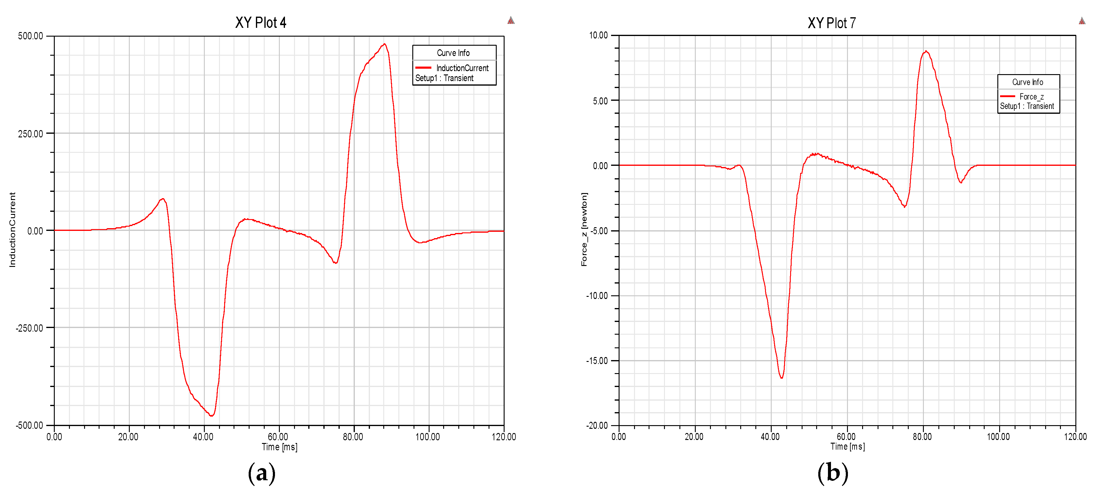
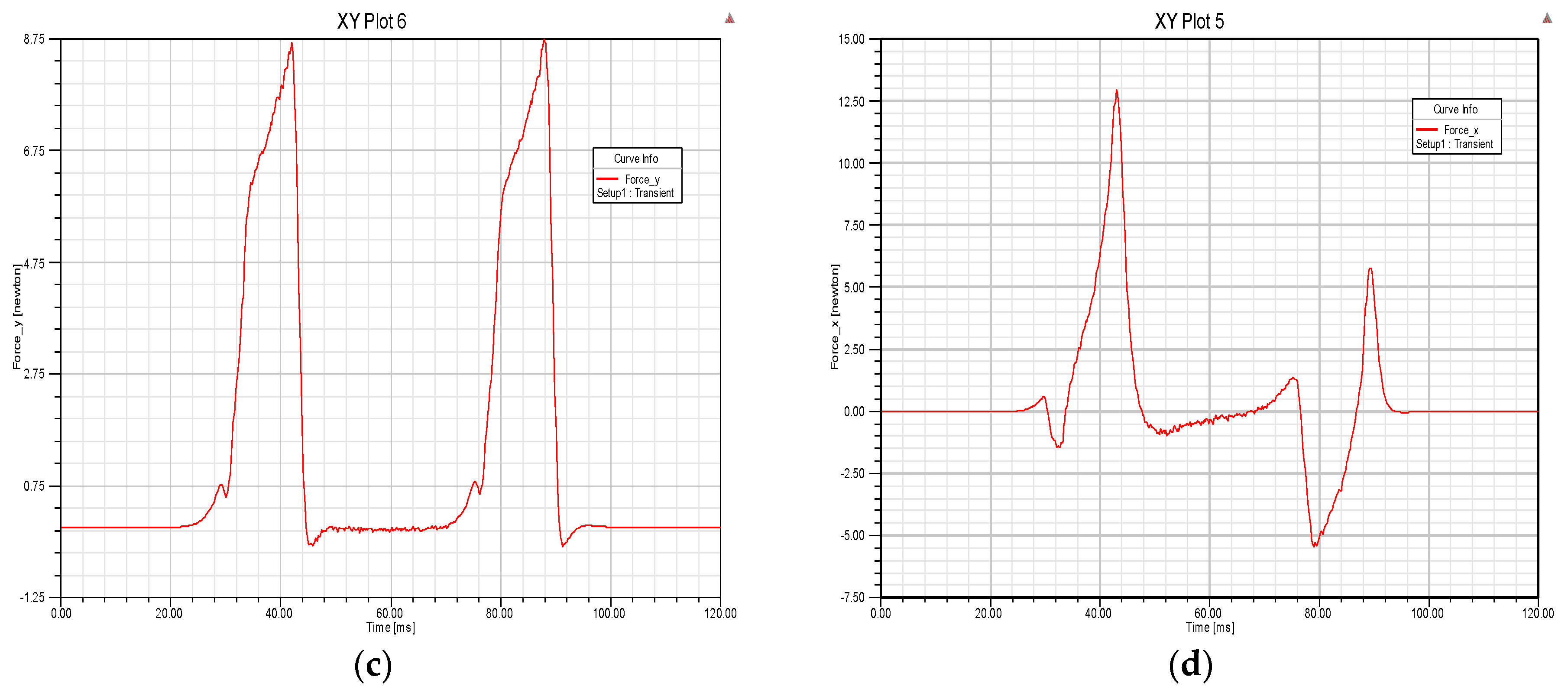
The process of approaching the coil in Figure 9a is the same as shown in Figure 8a, but the difference lies in the process of leaving the coil. Since the magnet is moving at a high speed, the traverse time of passing over the coil is shorter than the time constant of the coil. Then the induced current in the coil will have no time to change direction immediately, and this will lead to larger levitation and guidance forces and a smaller drag force. The simulation results at a speed of 30 m/s are shown in Figure 10. The induced current in coil is obviously larger than that at 10 m/s compared with Figure 7a. The differences between the two impulses in the levitation and the guidance forces become larger, which will generate bigger levitation and guidance forces. It can be seen that there are obvious and large negative impulses in Figure 10c compared with Figure 7c, meaning the time-average drag force will then become smaller. Therefore, a better levitation-drag ratio is achieved at higher speeds.
Apart from increasing the moving speed, a null-flux coil with a greater time constant is also applicable, and the results at speed of 10 m/s with coil of sectional area of 64 mm2 are shown in Figure 11. A larger sectional area will bring smaller resistance and a larger current, as illustrated in Figure 11a. The difference between two impulses in the levitation and the guidance forces become larger, and larger time-averaged levitation and guidance forces are generated.

3.4. Characteristics of Magnetic Forces

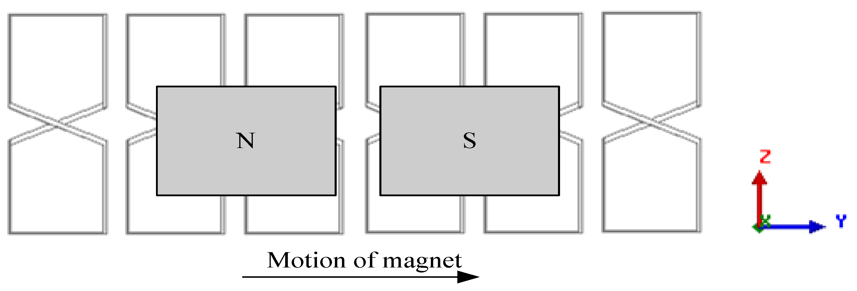
The characteristics of magnetic forces are studied using the structure of two magnets moving along a null-flux coil guideway at a constant speed, and the two permanent magnets are arranged in magnetic N and S poles for propulsion, as shown in Figure 12. The parameters of the model are listed in Table 2.

3.4.1. Effects of Speed

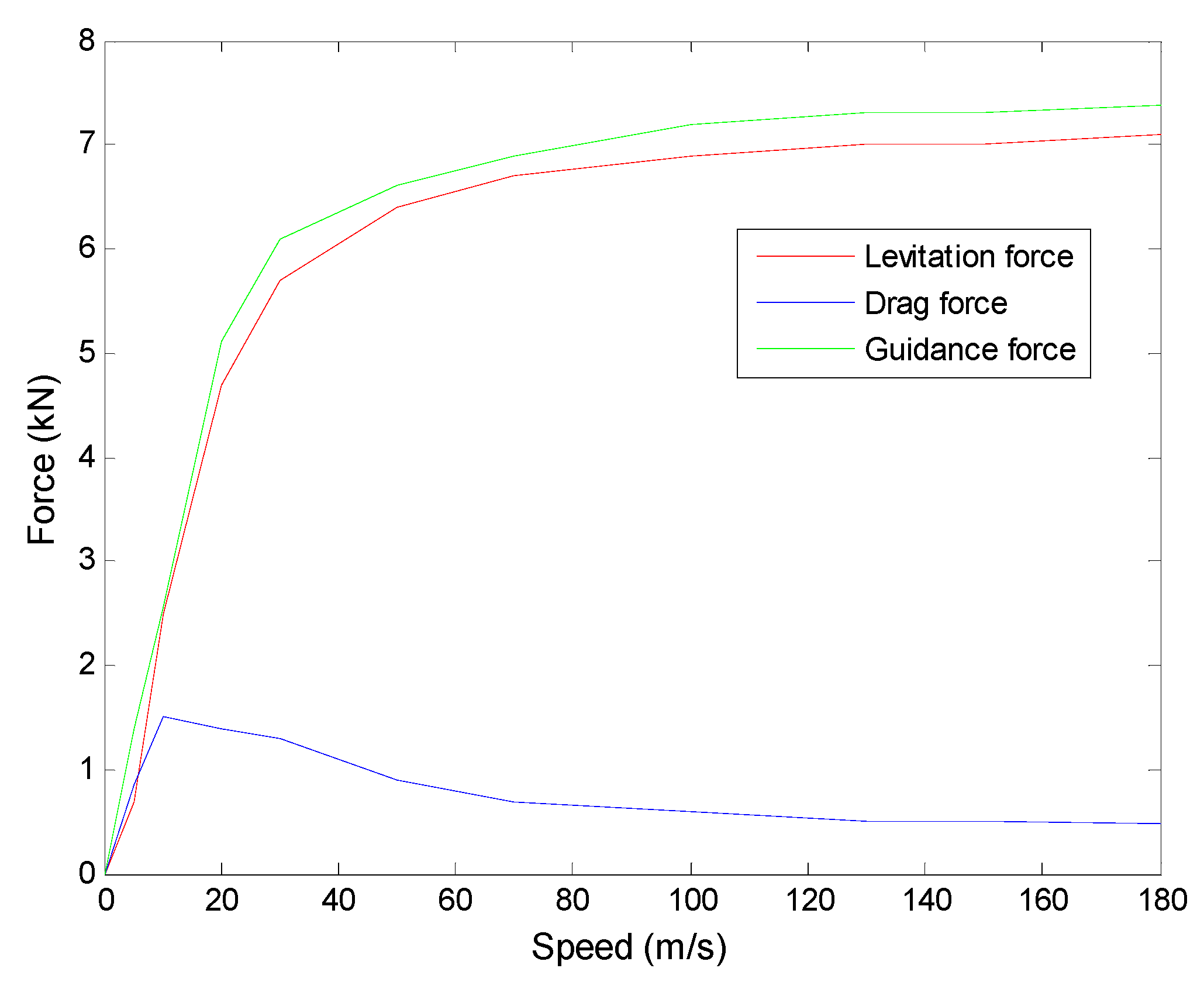
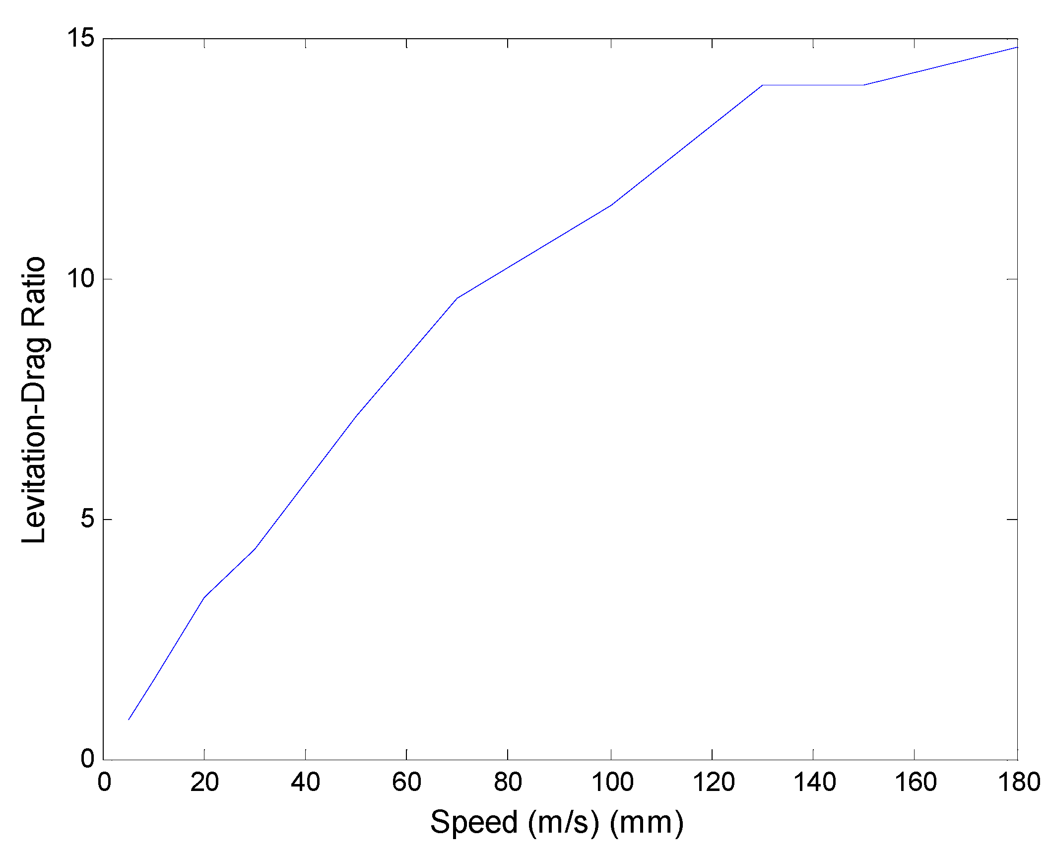
It is important to study the effects of moving speed on electromagnetic forces, since the EDS force is based on the relative motion between the coil and the magnet. The forces in three axes at different velocities with the structure parameters in Table 2 are shown in Figure 13. It can be seen that the levitation force and the guidance force increase first with initial low speeds, then they will keep relatively constant when reaching high speeds. This characteristic is beneficial for the evacuated tube high speed system, as the system could be levitated steadily in a vertical direction at high speeds beyond the critical point, and the relatively constant guidance force is helpful for the strength design of the vehicle body. The trend of the drag force is different from the other two forces. It increases at initial low speeds and will decrease with the increasing of speed after reaching the peak value. A larger ratio of the levitation and the drag forces is obtained at higher speeds, as shown in Figure 14.
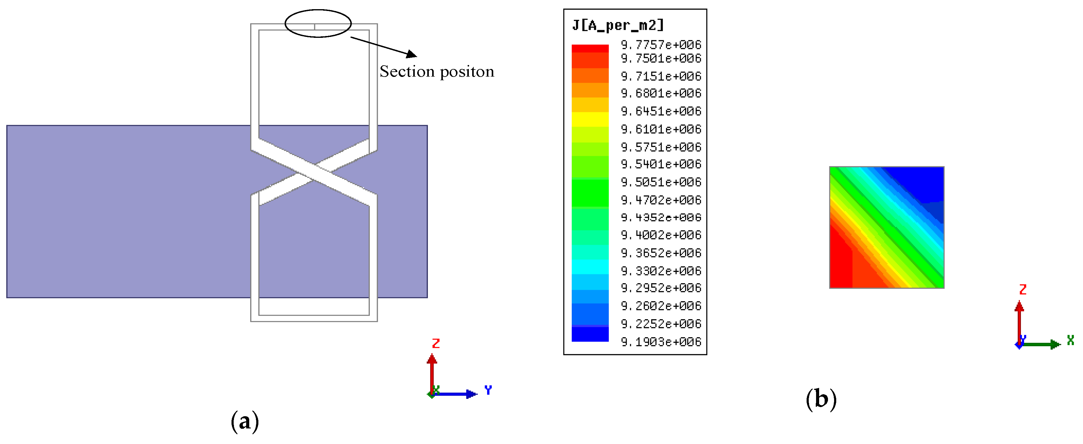
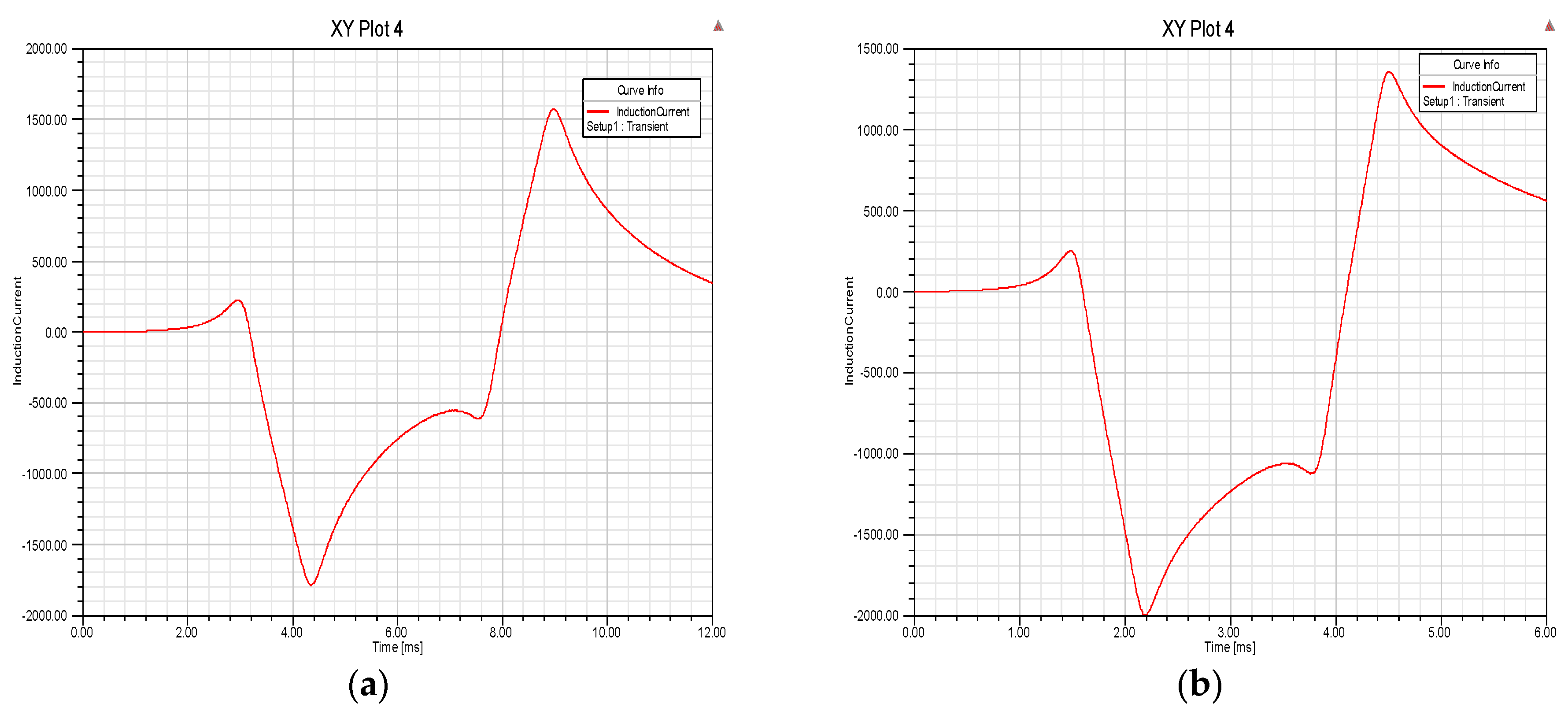
The relatively constant levitation and guidance forces can be qualitatively explained from the perspective of the eddy current. With the increasing of the magnet speed, the skin effect of the eddy current in the coil is more obvious and the eddy current distribution at speed of 100 m/s with parameters in Table 1 is illustrated in Figure 15. The strengthening skin effect will hinder the increasing of induced current at high speeds, and the change of eddy current at speeds of 100 m/s and 200 m/s is shown in Figure 16. It can be seen that the increasing of current amplitude at high speeds is minor compared with that at low speeds, and the gentle increase of the eddy current will lead to relatively constant levitation and guidance forces.

3.4.2. Levitation Working Point

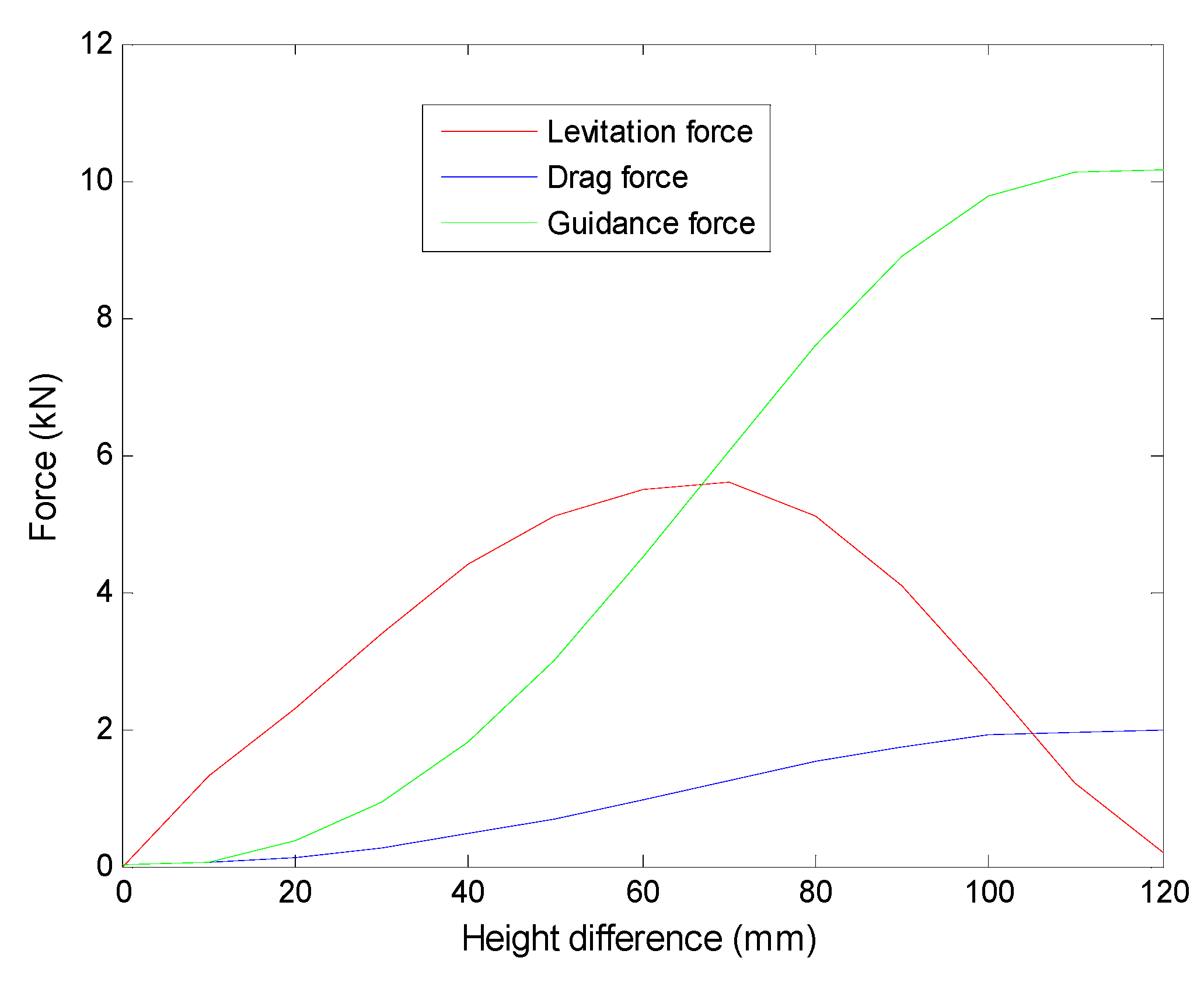
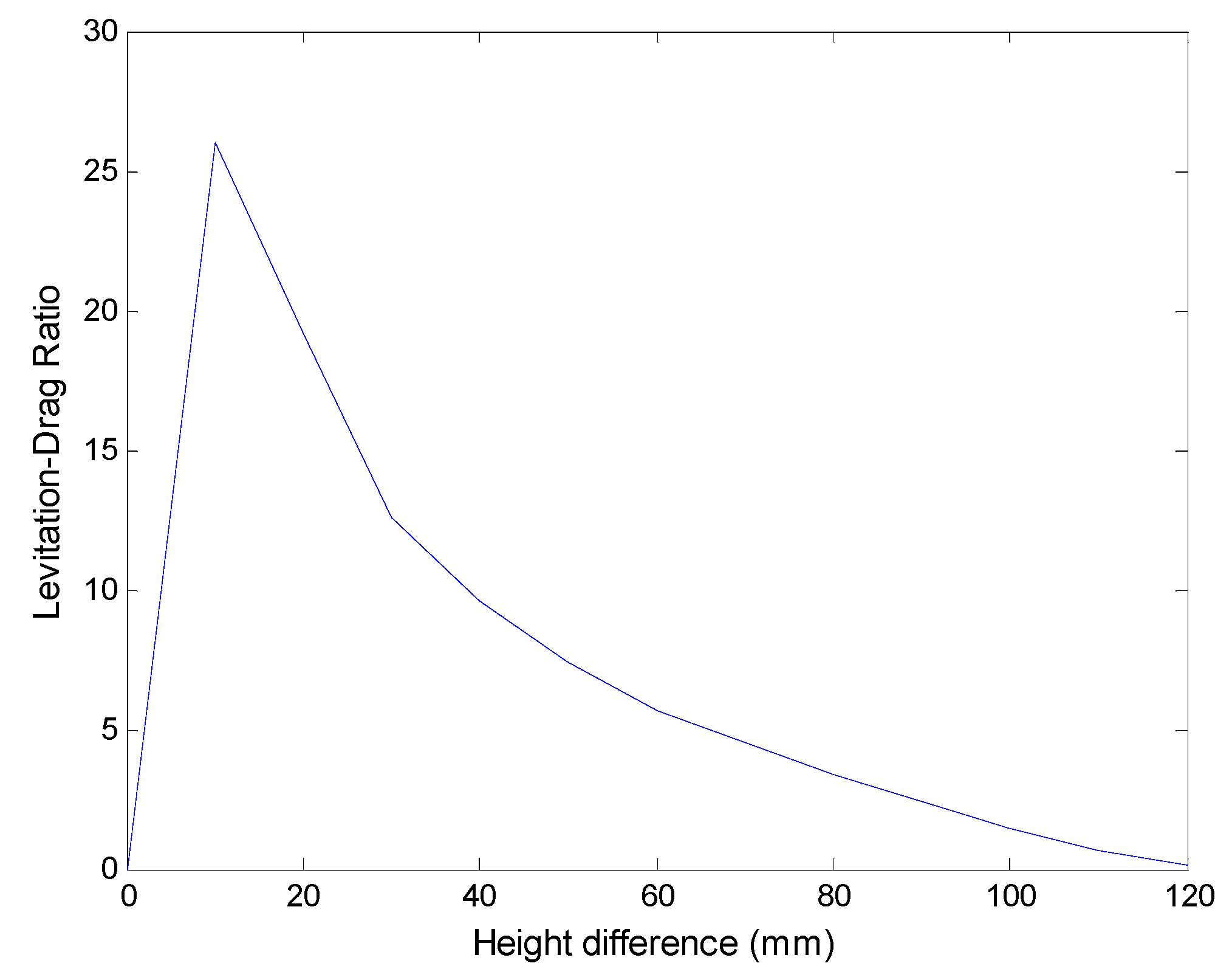
The height difference between the mid-lines of the magnet and the coil h is an important parameter in the EDS structure, which could be set as the levitation working point. The three magnetic forces as a function of height difference h are shown in Figure 17, and the calculation is conducted at the speed of 30 m/s. The levitation force increases first with the growing of the height difference h at the small value of h, and then will decrease after reaching the peak value at around 70 mm. The guidance and the drag forces have the different trend from the levitation force, as the values become larger with the increasing of h, and will keep relatively constant at large values of h. Figure 18 shows the dependence of the levitation-drag ratio on height difference h, and it can be seen that the ratio drops promptly as the height difference h increases after reaching a peak value. This implies that the levitation working point should be set at a small value of h to gain high system efficiency.
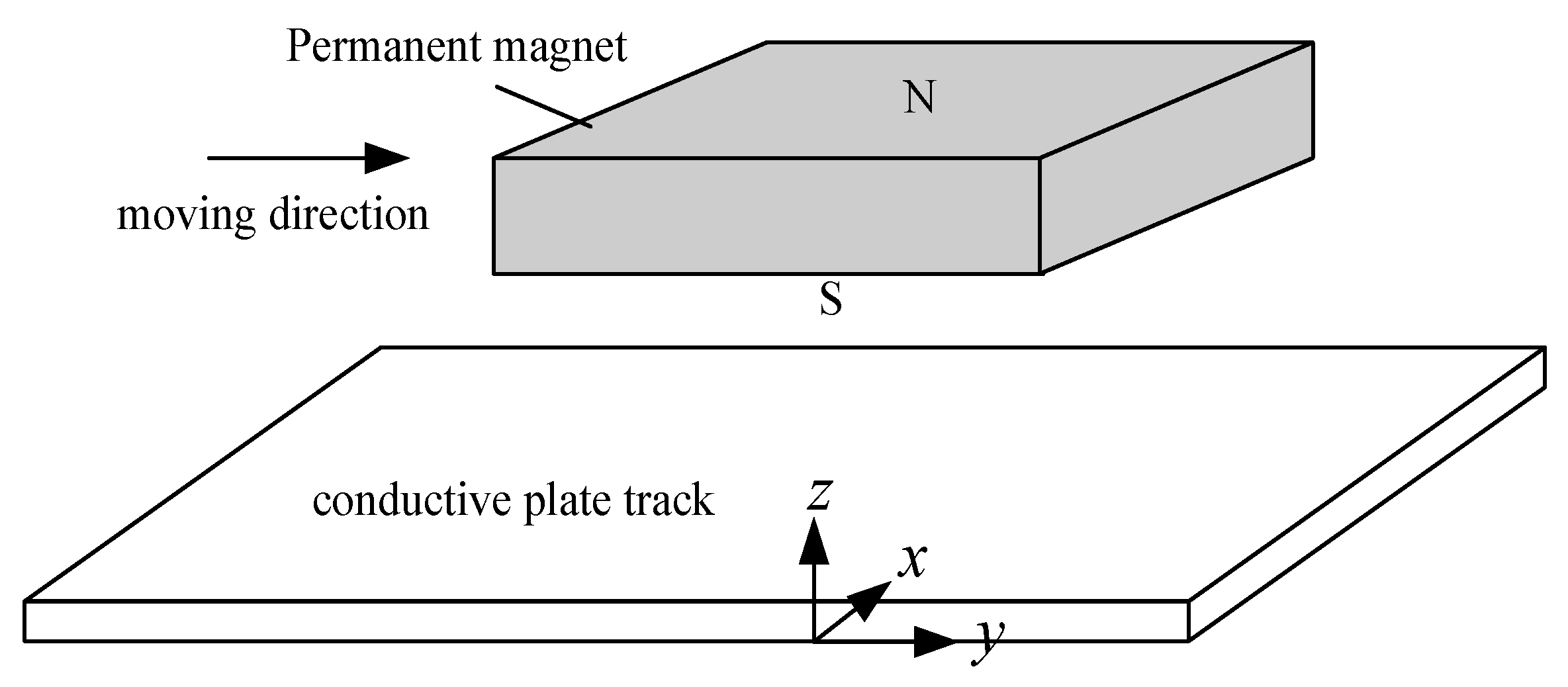
For comparison, the typical plate type EDS structure is shown in Figure 19, where the levitation and the drag forces are [26]:
F z = F L = B 0 2 w p τ μ 0 1 β η + 1 e 2 β h
F y = F D = B 0 2 w p τ μ 0 β η β η + 1 e 2 β h
where μ 0 is the vacuum permeability, B 0 is the flux density peak value of the permanent magnet array, w is the width of the permanent magnets, p is the pair of magnet poles, τ , is the pole pitch of permanent magnets, β = π / τ , h is the suspension gap, η = λ / π μ σ v is the skin depth, μ is the plate permeability, λ = 2 τ is the magnets wavelength, σ is the plate conductivity, and v is the magnet velocity. Then the ratio of levitation force and drag force is:
r L / D = 1 β η = 1 2 π π μ σ λ v .
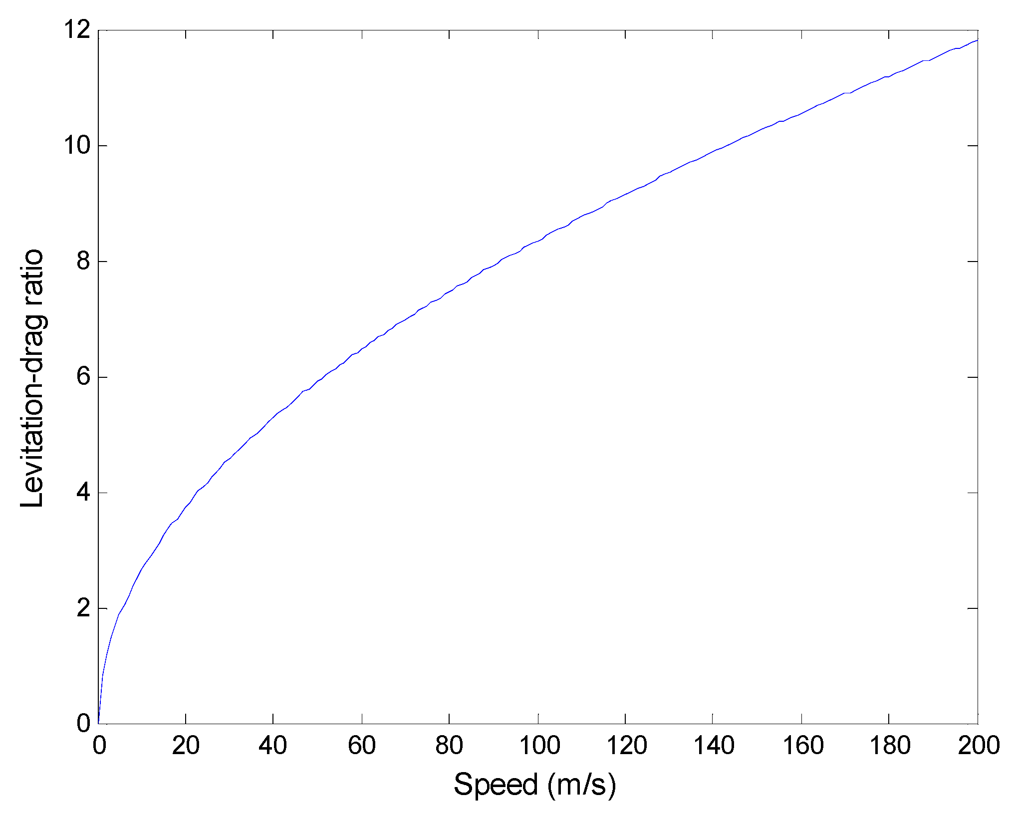
The parameters of the permanent magnet and the plate are set to be the same as that in Table 2, and the levitation-drag ratio as a function of magnet speed is shown in Figure 20. It can be seen that the ratio of plate type is 4.5 at speed of 30 m/s, however the figure eight coil structure could provide a much larger ratio value in a large domain of adjustable height differences from Figure 18, and the largest value could be beyond 25. A large levitation-drag ratio means a small drag force and heat loss in the guideway, and could decrease the burden of the propulsion system at the same time. The outstanding levitation-drag ratio is a critical advantage for a null-flux structure compared with a plate-type one, which is especially important in a ETT system since the heat radiation is not easy to address in an evacuated tube.

3.4.3. Guidance Stiffness

Guidance stiffness is an important characteristic index related with the lateral stability in a maglev system. The guidance stiffness of the system was researched by changing the lateral gap between the magnet and the coil, and the results are shown in Figure 21. When the gap from one side of the vehicle moves to 9 mm from 11 mm, then the other side will be 13 mm. The guidance force acting on the vehicle from both sides will be Δ F = 7.12   kN 6.32   kN = 0.8   kN and Δ F = 9.12   kN 8.12   kN = 1   kN at speeds of 30 m/s and 150 m/s, respectively. Then the stiffness 0.4 kN/mm and 0.5 kN/mm can be calculated. It can be seen that the stiffness at a low speed is relatively weaker than that at a high speed, and guidance auxiliary wheels could be designed in the system.

4. Conclusions

A null-flux coil EDS structure for high speed ETT was studied in this paper, and the whole system with functions of levitation, guidance and propulsion is presented. Both sides of the magnets were used in the propulsion and the levitation systems, which increases the utilization of the permanent magnets. The figure eight shaped null-flux coil suspension structure was adopted to provide a high levitation-drag ratio, compared with a plate-type EDS structure. The equivalent circuit method is applied to study the null-flux structure, and the validity of the theory is verified by comparing with the FEM results. The working principle of the null-flux coil structure is described, and the analysis on magnet moving along one coil shows that the magnet speed and the time constant of the coil have a great impact on the forces affecting the ETT. Then the characteristics of magnetic forces such as functions of the magnet speed, the levitation height, and the lateral gap were researched. The performances of the magnetic forces improve with the increasing speed, and the induced current will tend to be saturated at high speeds. The levitation height is a critical parameter for the EDS structure, as the levitation working point could be set at a small value to achieve a high levitation-drag ratio and at a relatively large value to get a large levitation force. Guidance stiffness was studied by changing the lateral gap, and the stiffness at a higher speed was stronger that that at a lower speed. The proposed structure with integration of propulsion, levitation and guidance is a promising option for application in a high speed ETT system, and future study will focus on the research of dynamic properties of the null-flux EDS structure during operation.

Author Contributions

Conceptualization, Z.G. and J.L.; methodology, D.Z.; software, Z.G.; formal analysis, Z.G.; investigation, D.Z.; writing—original draft preparation, Z.G.; writing—review and editing, D.Z.; supervision, J.L.; project administration, J.L.

Funding

This research was supported by the National Key R&D Program of China (No. 2016YFB1200601), and the Opening Foundation of the State Key Laboratory of Functional Materials for Informatics (No. SKL-2017-07).

Conflicts of Interest

The authors declare no conflict of interest.

References

  1. Zhai, M.; Long, Z.; Li, X. A New Strategy for Improving the Tracking Performance of Magnetic Levitation System in Maglev Train. Symmetry 2019, 11, 1053. [Google Scholar] [CrossRef]
  2. Bonfitto, A.; Tonoli, A.; Silvagni, M. Sensorless active magnetic dampers for the control of rotors. Mechatronics 2016, 47, 195–207. [Google Scholar] [CrossRef]
  3. Circosta, S.; Bonfitto, A.; Lusty, C.; Keogh, P.; Amati, N.; Tonoli, A. Analysis of a Shaftless Semi-Hard Magnetic Material Flywheel on Radial Hysteresis Self-Bearing Drives. Actuators 2018, 7, 87. [Google Scholar] [CrossRef]
  4. Galluzzi, R.; Amati, N.; Tonoli, A. Modeling, Design and Validation of Magnetic Hysteresis Motors. IEEE Trans. Ind. Electron. 2019. [Google Scholar] [CrossRef]
  5. Lee, H.W.; Kim, K.C.; Lee, J. Review of maglev train technologies. IEEE Trans. Magn. 2006, 42, 1917–1925. [Google Scholar] [CrossRef]
  6. Zhou, D.; Hansen, C.H.; Li, J. Suppression of maglev Vehicle-Girder Self-Excited vibration using virtual tuned mass damper. J. Sound Vib. 2011, 330, 883–901. [Google Scholar] [CrossRef]
  7. Yan, L. Suggestion for selection of Maglev option for Beijing-Shanghai high-speed line. IEEE Trans. Appl. Supercond. 2004, 14, 936–939. [Google Scholar] [CrossRef]
  8. Goddard, R.H. Vacuum Tube Transportation System. U.S. Patent US2511979A, 20 June 1950. [Google Scholar]
  9. Hyperloop Alpha. Available online: http://www.spacex.com/hyperloopalpha (accessed on 12 August 2013).
  10. Xu, J.; Geng, Q.; Li, Y.; Li, J. Design, Fabrication and Test of an HTS Magnetic Suspension Experimental System. IEEE Trans. Appl. Supercond. 2016. [Google Scholar] [CrossRef]
  11. Lee, C.Y.; Jo, J.M.; Han, Y.J. Design, Fabrication, and Operating Test of the Prototype HTS Electromagnet for EMS-Based Maglev. IEEE Trans. Appl. Supercond. 2012. [Google Scholar] [CrossRef]
  12. Bonfitto, A.; Castellanos Molina, L.M.; Tonoli, A.; Amati, N. Offset-Free Model Predictive Control for Active Magnetic Bearing Systems. Actuators 2018, 7, 46. [Google Scholar] [CrossRef]
  13. Davey, K. Analysis of an electrodynamic Maglev system. IEEE Trans. Magn. 1999, 35, 4259–4267. [Google Scholar] [CrossRef]
  14. Guo, Z.; Zhou, D.; Chen, Q.; Yu, P.; Li, J. Design and Analysis of a Plate Type Electrodynamic Suspension Structure for Ground High Speed Systems. Symmetry 2019, 11, 1117. [Google Scholar] [CrossRef]
  15. Long, Z.; He, G.; Xue, S. Study of EDS & EMS Hybrid Suspension System with Permanent-Magnet Halbach Array. IEEE Trans. Magn. 2011, 47, 4717–4724. [Google Scholar] [CrossRef]
  16. Hsu, Y.H.; Langhom, A.; Ketchen, D.; Holland, L.; Minto, D.; Doll, D. Magnetic levitation upgrade to the Holloman High Speed Test Track. IEEE Trans. Appl. Supercond. 2009, 19, 2074–2077. [Google Scholar] [CrossRef]
  17. Okubo, T.; Ueda, N.; Ohashi, S. Effective Control Method of the Active Damper System against the Multidirectional Vibration in the Superconducting Magnetically Levitated Bogie. IEEE Trans. Appl. Supercond. 2016. [Google Scholar] [CrossRef]
  18. Deng, Z.; Zhang, W.; Zheng, J.; Wang, B.; Ren, Y.; Zheng, X.; Zhang, J. A High Temperature Superconducting Maglev-Evacuated Tube Transport (HTS Maglev-ETT) Test System. IEEE Trans. Appl. Supercond. 2017, 27, 6. [Google Scholar] [CrossRef]
  19. Ding, J.; Yang, X.; Long, Z.; Dang, N. Three Dimensional Numerical Analysis and Optimization of Electromagnetic Suspension System for 200 km/h Maglev Train Considering Eddy Current Effect. IEEE Access 2018, 6, 1547–1555. [Google Scholar] [CrossRef]
  20. Du, J.; Ohsaki, H. Numerical analysis of eddy current in the EMS-Maglev system. In Proceedings of the 6th International Conference on Electrical Machines and Systems, 2003. ICEMS 2003, Beijing, China, 9–11 November 2003. [Google Scholar]
  21. Abdelrahman, A.S.; Sayeed, J.; Youssef, M.Z. Hyperloop transportation system: Analysis, design, control and implementation. IEEE Trans. Ind. Electron. 2018, 65, 7427–7436. [Google Scholar] [CrossRef]
  22. Ji, W.Y.; Jeong, G.; Park, C.B.; Jo, I.H.; Lee, H.W. A study of Non-Symmetric Double-Sided linear induction motor for Hyperloop all-in-one system (Propulsion, Levitation, and Guidance). IEEE Trans. Magn. 2018. [Google Scholar] [CrossRef]
  23. Danby, G.T.; Powell, J.R. Design Approaches and Parameters for Magnetically Levitated Transport Systems: Superconductivity and Its Applications; Elsevier Science Publishing Co., Inc.: London, UK, 1988; pp. 318–342. [Google Scholar]
  24. He, J.; Coffey, H.T. Magnetic damping forces in figure-eight-shaped null-flux coil suspension systems. IEEE Trans. Magn. 1997, 33, 4230–4232. [Google Scholar] [CrossRef]
  25. He, J.; Rote, D.M.; Coffey, H.T. Electrodynamic Forces of the Cross-Connected Figure-Eight Null-Flux Coil Suspension System. In Proceedings of the International Conference On Magnetically Levitated Systems and Linear Drives, Argonne, IL, USA, 19–21 May 1993. [Google Scholar]
  26. Post, R.F.; Ryutov, D. The Inductrack concept: A new approach to magnetic levitation. In Office of Scientific & Technical Information Technical Reports; Lawrence Livermore National Lab.: Livermore, CA, USA, 1996. [Google Scholar] [CrossRef] [Green Version]
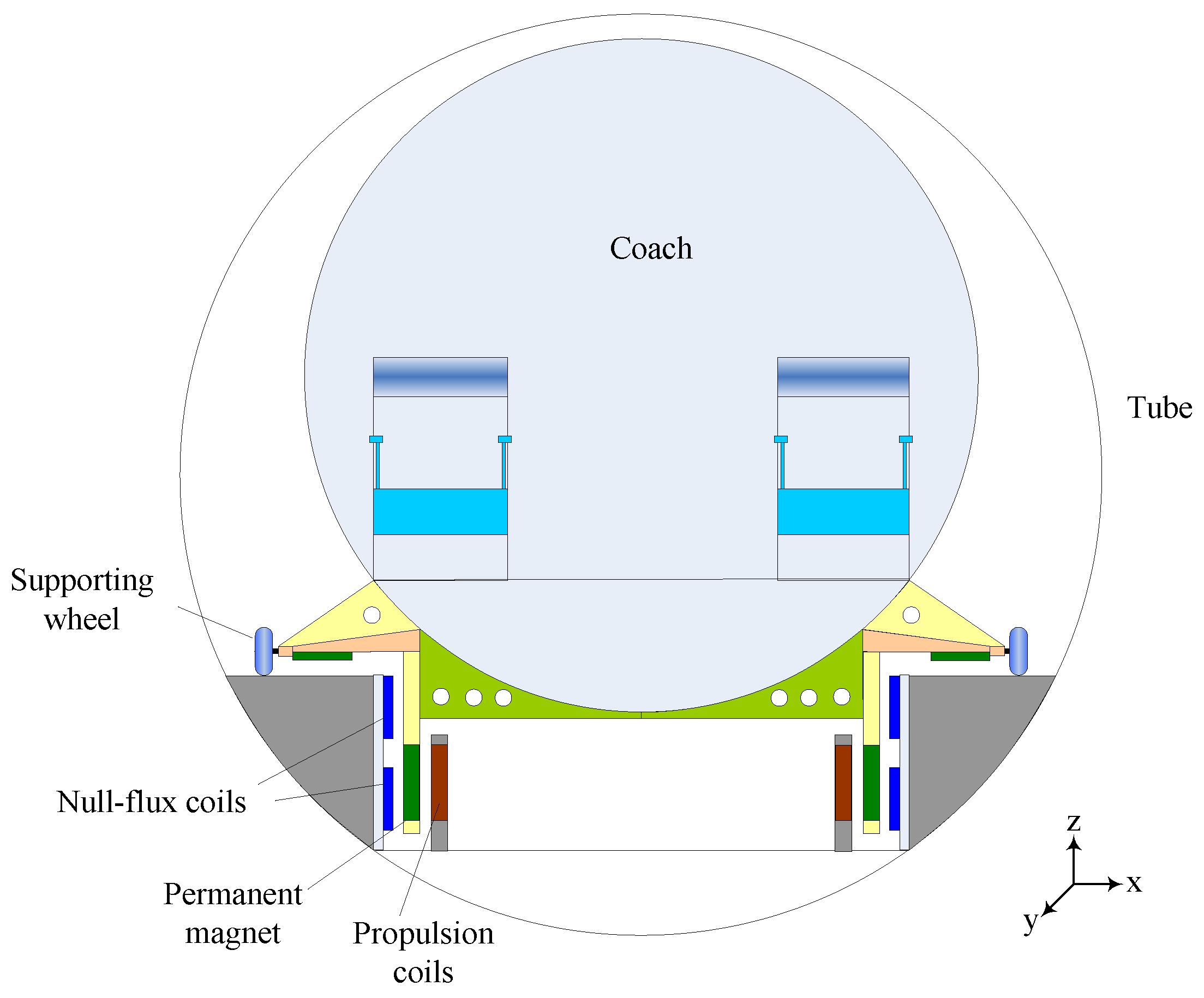
Figure 1. Proposed structure of an evacuated tube transportation (ETT) system.
Symmetry 11 01239 g001
Figure 2. Illustration of the interaction between the magnet and the coil.
Symmetry 11 01239 g002
Figure 3. Equivalent circuit of null-flux coil.
Symmetry 11 01239 g003
Figure 4. Flow chart of the force calculation process.
Symmetry 11 01239 g004
Figure 5. Finite element analysis (FEM) simulation model.
Symmetry 11 01239 g005
Figure 6. Calculation results based on dynamic circuit theory at speed of 10 m/s, (a) Induced current in null-flux coil; (b) Levitation force; (c) Drag force; (d) Guidance force.
Symmetry 11 01239 g006
Figure 7. FEM simulation results at speed of 10 m/s, (a) Induced current in null-flux coil; (b) Levitation force; (c) Drag force; (d) Guidance force.
Symmetry 11 01239 g007
Figure 8. Magnet moving along the coil at a low speed, (a) Approaching the coil; (b) Leaving the coil.
Symmetry 11 01239 g008
Figure 9. Magnet moving along the coil at a high speed, (a) Approaching the coil; (b) Leaving the coil.
Symmetry 11 01239 g009
Figure 10. Simulation results at speed of 30 m/s, (a) Induced current in null-flux coil; (b) Levitation force; (c) Drag force; (d) Guidance force.
Symmetry 11 01239 g010
Figure 11. Simulation results at speed of 10 m/s with coil of 64 mm2, (a) Induced current in null-flux coil; (b) Levitation force; (c) Drag force; (d) Guidance force.
Symmetry 11 01239 g011aSymmetry 11 01239 g011b
Figure 12. Model of magnets moving along null-flux coil guideway.
Symmetry 11 01239 g012
Figure 13. EDS forces as a function of magnet velocity.
Symmetry 11 01239 g013
Figure 14. Levitation drag ratio over magnet velocity.
Symmetry 11 01239 g014
Figure 15. Distribution of eddy current in the section of the null-flux coil, (a) The position of section in the coil; (b) Distribution of eddy current in the section of Figure 15a.
Symmetry 11 01239 g015
Figure 16. Eddy current at speeds of 100 m/s and 200 m/s, (a) 100 m/s; (b) 200 m/s.
Symmetry 11 01239 g016
Figure 17. EDS forces as a function of height difference h (speed 30 m/s).
Symmetry 11 01239 g017
Figure 18. Levitation-drag ratio as a function of height difference h at speed of 30 m/s.
Symmetry 11 01239 g018
Figure 19. Typical plate type EDS structure.
Symmetry 11 01239 g019
Figure 20. Levitation-drag ratio vs. magnet speed (plate type EDS).
Symmetry 11 01239 g020
Figure 21. Guidance force as a function of the gap between the magnet and the coil.
Symmetry 11 01239 g021
Table 1. Parameters of the FEM model in Figure 5.
VariableValueUnit
Length of magnet (axis Y)460mm
Height of magnet (axis Z)210mm
Thickness of magnet (axis X)20mm
Remanence of permanent magnet (PM)1.33T
Coercivity of PM962kA/m
Length of null-flux coil137mm
Height of null-flux coil365mm
Sectional area of null-flux coil16mm2
Height of gap between the upper and the lower loops30mm
Resistivity of the coil (Cu)1.75 × 10⁻⁸ Ω · m
Lateral gap between the coil and the magnet (axis X)10mm
Height difference between the mid-lines of the magnet and the coil (axis Z)70mm
Speed of the magnet (axis Y)10m/s
Table 2. Parameters of the model in Figure 12.
VariableValueUnit
Length of PM (axis Y)550mm
Height of PM (axis Z)220mm
Thickness of PM (axis X)50mm
Pole pitch of magnets600mm
Remanence of PM1.33T
Coercivity of PM962kA/m
Length of null-flux coil340mm
Height of null-flux coil450mm
Height of gap between the upper and the lower loops35mm
Sectional area128mm2
Gap between the neighboring coils45mm
Resistivity of the coil (Cu)1.75 × 10⁻⁸ Ω · m
Height difference between the mid-lines of the magnet and the coil (axis Z)70mm
Lateral gap between the coil and the magnet (axis X)15mm