1. Introduction
Accidents associated with natural events or human actions are a common cause of hydraulic system failure. As a result, unwelcome accidents lead to enormous damage, the destruction of networks and the abruptly stoppage of supply. These events can also be classified as external or internal. External ones may result from extreme events (
i.e., such as storms, floods, landslides, earthquakes, sudden releases or ruptures) and can be a consequence of structural characteristics, maintenance state, or hydraulic operation devices [
1]. Pipe systems, especially those installed above the ground, are under relevant dynamic forces during the occurrence of transients (water-hammer). When these forces are associated with system movement, a fluid structure interaction is generated, which means that the liquid and the pipe must be analysed as a whole [
2]. Transient pressures and dynamic vibrations generated by a water-hammer or by the closing of a valve (internal causes) lead to new loads on the system such as internal and external pressures created by the soil and/or through the pipe supports [
3].
The vulnerability and susceptibility of a pipeline system can be better understood after the occurrence of accidents. Such hazards may be associated with several factors causing numerous problems, particularly when they are neglected during different design stages: project concept, sizing, implementation and operation [
4,
5,
6,
7].
Extreme transient pressure variations may cause deformations and displacements in pipes which, in turn, will interact with the hydraulic system, modifying its own active loading and, consequently, its reaction [
8,
9], resulting in vibration or resonance phenomena that may cause the system to fail. As a consequence, the vibrations can cause the structure to rupture due to fatigue or through the increase of structural deformations. Hence, the structural response under different load combinations is provided by using an FEM representing the characteristics involved in hydraulic systems exposed to external and internal load vibrations [
10]. The behaviour of the fluid and the structure can be studied as a whole, with a structural model, if appropriate load combinations are adopted. This approach allows the possible consequences to be shown in terms of displacements and the vulnerability of the pipeline and its supports.
In the classic theory of finite elements it is assumed that movements and deformations are small and the material has a linear elastic behaviour. In some cases this condition cannot be satisfied, leading to the inclusion of non-linearity action/reaction to the model [
11]. In this work, the model Robot Autodesk (Autodesk, Inc., San Rafael, CA, USA) is used to study the behaviour of a suspended pipeline under different loads, using nonlinear theory. The results obtained by the computational simulation allow us to verify the adequacy of the supports’ design in a presence of transient phenomena. The importance of detailed studies of identical system behaviour for different loads in the infrastructure design is also emphasized.
2. Background
The design of a suspended pipeline requires two alternative structure solutions: pipelines supported by auxiliary structures or self-supporting pipelines. In this research, a real case of auxiliary structures supporting a pipeline (
i.e., pipeline bridge) is studied. The preferred conceptual design of a pipe bridge consists of a straight configuration that can use a restrained mechanical joint ductile iron pipe (DIP) or a butt welded steel pipe with a pipe expansion joint, on a roller system, allowing the pipe to act independently of the superstructure [
12]. This scenario is considered the ideal case because it is free of fittings and minimizes pipe joint deflections, which create thrust forces [
13].
A stress analysis of the pipelines needs to be conducted to verify the integrity of the suspended structure, as the expected pressure extremes which ensure the applied pre-tension guaranteed that the columns remain in tension [
14].
Many pipe failures in natural events have resulted from the sliding, rocking or overturning of large equipment to which the pipe is attached. During these events, the tanks may twist and slide in the concrete saddles, resulting in ruptures. It is therefore important to verify the adequacy of the anchorage equipment and tie-downs as part of design or retrofit of pipeline systems [
15]. The same type of failure can take place when a pipe is connected to two separate structures (e.g., vertical pipe supports and lateral bracing).
The vibration caused by external or internal forces is transmitted to the pipe, and if the pipe is too stiff, this motion may cause the pipe to fail. Some building codes advocate the use of “flexible assemblies” to absorb differential building motion, such as placing a flexible assembly in the pipe where it crosses building joints [
16]. However, most pipe spans are sufficient flexibles to absorb this differential movement. Otherwise, unless required by a building code, it is prudent to avoid placing these flexible assemblies at the preliminary design stage and only use them if there is no other alternative solution confirmed by detailed stress analysis [
17].
In a suspended pipeline, this system can be idealized as continuous beams spanning lateral braces [
18]. Commonly, vertical supports for gravity and operational loads are adequate to resist the vertical seismic forces, since the vertical component of seismic force is often lower than other vertical loads [
19]. However, where a support resists to the vertical component of a lateral or longitudinal brace force, it should be designed explicitly to resist all applied forces, such as transient events.
3. Formulation of the Problem
3.1. Description of the Accident
Knowledge on the effect of a flowing mass on the dynamic response of suspended pipelines simultaneously under moving loads is still lacking from the point of view of structural design. The dynamic stability of suspension structures has been the focus of several studies [
20,
21,
22]. However, few studies has been focused on the effect of interaction between fluid and structure, especially under different actions of the pipeline’s suspension with pressurized flows. The purpose of this research is to investigate the dynamic effects involved in a suspended pipeline bridge by combining the maximum overloading and water-hammer phenomena.
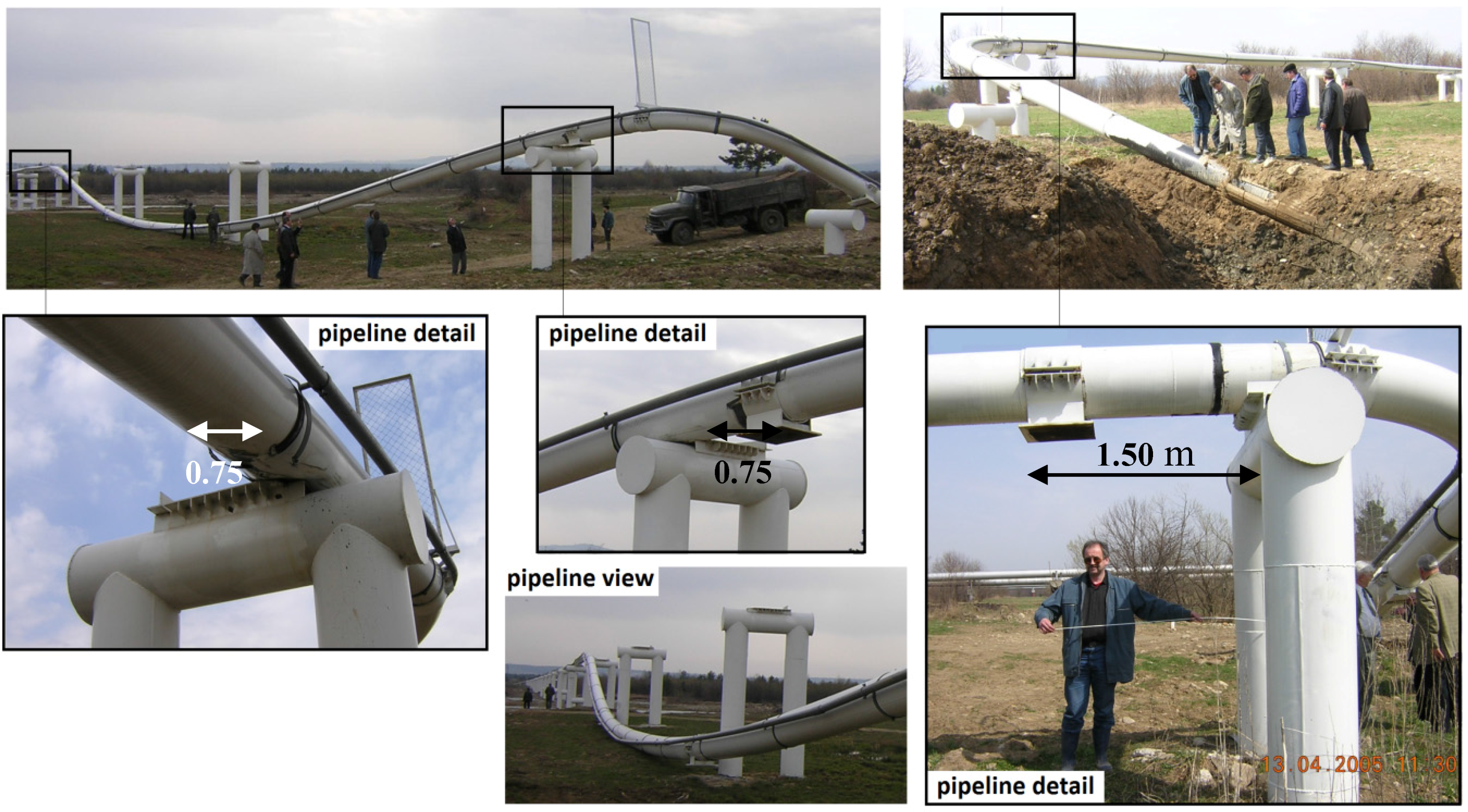
The case study is based on an accident that happened in Ukraine 2005, where due to water-hammer phenomena the pipeline, used to transport oil to refineries, was set in motion, bent at the opposite ground entrance section
(i.e., displacements in upper and transverse directions) and thrown from its supports. The measured pressures registered values higher than 10 MPa. This overpressure was responsible for the failure at an underground section,
i.e., 50 m from the surface section of the pipeline to the source (
Figure 1).
The material of the pipeline is steel and has a nominal diameter (ND) of 500 mm. The steel supports, fixed in concrete footings, have U-configuration with maximum spans of 15 m. After the water hammer phenomena, the pipeline moved about 1.50 m in the pipe direction (axis-x) and 0.75 m in the transverse direction (axis-y).
This accident highlights the importance of assessment of factors which cause instability and lead to eventual rupture, with analyses of the safety condition of strategic pipeline systems under pressure, mainly due to effects of water-hammer and earthquakes responsible for the rupture and fatigue of the structure. In the case of sudden changes (i.e., transient events, earthquakes), a pipeline’s design rarely remains in good performance conditions. Thus, the vulnerability of the pipeline system to transient actions is analysed, through an advanced FEM structural analysis (Robot Autodesk), to simulate the consequences of a water-hammer in terms of displacements and loads in the pipes and support structures. Subsequently, comparisons are made between the results obtained at the accident and in simulations to better understand the causes and effects herein reported.
3.2. Definition of Physical Characteristics
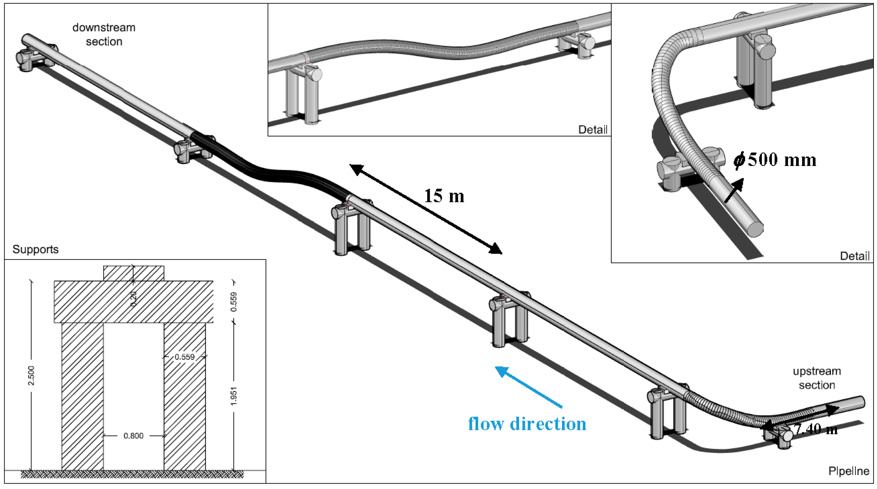
The system, based on the real case, is a pipeline with a total length of 74 m, composed of 6 steel supports with a 500 mm internal diameter (
Figure 2). Three of the 6 supports are 3 m in height with a 15 m span, followed by 2 supports 1.20 m in height in the downstream section (
Figure 2). The remaining upstream section has spans of 5 (
i.e., in the bend) and 7.4 m (
i.e., in the initial section). The supports consist of 3 steel tubes with wall thickness of 50 mm. The pipeline is attached to two separate structures forming the supports. The pipeline has a thickness of 26.2 mm.
The chapters below present finite element results of the stresses and displacements in the pipeline and in supports due to internal pressure under the combination of the water-hammer event. Two combinations and nonlinear effects associated with each load are also studied separately. The material used for the pipeline, according to specifications ANSI/ASME B.31.4, is carbon steel API-5L Gr. B, with the characteristics presented in
Table 1.
The selected material was estimated based on the maximum pressure achieved during the accident. Thus, Sch/serie 60 was chosen since the maximum allowable operating pressures is higher than that registered in situ and because the overpressure induced by the water-hammer did not cause the rupture of the pipeline.
4. Structural Model
4.1. Introduction
In this research, the Autodesk Robot Structural Analysis Professional 2015 program was used to determine the static and dynamic performance of structural systems and analyse the linearity and non-linearity of the system behaviour. This is a program for calculation by finite element structures that includes a wide range of design codes of all types of metal and concrete structures, with the possibility of contemplating other structural materials [
24].
For different structures, the beam element is a slender structural member that offers resistance to forces and bending under applied loads [
25]. It is represented by line elements used to create a 1D idealization of a 3D structure, and is computationally more efficient than solids or shells [
18].
The use of a beam element is highly applicable to most beam structures, e.g., bridges, roadways, building constructions, and people movers (railcars, trams and buses), since they support linear and nonlinear analyses, including plasticity, large deformations, and nonlinear collapse [
26]. It is easy to use especially when:
the length of the element is much greater than the width or depth;
the element has consistent cross-sectional properties;
the element must be able to transfer moments;
the element must be able to handle a load distributed across its length.
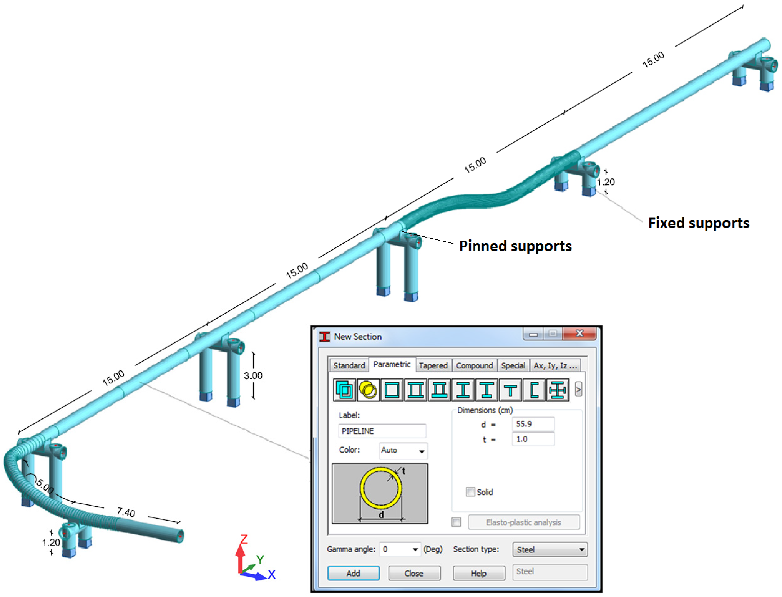
Thus, to reproduce the accident, the structure was modelled using beam elements. All combinations were performed using the European section database (EURO code). The geometry was defined in Autocad and then exported to Robot, where the boundary conditions were set. Herein, fixed supports are assigned to the two pillars of the 6 support structures (
Figure 3). The transfer of forces, induced by the pipeline and the fluid to the support, are made by intermediate connectors welded to the steel beam tube.
4.2. Design Considerations
4.2.1. Load Combinations
The primary pipe loading on the bridge structure is the pipe dead load which includes the weight of the pipe, the water inside the pipeline, pipe accessories (i.e., expansion joints, couplings), and the pipe support system. Other loads that should be considered are wind, earthquake and impact. In the present study, only an internal load is evaluated: the water-hammer phenomenon.
In limit states, the loads are multiplied by safety factors and grouped into load combinations. For different codes (e.g., BSI 8010 UK; ASME B31.4 US; ISO 13623), different combinations of loads are established. The general requirement is that the defined load combination should be appropriate to the ultimate limit state. The Canadian code CSA-Z662 (1996) uses the following general equation for calculating the load combinations (
i = 1, 2, 3, ...):
where, ∝ = safety factor class;
loading factors (
Table 2) for
= permanent loads (
i.e., weight of the water inside the pipeline);
= operational loads (overloading,
i.e., internal pressure during normal conditions);
= environmental loads (
i.e., seismic load);
= live loads (
i.e., transient events).
For each load combination, its effects are calculated as the level of stress and deformation. The resulting value of these effects is compared with the threshold value, to determine if the limit state is respected.
The safety factor class depends on the risk to which the structure is subjected. In the case of pipelines the safety factor is 2.0. According to the case study, two types of combinations were selected and applied as presented in
Table 3.
4.2.2. Internal Loads
The first simulation is performed for combination ULS1 (without transient and natural events), where the overloading is the internal pressure, during normal conditions, plus 2000 N applied in the vertical direction, for pipelines located 3 m from the ground according to [
28]. In order to verify whether the pipeline bridge is designed appropriately, it is necessary to satisfy the following conditions:
the maximum pipeline bending stress, due to pressure, weight and other sustained mechanical loads, is below the ultimate material load limits, given by [
29]:
where
= length between supports (m);
= moment of resistance (cm
4);
= total distributed loads (N/m);
= total concentrated loads (N), in this case
;
= overload imposed at mid-span;
the maximum deflection at mid-span is below 25 mm for the limit value of pipelines with diameters higher than 100 mm [
29], calculated as:
where
= elastic modulus (MPa);
= moment of inertia of the pipeline cross section (cm
4);
the maximum stress due to internal pressure (
) is below the acceptable stress of the pipe (
i.e.,
(
Table 1)):
and the total longitudinal load stresses (
) (
i.e., pressure, weight, overloading) is below
:
the vertical or lateral motion is below to the limit motion given by [
29]:
where
= maximum displacement (mm);
= elastic modulus (kgf/cm
2).
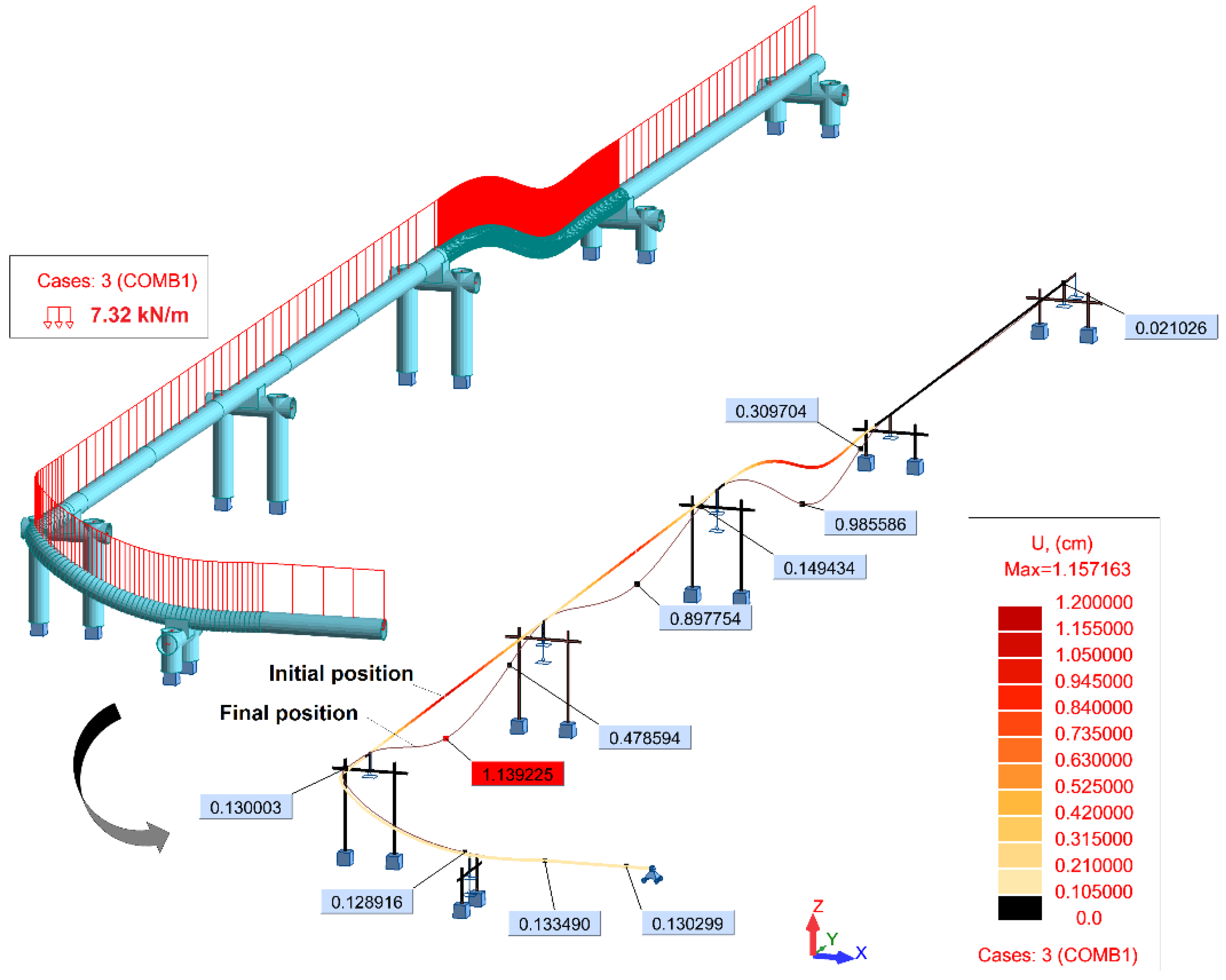
For combination ULS1, all the conditions are verified. The maximum deflection Equation (3) obtained at mid-span is ~11.5 mm (
Figure 4), which is below the allowable limit value.
4.2.3. Transient Loads
For combination ULS3, the effects of pressure, weight, other sustained loads and occasional loads including earthquakes shall meet the requirements of Equation (7):
where
= 1.2 for occasional loads acting less than 1% of the operating period;
= stress due to occasional loads, such as thrusts from pressure, flow transients and earthquakes.
The other assumption is related to the critical pressure (
i.e., burst pressure) [
29]:
where
the elastic modulus of steel,
the poisson modulus,
and
the outer diameter and the thickness of the pipe, respectively. By Equation (8) with the specified parameters of the pipeline (
Table 1), the critical pressure is 24 MPa, which is higher than the maximum pressure of the transient event. This means that the characteristics of the pipeline (
i.e., diameter and material) guarantee extreme conditions between 10 MPa and 24 MPa.
Considering combination ULS3, the water-hammer event is defined as a concentrated force applied at the upstream point of the pipeline. To simulate the transient event, a path was set to the concentrated force (
i.e.,
F = 3456.4 kN) obtained through the maximum pressure registered. This generates a moving load starting along the pipeline (
Figure 5).
Calculating the design assumptions described in
Section 4.2.2, it is verified that this combination fails in the ULS3 conditions presented in
Table 4.
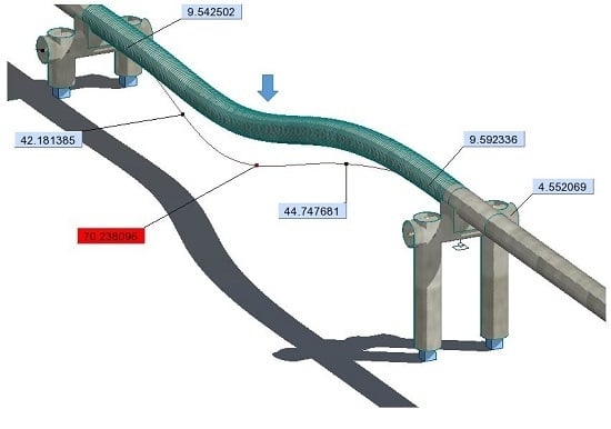
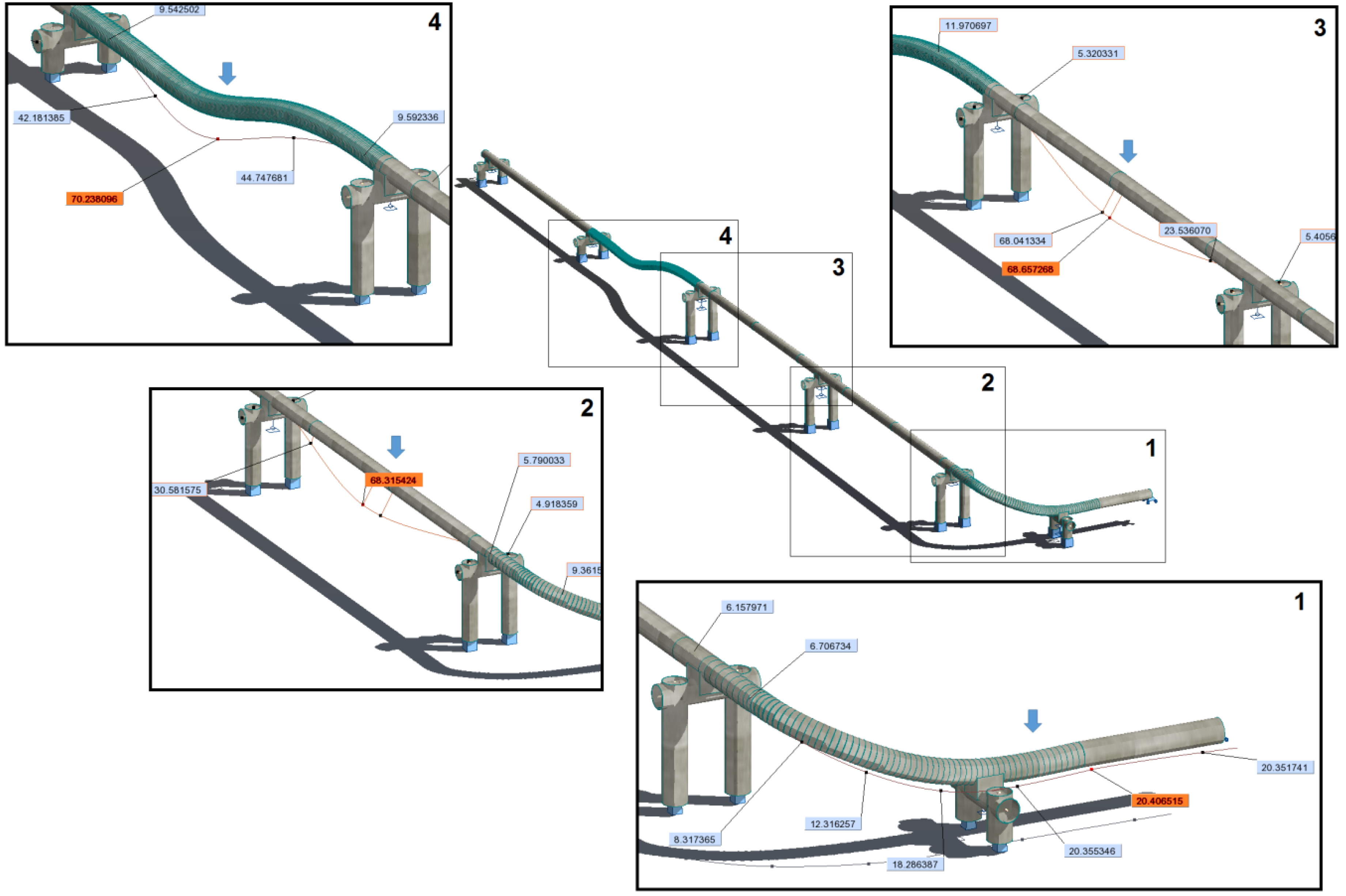
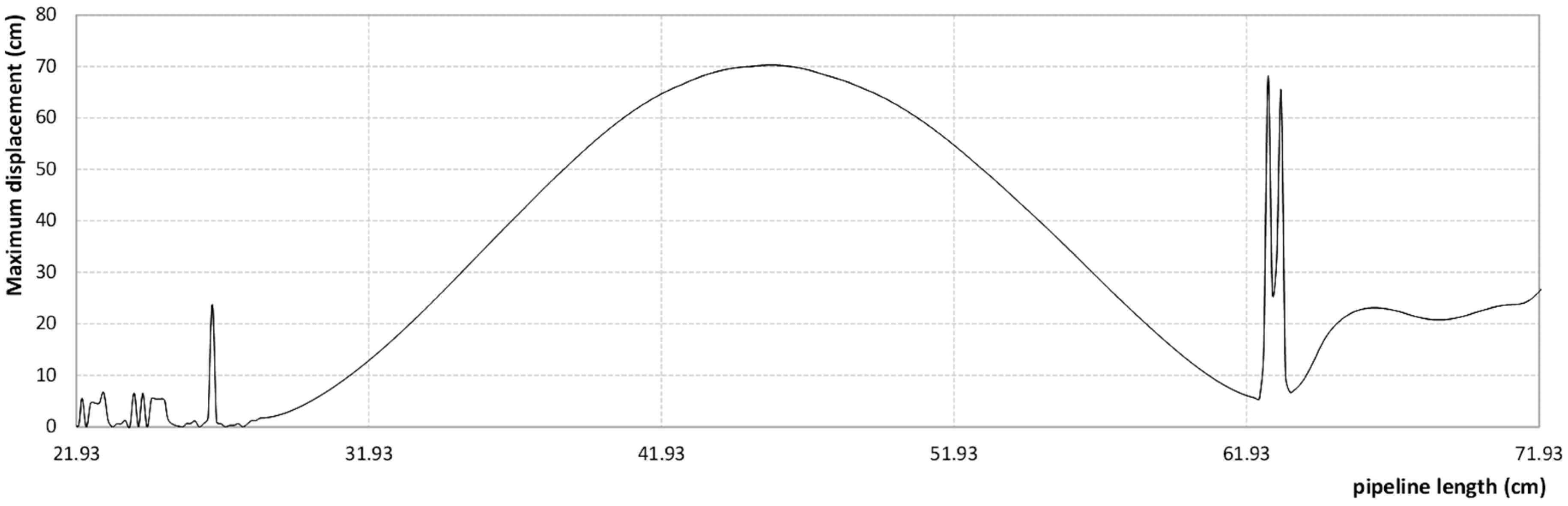
The vibration of the suspended pipeline under the action of a transient phenomenon described by a moving load gives results similar to the ones presented in situ. Moreover, the numerical results indicate that the maximum deflection at mid-span is 702.40 mm, which is 1.19 times the theoretical value (588.44 mm) and 0.94 less than the real value (750 mm). The difference between FEM and in situ measurements is not significant, confirming the dynamic behaviour of the structure under an impulsive load can be simulated using this model.
Figure 6 illustrates the maximum moving effect in each point of the structure under the moving load (
i.e., a water-hammer event).
From the deformed shape of the structure, some inconveniences can be observed, starting from the 1st to 20th m of length of the analysed pipe branch. As an overview, the deformed shape of this suspended pipeline has a point where the anchor supports, exceed their damping limit (
i.e., maximum expansion), permitting some elements to vibrate with a self-period. This influences the global behaviour of the entire structure leading to its fall, as it can be seen from
in situ pictures (see
Figure 1).
5. Conclusions
The purpose of this study is to ensure that in case of an extreme event, such as a water-hammer, the pipeline system will perform its intended function: position retention (the pipeline does not fall), leak tightness (the pipeline does not leak), and operability (the pipeline system delivers and regulates flow). However, when the pipeline is suspended, other constraints should be taken into account, due to the serious risk of damage by pipe buckling due to too high bending.
Based on existing pipeline damage, the structural flaws of the suspending oil pipeline were modelled using a finite element method. The suspending pipeline was calculated for two different combinations: ULS1-maximum overloading and ULS3-live. For the first, the structure fulfilled the safety conditions, unlike the ULS3 combination, where the standard design specifications failed in all aspects: (i) maximum pipeline bending stress; (ii) maximum deflection at mid-span; (iii) maximum acceptable stress; and (iv) damping limit. By using a moving point load in ULS3, the maximum mid-span achieved in the simulation results (i.e., 702.40 mm) are validated with the in situ measurements (i.e., ~750 mm).
The structural model can be used for simulating real extreme events where the maximum pressure is lower than the critical pressure (i.e., when extreme conditions are guaranteed). Thus, assuming here the water–hammer event as the maximum point load that moves along the pipeline, the results obtained give a good approximation of the real case and can be adopted by engineers and designers to meet pipeline protection standards.
Acknowledgments
This research was funded by the Portuguese Foundation for Science and Technology (FCT) through the Doctoral Grant—SFRH/BD/68293/2010 of the first author. Also, thanks to CEris (Civil Engineering Research and Innovation for Sustainability) of the Department of Civil Engineering, Architecture and Georesources, Instituto Superior Técnico (IST), Universidade de Lisboa.
Author Contributions
Mariana Simão simulated the accident according to the data, kindly lent by Igor Orynyak; Helena M. Ramos and Jesus Mora-Rodriguez analyzed the data; All authors contributed reagents/materials/analysis tools; Mariana Simão wrote the paper. Helena M. Ramos and Jesus Mora-Rodriguez reviewed the manuscript.
Conflicts of Interest
The authors declare no conflict of interest.
References
- Richie, A.M. Managing infrastructure problems that arise from earthquakes. Mater. Perform. 2003, 42, 48–51. [Google Scholar]
- Simão, M.; Mora, J.; Ramos, H.M. Fluid-structure interaction with different coupled models to analyse an accident occurring in a water supply system. J. Water Supply Res. Technol. Aqua 2015, 64, 302–315. [Google Scholar] [CrossRef]
- Simão, M.; Mora-Rodriguez, J.; Ramos, H.M. Mechanical interaction in pressurized pipe systems: Experiments and numerical models. Water 2015, 7, 6321–6350. [Google Scholar] [CrossRef]
- Ramos, H. Unsteady Flows: Water Systems Vulnerability; Lisbon Instituto Superior Técnico: Lisbon, Portugal, 2006. [Google Scholar]
- Ramos, H. Vulnerability Assessment in the Operational Management of Supply Systems; Lisbon Instituto Superior Técnico: Lisbon, Portugal, 2007. [Google Scholar]
- Ramos, H.; Almeida, A.B.; Borga, A.; Anderson, A. Simulation of severe hydraulic transient conditions in hydro and pump systems. Recur. Hídr. APRH 2005, 26, 7–16. [Google Scholar]
- Ramos, H.; Borga, A.; Bergant, A.; Covas, D. Analysis of surge effects in pipe systems by air release/venting. Recur. Hídr. APRH 2005, 26, 45–55. [Google Scholar]
- Rajani, B.; Zhan, C.; Kuraoka, S. Pipe-soil interaction analysis of jointed water mains. Can. Geotech. J. 1996, 33, 393–404. [Google Scholar] [CrossRef]
- Almeida, A.; Ramos, H. Water supply operation: Diagnosis and reliability analysis in a Lisbon pumping system. J. Water Supply Res. Technol. Aqua 2010, 59, 66–78. [Google Scholar] [CrossRef]
- Adachi, T.; Ellingwood, B. Serviceability of earthquake-damaged water systems: Effects of electrical power availability and power backup systems on system vulnerability. Reliab. Eng. Syst. Saf. 2008, 93, 78–88. [Google Scholar] [CrossRef]
- Lopes, M.; Leite, A. Economic Viability of Seismic Strengthening of Buildings; Ingenium: Greenbelt, MD, USA, 2005. [Google Scholar]
- Tucker, M. Bridge Crossings with Ductile Iron Pipe; Pipeline Division-American Society of Civil Engineers (ASCE): Denver, CO, USA, 1991. [Google Scholar]
- Gatulli, V.; Martinelli, L.; Perotti, F.; Vestroni, F. Dynamics of suspended cables under turbulence loading: Reduced models of wind field and mechanical system. J. Wind Eng. Wind Aerodyn. 2007, 95, 183–207. [Google Scholar] [CrossRef]
- Aronowitz, D.; Steward, N.; Bradley, R. The design of a suspended concrete transport pipeline system. J. South. Afr. Inst. Min. Metall. 2008, 108, 707–713. [Google Scholar]
- Zhang, X.; Sun, B. Aerodynamic stability of cable-stayed-suspension hybrid bridges. J. Zhejiang Univ. Sci. 2005, 6, 869. [Google Scholar] [CrossRef]
- Teng, Z.C.; Sun, J. A New Seismic Design Methods for Suspending Oil Pipeline. In Proceedings of the 2011 International Conference on Remote Sensing, Environment and Transportation Engineering (RSETE), Nanjing, China, 24–26 June 2011; pp. 2843–2847.
- Antaki, G.; Aiken, S. Seismic Design and Retrofit; American Lifelines alliance: Atlanta, GA, USA, 2002. [Google Scholar]
- Timoshenko, S.; Goodier, J. Theory of Elasticity, 3rd ed.; International Student, Ed.; McGraw-Hill: New York, NY, USA, 1982. [Google Scholar]
- Moussou, P.; Potapov, S.; Paulhiac, L.; Tijsseling, A. Industrial cases of FSI due to internal flows. In Proceedings of the 9th International Conference on Pressure Surges, Chester, UK, 24–26 March 2004; pp. 167–181.
- Bažant, Z.P.; Cedolin, L. Stability of Structures: Elastic, Inelastic, Fracture and Damage Theories, 1st ed.; World Scientific Publishing: Singapore, 2010. [Google Scholar]
- Yan, X.; Shide, H. Research on elastic dynamic stability of CFST arch model. J. Tongji. Univ. 2005, 33, 6–10. (In Chinese) [Google Scholar]
- Xiang, H.F.; Bao, W.G.; Chen, A.R.; Lin, Z.X.; Liu, J.X. Wind-Resistant Design Specification for Highway Bridges (JTG/TD60–01–2004); China Communications Press: Beijing, China, 2004. [Google Scholar]
- Orynyak, I.; Vasylyuk, V.; Radchenko, S.; Batur, A. The modelling of the dynamical behavior of the aerial pipeline bridge at the rupture of its underground part during the water pressure testing. Ukr. J. Oil Gas. Ind. 2006, 4, 27–32. (In Ukrainian) [Google Scholar]
- Advanced Structural Analysis Software. Available online: http://www.autodesk.com/products/robot-structural-analysis/overview (accessed on 13 June 2016).
- Zienkiewicz, O. The birth of the finite element method and of computational mechanics. Int. J. Numer. Method Eng. 2004, 60, 3–10. [Google Scholar] [CrossRef]
- Brenner, S.; Scott, R. The Mathematical Theory of Finite Element Methods, 2nd ed.; Springer-Verlag New York: New York, NY, USA, 2002. [Google Scholar]
- American Society of Mechanical Engineers (ASME B31.3). Engineering Standards Manual; ASME: New York, NY, USA, 2014. [Google Scholar]
- American Society of Mechanical Engineers (ASME B31.4). Liquid Petroleum Transportation Piping; ASME: New York, NY, USA, 2002. [Google Scholar]
- Telles, P.C.S. Industrial Pipes-Materials Projects and Assembly, 10th ed.; Editora LTC: Rio de Janeiro, Brazil, 2001. (In Portuguese) [Google Scholar]
© 2016 by the authors; licensee MDPI, Basel, Switzerland. This article is an open access article distributed under the terms and conditions of the Creative Commons Attribution (CC-BY) license (http://creativecommons.org/licenses/by/4.0/).


