Article

Floor Damage Evolution in Coal Mine Reservoirs

1
State Key Laboratory of Water Resource Protection and Utilization in Coal Mining, Beijing 102209, China
2
School of Energy and Mining Engineering, China University of Mining & Technology (Beijing), Beijing 100083, China
3
Bulianta Coal Mine, China Energy Shendong Coal Group Co., Ltd., Ordos 017209, China
4
Halagou Coal Mine, China Energy Shendong Coal Group Co., Ltd., Yulin 719315, China
*
Author to whom correspondence should be addressed.
Water 2026, 18(14), 1688; https://doi.org/10.3390/w18141688
Submission received: 23 May 2026 / Revised: 2 July 2026 / Accepted: 10 July 2026 / Published: 13 July 2026

Highlights

What are the main findings?
  • Storage pressure exceeding the 1.0 MPa threshold triggers deep floor failure via the “hydraulic wedging” mechanism.
  • Sandstone exhibits tensile cracking, while mudstone shows shear failure.
  • Burial depth strongly dictates failure depth, while mining height does not.
What are the implications of the main findings?
  • Mudstone floors provide superior water barrier performance for reservoirs.
  • Validates feasibility of building reservoirs in ultra-thick coal seams.
  • Operating water levels must be strictly kept below critical thresholds.

Abstract

Addressing the severe risks of floor instability and leakage in underground coal mine reservoirs in Western China under coupled mining and hydraulic pressures, this study developed a fully coupled stress-damage-seepage numerical model. Incorporating rock heterogeneity based on the geological conditions of the Shendong mining area, the model systematically simulates the evolution of floor damage under varying storage pressures, burial depths, mining heights, and lithologies. The simulation results demonstrate that storage pressure is the primary driver for deep damage propagation via a “hydraulic wedging” mechanism, governed by a critical activation threshold of 1.0 MPa. Specifically, before the water storage pressure reaches 1.0 MPa, the floor damage remains dormant and basically unchanged, stagnating at a shallow level. However, once the pressure exceeds this 1.0 MPa threshold, it overcomes the effective confining stress, abruptly shifting the failure mode from shallow discrete fracturing to deep penetrating failure, which is accompanied by an order-of-magnitude surge in permeability. Furthermore, a dimensionless sensitivity analysis reveals that burial depth and lithology strongly govern the failure path and depth. Notably, mudstone possesses a significantly lower intrinsic permeability, and even when subjected to damage, its water barrier performance remains superior to that of sandstone because its localized plastic shear characteristics highly restrict permeability mutations. In contrast, brittle sandstone is highly susceptible to tensile cracking and the formation of deep penetrating seepage channels. Additionally, mining height demonstrates weak sensitivity to the depth of floor damage due to an “equivalent unloading” mechanism, which validates the technical feasibility of constructing underground water reservoirs in ultra-thick coal seams. These findings provide a vital theoretical foundation for the scientific site selection of underground reservoirs and the precise determination of operational water level thresholds to ensure long-term stability.

1. Introduction

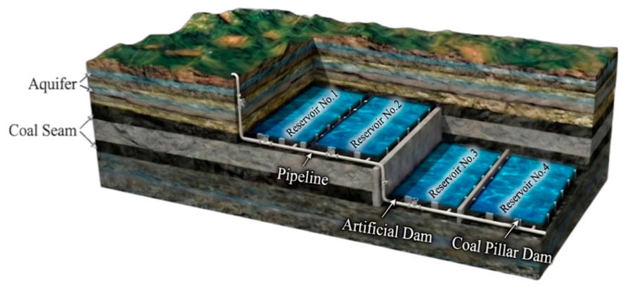
Coal resources are abundant in Western China, yet the region suffers from severe water scarcity and a fragile ecological environment. The annual evaporation capacity in this area is approximately six times that of precipitation, making natural rainfall insufficient to meet industrial and agricultural demands. Large-scale coal mining further exacerbates the contradiction between water supply and demand. The fracture fields induced by mining activities disrupt the original groundwater systems, causing massive amounts of mine water to be discharged to the surface and lost through evaporation, which results in both resource wastage and environmental pollution. To mitigate this conflict, Gu et al. proposed the integrated technology of “conduction, storage, and utilization” for underground coal mine reservoirs. This technology utilizes the natural space of the goaf to store and purify mine water, thereby achieving the recycling of water resources. Currently, more than 30 distributed underground reservoirs have been constructed in the Shendong mining area, significantly improving the utilization rate of mine water, The schematic diagram of the underground reservoir in the coal mine is shown in Figure 1 [1,2,3,4,5,6]. However, the long-term safety of underground reservoirs relies heavily on the stability of the reservoir structure. In particular, the floor of the goaf, affected by mining disturbances, faces the challenge of multi-field coupling involving “stress-seepage-damage” after water impoundment. Especially under the engineering conditions of reservoir groups, floor instability can lead to the water level in the lower reservoir exceeding limits, thereby affecting the stability of the dam body of the lower reservoir. Therefore, investigating the damage evolution laws and failure depth of the floor under the coupled action of mining and water pressure has significant theoretical value and engineering guidance significance for the scientific site selection of underground reservoirs, the precise definition of operating water level thresholds, and the long-term safety assurance of reservoir groups.
Regarding the damage and failure mechanisms of rock masses, scholars domestically and internationally have conducted extensive and fruitful research. In terms of theoretical models, based on continuous damage mechanics and fracture mechanics, scholars have established various rock damage constitutive models. Liu et al. [7] defined damage variables from the perspective of energy dissipation, revealing the energy evolution mechanism during rock failure. Yao et al. [8] established a statistical damage constitutive model under compound disturbances, which well described rock deterioration behavior under complex stress paths. Ru et al. [9] introduced fractional derivative theory to construct a non-linear constitutive model capable of describing the entire process of rock creep damage, providing a new tool for rheological analysis of rock masses under long-term water pressure. Targeting deep high-stress environments, Lu et al. [10] proposed a thermal-mechanical-damage statistical constitutive model considering temperature effects, correcting the prediction deviation of the traditional Hoek-Brown criterion under high confining pressures. Hu et al. [11] further improved the traditional Drucker-Prager criterion by proposing a damage-based cohesion weakening-friction strengthening (DP-CWFS) constitutive model, which significantly improved the accuracy of stability analysis for deep rock masses. In terms of micro-meso damage characterization, with advancements in CT scanning and nuclear magnetic resonance (NMR) technologies, the evolution process of internal pore structures in rocks has become visible and measurable. Bi et al. [12] conducted triaxial compression tests on sandstone samples using real-time T2-weighted NMR spectra and imaging, while Chen [13] carried out damage evolution tests on limestone samples under hydro-mechanical coupling, revealing the driving mechanism of high seepage pressure on microscopic pore expansion.
In the research of seepage-stress coupling characteristics, existing results mostly focus on the field of “floor water inrush,” specifically the process of confined water breaking through from the bottom up. Yu [14] conducted systematic research on the failure depth of the damaged floor in mining stopes relatively early, defining the spatial morphology of the floor failure zone through theoretical analysis and field measurements. Liu et al. [15], based on thin plate theory, established a mechanical discrimination model for the risk of floor water inrush. regarding mechanism research, Chen et al. [16] confirmed through triaxial seepage tests that unloading of confining pressure and increasing osmotic pressure lead to an exponential increase in rock permeability. Zhu et al. [17] established a thermal-hydro-mechanical (THM) coupling model considering damage evolution, deeply analyzed the mechanical effect of pore water pressure on rock damage, and elucidated the evolution law of tensile damage extension to depths induced by high seepage pressure. Yang et al. [18] and Shao et al. [19] simulated the formation of water inrush channels based on COMSOL and micromechanical models, respectively. Shao et al. [20] constructed a stress-seepage-damage coupling model, reproducing the crack propagation path of hidden faults under mining unloading and water pressure driving forces. Xu et al. [21] studied the damage deterioration mechanism of water-immersed coal pillars and floors under long-term physicochemical actions in abandoned mine goafs, proposing a long-term stability evaluation method based on the “damage coefficient.” Li et al. [22] systematically studied the failure mechanism of deep mining floors, pointing out that under the superposition of mining stress and high confined water, the floor failure depth increases significantly and exhibits complex non-linear evolution characteristics.
Despite extensive research on the characteristics of mining-induced floor failure, the damage mechanism under the condition of long-term water storage in underground coal mine reservoirs remains unclear. Specifically, there is a lack of quantitative models describing the non-linear response relationship between storage pressure and failure depth. In view of this, taking the typical geological conditions of the Shendong mining area as the background, this paper constructs a fully coupled stress-damage-seepage numerical model considering rock heterogeneity based on the theory of fluid-solid coupling in porous media and continuous damage mechanics. The model systematically simulates the mechanical response throughout the full life cycle of “initial rock stress balance-coal seam excavation-goaf water impoundment.” On this basis, the study focuses on exploring the floor damage evolution laws under the coupled effects of multiple factors, including storage pressure, burial depth, mining height, and lithology. Furthermore, dimensionless sensitivity coefficients are introduced to quantify the control weights of various key factors. The aim is to reveal the deep-seated mechanisms of floor instability in underground reservoirs, thereby providing scientific basis and technical support for site selection optimization, storage capacity design, and the determination of operating water level thresholds for underground coal mine reservoirs in Western China.

2. Stress-Damage-Seepage Coupled Theoretical Model

The floor rock mass of an underground coal mine reservoir is a heterogeneous medium containing defects such as pores and fractures. Under the combined action of mining-induced stress and reservoir water pressure, the internal rock mass undergoes not only stress redistribution and skeletal deformation but also the initiation and propagation of micro-cracks, which subsequently leads to abrupt changes in permeability [23]. To accurately describe this complex physical process, this paper establishes a fully coupled mathematical model incorporating stress, seepage, and damage fields, based on the theory of fluid-solid coupling in porous media and continuous damage mechanics.

2.1. Multi-Physics Field Coupling Mechanism Framework

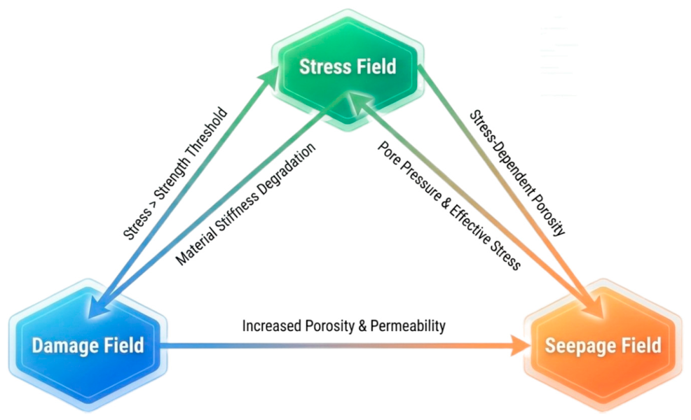
This chapter constructs a fully coupled stress-damage-seepage theoretical model (as shown in Figure 2). This coupling system, based on the Biot porous media theory, realizes the bidirectional interaction between the stress field and the seepage field. On one hand, pore water pressure affects the deformation of the rock skeleton by altering the effective stress, thereby reducing the shear strength of the rock mass. On the other hand, the volumetric deformation of the rock induces dynamic adjustments in porosity, which inversely alters the permeability. On this basis, a damage variable is introduced as the core nexus: mining-induced stress leads to rock damage and stiffness degradation, while the accumulation of damage further triggers the “mutation effect” of permeability—specifically, fracture coalescence causes an exponential increase in permeability. This multi-field mutual feedback mechanism can realistically reveal the evolutionary mechanism of the floor aquiclude, transitioning from microscopic fracturing to the formation of macroscopic water-conducting channels.

2.2. Solid Mechanical Equilibrium and Damage Evolution Equations

2.2.1. Solid Mechanical Equilibrium Equations

Before mining, the rock is in a state of mechanical equilibrium. Based on Biot’s theory of effective stress, the stress state can be described by the equilibrium equations of solid mechanics:
E 2 ( 1 + ν ) μ i , i j + E 2 ( 1 + ν ) ( 1 2 ν ) μ j , j i + α p + F i = 0
In the formula: E is the Young’s modulus of the rock, ν is the Poisson’s ratio of the rock, F i and μ i , i j are the components of body force and displacement in the i direction, respectively, with the compressive stress direction being positive, α is the Biot coefficient of the medium, which is not greater than 1, and is taken as 0.5 here, and p is the pore water pressure. Although the Biot coefficient varies with lithology (typically 0.4–0.7 for deep coal-measure strata), this study focuses on macroscopic damage evolution and permeability surges driven by high water pressure, making pre-failure poroelastic differences a secondary factor. To simplify parameter dimensions in the large-scale coupled model and isolate primary controlling factors, α = 0.5 is adopted as a representative equivalent constant for all lithologies. This aligns with common engineering simplifications in macroscopic mining geomechanics simulations [17].

2.2.2. Damage Discrimination Equation

To accurately describe the deterioration behavior of rocks during mining, tensile and shear damage criteria are constructed based on the maximum tensile stress criterion and the Mohr-Coulomb criterion, respectively. Assuming that the degree of damage evolution is closely related to the principal strain state of the rock mass element, the governing equations are as follows:
F 1 = σ 3 f t 0
F 2 = σ 1 σ 3 1 + sin φ 1 sin φ f c 0
max 0 F 1 < 0 , F 2 < 0 1 ε t 0 ε 3 n F 1 = 0 ,       d F 1 > 0 1 ε c 0 ε 1 n F 2 = 0 , d F 2 > 0
In the formula: F 1 and F 2 represent functions of the tensile and shear states, respectively; f t 0 and f c 0 represent the uniaxial tensile and compressive strengths of the medium, respectively; φ represents the internal friction angle of the medium; σ 1 and σ 3 represent the maximum and minimum principal stresses of the element, respectively; ε 1 and ε 3 represent the maximum and minimum principal strains of the element, respectively; ε t 0 and ε c 0 represent the maximum tensile principal strain and maximum compressive principal strain corresponding to tensile and shear damage, respectively; n is a coefficient for element damage evolution, here taken as n = 2; d F 1 > 0 and d F 2 > 0 represent the continued loading states after the two types of damage, which can cause an increase in the damage variable. When d F 1 < 0 or d F 2 < 0 is less than or equal to 0, it represents the unloading state, no new damage is generated, and the damage variable retains the value of the previous loading step.
Under complex stress paths where an element may experience both tensile and shear failure modes, the total damage variable is governed by a maximum envelope rule, taking the maximum value between the tensile damage and shear damage to satisfy the thermodynamic irreversibility of material degradation.
According to the elastic damage theory, the elastic modulus of the element is given by the following relationship:
E = ( 1 D ) E 0
In the formula, E0 and E are the elastic moduli before and after the damage, respectively. It is assumed here that the damage and its evolution are isotropic, so E, E0 and D are all scalars.
It is worth noting that during the actual loading and failure process of rocks, macroscopic instability and failure typically occur well before the damage variable D reaches 1. Relevant theoretical and experimental studies have demonstrated that rock materials such as sandstone possess a critical damage threshold (D > 0.4). Once the damage variable exceeds this threshold, internal micro-cracks coalesce rapidly, driving the rock into an accelerated macroeconomic failure stage [24]. Grounded on this mechanism, to accurately and conservatively characterize the macroscopic instability and failure state of the floor rock mass, a critical damage threshold of D ≥ 0.4 is defined as the criterion for macroscopic rock failure (i.e., the rock completely loses its bearing capacity and macroscopic fractures coalesce) in this study. All subsequent quantitative statistics regarding the maximum failure depth of the floor are strictly based on this D ≥ 0.4 threshold.

2.3. The Effect of Damage on the Seepage Field

The porosity of a rock stratum is related to its stress state, and this relationship can be expressed as follows:
ϕ = ( ϕ 0 ϕ r ) exp ( α ϕ σ v ¯ ) + ϕ r
In the formula: ϕ 0 is the porosity under zero stress; α ϕ is the stress sensitivity coefficient of porosity, taken as 5.0 × 10⁻⁸ Pa−1; ϕ r is the limiting value of porosity under high compressive stress; σ v ¯ is the average effective stress, calculated according to the following formula:
σ v ¯ = ( σ 1 + σ 2 + σ 3 ) / 3 α p
In the formula: α is the Biot coefficient, and σ 1 , σ 2 , and σ 3 are the three principal stresses. Furthermore, the relationship between permeability and porosity can be considered to satisfy the following power function relationship:
k = k 0 ( ϕ / ϕ 0 ) 3
In the formula: k0 is the permeability (m2) under zero stress; k is the permeability (m2) after being subjected to stress. This power-aw relationship is derived from the classic Kozeny-Carman equation and hasbeen widely validated in coupled stress-seepage studies [17]. The baseline parameters (k0 and ϕ 0 ) for different strata were calibrated based on the in-situ hydrogeological testreports of the target mine.
A generative AI tool, Gemini 1.5 Pro (Google), was utilized to assist in the visual refinement and aesthetic rendering of Figure 1. The authors thoroughly reviewed and edited the output to ensure scientific accuracy.

3. Establishment of the Numerical Simulation Model for Underground Coal Mine Reservoirs

3.1. Engineering Geological Overview

This study selects a representative mine in the Shendong mining area as the engineering background. Located in the northern Ordos Basin, the mining area features gently dipping strata and a simple geological structure. The primary coal-bearing strata belong to the Middle-Lower Jurassic Yan’an Formation, with roof and floor lithologies predominantly characterized by interbedded sandstone and mudstone. Based on geological borehole data, a typical profile was selected for generalized modeling. The average thickness of the target coal seam is 6 m. The floor is mainly composed of sandstone and mudstone; the differences in permeability characteristics and damage evolution laws between these two lithologies are critical factors determining the stability of the floor aquiclude.

3.2. Numerical Model Construction and Simulation Scheme

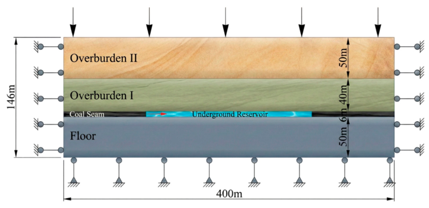
Based on the aforementioned engineering geological conditions, a coupled model was constructed using the “Solid Mechanics” and “Darcy’s Law” modules in COMSOL Multiphysics 6.3. The model geometry dimensions were set to 400 m (length) × 300 m (width) × 146 m (height), with a coal seam thickness of 6 m. Considering the geological structure of interbedded sandstone and mudstone in the overlying strata, the overburden was equivalently generalized into Overburden I and Overburden II, with thicknesses of 40 m and 50 m, respectively. The floor strata thickness is 50 m. A boundary load of 6 MPa was applied to the top of the model to simulate the weight of theoverlying strata, establishing the initial vertical stress. Roller supports were applied to thelateral boundaries of the model (restricting horizontal displacement to zero), while thebottom boundary was set as a fixed constraint, under this boundary configuration, thehorizontal in-situ stresses are naturally incorporated and self-generated during the initial in-situ stress equilibrium phase via the Poisson’s effect of the rock mass. Specifically, themagnitude of the generated horizontal stress is theoretically determined by the verticalstress and the Poisson’s ratio of each specific stratum. This gravity-dominated stress fieldinitialization is consistent with the geological reality of the Shendong mining area, whichfeatures simple geological structures and no dominant tectonic stress. The domain was discretized using a free triangular mesh. Regarding model solving and convergence control, considering the strong nonlinearity of the multi-physics coupled excavation process, a Fully Coupled Solver was utilized. To ensure computational accuracy, this model avoided artificially enlarging the error tolerance to force convergence; instead, the relative tolerance for nonlinear iterations was strictly limited to 0.001. Furthermore, this was combined with a refined step-size control of 1 m/step during the excavation phase and an automatic damping mechanism within the solver to smooth stress redistribution, thereby achieving stable model convergence without sacrificing accuracy. To eliminate boundary effects, 100 m wide coal pillars were reserved on both sides along the strike direction. The working face advances from left to right. The geometric model is illustrated in Figure 3.
To systematically reveal the floor damage evolution mechanism under coupled mining and water pressure, the numerical simulation process strictly followed the temporal sequence of “initial in-situ stress equilibrium–continuous coal seam excavation–goaf water impoundment.” First, the initial in-situ stress equilibrium was calculated. Subsequently, using the activation feature in the Solid Mechanics module, the excavation step was set to 1 m, with damage variables and elastic modulus updated in real-time after each excavation step, until the face advanced to 200 m and a stable stress and displacement field in the goaf was formed. On this basis, the simulation transitioned to the underground reservoir water impoundment stage, where different water pressures were applied to the reservoir floor. Comparative tests were conducted by setting different working conditions for floor lithology, burial depth, and mining height. The aim was to quantitatively reveal the influence laws of water pressure magnitude and geological occurrence environment on floor failure depth and the connection of seepage channels.
To verify the numerical stability of the model and eliminate the interference of mesh size, a mesh independence analysis was conducted prior to the formal simulations. Using the maximum floor failure depth at an advancing distance of 200 m under non-water-pressure conditions as the evaluation metric, four mesh schemes with different densities (corresponding to total element counts of 1164, 1382, 1467, and 2982) were tested. The results indicate that the floor failure depths are highly consistent across these four meshes (all stabilizing at approximately 28.11 m), showing no mesh dependency. This fully demonstrates the high robustness of this model in terms of parameter settings and solution strategies. Considering both the efficiency and accuracy of the nonlinear calculation, the “Fine” mesh configuration with 1467 elements was ultimately selected for all multi-physics coupled simulations in this study.

3.3. Rock Mechanical Parameters and Heterogeneity Characterization

The mechanical properties of rock masses within a geological environment are spatially unevenly distributed. To reflect the heterogeneity of the bedrock, the WeiBull statistical distribution function is introduced to describe the various physical and mechanical parameters of the rock mass, namely:
φ ( α ) = m α 0 ( α α 0 ) m 1 e ( α α 0 ) m
In the formula, α represents the rock mass material parameters (elastic modulus, etc.); α 0 represents the mean value of the material parameters; m represents the uniformity coefficient; and φ ( α ) represents the statistical distribution density of the rock mass mechanical property α . Based on the macroscopic mechanical characteristics of typical coal-measure sedimentary rocks, the homogeneity coefficient m was set to 3.0 in this study. This value effectively characterizes the natural heterogeneity and primary defect distribution of the strata [25].
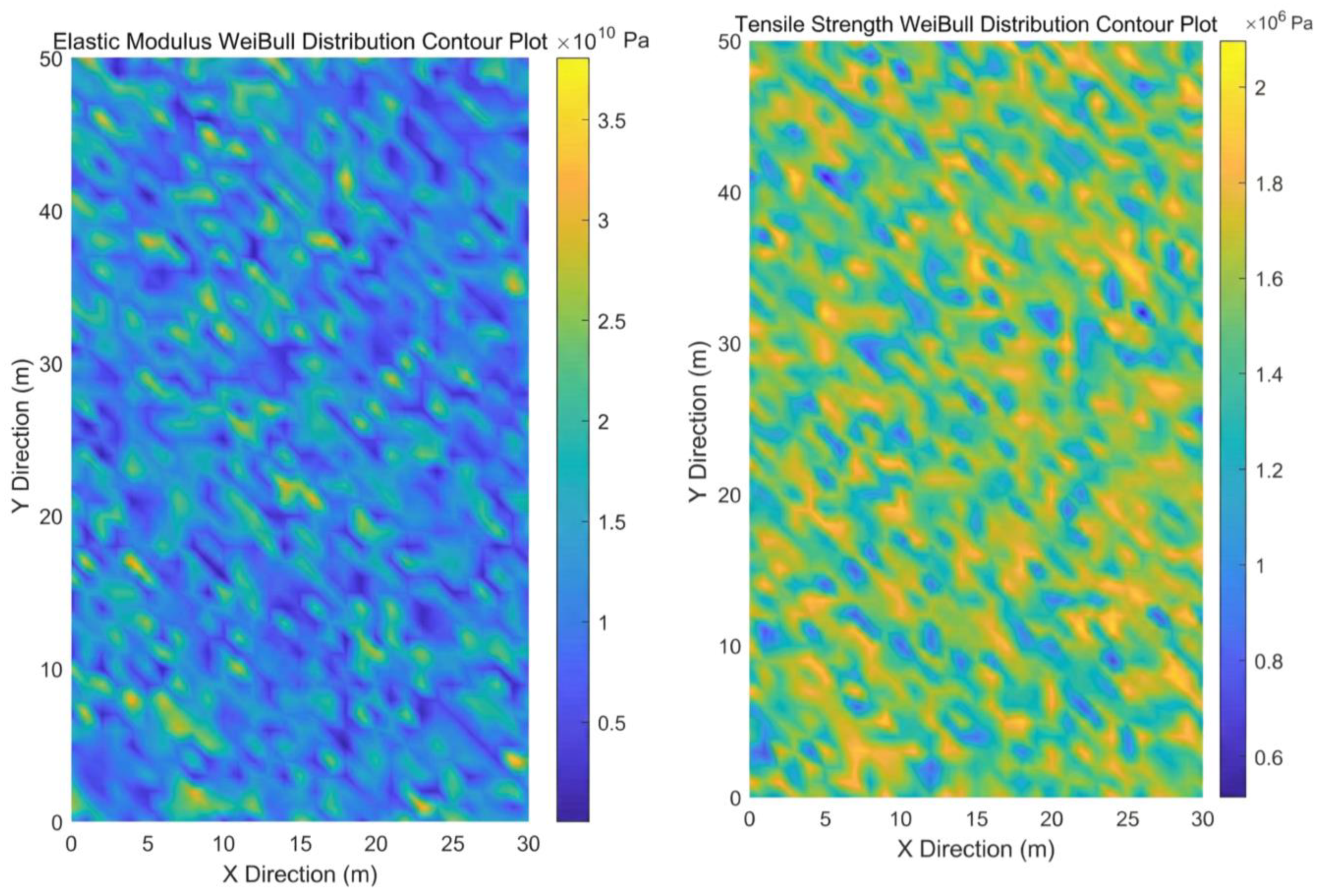
Based on the known average physical and mechanical parameters of rock micro-elements, a MATLAB program (MATLAB R2024a, MathWorks) was used to generate a series of data conforming to the Weibull distribution, which were then assigned to the corresponding rock micro-elements. The baseline values of the physical, mechanical, and seepage parameters of each rock layer in the model were determined comprehensively based on the mine’s rock mechanics test report and geological exploration data. The specific mechanical and seepage parameters of the model are shown in Table 1, and the heterogeneous distributions of the elastic modulus and tensile strength for the floor plate, processed via the Weibull distribution, are shown in Figure 4.

4. Results and Analysis of Numerical Simulation

4.1. Evolution Characteristics of Stress and Displacement Fields in the Mining Floor

4.1.1. Evolution Characteristics of the Stress Field in the Mining Floor

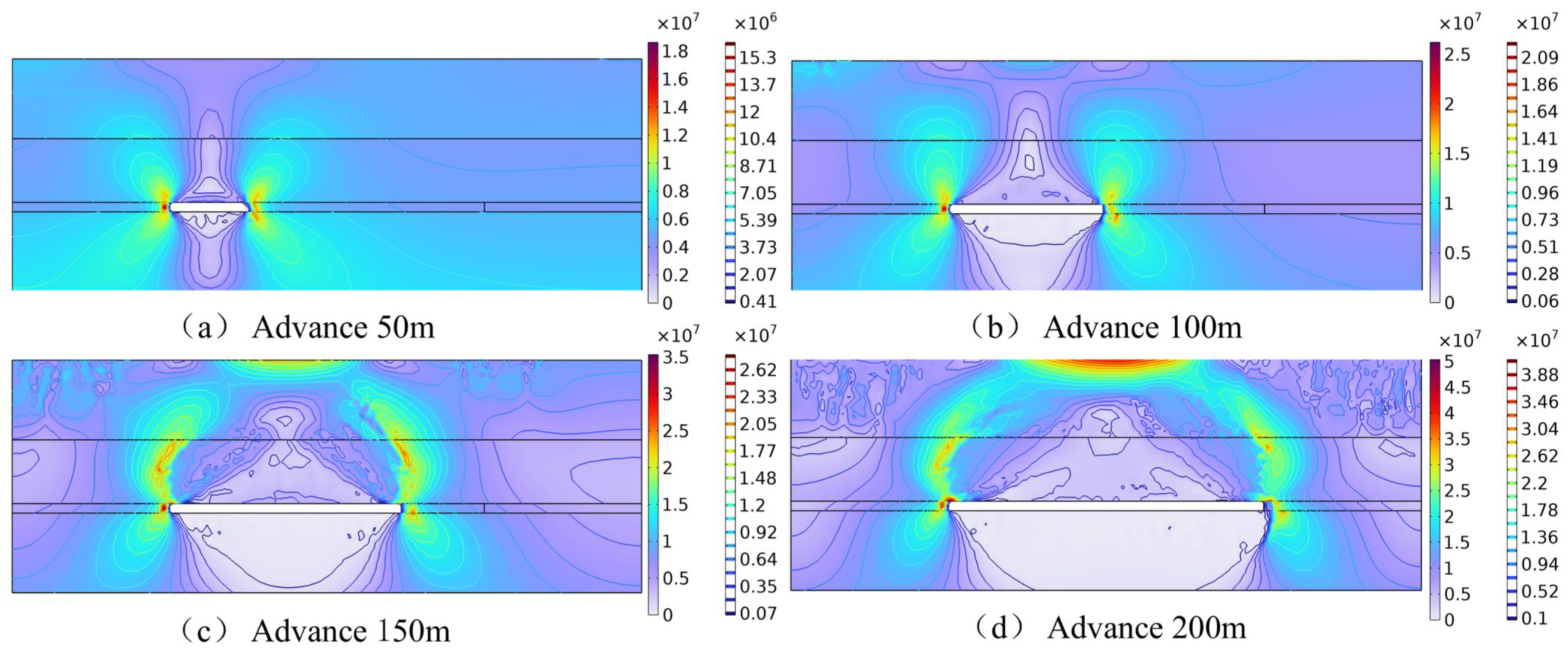
Coal seam mining disrupts the original in-situ stress equilibrium, causing the load from the overlying strata to transfer toward the boundaries of the goaf and inducing stress redistribution in the surrounding rock [26]. Figure 5 presents the contour maps of vertical stress distribution at different advancing distances of the working face. As illustrated in the figure, with the advancement of the working face, a distinct “stress arch” structure forms above the goaf, and the span of the arch expands continuously as the mining area enlarges. The load from the overlying strata is primarily borne by the coal pillars ahead of the working face coal wall and behind the open-off cut, creating significant abutment pressure concentration zones. As the working face advances, the vertical stress on both sides increases gradually. When the advancing distance reaches 200 m, the peak stress on both sides is approximately 40–50 MPa.
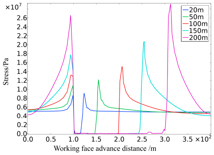
In sharp contrast to the abutment pressure zones, the floor in the central area of the goaf exhibits an extensive low-stress zone. To quantitatively reveal the evolutionary characteristics of floor stress, a monitoring line was established at the floor surface (0 m depth) to investigate stress variations along the strike direction at different advancing distances of the working face (Figure 6). The curves indicate that the vertical stress on the floor surface in the middle of the goaf drops drastically to 0–1 MPa, far below the initial in-situ stress level, demonstrating a significant “unloading effect.” This removal of vertical constraint directly induces upward rebound deformation and volumetric dilation of the floor strata. In this state, internal micro-cracks within the rock mass reopen due to the loss of normal clamping force, leading to the simultaneous degradation of floor strength and seepage resistance. Consequently, this area becomes a weak zone susceptible to damage and fracture coalescence after the underground reservoir is impounded.

4.1.2. Evolution Characteristics of the Displacement Field in the Mining Floor

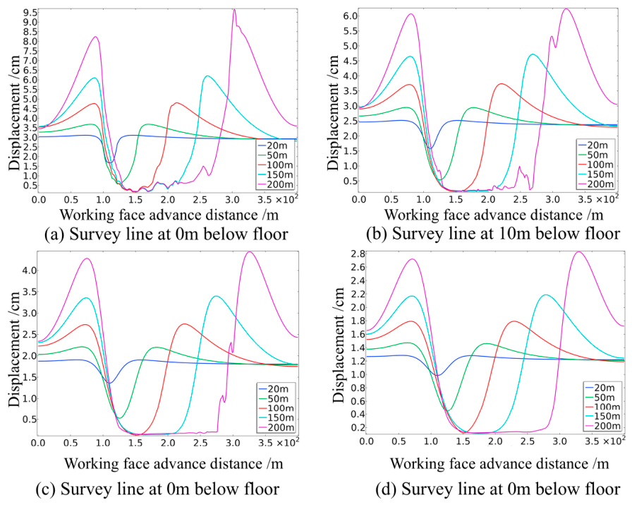
To comprehensively reveal the evolutionary characteristics of the model’s vertical displacement, monitoring lines were positioned at vertical depths of 0 m, 10 m, 20 m, and 30 m below the floor. The obtained data are presented in Figure 7. Observations indicate that the floor displacement field exhibits a typical “saddle-shaped” spatial distribution characterized by “larger values at the ends and smaller values in the middle.”
Taking the scenario where the working face advances to 200 m as an example, under the influence of high abutment pressure on both sides of the goaf, the floor surface (0 m depth) exhibits significant displacement peaks beneath the coal wall and the open-off cut, with a maximum vertical displacement reaching 9.5 cm. In contrast, in the central area of the goaf, due to the compaction from roof collapse, the floor rebound is constrained; the displacement rapidly declines and stabilizes at approximately 0.5 cm. The peak-to-valley difference reaches 9 cm, demonstrating strong spatial heterogeneity.
Furthermore, floor displacement exhibits a significant non-linear attenuation pattern with increasing depth. As the monitoring depth increases from 0 m to 30 m, the peaks of the displacement curves are notably “flattened”; the peak displacement decreases from 9.5 cm to 2.8 cm, representing an attenuation rate of up to 70.5%. This indicates that the mining-induced disturbance to the floor is primarily concentrated within the shallow strata, while the influence of mining unloading and abutment pressure on the deep rock mass gradually diminishes.

4.2. Evolution Mechanism of Floor Damage and Seepage Under Coupled Mining and Water Pressure

4.2.1. Influence of Mining on the Characteristic Depth of Floor Damage

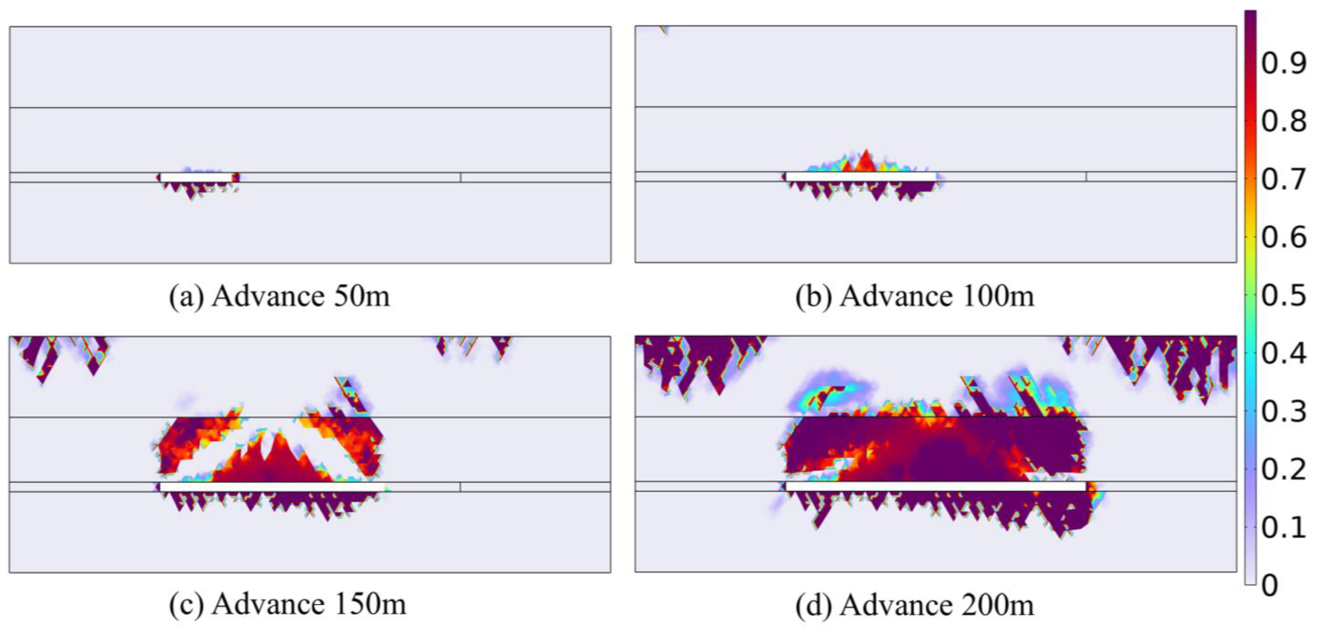
Figure 8 illustrates the spatiotemporal evolution characteristics of the floor damage field during the advancement of the working face. The numerical simulation results indicate that:
During the initial mining stage (advancing 50 m to 100 m), due to the limited suspended area of the goaf, the floor rock mass is primarily subjected to local unloading and abutment pressure. Consequently, the damage zone mainly develops within the immediate floor at the center of the goaf, exhibiting a shallow, band-like distribution. The maximum failure depth increases slowly from 10.14 m to 12.18 m, with no significant extension into the deeper strata.
However, when the advancing distance increases to 150 m, influenced by the strong unloading effect caused by the increased span of the goaf, the floor failure mode transitions from the initial “shallow discrete type” to a “deep penetrating type.” The maximum failure depth reaches 22.4 m.
Ultimately, when the working face advances to 200 m, the maximum damage depth reaches a peak of 28.11 m. This indicates that mining action alone generates a fracture development zone of a certain depth within the floor. These mining-induced fractures will serve as preferential channels for the “hydraulic wedging” of high-pressure water during the subsequent water impoundment phase of the underground reservoir.
To validate the reliability of the established numerical model, the baseline simulation result was compared with classical empirical formulas for floor failure depth widely applied in coal mining engineering. According to the established statistical empirical formulas and slip-line field theories endorsed by Chinese coal mine safety regulations, the theoretical mining-induced floor failure depth for a coal seam with a thickness of 6 m and similar geological conditions generally ranges from 24 m to 30 m, which also aligns closely with typical field measurement data from the Shendong mining area. The simulated maximum failure depth of 28.11 m falls precisely within this theoretical and practical prediction range. This high degree of consistency confirms that the model parameter settings, including the application of the Weibull distribution to characterize rock heterogeneity, are highly rational and effectively capture the macroscopic mechanical behavior of the floor rock mass. Consequently, this comprehensive validation provides a credible and robust foundation for the subsequent multi-physics coupled analyses involving high water storage pressures [14,27].

4.2.2. Influence of Water Pressure on Floor Damage Depth

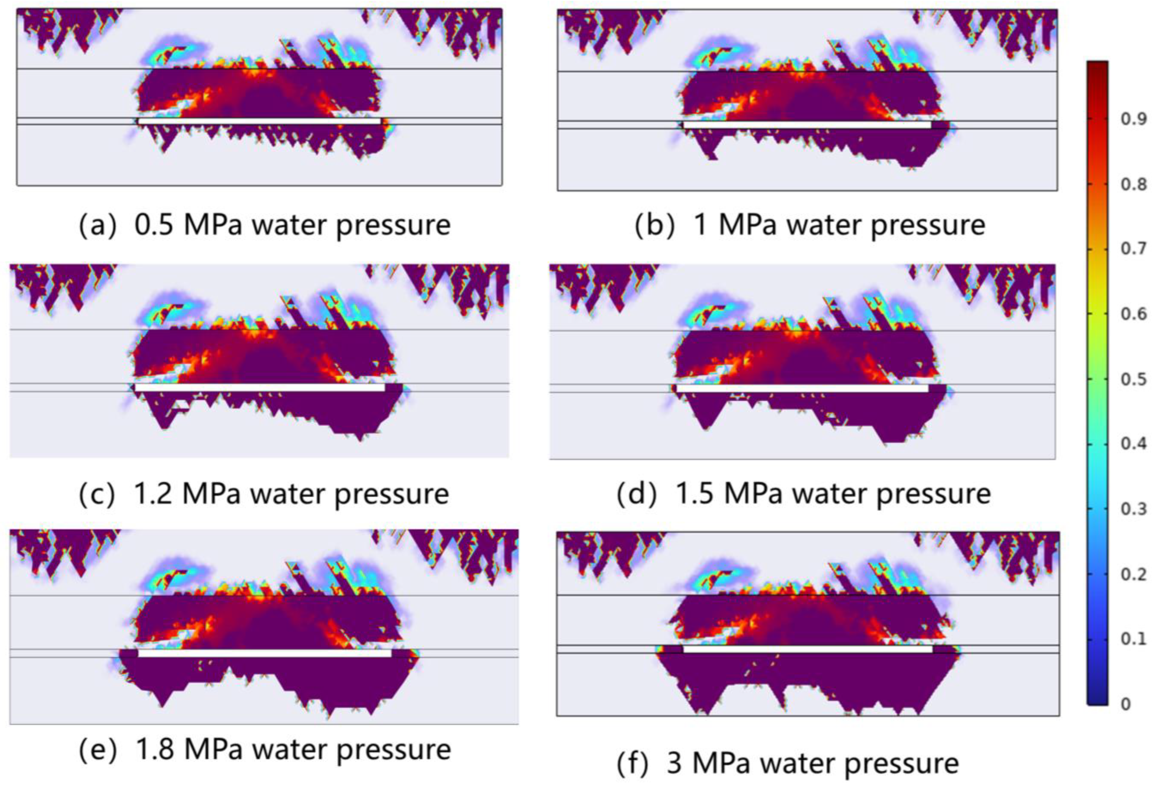
After the completion of coal seam extraction, the goaf transitions into the operational phase of underground reservoir water impoundment. During this phase, the floor rock mass is subjected to the hydrostatic pressure of the accumulated water, superimposed on the residual abutment pressure from the overlying strata. Figure 9 illustrates the evolutionary characteristics of the floor damage field under varying water storage pressures.
Comparative analysis of the supplemented data in Figure 9 indicates that the extent of floor damage exhibits a distinctly non-linear expansion trend. In the low water pressure stage (Figure 9a,b), the effective confining pressure of the floor rock mass is sufficient to resist the hydraulic driving force. Consequently, the morphology of floor damage remains consistent with that of the water-free mining stage, with the maximum failure depth stagnating at a shallow level. This demonstrates that damage expansion is essentially dormant below 1.0 MPa. However, 1.0 MPa serves as the critical activation threshold. Once the pressure exceeds this point (Figure 9c,d), the damage breaks its stagnation. The fracture tips begin to propagate downwards progressively, transforming the initial “shallow discrete type” into a distinct “wedge” shape. When the pressure further reaches 1.8 MPa (Figure 9e), the damage zone undergoes a qualitative transition, with the failure depth surging abruptly to form a massive deep damage zone. Ultimately, when the water pressure rises to 3.0 MPa (Figure 9f), the maximum damage depth completely penetrates the floor, reaching the model boundary of 50 m.
This continuous geometric evolution physically visualizes the “hydraulic wedging” mechanism under seepage-stress coupling. According to the effective stress principle, as the water level rises beyond the 1.0 MPa threshold, the pore water pressure directly offsets the effective confining pressure on the rock skeleton, causing deep micro-cracks that were originally compressed to reopen. Simultaneously, at the tips of initial fractures induced by mining, high-pressure water generates immense tensile stress concentration, driving the fractures to propagate continuously deeper like a wedge. This secondary failure induced by hydraulic wedging is highly likely to connect deep strata, significantly increasing the risk of floor water inrush or reservoir leakage.

4.2.3. Laws of Damage-Induced Permeability Mutation

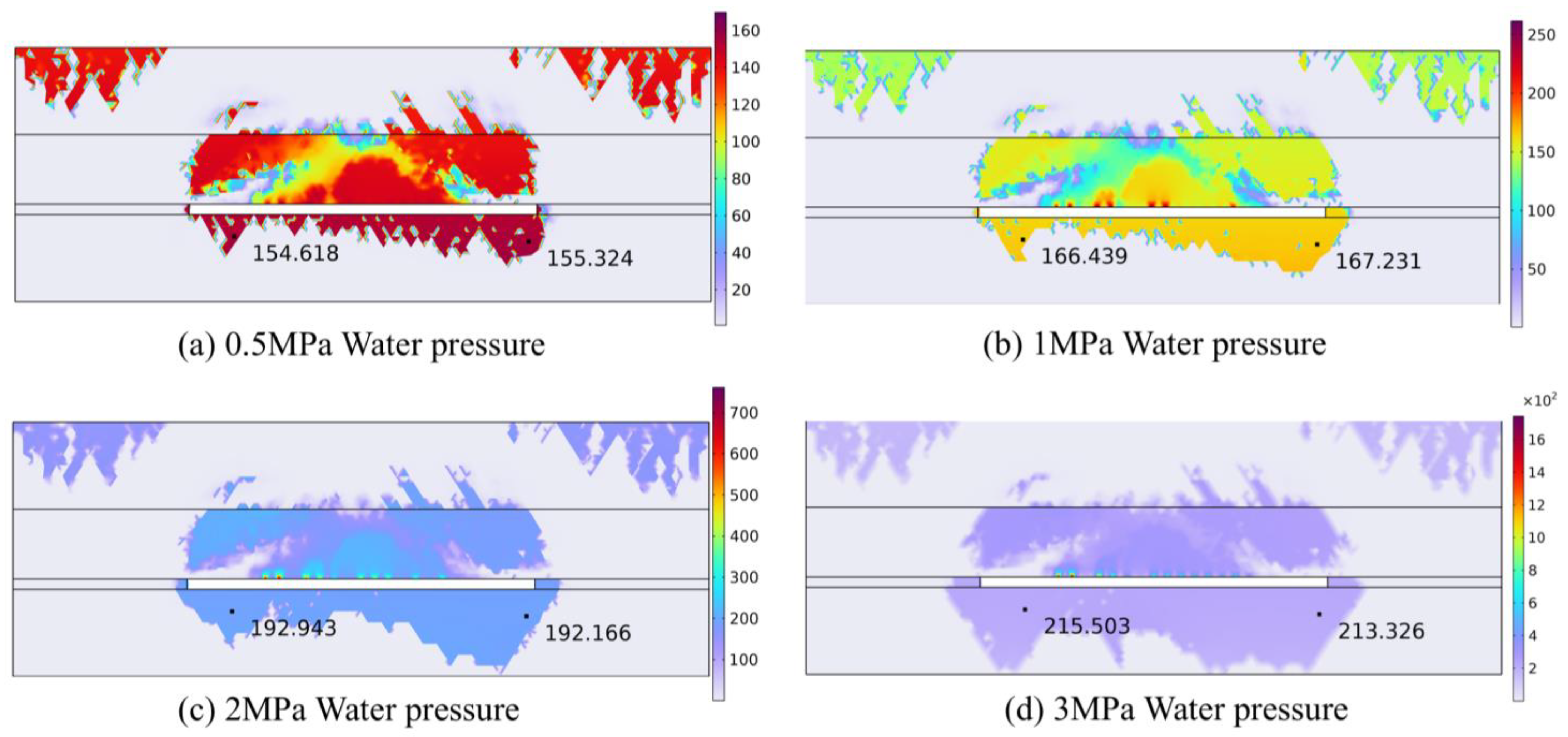
The direct consequence of the damage field evolution is a drastic alteration in the seepage properties of the floor rock mass. The abrupt change (mutation) in permeability is the critical factor inducing the transition of the underground reservoir floor from an “aquiclude” (water barrier) to a “permeable zone.” Figure 10 illustrates the spatial distribution characteristics of the permeability increase factor of the floor under different storage pressures.
The simulation results indicate a significant positive correlation between the permeability evolution of the floor rock mass and the degree of damage. In regions with no or minor damage, the rock mass maintains a dense structure, and permeability increases only marginally. However, in zones of concentrated damage, the coalescence of the internal fracture network results in an order-of-magnitude surge in permeability.
Specifically, when the water pressure is 0.5 MPa, the permeability increase factor of the floor is approximately 155 times; at this stage, high-permeability zones are scattered, and the overall sealing capacity of the floor remains relatively intact. As the water pressure rises to 1.0 MPa and 2.0 MPa, the permeability increase factors at the same location increase to 167 times and 192 times, respectively, indicating the gradual expansion of fracture channels. When the water pressure further increases to 3.0 MPa, the permeability increase factor reaches 215 times, representing an increase of approximately 38.7% compared to that at 0.5 MPa. At this point, a clearly defined “inverted trapezoidal” high-permeability channel forms beneath the goaf floor. This channel directly connects the underground reservoir with the deep strata, enabling the reservoir water to seep downward rapidly along this preferential path. This validates that high-pressure hydraulic fracturing not only destroys the rock skeleton but also, by inducing a permeability mutation, fundamentally leads to the failure of the floor aquiclude.

4.3. Analysis of Differences in Floor Stability Under Various Geological Occurrence Environments

4.3.1. Influence of Floor Lithology on Floor Damage Depth

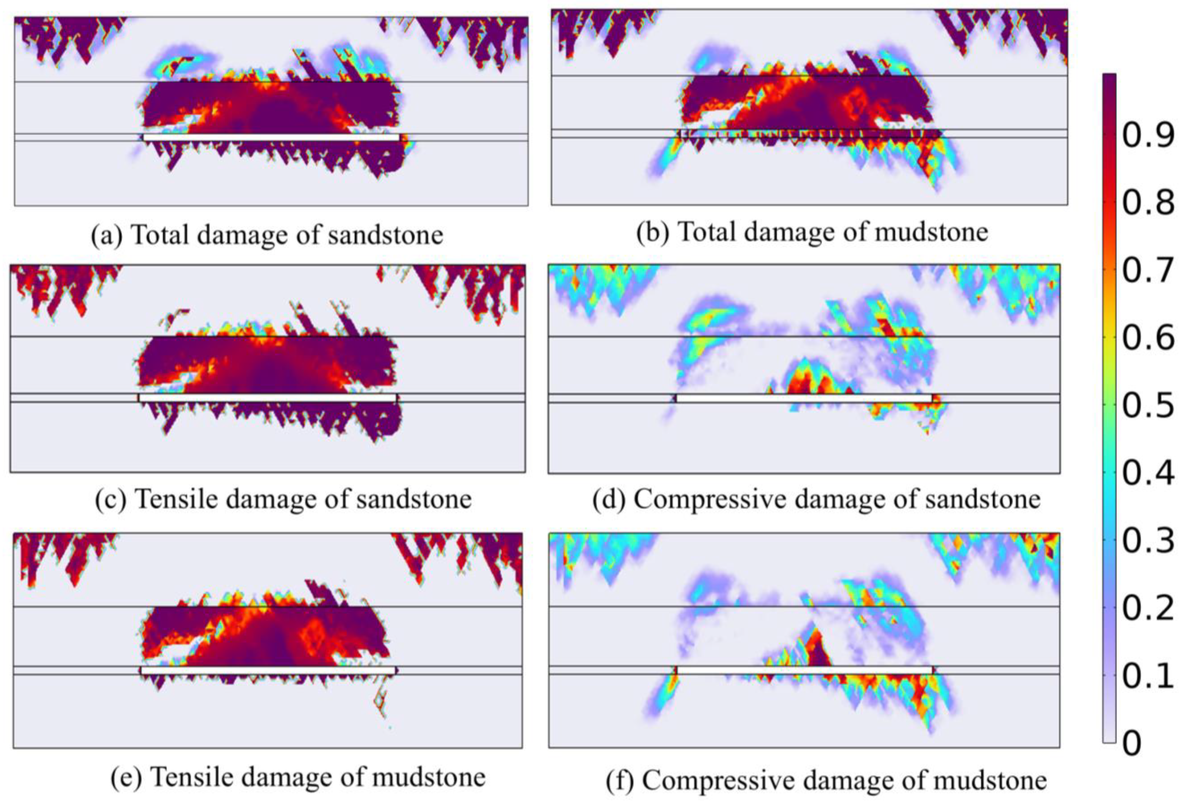
The differences in pore structure and mechanical strength among various lithologies result in distinctly different failure modes under the coupled action of “stress and seepage.” Typical sandstone (brittle, high permeability) and mudstone (plastic, low permeability) from the Shendong mining area were selected as floor lithologies for numerical simulation, with the comparative results shown in Figure 11. The comparative analysis indicates that lithological differences significantly control the maximum depth and spatial distribution of floor damage.
For the sandstone floor (Figure 11a,c), it exhibits significant characteristics of “brittle tensile cracking.” Due to the high elastic modulus of sandstone, the damage is primarily dominated by deep tensile stress, forming multiple parallel, “knife-like” vertical penetrating fractures, with a maximum failure depth reaching 28.11 m. Notably, a comparison between Figure 11c,d reveals that tensile damage penetrates the entire failure zone, serving as the dominant factor inducing the formation of deep seepage channels.
In contrast, the mudstone floor (Figure 11b,f) displays distinct characteristics of “plastic shear failure” and “localized failure.” Using the damage variable D > 0.5 as the threshold for rock mass failure, it can be observed that the damage in mudstone is primarily localized within the stress concentration zones beneath the coal wall and the open-off cut. This damage is dominated by compressive-shear failure and, unlike the sandstone case, fails to form extensive damage in the central area of the goaf. It is precisely this damage distribution morphology—characterized by “localized compressive-shear at the edges and overall integrity in the center”—that effectively severs the vertical extension and horizontal connection of seepage channels toward the deep strata. To quantitatively substantiate the superiority of mudstone as a water barrier, the absolute permeability evolution of the two lithologies under a 1.0 MPa storage pressure was extracted and compared. Initially, the mudstone floor possesses an intrinsically low permeability of 1.0 × 10⁻¹⁷ m2, which is seven orders of magnitude lower than that of the sandstone floor (3.04 × 10⁻¹⁰ m2). Under the high-pressure driving force, the widespread brittle tensile fractures in the sandstone act as preferential flow paths, inducing a massive surge in permeability. Its maximum permeability increases by 167 times, reaching an absolute value of up to 5.08 × 10⁻⁸ m2, effectively forming a fully connected macroscopic seepage channel. In stark contrast, the permeability mutation in the mudstone floor is highly restricted by its plastic yielding and localized damage characteristics. Its maximum permeability merely increases by 135 times, bringing the absolute value to only 1.35 × 10⁻¹⁵ m2. This quantitative value structurally remains within the strict safety threshold of an impermeable aquiclude. More importantly, the localized moderate-permeability zones in the mudstone remain completely isolated beneath the solid coal walls, failing to form a continuous vertical leakage pathway in the central goaf.
Therefore, judging from both the damage morphology and the quantitative permeability evolution, the overall seepage resistance performance of the mudstone floor is significantly superior to that of sandstone, making it more suitable as an impermeable carrier for underground reservoirs. Conversely, for sandstone floors, focus must be placed on preventing and controlling the risk of deep seepage channel activation triggered by brittle tensile cracking and high-pressure hydraulic wedging.

4.3.2. Influence of Burial Depth on Floor Damage Depth

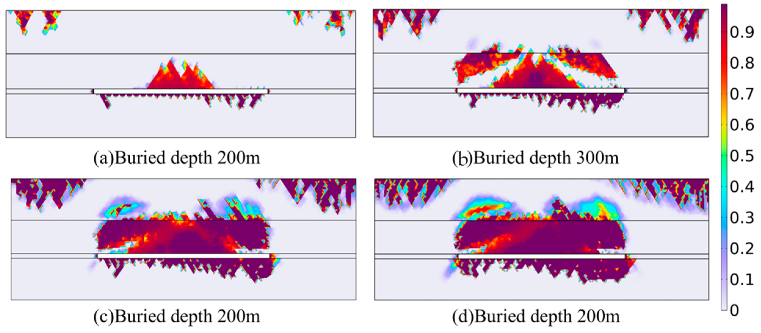
The occurrence depth of a coal seam directly determines the in-situ stress level and the mechanical response characteristics of the surrounding rock. To investigate the impact of different in-situ stress environments on the stability of the underground reservoir floor, four working conditions with burial depths of 200 m, 300 m, 400 m, and 500 m were set for comparative analysis, with results shown in Figure 12. The simulation results indicate that as the burial depth increases, the evolution of floor damage exhibits a significant non-linear expansion trend.
Under the shallow burial condition (200 m), the vertical and horizontal in-situ stresses on the floor rock mass are relatively low. Failure is primarily dominated by localized tension induced by mining unloading. The damage zone is concentrated in the shallow surface layer in the middle of the goaf, with a maximum failure depth of only 14.9 m, exhibiting a relatively flat and unconnected morphology. When the burial depth increases to 300 m, although the damage range expands and the depth increases to 21.9 m, the overall extent remains within a controllable range.
However, when the burial depth further breaks through to 400 m and 500 m, the deep high-stress environment causes the floor rock mass to be in a state of extremely high deviatoric stress. At this point, once the reservoir is impounded, the pore water pressure offsets the effective confining pressure, easily triggering compressive-shear mixed failure in the deep rock mass. The contour map clearly shows that under the 500 m burial depth, the floor damage zone not only expands significantly in breadth but also shows a trend of intruding into deeper strata. The maximum failure depth surges to 38.6 m, forming a wide and connected macroscopic failure zone.
This implies that when constructing underground reservoirs in deep mines, relying solely on the self-bearing capacity of the floor strata may not be sufficient to resist the dual effects of high water pressure and high in-situ stress. Therefore, priority must be given to preventing the risk of sudden floor water-conducting channel breakthroughs caused by deep shear slip instability.

4.3.3. Influence of Mining Height on Floor Damage Depth

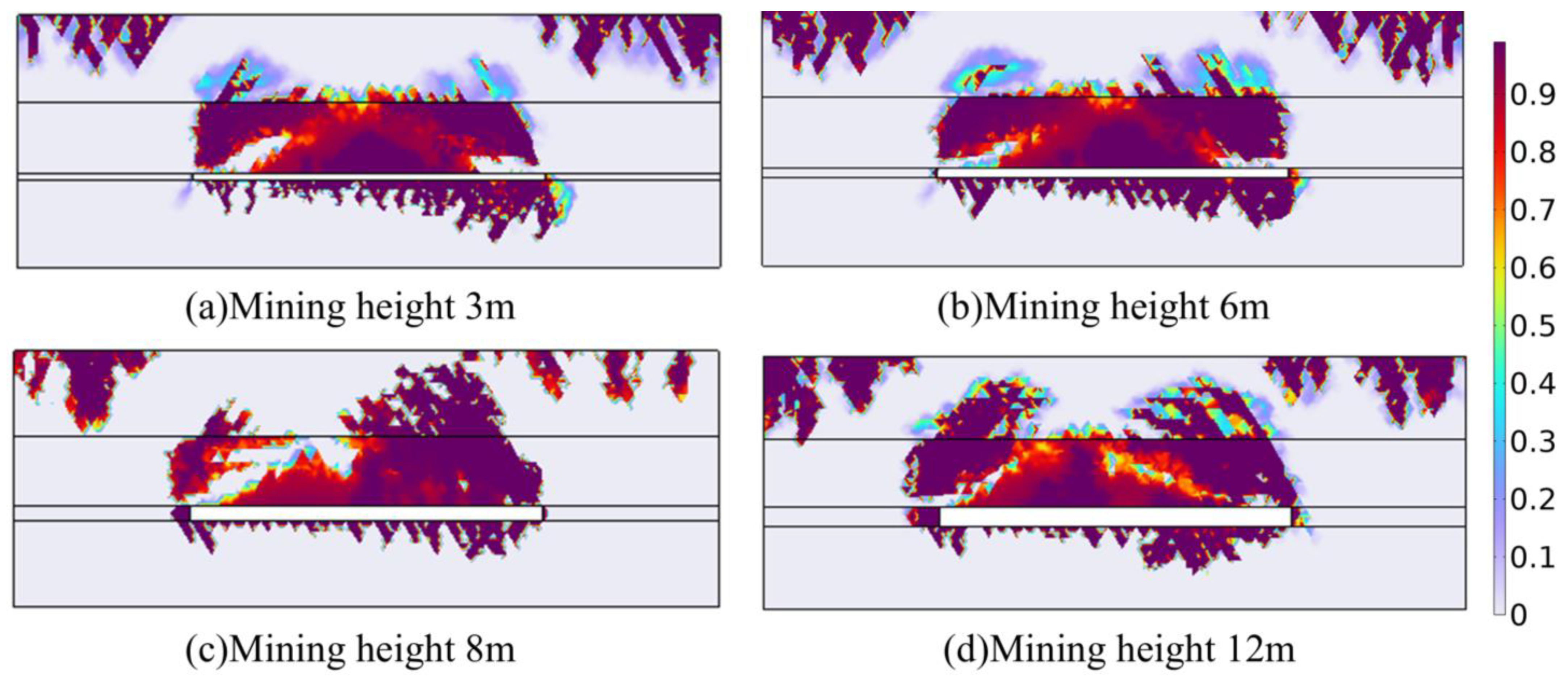
Figure 13 illustrates the final distribution morphology of the floor damage field under varying mining heights. Comparative analysis of the simulation results reveals that although the height of the caving zone in the overlying strata exhibits a significant linear growth trend with increasing mining height, the variation in floor damage depth displays a distinct “blunting” (insensitivity) characteristic. The maximum failure depth remains basically within a certain range and does not expand drastically with the enlargement of the extraction space.
Investigating the underlying mechanical mechanism, floor damage and failure primarily originate from the unloading rebound effect and interlayer tensile slip triggered by the removal of the vertical load above the goaf following coal seam excavation. For the floor strata interface, whether mining a 3 m or 12 m thick coal seam, the change in mechanical boundary conditions is essentially the complete release of vertical stress. This “equivalent unloading” effect causes the tensile failure potential of the shallow floor to tend toward saturation even at smaller mining heights.
Furthermore, according to strata pressure theory, the depth of the floor plastic failure zone is mainly controlled by the inclined length of the working face and the in-situ stress level, rather than the vertical height of the mining space. Under the premise that the advancing length and width of the working face remain constant, simply increasing the mining height does not alter the dominant spatial geometric parameters of floor stress. Therefore, it does not induce larger-scale shear slip or tensile fracturing in deep rock strata.
This pattern holds significant engineering application value. It indicates that when constructing underground reservoirs under ultra-thick coal seam mining conditions, although increasing the mining height significantly expands the water storage capacity, it does not significantly deteriorate the deep water-barrier performance of the floor. This validates the geological safety and technical feasibility of utilizing large mining height goafs for underground water storage.

4.4. Sensitivity Analysis of Key Controlling Factors for Floor Failure

4.4.1. Construction of Sensitivity Evaluation Model

The damage and failure of the floor in underground coal mine reservoirs is a complex non-linear process controlled by the coupling of multiple physical fields. The key influencing factors involved include water storage pressure, burial depth, floor lithology, and coal mining height. Since the physical dimensions (units) of these influencing factors differ and their value ranges vary significantly, directly comparing their absolute impact on failure depth lacks a scientific and unified basis.
To address this, a dimensionless sensitivity coefficient, S, is introduced as a quantitative evaluation index. The aim is to eliminate dimensional effects and accurately identify the dominant sensitive sources that trigger floor activation. The sensitivity coefficient S is defined as the degree of response of the rate of change in floor failure depth to the rate of change of a specific factor. Its calculation model is as follows:
S k = Δ H d / H d 0 Δ X k / X k 0
In the formula: S k is the sensitivity coefficient of the k-th factor. The larger the value of S k , the more sensitive the depth of the floor failure is to the fluctuation of this factor; X k 0 and Δ X k are the baseline value and the change of the k-th influencing factor, respectively; H d 0 and Δ H d are the depth of the floor failure under the baseline working condition and the corresponding change, respectively.
To systematically evaluate the impact of each variable, a formal classification standard for sensitivity levels is established based on the absolute value of the sensitivity coefficient |S|. Referencing standard sensitivity evaluation practices in engineering geomechanics and aligning with the data distribution characteristics of this model, the sensitivity is explicitly classified into three distinct levels: weak sensitivity when 0 ≤ |S| < 0.5, moderate sensitivity when 0.5 ≤ |S| < 1.0, and strong sensitivity when |S| ≥ 1.0. This unified classification standard, which evaluates the relative percentage response of the failure depth to parameter variations, provides a robust and clear quantitative framework for the subsequent sections, ensuring that the identification of the dominant controlling factors is strictly grounded in a defined mathematical boundary.

4.4.2. Single-Factor Sensitivity Analysis

(1) Sensitivity Analysis of Water Storage Pressure
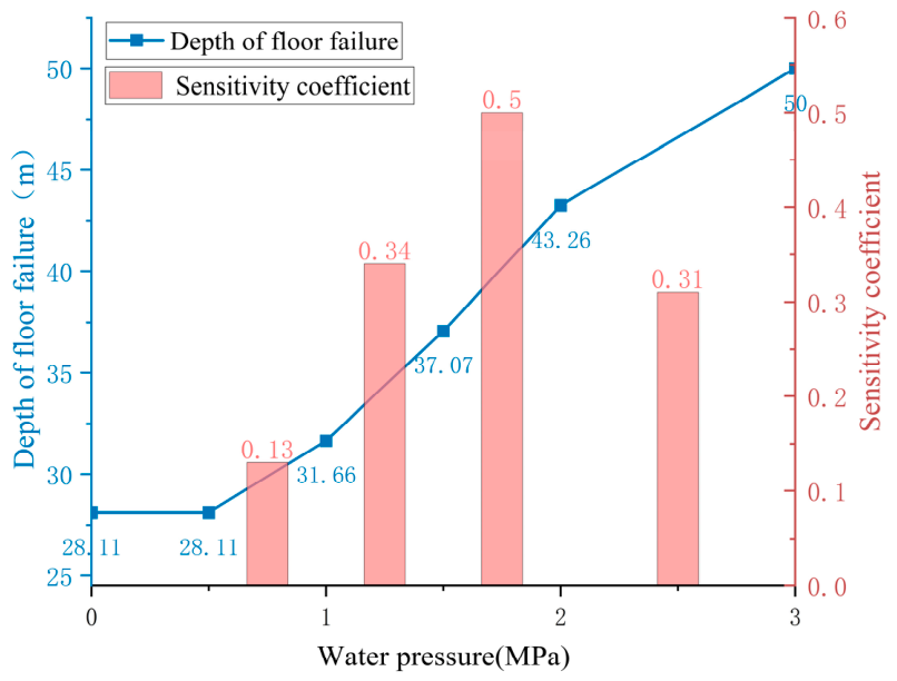
Water storage pressure acts as the fundamental driving force for the initiation and propagation of floor damage toward deeper levels. As illustrated in the Figure 14, the floor failure depth exhibits distinct “three-stage” non-linear evolutionary characteristics with increasing water pressure: During the stable phase (0–0.5 MPa), the failure depth remains constant at 28.11 m, indicating that the low water pressure has not yet overcome the effective confining pressure of the rock mass, and the floor remains in a state of elastic compression. During the fracture initiation phase (0.5–1.0 MPa), the failure depth increases only slowly to 31.66 m, yielding a very low sensitivity coefficient of 0.13. However, once the pressure exceeds the 1.0 MPa threshold and enters the accelerated breakthrough phase, the slope of the curve increases abruptly; the failure depth climbs to 37.07 m at 1.5 MPa, surges to 43.26 m at 2.0 MPa, and ultimately reaches 50 m at 3.0 MPa. Sensitivity analysis further reveals that the sensitivity coefficient escalates progressively after 1.0 MPa, reaching 0.34 in the 1.0–1.5 MPa range and peaking at 0.5 within the 1.5–2.0 MPa interval. This validates that 1.0 MPa is not merely a statistical tipping point, but a critical mechanical threshold where the hydrostatic pressure overcomes the effective confining stress, actively facilitating the ‘hydraulic wedging’ propagation of fracture.
(2) Sensitivity Analysis of Burial Depth
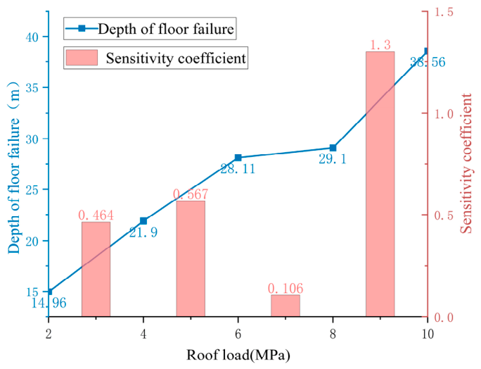
Burial depth governs the foundational in-situ stress environment of the floor rock mass. As illustrated in the Figure 15, as the roof load increases from 2 MPa to 10 MPa, the floor failure depth increases in an approximately linear manner from 14.96 m to 38.56 m, demonstrating a significant positive correlation.
However, the evolution of the sensitivity coefficient reveals the potential risks associated with deep mining. In the shallow burial stage (load < 8 MPa), the sensitivity coefficient fluctuates at a low-to-moderate level of 0.1–0.6, where floor failure is primarily dominated by the mining unloading effect. Conversely, when the load surpasses 8 MPa, entering the deep high-stress zone, the sensitivity coefficient rises steeply to 1.3, reaching its peak value.
This indicates that the deep rock mass is already in a critical yield state characterized by high deviatoric stress, exhibiting extremely strong sensitivity to variations in in-situ stress. Consequently, when constructing underground reservoirs in deep high-stress zones, the floor rock mass is more susceptible to damage and failure. Therefore, a greater thickness of the safety aquiclude must be reserved to withstand the risk of deep failure induced by high confining pressure.
(3) Sensitivity Analysis of Coal Mining Height
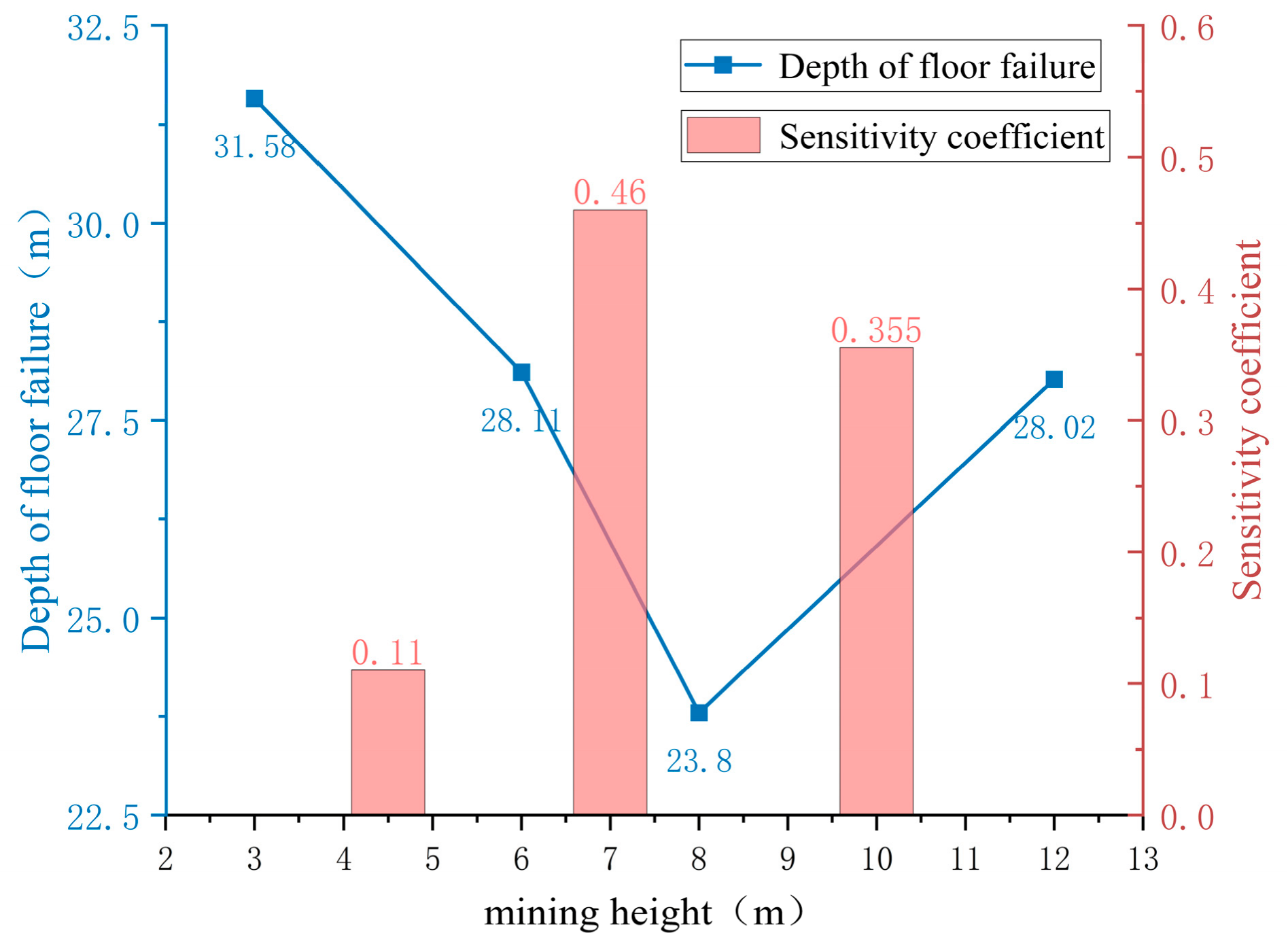
Distinct from the significant controlling effects of water pressure and burial depth, the variation in mining height exhibits a “weak sensitivity” characteristic regarding deep floor failure. As shown in Figure 16, as the mining height increases from 3 m to 12 m, the floor failure depth does not demonstrate continuous deterioration. Instead, it presents a fluctuating pattern of “initial decrease followed by a slight increase,” with values consistently concentrated within the limited range of 24 m to 31 m.
Calculations indicate that its sensitivity coefficient ranges from 0.11 to 0.46. This suggests that, under the premise of a fixed working face length, changes in the vertical height of the extraction space primarily alter the roof caving morphology but have a relatively minor impact on floor damage and failure. However, it is worth noting that this relatively weak sensitivity is closely tied to the specific spatial geometry of the simulated working face. Since the model represents a typical fully mechanized extraction scenario with a sufficient panel width, the macro-stress redistribution is predominantly governed by the burial depth and lithology. If the spatial geometry were significantly altered—such as in sub-critical extraction with narrower panel widths, steeply dipping seams, or ultra-thick coal seam mining—the stress arching mechanism above the goaf would change considerably. Under those specific geometrical configurations, the marginal effect of the mining height on the floor stress concentration could be notably amplified. Therefore, while mining height acts as a secondary driving factor for the near-horizontal, adequately wide panels analyzed in this study, its potential impact under different geometric boundary conditions still warrants careful evaluation in engineering practice.
(4) Sensitivity Analysis of Floor Lithology
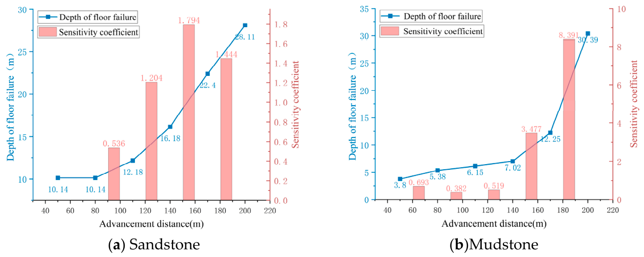
Floor lithology and its mechanical attributes significantly alter the spatiotemporal propagation path of damage. As illustrated in Figure 17, a comparison of failure depths between sandstone and mudstone at different advancing distances reveals the following:
The failure depth of the sandstone floor exhibits relatively uniform linear growth with the advancing distance, manifesting as progressive brittle tensile cracking, with a peak sensitivity coefficient of 1.79.
In contrast, the mudstone floor, due to its relatively higher tensile strength, exhibits a smaller failure depth during the initial mining stage and displays certain ductile characteristics. However, when the advancing distance reaches 200 m, the failure depth surges to 31 m, dominated by compressive damage, with the sensitivity coefficient reaching as high as 8.39.
This indicates that mudstone is more susceptible to massive shear slip instability under large-scale mining disturbances, resulting in a late-stage sensitivity coefficient (8.39) even higher than that of sandstone. However, it is important to note that this high sensitivity primarily reflects the rapid volumetric expansion of its plastic yield zone (failure depth), rather than a deterioration in impermeability. As analyzed in Section 4.3.1, the extensive deep damage in mudstone is overwhelmingly dominated by compressive-shear yielding. Because compressive-shear fractures remain tightly closed under pressure—unlike the open, highly permeable tensile fractures typical in sandstone—the yielded mudstone effectively suppresses any exponential surge in seepage. Therefore, the extremely high sensitivity of mudstone highlights its structural vulnerability to macroscopic deformation, yet this does not negate its overall superiority as a relatively impermeable water barrier.

4.4.3. Comprehensive Sensitivity Evaluation and Engineering Recommendations

Quantitative analysis based on the dimensionless sensitivity coefficient reveals significant differentiated control mechanisms of key factors on floor damage:
The geological occurrence environment (burial depth and lithology) exhibits substantial “strong sensitivity” control characteristics. particularly under conditions of deep high in-situ stress and soft mudstone, the sensitivity coefficients remain at the highest levels across the entire field. This indicates that the geological condition of “deep depth + soft rock” serves as the innate foundation determining whether macroscopic instability occurs in the floor, and special attention must be paid to this during reservoir site selection.
Water storage pressure presents a unique “threshold triggering” characteristic. Although its sensitivity value is influenced by the specific range, acting as the sole dynamic control variable, it can induce an order-of-magnitude mutation in permeability through “hydraulic wedging” once it exceeds the 1.0 MPa threshold. Therefore, it serves as the core measure for preventing aquiclude failure during the operational period.
In contrast, coal mining height displays a significant “weak sensitivity” characteristic, confirming that the “equivalent unloading” induced by increased mining height does not significantly deteriorate the deep water-barrier performance of the floor.
Based on these findings, it is recommended to adopt a “hierarchical collaborative strategy” in underground reservoir engineering practice: fully utilize large mining heights to expand storage capacity in the design phase, prioritize avoiding deep soft-rock high-risk areas during site selection, and ensure strict hydraulic isolation during operation. Regarding the upper safety limits of storage pressure, our model identifies 1.0 MPa as the universal activation threshold for deep floor damage. However, in actual practice, provided that the reservoir water surface is not hydraulically connected to overlying aquifers, the maximum storage pressure is physically constrained by the extraction height and will inherently remain far below this 1.0 MPa condition. Therefore, the primary engineering directive must be to completely prevent any uncontrolled connection with upper aquifers (e.g., via fault zones or penetrating fractures), which could otherwise introduce extreme hydrostatic pressures that trigger sudden brittle tensile cracking in sandstone floors or large-scale shear instability in mudstone floors. Furthermore, to determine the minimum safety aquiclude thicknesses and prevent reservoir leakage, a complete impermeable buffer zone must be reserved beneath the maximum failure depth. By adding a 10–15 m intact buffer zone to the simulated maximum failure depths under different in-situ stresses, we recommend a minimum safety aquiclude thickness of 30–35 m for shallow-to-medium burial depths (200–300 m). For deep burial conditions (400–500 m) where deep compressive-shear failure dominates, the minimum reserved thickness must be substantially increased to 50–55 m to ensure long-term stability against high ground stress. Ultimately, this quantified strategy aims to maximize water resource utilization efficiency while fundamentally ensuring geological safety.

5. Conclusions

Addressing the floor stability of underground coal mine reservoirs in western mining areas, this paper established a fully coupled stress-damage-seepage model considering rock heterogeneity. The study systematically revealed the damage evolution mechanism and key controlling factors under coupled mining and water pressure. The main conclusions are as follows:
(1) Mining-induced unloading acts as the mechanical prerequisite for initial floor damage, while water storage pressure serves as the fundamental driving force for its deep propagation. Specifically, before the water pressure reaches the critical threshold of 1.0 MPa, the floor damage remains essentially dormant and unchanged. However, once this 1.0 MPa threshold is exceeded, a significant “hydraulic wedging” effect is activated. This abruptly shifts the failure mode from shallow discrete fracturing to deep penetrating failure, triggering an order-of-magnitude surge in permeability and creating preferential leakage channels that connect the reservoir to deep strata.
(2) The geological environment governs the damage patterns and failure paths. Lithologically, brittle sandstone is highly susceptible to deep tensile stress, leading to progressive cracking and macroscopic seepage channels. In contrast, mudstone possesses a significantly lower intrinsic permeability. Even when subjected to large-scale mining disturbances, its localized plastic shear characteristics effectively restrict permeability mutations, granting it superior water-barrier performance compared to sandstone. Structurally, burial depth determines the in-situ stress level, with floor damage showing a non-linear expansion as depth increases. Under deep high-stress and high-water-pressure conditions, the failure mechanism shifts to deep compressive-shear mixed failure, resulting in a significantly expanded macroscopic failure zone.
(3) Quantitative sensitivity analysis reveals differentiated control mechanisms. Geological conditions (burial depth and lithology) exhibit “strong sensitivity,” serving as the innate basis for stability. Water pressure displays a “threshold triggering” feature, acting as the active factor for permeability mutation. Meanwhile, mining height shows “weak sensitivity” due to an “equivalent unloading” effect, confirming that increasing mining height does not significantly deteriorate deep floor stability. These findings validate the geological safety of constructing underground reservoirs in ultra-thick coal seams. Consequently, engineering practice should prioritize avoiding deep soft-rock areas during site selection and strictly controlling operational water level thresholds to ensure long-term safety.

Author Contributions

Conceptualization, J.Z.; methodology, J.Z.; software, X.Z.; validation, D.X. and F.W.; formal analysis, X.Z.; investigation, D.X. and X.W.; resources, X.W.; data curation, D.X.; writing—original draft preparation, X.Z.; writing—review and editing, F.W.; visualization, X.Z.; supervision, J.Z.; funding acquisition, J.Z. All authors have read and agreed to the published version of the manuscript.

Funding

This research was funded by the Open Fund of State Key Laboratory of Water Resource Protection and Utilization in Coal Mining, grant number GJNY-23-37-06.

Data Availability Statement

The original contributions presented in this study are included in the article. Further inquiries can be directed to the corresponding author.

Acknowledgments

The authors also thank the editor and anonymous reviewers for their efforts. During the preparation of this manuscript, the authors used Gemini 1.5 Pro (Google) for the purposes of visually refining Figure 1. The authors have reviewed and edited the output and take full responsibility for the content of this publication.

Conflicts of Interest

Author Xiaohang Wan was employed by the company Bulianta Coal Mine, Guoneng Shendong Coal Group Co., Ltd. and Author Fengchen Wang was employed by the company Halagou Coal Mine, China Energy Shendong Coal Group Co., Ltd. The remaining authors declare that the research was conducted in the absence of any commercial or financial relationships that could be construed as a potential conflict of interest.

References

  1. Gu, D.Z. Theory framework and technological system of coal mine underground reservoir. J. China Coal Soc. 2015, 40, 239–246. [Google Scholar] [CrossRef]
  2. Xiuchang, S.H.I. Research progress and prospect of underground mines in coal mines. Coal Sci. Technol. 2023, 50, 216–225. [Google Scholar] [CrossRef]
  3. Huang, X.Y.; Wang, S.J.; Wang, X.P. Variation characteristics of atmospheric precipitable water in Northwest China from 1960 to 2015. Meteorol. Mon. 2018, 44, 1191–1199. [Google Scholar]
  4. Wu, Q.; Liu, H.L.; Zeng, Y.F.; Liu, X. Current status, existing problems and countermeasures of green mine construction in China. Green Mine 2023, 1, 25–32. [Google Scholar] [CrossRef]
  5. Wang, F.T.; Sun, N.; Zhang, C.; Guo, Z.; Dou, F. Research progress and prospect on water purification mechanism of water-rock interaction in mine goaf reservoir. Green Mine 2024, 2, 246–257. [Google Scholar]
  6. Kang, H.P.; Li, Q.S.; Zhang, Y.J.; Guo, J.; Liu, P. Current status and prospect of green mining and ecological restoration technology for coal mines in China. Green Mine 2023, 1, 1–24. [Google Scholar] [CrossRef]
  7. Liu, Z.Y.; Liu, X.L. Theoretical analysis of dissipative structure and damage model for rock deformation and failure process. Chin. J. Undergr. Space Eng. 2023, 19, 51–60+78. [Google Scholar] [CrossRef]
  8. Yao, W.; Yu, J.; Liu, X.; Zhang, Z.; Feng, X.; Cai, Y. Experimental and theoretical investigation of coupled damage of rock under combined disturbance. Int. J. Rock Mech. Min. Sci. 2023, 164, 105355. [Google Scholar] [CrossRef]
  9. Ru, W.; Hu, S.; Zhou, A.; Luo, P.; Gong, H.; Zhang, C.; Zhou, X. Study on creep characteristics and nonlinear fractional-order damage constitutive model of weakly cemented soft rock. Rock Mech. Rock Eng. 2023, 56, 8061–8082. [Google Scholar] [CrossRef]
  10. Lu, T.; Wu, H.; Yin, S.; Xu, X. Study of Rock Damage Constitutive Model Considering Temperature Effect Based on Weibull Distribution. Appl. Sci. 2024, 14, 3766. [Google Scholar] [CrossRef]
  11. Hu, J.; Shi, J.; Zhang, S.; Yang, J. Impact of a damage-based cohesion degradation–friction angle reinforcement model on tunnel surrounding rock stability. Can. Geotech. J. 2025, 62, 1–20. [Google Scholar] [CrossRef]
  12. Bi, J.; Ning, L.; Zhao, Y.; Wu, Z.; Wang, C. Analysis of the Microscopic Evolution of Rock Damage Based on Real-Time Nuclear Magnetic Resonance. Rock Mech. Rock Eng. 2023, 56, 3399–3411. [Google Scholar] [CrossRef]
  13. Chen, J.X. Study on the Evolution Law of Mechanical Damage and Seepage Characteristics of Limestone Under Hydro-Mechanical Coupling. Master’s Thesis, Taiyuan University of Technology, Taiyuan, China, 2024. [Google Scholar] [CrossRef]
  14. Yu, X.G. Study on failure Depth of Damaged Floor in Stope. Ph.D. Thesis, Shandong University of Science and Technology, Qingdao, China, 2011. [Google Scholar]
  15. Liu, H.; Li, X.; Liu, X.; Sun, Y.; Yang, Z.; Zhong, Y. Rule Study on the Risk of Floor Water Inrush Based on the Plate Model Theory. Sustainability 2023, 15, 7844. [Google Scholar] [CrossRef]
  16. Chen, Y.; Xu, J.; Cao, Q.; Rao, H.; Cui, M.; Zhang, Q.; Peng, S. Experimental Study on Mechanical and Strain Localisation Behaviour of Sandstone Under Seepage–Stress Coupling. Rock Mech. Rock Eng. 2023, 56, 8457–8470. [Google Scholar] [CrossRef]
  17. Zhu, W.C.; Wei, C.H.; Tian, J.; Yang, T.; Tang, C. Preliminary study on thermo-hydro-mechanical coupling model and its application in rock damage process. Rock Soil Mech. 2009, 30, 3851–3857. [Google Scholar] [CrossRef]
  18. Yang, L.; Li, X.Q. Study on variation law of seepage field in goaf based on stress-seepage-damage coupling. Value Eng. 2023, 42, 97–100. [Google Scholar] [CrossRef]
  19. Shao, J.; Zhang, W.; Wu, X.; Lei, Y.; Wu, X. Rock Damage Model Coupled Stress-Seepage and Its Application in Water Inrush from Faults in Coal Mines. ACS Omega 2022, 7, 13604–13614. [Google Scholar] [CrossRef] [PubMed]
  20. Shao, J.; Zhang, Q.; Zhang, W. Evolution of mining-induced water inrush disaster from a hidden fault in coal seam floor based on a coupled stress–seepage–damage model. Geomech. Geophys. Geo-Energy Geo-Resour. 2024, 10, 78. [Google Scholar] [CrossRef]
  21. Xu, Z.M.; Xiong, S.J.; Yuan, H.Q.; Sun, Y.; Han, Y.; Chen, T.; Lu, W. Simulation test on structural evolution and damage deterioration mechanism of water-immersed boundary coal pillar in abandoned goaf. J. China Coal Soc. 2025, 50, 1100–1114. [Google Scholar] [CrossRef]
  22. Li, A.; Ji, B.N.; Mu, Q.; Wang, M.; Yu, Z.; Deng, W.; Li, H.; Han, T.; Guo, Z. Study on failure mechanism and application of composite structural floor in deep coal-rock stratum. Chin. J. Rock Mech. Eng. 2022, 41, 559–572. [Google Scholar] [CrossRef]
  23. Zhang, J.; He, G.; Yang, S.; Fu, H.; Zhao, J.; Wang, F. Enhancing in-situ coal-gangue identification in LTCC mining via secondary surfactant intervention and infrared thermography. Int. J. Min. Sci. Technol. 2026, 36, 1249–1274. [Google Scholar] [CrossRef]
  24. Li, S.; Zhang, Q.; Wu, S.; Liu, Z. Study on the critical damage threshold of homogeneous sandstone and its validation by SHPB tests. Trans. Beijing Inst. Technol. 2017, 37, 807–812+823. [Google Scholar] [CrossRef]
  25. Liu, W.; Pan, Q.; Chen, B.; Zhang, D.; Lin, H. Study on the stress-seepage coupling model of rock structure based on damage evolution. In Proceedings of the 19th Northern Seven Provinces and Cities Mechanics Society Academic Conference, Chengde, China, 4–7 August 2023; pp. 257–270. [Google Scholar]
  26. Zhang, J.; Cheng, D.; Wang, J.; Yang, S.; Wan, X.; Li, X. Improving recovery in sublevel top coal caving mining by using partially reverse drawing technique. Int. J. Min. Sci. Technol. 2024, 34, 1655–1676. [Google Scholar] [CrossRef]
  27. Jiang, Q. Measurement of mining-induced failure depth of coal seam floor in deep working face. Coal Geol. Explor. 2009, 37, 30–33. [Google Scholar]
Figure 1. Schematic diagram of distributed underground reservoir in coal mine.
Water 18 01688 g001
Figure 2. Seepage-Stress-Damage Coupling Relationship Diagram.
Water 18 01688 g002
Figure 3. Mining Face Extraction Model.
Water 18 01688 g003
Figure 4. Heterogeneous Distribution of Elastic Modulus and Tensile Strength.
Water 18 01688 g004
Figure 5. Contour map of vertical stress distribution on the roof and floor of coal seams at different advancing distances (Unit: Pa).
Water 18 01688 g005
Figure 6. Stress changes along the strike of the coal seam floor at different advancement distances.
Water 18 01688 g006
Figure 7. Vertical Displacement Curve of the Mining Coal Seam Floor.
Water 18 01688 g007
Figure 8. Cloud Map of Damage Evolution on the Coal Seam Floor at Different Advancing Distances.
Water 18 01688 g008
Figure 9. Cloud map of floor damage evolution under different water storage pressures.
Water 18 01688 g009
Figure 10. Cloud map showing the distribution of increased permeability multiples of the floor under different water pressures.
Water 18 01688 g010
Figure 11. Comparison of Damage Evolution Cloud Maps of Different Lithology Floors.
Water 18 01688 g011
Figure 12. Cloud map of base slab damage evolution under different burial depths.
Water 18 01688 g012
Figure 13. Cloud map of floor damage evolution under different mining heights.
Water 18 01688 g013
Figure 14. Variation and Sensitivity Analysis of floor Failure Depth with Water Storage Pressure.
Water 18 01688 g014
Figure 15. Variation of Floor Slab Failure Depth with Roof Load and Sensitivity Analysis.
Water 18 01688 g015
Figure 16. Depth of Floor Failure Variation with Mining Height and Sensitivity Analysis.
Water 18 01688 g016
Figure 17. Differences in the evolution of floor failure depth with advancing distance for different rock types.
Water 18 01688 g017
Table 1. Specific mechanical and permeability parameters of the model.
Rock Strata NameElastic Modulus E/GPaPoisson’s RatioDensity/(kg/m3)Tensile Strength/MPaCompressive Strength/MPaInitial PorosityPermeability Coefficient/m2
Overburden II18.90.2223205700.155 × 10−14
Overburden I12.60.2824503.5370.158 × 10−12
Coal Seam12.50.3214500.32150.154 × 10−11
Sandstone floor140.2525101.6340.33.04 × 10−10
Mudstone Floor9.50.2424202.8340.151 × 10−17
Disclaimer/Publisher’s Note: The statements, opinions and data contained in all publications are solely those of the individual author(s) and contributor(s) and not of MDPI and/or the editor(s). MDPI and/or the editor(s) disclaim responsibility for any injury to people or property resulting from any ideas, methods, instructions or products referred to in the content.