Review

Advances in Laser-Induced Acoustic Technology for Underwater Detection

1
College of Mathematics and Physics, Qingdao University of Science and Technology, Qingdao 266061, China
2
Laoshan Laboratory, Qingdao 266061, China
3
College of Precision Instrument and Optoelectronic Engineering, Tianjin University, Tianjin 300072, China
4
College of Physical Science and Technology, Jinan University, Jinan 250024, China
*
Authors to whom correspondence should be addressed.
Water 2025, 17(22), 3285; https://doi.org/10.3390/w17223285
Submission received: 18 October 2025 / Revised: 4 November 2025 / Accepted: 11 November 2025 / Published: 17 November 2025
(This article belongs to the Topic Advances in Hydrological Remote Sensing)

Abstract

Laser-induced acoustic (LIA) underwater detection, as a next-generation sensing paradigm, combines high spatial resolution, rapid temporal response, and cross-medium detection capability, positioning it as a strategically significant technology in marine resource exploration, military security, and ocean environmental monitoring. The fundamental principles underlying LIA technology are systematically examined, together with recent advances in representative experimental systems and critical enabling techniques. The characteristics of the laser–acoustic transmission channel are comprehensively investigated, and the mechanisms through which laser parameters modulate the properties of acoustic signals are rigorously elucidated. Moreover, several challenges hindering practical applications are underscored, including laser energy attenuation, interference arising from complex underwater environments, and the comparatively high cost of equipment. Finally, future research directions are outlined, encompassing the development of high-efficiency laser sources, multimodal integrated sensing strategies, intelligent signal processing algorithms, and improved environmental adaptability. These efforts are intended to provide theoretical underpinnings for the continued advancement and broader application of LIA-based underwater detection technologies.

1. Introduction

Conventional underwater detection technologies rely on electromagnetic waves and mechanical sonar systems [1]. However, electromagnetic waves suffer from strong attenuation in seawater with an attenuation coefficient of approximately 103 dB/km [2], while sonar systems face limitations such as low transduction efficiency, narrow bandwidth, and susceptibility to mechanical disturbances. LIA technology generates broadband acoustic waves through the interaction between high-energy pulsed lasers and water media. By leveraging an optical-to-acoustic energy conversion mechanism, LIA enables non-contact acoustic source excitation and circumvents the immersion-related disturbances inherent to traditional sonar, offering an innovative solution for deep-sea exploration [3,4,5]. A comparison of the advantages and disadvantages, as well as the detection parameters, of various underwater detection technologies is presented in Table 1. Overall, different underwater sensing technologies present distinct trade-offs across range, resolution, environmental adaptability, and system cost, among which LIA demonstrates clear advantages in handling complex sea states, achieving high resolution, and enabling long-range detection. The core advantages of this technology are reflected in three aspects. First, the integration of air-optical and water-acoustic dual channels utilizes the low-loss transmission of lasers in the atmosphere and the low attenuation of acoustics in water, substantially extending long-range detection. Second, the broadband acoustic source supports high-resolution target recognition, enabling the detection of millimeter-scale underwater structures. Third, by tuning laser parameters such as single-pulse energy and pulse duration, the spectral characteristics of the generated acoustic signals can be tailored to adapt to complex marine environments. With an underwater transmission range exceeding one hundred meters, LIA provides technological support for submarine communication, mineral exploration, and ecological environment monitoring. Moreover, the continued development of this technology is expected to advance the intelligence of marine equipment and diversify detection modalities, carrying profound implications for safeguarding maritime interests, strengthening national defense security, and fostering marine economic growth.
Research on LIA technology began in 1962, when White and Prokhorov first reported the phenomenon of acoustic wave generation by pulsed lasers in condensed media. In 1973, they experimentally revealed the spectral and spatial distribution characteristics of laser-generated acoustic signals [42]. From 1980 onward, research in this field entered a stage focused on technical validation and system development. The Hickman team in the United States made a series of pioneering contributions: in 1980, they achieved underwater detection at a depth of 20 m using a CO2 laser, providing the first experimental verification of the feasibility of laser-induced underwater detection [43]; in 1981, they developed the Experimental Laser/Acoustic System (ELAS), which enabled depth sounding in turbid shallow waters using a CO2 laser, and extended the system’s applications to submarine communication and thermocline detection [44]; in 1987, they demonstrated 1 m ice thickness measurement using a 6.5 J laser and proposed a linear relationship model between ice thickness and laser energy [45]; and by 1990, they replaced the CO2 laser with a Nd:YAG laser to enhance the sensitivity of ice-layer detection [44].
With the advancement of technology, increasing attention has been devoted to multiphysics coupling research in LIA since 2015, accelerating its transition toward practical applications. In 2016, Bidin et al. established a quantitative relationship between acoustic velocity/amplitude and hydrocarbon concentration in water based on laser-induced breakdown (LIB) technology, introducing a novel approach to pollutant monitoring [46]. In the same year, Jukna reported that broadband acoustic signals in the 0.1–10 MHz range generated by terawatt laser filamentation exhibited spatial distributions constrained by the laser propagation direction [47]. In 2020, the Fitzpatrick team developed a laser-CMUT (capacitive micromachined ultrasonic transducers) detection system, achieving millimeter-scale resolution in underwater imaging [41]. In parallel, Baimler et al. revealed the acousto-chemical coupling mechanism during optical breakdown in a nickel nanoparticle solution, confirming a strong correlation between the generated acoustic signals and the formation of molecular gases [48]. In 2021, Yellaiah et al. systematically investigated the time–frequency characteristics of shock waves induced by nanosecond (ns) pulses. Finite-element simulations demonstrated that interactions between a shock wave and a gas interface cause forward attenuation in acoustic signals and showed that the spectral features can serve as indicators of energy transfer efficiency at the interface [49]. From early engineering validation dominated by CO2 lasers to recent studies involving ultrafast lasers and multiphysics coupling, the effective frequency domain of LIA has expanded from the hertz to the megahertz range, while its application scope has evolved from simple depth sounding to encompass chemical sensing and high-resolution imaging.
Research on LIA technology in China began in 1986, when Li, R. and Cui, G.’s team at the 706 Research Institute in Dalian took the lead in exploring laser–acoustic remote sensing. In 1990, the team successfully achieved ocean depth detection of 17 m and underwater target identification using a single microphone [50,51]. In 1997, they developed China’s first independently designed laser–acoustic remote sensing system, which enabled underwater target detection at a depth of 30 m and bathymetric measurement down to 58 m, thereby validating the feasibility of laser–acoustic coupling for underwater detection [52,53,54]. Recent key technological breakthroughs in China have focused on acoustic source optimization, communication applications, and efficient processing of underwater acoustic signals. In 2009, Zhu, H. et al. experimentally demonstrated a nonlinear relationship between the amplitude of acoustic signals in saline water and both salinity and laser energy using pulsed CO2 lasers. In 2010, Li, Q. et al. developed an all-fiber laser–acoustic source system, enabling covert and high-speed underwater acoustic communication; their optical–acoustic coupling model laid the foundation for engineering applications [55]. In 2019, Wang, W. et al. proposed a frequency-domain energy detection method to quantitatively analyze the attenuation characteristics of acoustic signals in the 0.1–10 MHz range [56]. To address the low bandwidth utilization of chaotic signals, domestic researchers have proposed adaptive modulation algorithms to improve the transmission efficiency of underwater acoustic channels. In addition, significant progress has been made in understanding the laser-to-acoustic energy conversion mechanisms and optimizing the underwater propagation of acoustic signals [57]. The research team led by Wang, J., designed a high-sensitivity laser–acoustic transducer, achieving a 40% increase in acoustic signal amplitude. Wang Y. et al. conducted cavitation dynamics experiments and established a quantitative mapping model linking laser energy, cavitation oscillations, and acoustic pressure characteristics [58]. Wang, Y. et al. identified the optimal repetition frequency for LIAs to be in the range of 10–100 Hz through frequency-domain analysis [59]. Li, S. et al. demonstrated that low-frequency acoustic waves (10 kHz) experience lower transmission loss in complex liquid media. Zong, S. et al. systematically elucidated the relationship between optical breakdown thresholds and the spectral characteristics of cavitation oscillations [60,61]. Current research in China is increasingly focused on enhancing optoacoustic coupling efficiency, characterizing acoustic signal propagation in complex media, and developing interference-resistant techniques for both high- and low-frequency regimes, thereby providing theoretical foundations for deep-sea exploration and covert communication.

2. Mechanisms of LIAs

When a high-intensity pulsed laser is focused at the gas–liquid interface, strong absorption of the liquid medium at specific wavelengths results in significant energy deposition. Within a timescale ranging from ns to microseconds (µs), the deposited laser energy sequentially triggers three distinct mechanisms for acoustic wave generation: thermoelastic expansion, phase-change vaporization, and LIB plasma. Each of these mechanisms is associated with a specific laser energy threshold. As shown in Figure 1, the linear photoacoustic conversion mechanism dominated by thermoelastic expansion differs significantly from the nonlinear mechanism governed by phase-change vaporization. While the latter exhibits higher energy conversion efficiency, its controllability is considerably lower due to the strongly unsteady nature of bubble dynamics during the vaporization process. Overcoming the challenge of controllable modulation of nonlinear acoustic sources has become a key scientific problem that urgently needs to be addressed in the field of photoacoustic conversion.

2.1. Thermoelastic Mechanism

When the laser energy density is below the vaporization threshold of the liquid, thermoelastic photoacoustic waves are generated. Upon laser irradiation of the liquid surface or within the liquid, the medium rapidly absorbs the incident energy, producing non-uniform heating in the irradiated region and leading to an inhomogeneous temperature field. Under thermal coupling, local thermal expansion induces thermoelastic pressure, which in turn generates acoustic waves propagating outward from the heat-absorbing region. These waves are referred to as thermoelastic photoacoustic waves [62]. The thermoelastic mechanism produces acoustic waves with high repeatability and avoids phase transitions in the liquid, thereby preserving its intrinsic physical properties. Consequently, it is widely employed in nondestructive testing applications. However, the photoacoustic conversion efficiency of thermoelastic waves is typically below 0.1%, resulting in relatively weak acoustic amplitudes. This limitation imposes stringent sensitivity requirements on acoustic signal receivers [63].
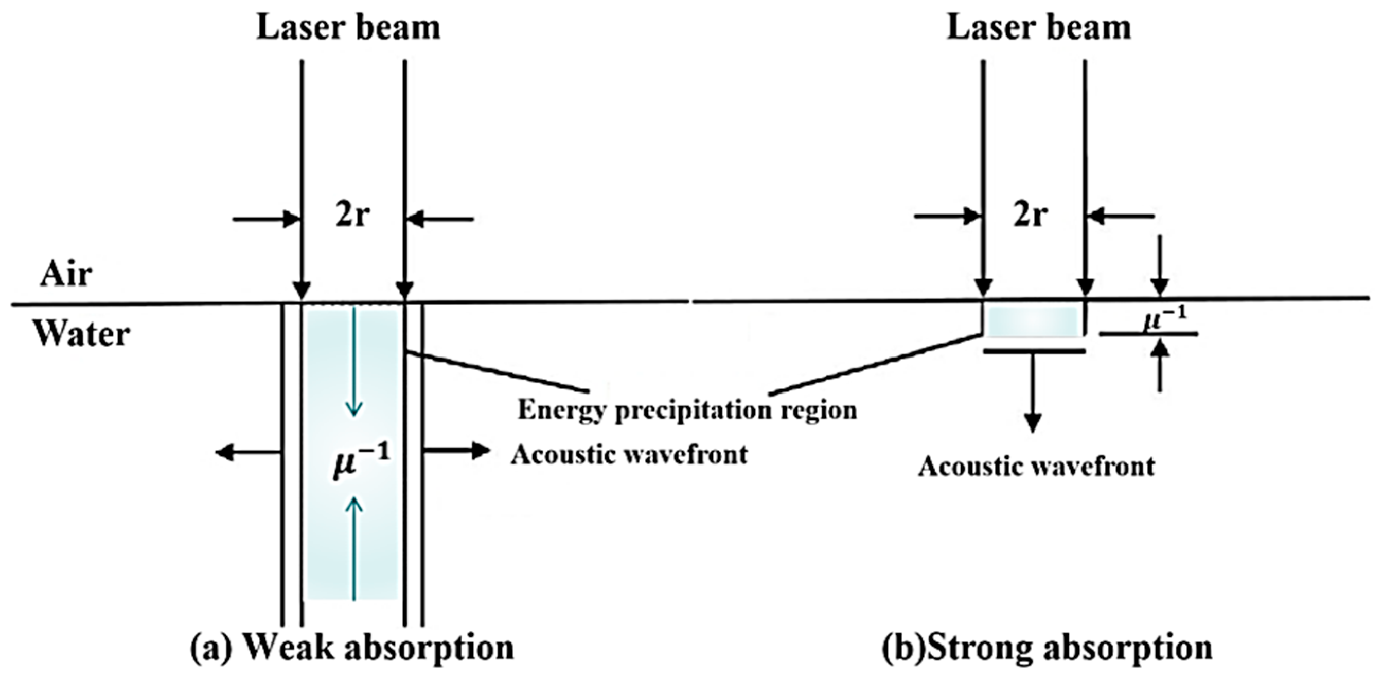
Assuming a laser beam with a characteristic radius r and an absorption coefficient μ for water, the optical extinction depth μ 1 is defined as the distance at which the laser energy attenuates to 1/e of its initial value. As illustrated in Figure 2, the shaded region represents the energy deposition zone within the liquid medium, which can be classified into two regimes: strong absorption and weak absorption. When r μ < < 1 the condition corresponds to weak absorption; conversely, r μ > > 1 represents strong absorption. In water, laser wavelengths with high absorption coefficients, combined with large beam divergence angles, are favorable for generating stronger LIA signals. On the other hand, if the laser wavelength falls outside the absorption band, the beam can propagate longer distances through water with minimal attenuation [64].
Table 2 summarizes the relationship between the optical extinction length in water and commonly used laser wavelengths, where λ denotes the laser wavelength and μ represents the absorption coefficient. The extinction lengths corresponding to CO2 and Nd:YAG lasers differ significantly, as water exhibits much stronger absorption at the CO2 laser wavelength compared to that of the Nd:YAG laser. Therefore, laser sources with appropriate wavelengths can be selected according to specific experimental objectives [65].

2.2. Phase-Change Vaporization Mechanism

In the photoacoustic energy conversion process within liquid media, vaporization-induced recoil effects can generate mechanical forces, thereby producing characteristic acoustic pulse signals. The laser energy density threshold required for vaporization-induced acoustic generation is approximately 2.3 J/cm3 [66]. Two typical vaporization modes are generally observed: A steady-state surface vaporization process occurring at the gas–liquid interface, and a transient explosive boiling process occurring in the subsurface region. The transition between these dominant modes is primarily governed by thermophysical parameters of the liquid, such as specific heat capacity and latent heat of vaporization. The photoacoustic conversion efficiency of vaporization processes can reach up to 1%, with the transient explosive boiling mode exhibiting superior acoustic generation efficiency compared to the steady-state surface vaporization mode [67,68].
Fletcher Blackmon et al. performed experiments under laboratory freshwater conditions using a pulsed laser with a 1 kHz repetition rate. In addition to inducing surface vaporization of the water medium, the results revealed the possibility of nonlinear interaction mechanisms. This nonlinear effect originates from the expansion and collapse of cavitation bubbles within the laser focal volume, giving rise to explosive boiling phenomena. The experiments demonstrated that the underwater sound pressure level (SPL) could reach up to 185 dB, and, for the first time, introduced the concept of nonlinear photoacoustic conversion [5].

2.3. Laser-Induced Optical Breakdown Mechanism

When the laser energy density exceeds the optical breakdown threshold of the liquid (107 W/cm2) [69], plasma is generated within the medium. This plasma continues to absorb optical energy, triggering an explosive expansion that produces outward-propagating shock waves. Approximately 65–85% of the shock wave energy is dissipated in water and eventually attenuates into acoustic waves. Compared to thermoelastic and vaporization mechanisms, the optical breakdown mechanism offers significantly higher photoacoustic conversion efficiency, ranging from 7 to 30% and thus serves as the dominant mechanism for high-power pulsed LIA generation. Table 3 presents the reported thresholds for optical breakdown.
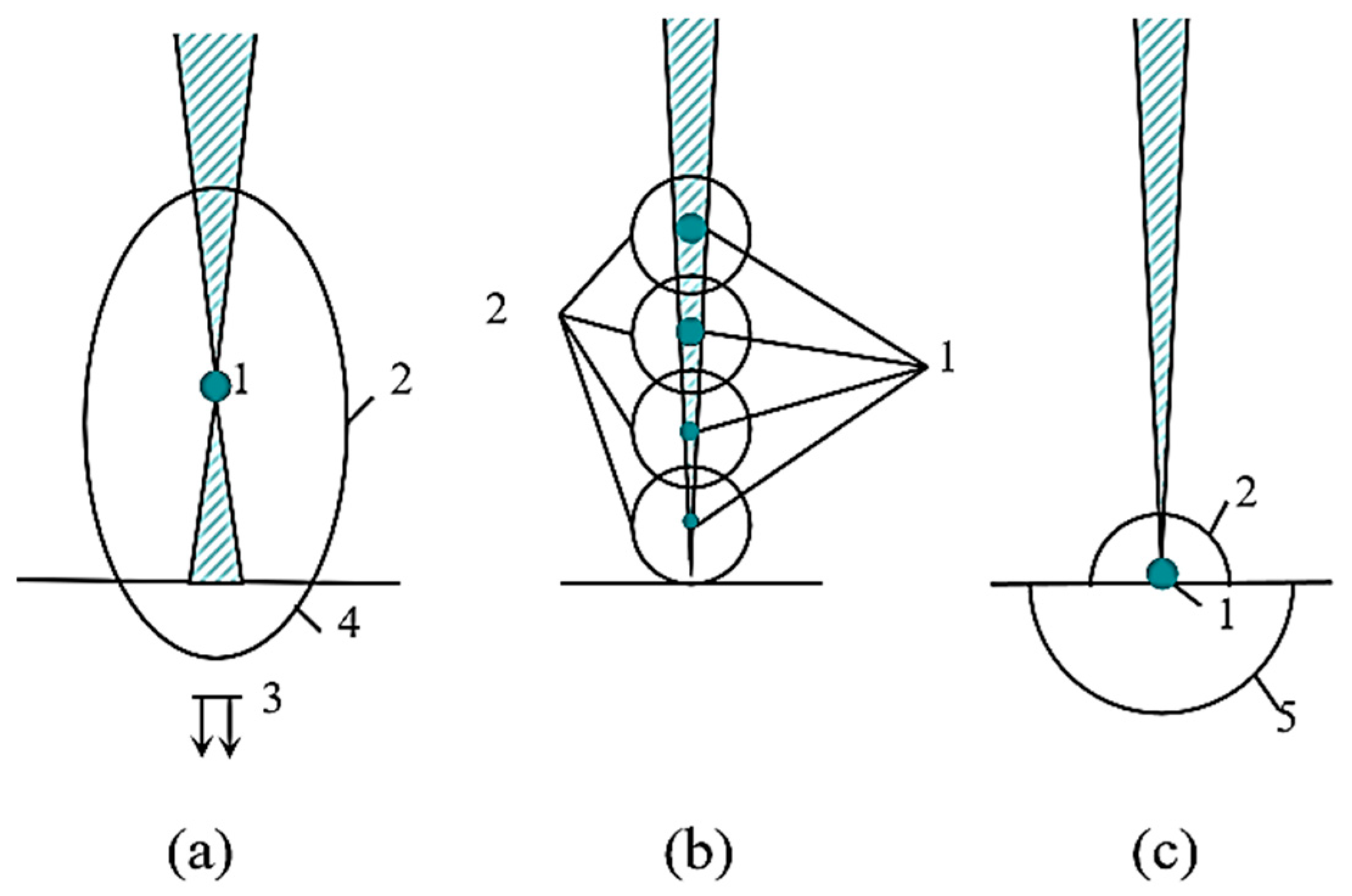
In cross-medium LIA processes, the spatial distribution of the optical breakdown threshold is influenced by multiple factors, including laser focal spot size, aerosol concentration, and beam incidence angle. These factors lead to spatial variability in the breakdown location. For example, using a CO2 laser with a wavelength of 10.6 µm and a focal spot diameter of 0.3 mm, three typical optical breakdown modes at the air–water interface have been experimentally observed. When a high-energy laser beam (15 J/cm2) is incident, optical breakdown occurs preferentially in the air region above the interface, as illustrated in Figure 3a. Due to plasma shielding effects, the trailing edge of the laser pulse is truncated, resulting in the generation of bipolar acoustic pulses with thermoelastic characteristics and peak pressures on the order of megapascals. The accompanying air shock wave, upon crossing the air–liquid interface, experiences a pressure amplitude jump caused by the abrupt acoustic impedance mismatch between the two media. This phenomenon follows the shock wave transmission behavior described by the Rankine–Hugoniot equations. Under low-divergence laser irradiation, a multi-focal breakdown structure is formed near the interface, as shown in Figure 3b. The shock waves generated by independently evolving plasma clusters exhibit nonlinear superposition during propagation, leading to a complex transient pressure field distribution. When the energy density decreases to approximately 10–15 J/cm2, optical breakdown occurs only at the surface layer of the water, as illustrated in Figure 3c. At this stage, a prominent surface flash is observed, accompanied by the simultaneous generation of shock waves in both the air and liquid phases. Notably, in laser acoustic remote sensing for underwater detection, the air shock wave and the acoustic pulse in water jointly form a composite acoustic source. The coupling characteristics of their propagation play a critical role in determining the detection sensitivity [69].
The dynamic behavior of cavitation bubbles and their acoustic radiation characteristics constitute an important research direction in LIAs. The generation and collapse of cavitation bubbles can induce high-intensity acoustic pulses, with their dynamics strongly influenced by boundary conditions and medium properties. In 2004, Chen, X. et al. [71] conducted foundational theoretical and experimental studies on bubble dynamics, characterizing bubble wall expansion, maximum and minimum diameters, and mechanical shock features during late-stage collapse. In 2007, Zhao, R. et al. [72] improved the experimental system to investigate the influencing factors of bubble generation and collapse and analyzed the acoustic signatures of cavitation near solid boundaries. In 2010, Zong, S. et al. [73] focused on cavitation erosion effects triggered by near-wall bubble collapse. In complex media, Li, S. et al. [74] in 2012 found that the dissolved gas content in liquids significantly modulates the frequency spectrum of cavitation-induced acoustic signals. Subsequent studies [75] revealed that double-bubble systems produce higher acoustic pressure amplitudes than single-bubble systems, while maintaining similar dominant frequency characteristics. In 2015, Li. further demonstrated through controlled pressure field experiments that pressure gradients can induce asymmetric bubble collapse, resulting in characteristic waveform distortions in the emitted acoustic pulses [76]. These findings provide a theoretical foundation for optimizing underwater acoustic sources and mitigating cavitation-induced damage.

2.4. Cross-Medium Propagation Characteristics of LIA Waves

In the atmosphere, laser propagation is influenced by the composition of the air. Table 4 lists the major atmospheric components, with those of higher concentration having a greater impact on laser transmission. A large number of gas molecules and aerosol particles of various sizes in the air cause scattering of the laser beam, primarily through Rayleigh scattering and Mie scattering mechanisms [64]. These scattering processes lead to attenuation of the laser beam during propagation. The extent of scattering depends on the laser wavelength, particle size distribution, and the concentration of atmospheric constituents. These factors collectively affect the transmission efficiency of laser systems under different atmospheric conditions.
Secondly, the directivity of the acoustic source has a notable influence on the SPL. Let r denote the distance from the measurement point to the acoustic source, and θ represent the angle between the normal direction of the acoustic source and the line connecting the source to the detector. K = ω/c1 denotes the wavenumber, where c1 is the speed of sound in water, and A is the amplitude constant of the acoustic wave with angular frequency. The acoustic pressure with an angular frequency ω at a propagation distance r, generated by the laser-induced acoustic wave in water, can be expressed as
p = A cos θ r e i ( k r - ω t )
Due to the expansion of the acoustic wavefront, its effect on the SPL can be described by Equation (2):
L t w = 20 lg r 20 lg ( cos θ )
Based on the quantitative relationship between acoustic source directivity and SPL, the acoustic field distribution can be divided into two characteristic regions. For angles θ < 50°, the SPL exhibits low sensitivity to the radiation direction, which is primarily attributed to the coherent superposition effect along the axial acoustic field. In contrast, for θ 50°, the SPL shows significant directional dependence, mainly due to the coupling between edge diffraction effects and acoustic wave interference [69].
In atmospheric channels, the wavelength of 1.06 µm is a typical “atmospheric window,” characterized by high transmittance and low propagation attenuation. In practical LIA experiments, most of the laser energy at this wavelength can be effectively utilized. Under low-visibility conditions, the laser is capable of maintaining short-range propagation, whereas under high-visibility conditions, it exhibits significantly higher transmittance [64].
When a laser crosses the air–water interface, energy loss occurs due to reflection at the boundary, and the corresponding loss in SPL is dependent on the laser incidence angle at the water surface. The acoustic energy loss across the air–water interface exhibits a nonlinear increase with the incident angle. For incidence angles between 0° and 80°, the interface-induced loss remains below 45 dB and increases gradually. However, when the incidence angle exceeds 80°, the loss rises exponentially, reaching values as high as 110 dB. Even under normal incidence, each laser crossing of the interface results in a SPL loss of approximately 65 dB [69].
The acoustic waves generated by laser incidence propagate in water through energy transfer mechanisms that rely on vibrational coupling between adjacent water molecules. During propagation, part of the acoustic energy is gradually converted into thermal energy, leading to attenuation of the acoustic signal. This energy loss is primarily attributed to viscous absorption and molecular relaxation processes. W.H. Thorp provided an empirical formula for calculating the acoustic attenuation coefficient in seawater. This formula is applicable only to acoustic waves with frequencies greater than 5 kHz [77]:
α 3 × 10 4 f 2 + 44 f 2 4100 + f 2 + 0.11 f 2 1 + f 2
In the equation, α denotes the acoustic attenuation coefficient in seawater (dB/km), and f represents the acoustic frequency (kHz). f 2 represents viscous absorption in water; 44f2/4100 + f2 represents relaxation absorption due to borate ions; 0.11f2/(1 + f2) represents relaxation effects caused by magnesium sulfate ions below 100 kHz. The acoustic attenuation coefficients in freshwater and seawater vary with frequency, and at the same acoustic frequency, the attenuation in seawater is consistently higher than that in freshwater. In freshwater, the absorption coefficient increases approximately linearly with rising acoustic frequency, whereas in seawater, the increase follows a nonlinear trend [64]. This indicates that the low-frequency components of LIA signals experience less attenuation in water, particularly in cross-air–water propagation scenarios, making the low-frequency band more favorable for underwater information transmission.
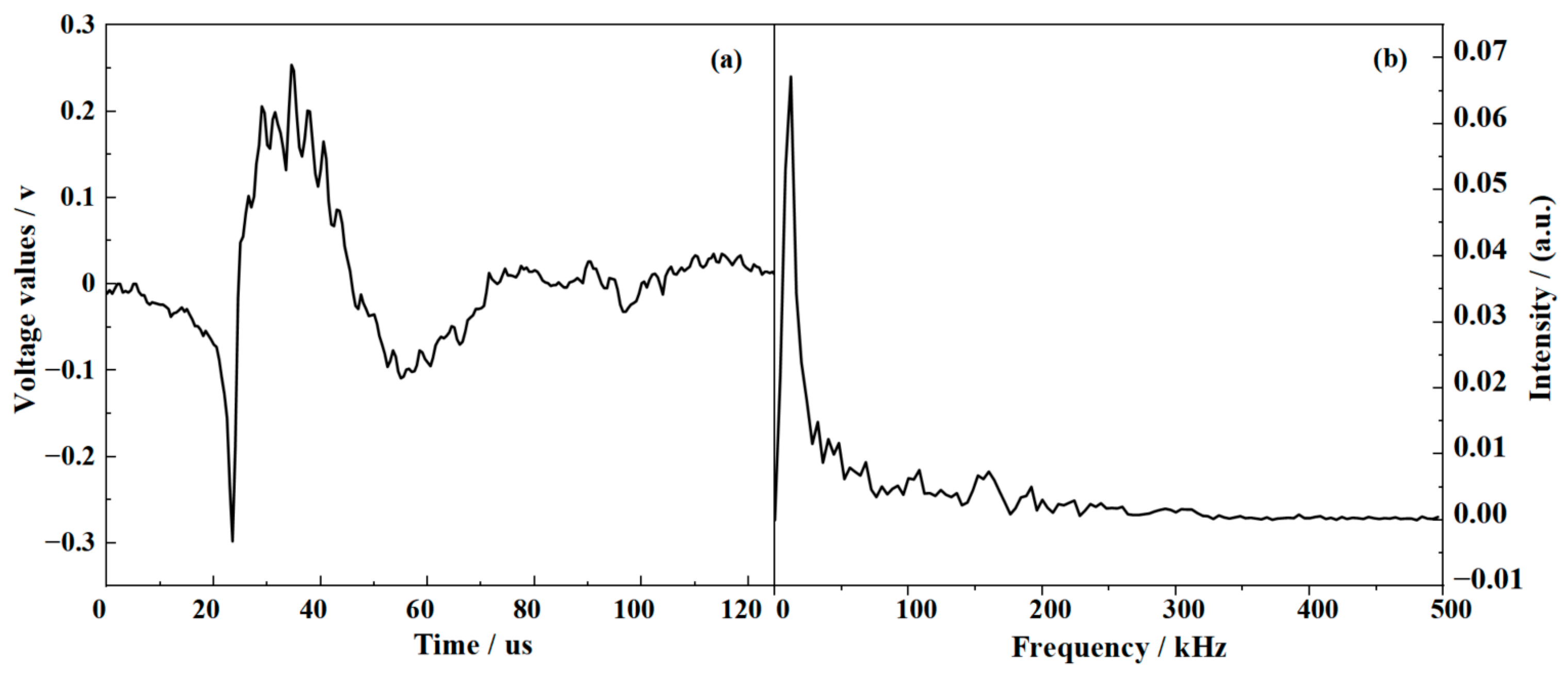
The time–frequency and propagation characteristics of typical laser-induced acoustic signals were analyzed by our team. A laser system with a wavelength of 1064 nm, a pulse repetition rate of 1–10 Hz, a pulse width of 6–8 ns, and a single-pulse energy of 260 mJ was employed. The time-frequency characteristics of the acoustic signal generated at a depth of 20 cm below the lake surface are presented in Figure 4. The laser-induced acoustic waveform exhibits a characteristic bipolar profile with a pulse duration of approximately 125 µs and a frequency range spanning 0–500 kHz. The signal energy is primarily distributed within the 0–50 kHz band, with a dominant peak at 24 kHz. The variations in SPL and signal-to-noise ratio (SNR) with depth were investigated. Both SPL and SNR decrease progressively with increasing depth, and a nonlinear fitting yielded an excellent correlation (R2 = 0.99968), indicating that the model provides an accurate representation of the observed trend. This finding is consistent with the theoretical framework of acoustic wave propagation in stratified media, suggesting that depth induces a nonlinear attenuation effect on the acoustic signal. The result provides a theoretical basis for evaluating SPL behavior at varying depths [37].

3. Influence of Laser Parameters on Acoustic Signal Characteristics

3.1. Selection of Laser Wavelength

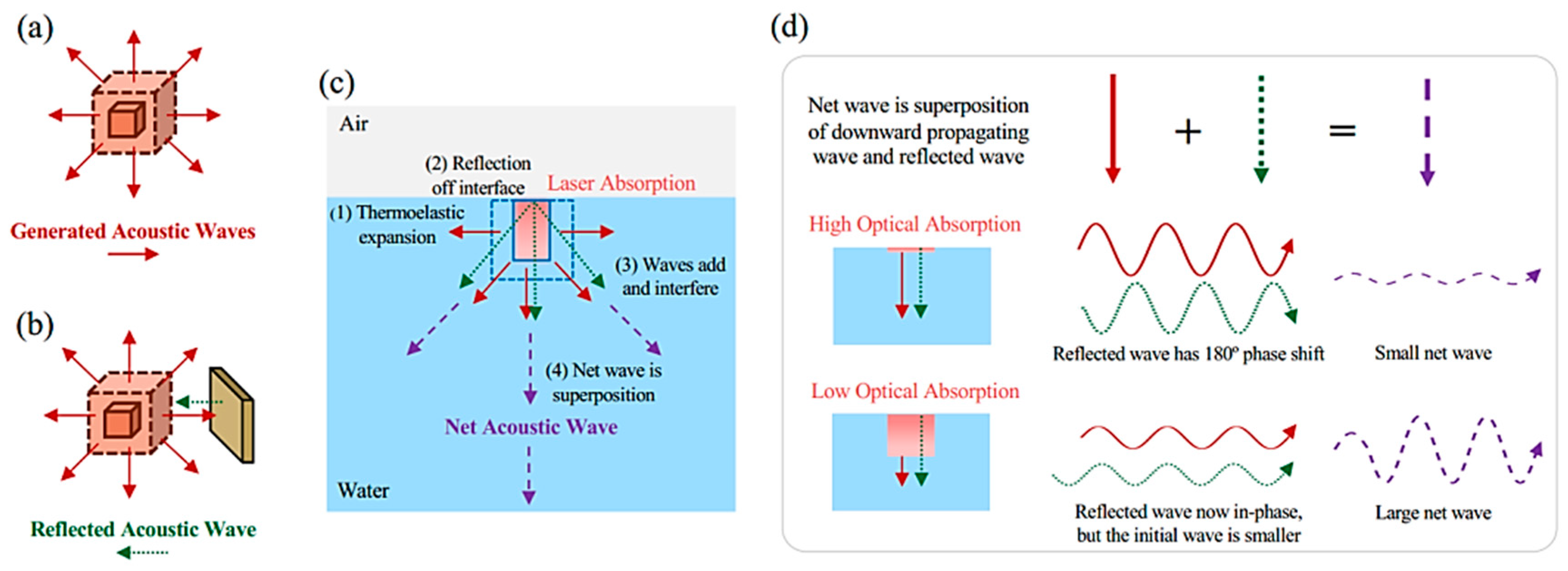
In underwater acoustic detection systems, impedance mismatches at medium interfaces can induce complex wave field coupling phenomena. As illustrated in Figure 5, the abrupt mechanical property transition at the air–water interface causes significant reflection of incident acoustic waves. These reflected waves vectorially superimpose with the direct acoustic waves generated by the laser source, and the resulting interference pattern is influenced by the selected laser wavelength.
When a laser with a strongly absorbing wavelength is used, the reflected wave tends to destructively interfere with the original downward-propagating wave, leading to a pronounced cancellation effect. Conversely, for weakly absorbing wavelengths, the reflected wave can remain in phase with the downward acoustic wave, resulting in constructive interference and an enhanced net acoustic pressure field [78,79]. However, weakly absorbing wavelengths exhibit lower optical-to-acoustic energy conversion efficiency, which limits the amplitude of the initial acoustic signal [41].
To achieve effective excitation of high-amplitude acoustic waves underwater, it is essential to systematically consider the coupling mechanisms between laser parameters and medium properties. In the process of selecting the laser wavelength, three key factors must be jointly optimized: destructive interference effects, photoacoustic conversion efficiency, and compatibility with commercially available laser sources. The extinction lengths of CO2 and Nd:YAG lasers in water differ by several orders of magnitude, which directly reflects the fact that water molecules exhibit absorption coefficients in the mid-infrared range that are approximately three orders of magnitude higher than those in the near-infrared range. Based on the aforementioned differences in extinction characteristics, engineering applications must optimize laser parameters according to specific operational scenarios. For near-field acoustic pressure enhancement, strongly absorbing CO2 lasers are preferred due to their high transient thermal deposition efficiency. In contrast, for long-range acoustic propagation, Nd:YAG lasers are more suitable owing to their lower attenuation in the medium, which helps maintain acoustic intensity over extended distances. This wavelength selection strategy enables effective control over spatial energy deposition during laser–fluid interactions, thereby optimizing the spatiotemporal evolution of the underwater acoustic field.

3.2. Influence of Laser Pulse Duration and Single-Pulse Energy

Laser pulse duration and single-pulse energy are decisive factors in determining laser intensity and are also critical to the effectiveness of cross-medium acoustic generation. As shown in Table 5, ns lasers generally exhibit higher energy conversion efficiency than picosecond (ps) pulsed lasers. With increasing incident laser energy, the energy conversion efficiency of ns pulses tends to decrease, whereas that of ps pulses remains relatively stable. In terms of photoacoustic energy conversion performance, ns laser outperforms ps laser [49].
The quantitative mapping model between the acoustic signal characteristics and the laser energy parameters is systematically analyzed. With increasing input laser energy, the energy deposition and photon absorption efficiency are enhanced, leading to a prolonged acoustic pulse duration. Simultaneously, the peak-to-peak overpressure of the direct, reflected, and transmitted signals increases, while the arrival times of the reflected and transmitted signals are shortened. The acoustic pulse energy exhibits a linear increase with rising laser input energy, and the energy conversion efficiencies of both reflected and transmitted waves at the air–water interface also increase approximately linearly. In addition, the peak frequencies of the direct and reflected signals shift toward lower frequencies, which is attributed to the extended duration of optical radiation and thermal emission effects. The low-frequency components of the signals experience less attenuation in air and can propagate over longer distances. Furthermore, the spectral bandwidths of the direct and reflected signals are reduced, whereas the bandwidth of the transmitted signal remains unchanged [49].

4. LIA Detection Systems

In 1981, the Hickman team developed a modular laser–acoustic underwater detection system [44]. The system consists of four core modules: A Lumonics TEA-103-2 small-aperture CO2 laser capable of delivering adjustable pulse energies ranging from 1 to 15 J at a wavelength of 10.6 µm; an acoustic receiving array based on a parabolic reflector; a multi-channel signal acquisition and analysis unit; and a mobile deployment platform. Laboratory calibration and field testing confirmed the system’s adaptability across multiple application scenarios. It has been successfully employed in shallow and turbid water depth sounding, underwater target detection, and soil moisture measurement. Since the system is not hardwired to any specific transmitter or sensor, it can also be adapted for navigation and communication purposes.
In 2016, the Bidin team developed a Laser-Induced Acoustic spectroscopy (LIAS) based system for detecting waterborne pollutants [46]. The pulsed excitation module employs a Q-switched Nd:YAG laser with a wavelength of 1064 nm and a pulse energy of 40 mJ to induce laser breakdown in the solution. The optical detection module includes a wavelength-tunable dye laser used as the light source for schlieren imaging. The synchronization control module utilizes a photodiode to monitor the laser pulse in real time, with timing coordination achieved via a delay generator. The high-speed imaging module incorporates a CCD camera to capture the dynamics of acoustic wave propagation. Experimental results revealed a correlation between the acoustic characteristics of LIA in water and the concentration of hydrocarbons. Specifically, the propagation velocity of the acoustic signal was found to be proportional to the hydrocarbon concentration, and the signal amplitude increased linearly with rising hydrocarbon levels. It has been confirmed that LIAS technology offers significant advantages for real-time, in situ monitoring, turbid-water detection, and pollution source localization. These findings provide crucial technical support for the development of next-generation water environment monitoring systems.
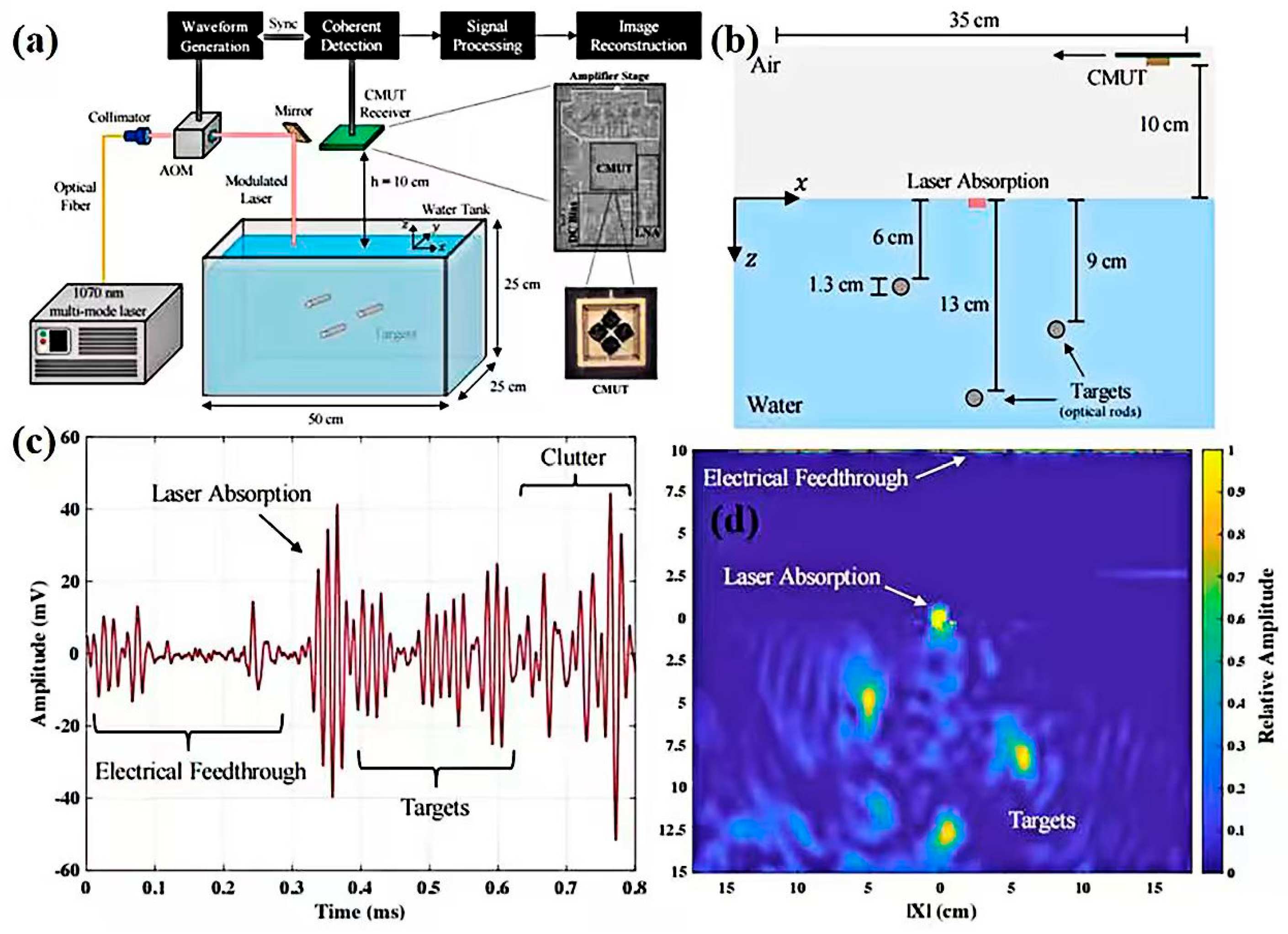
In 2020, the Fitzpatrick research team developed an airborne acoustic imaging system based on CMUT [41]. Its innovative architecture is illustrated in Figure 6. A key distinguishing feature of this system lies in its use of air-coupled CMUT, which addresses the issues of acoustic impedance mismatch and transmission loss associated with airborne echoes [80,81,82]. Additionally, due to the limited bandwidth of CMUT, a sufficient number of oscillation cycles at the resonant frequency is required to achieve the high sensitivity that sets them apart from other non-contact sensing devices [83].
As illustrated in Figure 7a, the imaging mechanism of this system involves three key physical processes: LIA waves propagate through the underwater medium and are reflected by the target; the reflected acoustic waves cross the air–water interface, with a phase compensation layer enhancing transmission; the CMUT array receives the acoustic signals on the air side, and time–frequency analysis is used to reconstruct the target [84]. Theoretical modeling indicates that conventional 10.6 µm lasers suffer from destructive interference caused by surface reflections, leading to a SPL attenuation of up to 46 dB. To address this, the system employs an optimized multi-peak laser source with a wavelength of 1070 nm, a peak power of 500 W, and a pulse width of 20 ns, resulting in a significant improvement in acoustic energy transmission efficiency. The experimental setup is shown in Figure 7b. Imaging tests were conducted on standard targets placed at water depths of 6 cm, 9 cm, and 13 cm, with a detection height of 10 cm. The corresponding acoustic feature analysis is presented in Figure 7c. While the test height was set to 10 cm, it can be proportionally scaled up in real-world system demonstrations, with operational altitudes reaching several meters. Figure 7d shows the laser–acoustic imaging result obtained using this system. The feasibility of airborne laser–acoustic remote sensing imaging has been demonstrated.
In 2021, the Yellaiah team established an integrated experimental-simulation platform to investigate the acoustic coupling characteristics at the water–air interface [40]. Based on experimental observations, finite element analysis was performed to successfully visualize the propagation and interaction of underwater acoustic pulses at the interface. The analysis revealed that shock waves attenuate in the forward direction during propagation and transform into acoustic pulses, whose signal characteristics can be used to characterize both the shock wave propagation behavior and interface interactions. The experiments employed a Nd:YAG laser with a wavelength of 532 nm, a pulse duration of 10 ns, and an energy range of 40–100 mJ. Underwater acoustic signals generated via LIB were captured using a needle-type hydrophone, while a polarized microphone placed above the water surface was used to record the transmitted and reflected acoustic signals in air. The attenuation and frequency shift in acoustic waves during propagation from water into air were analyzed, providing important insights into acoustic interactions across different media.
In 2008, Zong, S. et al. conducted a systematic study on the acoustic radiation mechanisms of laser-induced cavitation dynamics [85]. The experiments employed a Q-switched Nd:YAG laser with a wavelength of 1064 nm, a pulse duration of 8 ns, and an adjustable energy range of 100–800 mJ. Particular emphasis was placed on evaluating the acoustic characteristics under single-pulse energy of 500 mJ and a repetition rate of 5 Hz. The hydrophone was positioned 80 mm from the optical breakdown point, and the expansion and collapse phases of the cavitation bubble were analyzed based on the peak position and amplitude of the received acoustic signals. Experimental results showed that, under the optical breakdown regime, the acoustic signal generated during bubble collapse exhibited higher intensity than that generated during bubble expansion [86,87]. When the hydrophone was placed 1 m from the breakdown point, the acoustic signal reached a SPL of 200.6 dB, meeting the requirements for underwater detection [88]. It was found that the SPL of the underwater acoustic signal increased proportionally with the incident laser energy. However, when the laser energy reached 500 mJ, the SPL exhibited nonlinear behavior.
In 2009, Zhao, A. et al. made a breakthrough by developing a full-condition laser–acoustic detection system [89]. Under non-anechoic water tank conditions, the acoustic waves received by the array elements of the system’s base array were concentrated within a conical region with a half-apex angle of approximately 130°. To effectively capture the acoustic signals, the array needed to be positioned at a considerable distance from the laser–water interaction point. Given that the speed of sound in water is significantly higher than that in air, this configuration allows for effective temporal and spatial separation between the LIA echoes and ambient noise, thereby improving signal-to-noise discrimination.
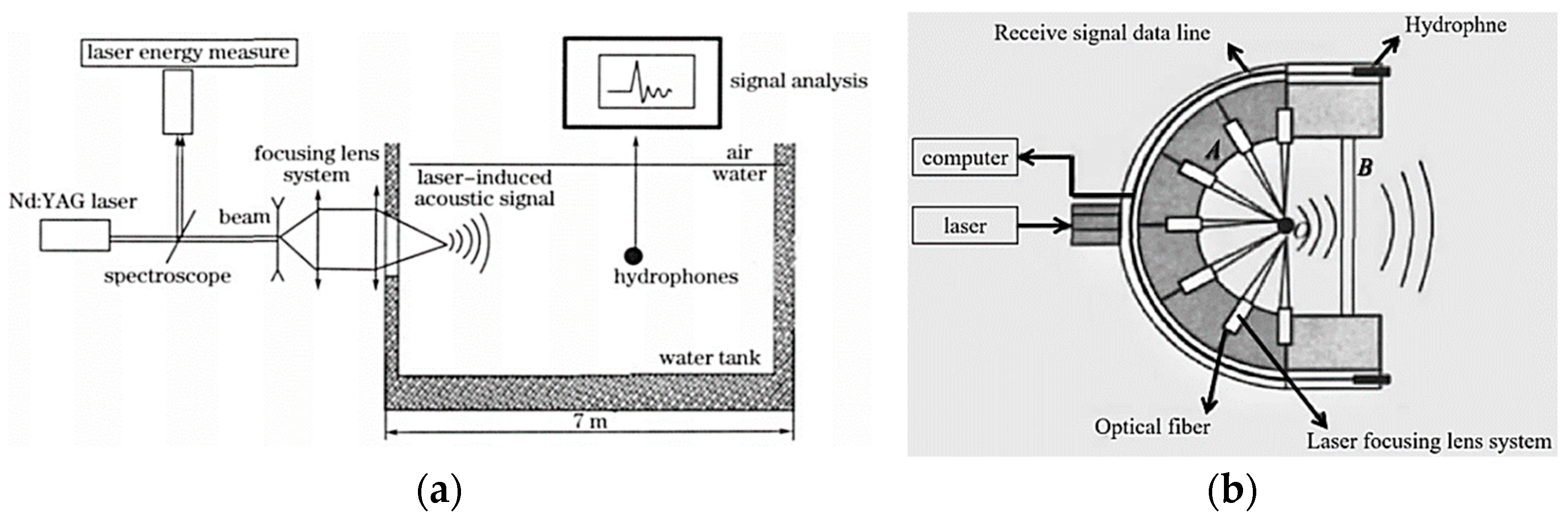
In 2010, Zong, S. et al. designed a laser–acoustic radiation measurement system [90], with its core innovation being the construction of a quasi-free-field testing environment. By installing ATF-1 sulfur-free rubber sound-absorbing materials on the walls, bottom, and surface of the water tank, the setup effectively simulated free-field acoustic propagation conditions similar to those in the ocean. This configuration enabled accurate measurement of both the direct acoustic wave generated by the laser and the echo signals reflected from underwater targets. Experimental results showed that the LIA signal had a peak pressure pulse width of 15 µs, with dominant frequencies at 15 kHz, 69 kHz, 166 kHz, and 365 kHz. The research team derived a far-field acoustic radiation model for laser-induced sound, as shown in Equations (4) and (5). Assuming the cavitation bubble is spherical, r represents the radius of the plasma cavity, t is time, and p(r,t) denotes the sound pressure at position r and time t. |A|/r is the pressure amplitude, k = ω /c is the acoustic wave number, and u 0 is the vibration amplitude at the surface of the spherical source. It can be seen that the sound pressure amplitude depends not only on the vibration amplitude of the spherical source but also on the radius of the cavitation bubble.
p ( r , t ) = A r exp [ j ( ω t k r + θ ) ]
A = ρ 0 c 0 k r 0 u 0 1 + ( k r 0 ) 2
In 2012, Liu, T. et al. developed a laser–acoustic directional detection system based on wavefront reconstruction [91], with its innovative architecture illustrated in Figure 8b Experimental results demonstrated that a strong pulsed laser focused into a liquid medium can generate an explosive spherical acoustic source, and the detector is capable of converting the spherical acoustic wave into a highly directional plane wave signal. In the system, wall A guides the laser pulse through a beam-expansion and focusing module, focusing it onto point O. Simultaneously, multiple laser pulses delivered via optical fibers are also focused at point O, where they induce acoustic waves through water surface breakdown. These acoustic waves are reflected by the acoustic reflector wall A and emitted into the water through the acoustic vibration surface B. Upon encountering a target, the reflected acoustic echoes are received by a hydrophone and processed by a signal processing unit to complete the underwater detection task.
In 2015, Ye, J. et al. proposed a method for underwater target estimation using LIAs. By measuring the echo signal attenuation of different materials and calculating the frequency spacing between extrema in the reflected comb-like spectrum, the target size can be estimated [92]. Under the boundary conditions of continuity of normal particle velocity and acoustic pressure at the two interfaces in front of and behind the target, the reflection coefficient R for underwater acoustic-solid coupling is given by
R = Z 2 ( Z 3 Z 1 ) cos ( k 2 L cos θ ) + j ( Z 2 2 Z 1 Z 3 ) sin ( k 2 L cos θ ) Z 2 ( Z 3 + Z 1 ) cos ( k 2 L cos θ ) + j ( Z 2 2 + Z 1 Z 3 ) sin ( k 2 L cos θ )
Z 1 is the acoustic impedance of the water medium, and Z 1   =   Z 3 is the acoustic impedance of the underwater target material, L denotes the thickness of the reflecting medium, θ is the incident angle of the acoustic signal, and k 2 = f / c is the acoustic wave number in the target material. It can be seen that the reflection coefficient R is a function of frequency. By taking the logarithm of the reflection coefficient and analyzing the frequency spacing between adjacent extrema in the comb-like spectrum of log(R), the thickness d of the reflecting medium can be estimated.
d = 2 π c Δ f
Here, c represents the speed of sound in water for the LIA signal, and f is the frequency spacing between adjacent extrema in the comb-like spectrum. Using this method, the size of the underwater target can be effectively estimated [92].
In 2022, Zhao, Y. et al. applied the LIA Synthetic Aperture Focusing Technique (SAFT) to enhance target detection. By constructing a laser source array to concentrate optical energy, the system achieved focused and intensified acoustic energy delivery to underwater targets, thereby improving lateral resolution and overall imaging accuracy [93]. Finite element simulations were conducted to analyze the impact of surface water disturbances on LIA signals, as illustrated in Figure 9a–d. The results show that surface perturbations significantly affect the signal: greater disturbance amplitudes lead to lower acoustic signal amplitudes and reduced signal-to-noise ratios (SNR). Figure 9e compares acoustic signals under different laser focusing configurations. The detection effectiveness of a central-focusing eight-source laser array was approximately 3.46 times greater than that of a single-source array, demonstrating that integrating LIAs with SAFT is beneficial for improving underwater target detection performance.

5. Discussion

As an emerging approach for underwater detection, LIA technology still encounters several critical technical challenges in practical applications. The primary difficulties involve achieving efficient conversion of laser energy into acoustic energy, maintaining long-range propagation of acoustic waves in underwater environments, and enhancing the anti-interference capability of optical focusing systems under real sea-surface wave conditions [94,95].
Currently, the energy conversion efficiency of LIA technology is constrained by seawater absorption and scattering, as well as by laser parameters such as wavelength and pulse width. Future efforts should focus on optimizing laser wavelength selection, pulse energy, and focusing strategies to enhance laser-to-acoustic conversion efficiency. Report the conversion efficiency from energy to SPL and SNR under specified turbidity and dissolved-gas conditions, including laser fluence, focal spot, laser-to-acoustic efficiency bandwidth, and the stability of peak sound pressure. Explore pulse-train shaping to raise thermoelastic yield without damaging breakdown. Regarding underwater acoustic propagation, viscous absorption, molecular relaxation, and scattering significantly degrade signal strength and fidelity [96]. To extend detection range and improve resolution, advanced compensation algorithms for acoustic attenuation are required. Moreover, multi-frequency signal fusion techniques hold considerable potential for suppressing ambient noise and improving the SNR. Given the inherently weak acoustic signals generated by LIA, high-sensitivity acoustic sensors are indispensable [97]. Among them, fiber-optic hydrophones and piezoelectric composite sensors have emerged as key research directions owing to their high sensitivity and strong anti-interference capabilities [98]. Future development should aim to broaden their frequency response and expand their dynamic range to better adapt to complex underwater environments. Additionally, integrating LIA systems with optical imaging and magnetic sensing promises to enable the development of multimodal detection platforms. Leveraging deep learning algorithms to fuse and interpret multi-source data can further enhance target recognition accuracy and improve environmental perception. Finally, breakthroughs in real-time data processing and transmission will be critical for achieving the operational viability of LIA-based underwater sensing systems.

6. Conclusions

With the miniaturization of lasers, acoustic sensors, and signal processing modules, LIA systems are expected to evolve toward portable and highly integrated configurations, enabling deployment on autonomous underwater vehicles and unmanned platforms. By optimizing laser parameters and acoustic signal processing algorithms, future LIA technologies are poised to achieve higher spatial resolution and longer-range underwater target detection, providing strong support for ocean resource exploration and military applications. To address the challenges posed by turbid waters, high-pressure deep-sea environments, and other complex marine conditions, the development of real-time environmental calibration techniques and highly stable LIA systems with enhanced adaptability becomes a critical priority. Coupled with interface-aware focusing, uncertainty-calibrated multimodal fusion, and rigorous safety/compliance reporting, these measurable milestones provide a practical path to transition LIA from promise to practice in complex marine environments. In summary, LIA technology demonstrates broad application prospects in underwater sensing. With continuous breakthroughs in key enabling technologies, LIA systems are expected to play a pivotal role in defense, marine environmental monitoring, and disaster early-warning systems.

Author Contributions

Conceptualization, J.Z. and M.W.; methodology, Y.Y. and K.Y.; validation, D.X., J.Y. and S.X.; formal analysis, J.Z. and S.X.; investigation, J.Z.; resources, D.X., J.Y. and M.W.; writing—original draft preparation, J.Z. and M.W.; writing—review and editing, Y.Y. and K.Y.; project administration, X.W.; funding acquisition, J.Y. and D.X. All authors have read and agreed to the published version of the manuscript.

Funding

This research was funded by the National Natural Science Foundation of China (Nos.12174211, 11874232, 12174212) and the Laoshan Laboratory Science and Technology Innovation Project, grant number No. LSKJ202200801. We give our thanks for the support of the Qingchuang team.

Data Availability Statement

The original contributions presented in this study are included in the article. Further inquiries can be directed to the corresponding authors.

Conflicts of Interest

The authors declare no conflicts of interest. The funders had no role in the design of the study; in the collection, analyses, or interpretation of data; in the writing of the manuscript; or in the decision to publish the results.

References

  1. Aussel, J.D.; Le Brun, A.; Baboux, J.C. Generating acoustic waves by laser: Theoretical and experimental study of the emission source. Ultrasonics 1988, 26, 245–255. [Google Scholar] [CrossRef]
  2. Kaushal, H.; Kaddoum, G. Underwater Optical Wireless Communication. IEEE Access 2016, 4, 1518–1547. [Google Scholar] [CrossRef]
  3. Zemlyanov, A.A.; Alexander, A.; Bochkarev, N.N.; Nikolay, N.; Kabanov, A.M.; Andrey, M.; Pogodaev, V.A.; Vitalii, A. Generation of acoustic pulses on the natural centers of absorption with propagation CO2 laser radiation on atmospheric paths. Proc. SPIE Int. Soc. Opt. Eng. 2001, 4341, 202–209. [Google Scholar]
  4. Anisimov, S.I. Vaporization Of Metal Absorbing Laser Radiation. In 30 Years of the Landau Institute—Selected Papers; World Scientific Series in 20th Century Physics; World Scientific: Singapore, 1996; pp. 14–15. [Google Scholar]
  5. Antonelli, L.; Blackmon, F. Experimental demonstration of remote, passive acousto-optic sensing. J. Acoust. Soc. Am. 2004, 116, 3393–3403. [Google Scholar] [CrossRef]
  6. Ma, Y.L.; Yang, Y.X.; He, Z.Y.; Yang, K.D.; Sun, C.; Wang, Y.M. Theoretical and practical solutions for high-order superdirectivity of circular sensor arrays. IEEE Trans. Ind. Electron. 2013, 60, 203–209. [Google Scholar] [CrossRef]
  7. Yang, Y.X.; Zhou, J.B.; L, M.Y.; Hou, X.H.; Yang, L.; Xie, L.; Wang, L.; Shen, H.; Liu, X.H.; Lei, B.; et al. Underwater acoustics: Current status and future trends. Tech. Acoust. 2025, 44, 309–332. [Google Scholar]
  8. Du, Z.P.; Chen, G.; Wang, D. Foreign sonar technology development research summary. Ship Sci. Technol. 2019, 41, 145–151. [Google Scholar]
  9. Zhang, G.; Zhang, L.; Wang, Y.; Ma, Y.; Zhou, X.; Yu, Y. Spatiotemporal Analysis of Sonar Detection Range in Luzon Strait. J. Mar. Sci. Eng. 2024, 12, 1191. [Google Scholar] [CrossRef]
  10. Jia, Y.J.; Wang, P.B.; Wei, H.K.; Chen, Q.; Hu, Y.H. Research on high-resolution processing of frequency modulation combined signal for active sonar detection. Front. Phys. 2025, 13, 1542037. [Google Scholar] [CrossRef]
  11. Wang, X.; Zhang, Z.; Shang, X. Research on Improved YOLO11 for Detecting Small Targets in Sonar Images Based on Data Enhancement. Appl. Sci. 2025, 15, 6919. [Google Scholar] [CrossRef]
  12. Xie, L.; Sun, C.; Kong, D.Z. Matched-phase weighting beamformer to improve the gain of a long linear array in the range-dependent ocean waveguide. IEEE Access 2020, 8, 177437–177446. [Google Scholar] [CrossRef]
  13. Lu, J.Y.; Yang, Y.X.; Yang, L. An efficient off-grid direction-of-arrival estimation method based on inversefree sparse Bayesian learning. Appl. Acoust. 2023, 211, 109521. [Google Scholar] [CrossRef]
  14. Fillinger, L.; Hunter, A.J.; Zampolli, M.; Clarijs, M.C. Passive Acoustic Detection of Closed-Circuit Underwater Breathing Apparatus in an Operational Port Environment. J. Acoust. Soc. Am. 2012, 132, EL310–EL316. [Google Scholar] [CrossRef]
  15. Sun, Y.C.; Chen, W.Y.; Wang, P.B. Review of research on the characteristics of underwater acoustic signal of frogman. Tech. Acoust. 2022, 41, 479–488. [Google Scholar]
  16. Dong, L.; Li, N.; Xie, X.; Bao, C.; Li, X.; Li, D. A Fast Analysis Method for Blue-Green Laser Transmission through the Sea Surface. Sensors 2020, 20, 1758. [Google Scholar] [CrossRef] [PubMed]
  17. Collin, A.; Archambault, P.; Long, B. Mapping the Shallow Water Seabed Habitat with the SHOALS. IEEE Trans. Geosci. Remote Sens. 2008, 46, 2947–2955. [Google Scholar] [CrossRef]
  18. Tulldahl, H.M.; Philipson, P.; Kautsky, H.; Wikstrom, S.A. Sea Floor Classification with Satellite Data and Airborne Lidar Bathymetry. In Ocean Sensing and Monitoring V, Proceeding of the SPIE, the International Society for Optics and Photonics, Baltimore, MD, USA, 30 April–1 May 2013; Hou, W.W., Arnone, R.A., Eds.; SPIE-Int Soc Optical Engineering: Bellingham, WA, USA, 2013; Volume 8724, p. UNSP 87240B. ISBN 978-0-8194-9515-0. [Google Scholar]
  19. Li, X.; Miao, X.; Qi, X.; Han, X. Research on the propagation characteristics of blue-green laser through sea surface with foams. Optik 2018, 170, 265–271. [Google Scholar] [CrossRef]
  20. Birkebak, M.; Eren, F.; Pe’eri, S.; Weston, N. The Effect of Surface Waves on Airborne Lidar Bathymetry (ALB) Measurement Uncertainties. Remote Sens. 2018, 10, 453. [Google Scholar] [CrossRef]
  21. Ma, J.; Lu, T.; He, Y.; Jiang, Z.; Hou, C.; Li, K.; Liu, F.; Zhu, X.; Chen, W. Compact Dual-Wavelength Blue-Green Laser for Airborne Ocean Detection Lidar. Appl. Opt. 2020, 59, C87–C91. [Google Scholar] [CrossRef]
  22. Hostetler, C.A.; Behrenfeld, M.J.; Hu, Y.; Hair, J.W.; Schulien, J.A. Spaceborne Lidar in the Study of Marine Systems. Annu. Rev. Mar. Sci. 2018, 10, 121–147. [Google Scholar] [CrossRef]
  23. Wu, Z.; Li, H.; Yang, F.; Li, S.; Gao, J.; Zhang, W.; Jin, S.; Huo, G.; Shang, J.; Yang, K.; et al. High-Resolution Seafloor Topography and Morphology—Detection, Processing Theory and Techniques; Science Press: Beijing, China, 2017; ISBN 978-7-03-052904-6. [Google Scholar]
  24. Ng, R.; Sachat, A.; Cespedes, F.; Poblet, M.; Madiot, G.; Jaramillo-Fernandez, J.; Xiao, P.; Florez, O.; Sledzinska, M.; Sotomayor-Torres, C.; et al. Excitation and Detection of Acoustic Phonons in Nanoscale Systems. Nanoscale 2022, 14, 13428–13451. [Google Scholar] [CrossRef]
  25. Ikei, A.; Sampath, K. Remote Operation of a Single-Point LDV System to Acquire 2D Measurements. arXiv 2021, arXiv:2102.13031. [Google Scholar] [CrossRef]
  26. Jin, Y.; Dollevoet, R.; Li, Z. Removing Speckle Noise from the Signals of a Laser Doppler Vibrometer on Moving Platforms (LDVom) by Ensemble Empirical Mode Decomposition. Meas. Sci. Technol. 2022, 33, 125205. [Google Scholar] [CrossRef]
  27. Yuan, K.; Zhu, W.D. A Novel General-Purpose Three-Dimensional Continuously Scanning Laser Doppler Vibrometer System for Full-Field Vibration Measurement of a Structure with a Curved Surface. J. Sound Vib. 2022, 540, 117274. [Google Scholar] [CrossRef]
  28. Tsubouchi, K.; Yoshida, S.; Satoh, T.; Ikeuchi, K. A Fiber LDV System for Measurement of Atomized Droplets Away from the Trailing Edge of a Fixed Blade in Two-Phase Flow. JSME Int. J. Ser. 2 Fluids Eng. Heat Transf. Power Combust. Thermophys. Prop. 1990, 33, 511–516. [Google Scholar] [CrossRef]
  29. Chen, H. Research on Signal Processing Methods of Laser Doppler Velocimetry System. Master’s Thesis, Qingdao University of Science and Technology, Qingdao, China, 2023. [Google Scholar]
  30. Chen, L.J.; Xi, C.B.; Zhou, J.; Nie, X.M.; Jin, S.L.; Luo, H. Research and Flight Test on Airborne Laser Doppler Velocimeter for Unmanned Aerial Vehicles. Chin. J. Opt. 2023, 43, 65–74. [Google Scholar]
  31. Guardato, S.; Riccio, R.; Janneh, M.; Bruno, F.A.; Pisco, M.; Cusano, A.; Iannaccone, G. An Innovative Fiber Optic Hydrophone for Seismology: Testing Detection Capacity for Very Low-Energy Earthquakes. Sensors 2023, 23, 3374. [Google Scholar] [CrossRef]
  32. Li, M.; Yu, Y.; Lu, Y.; Hu, X.; Wang, Y.; Qin, S.; Lu, J.; Yang, J.; Zhang, Z. Optical Microfiber All-Optical Phase Modulator for Fiber Optic Hydrophone. Nanomaterials 2021, 11, 2215. [Google Scholar] [CrossRef]
  33. Zhang, Y.; Meng, Z.; Wang, J.; Chen, M.; Liang, Y.; Hu, X. The Two-Stage Suspension System of the Fiber Optic Vector Hydrophone for Isolating the Vibration from the Mooring Rope. Sensors 2022, 22, 9261. [Google Scholar] [CrossRef]
  34. Yu, Z.; Cai, Y.; Mo, D. Comparative Study on Noise Reduction Effect of Fiber Optic Hydrophone Based on LMS and NLMS Algorithm. Sensors 2020, 20, 301. [Google Scholar] [CrossRef]
  35. Sun, X.Y.; Guang, D.; Deng, C.Y.; Yu, B.L. Design and test of fiber optic hydrophone element for deep-sea application. Opt. Precis. Eng. 2025, 33, 1550–1557. [Google Scholar]
  36. Hu, Y.; Yan, Y.; Wang, L.; Qian, X. Non-Contact Vibration Monitoring of Power Transmission Belts Through Electrostatic Sensing. IEEE Sens. J. 2016, 16, 3541–3550. [Google Scholar] [CrossRef]
  37. Zhao, J.; Wang, M.R.; Xu, D.G.; Li, J.X.; Wang, X.; Yang, Y.G. Underwater Transmission of Pulsed Laser-acoustic Signals and Acoustic Scattering Characteristics of Metallic Targets. Adv. Lasers Optoelectron. 2025, 62, 06. [Google Scholar]
  38. Du, Y.C.; Cao, X.L.; Yang, Y.G.; Zhang, T.; Yuan, J.Q.; Cui, T.Y.; Yao, J.Q. Acoustic Signal Reconstruction Across Water–Air Interface Through Millimeter-Wave Radar Micro-Vibration Detection. J. Mar. Sci. Eng. 2024, 12, 1989. [Google Scholar] [CrossRef]
  39. Zhang, T.C.; Cao, X.L.; Du, Y.C.; Yao, J.Q. Study on time-frequency domain characteristics and cross-media communication of laser acoustic signals based on optical breakdown mechanism. Phys. Scr. 2025, 100, 035402. [Google Scholar] [CrossRef]
  40. Li, P.; Zhao, Y.; Zhou, Z.Q.; Zhang, P.H.; Bai, X.; Ma, J. Research on laser induced acoustic detection of trans-media aerial-underwaterInfrared and Laser Engineering. Infrared Laser Eng. 2021, 50, 20200310. [Google Scholar]
  41. Fitzpatrick, A.; Singhvi, A.; Arbabian, A. An Airborne Sonar System for Underwater Remote Sensing and Imaging. IEEE Access 2020, 8, 189945–189959. [Google Scholar] [CrossRef]
  42. Egerev, S.V. In search of a noncontact underwater acoustic source. Acoust. Phys. 2003, 49, 51–61. [Google Scholar] [CrossRef]
  43. Hickman, G.D.; Edmonds, J.A. An Experimental Facility for Laser/Acoustic Applications. NASA STI/Recon Tech. Rep. N. 1981, 82, 26657. [Google Scholar]
  44. Hickman, G.D.; Edmonds, J.A. Laser-acoustic measurements for remotely determining bathymetry in shallow turbid waters. J. Acoust. Soc. Am. 1983, 73, 840–843. [Google Scholar] [CrossRef]
  45. Blackmon, F.A.; Antonelli, L.T. Experimental detection and reception performance for uplink underwater acoustic communication using a remote, in-air, acousto-optic sensor. IEEE J. Ocean. Eng. 2006, 31, 179–187. [Google Scholar] [CrossRef]
  46. Bidin, N.; Hossenian, R.; Duralim, M.; Krishnan, G.; Marsin, F.; Nughro, W.; Zainal, J. Determination of hydrocarbon levels in water via LIAs wave. Opt. Lasers Eng. 2016, 79, 61–67. [Google Scholar] [CrossRef]
  47. Jukna, V.; Jarnac, A.; Milián, C.; Brelet, Y.; Carbonnel, J.; André, Y.-B.; Guillermin, R.; Sessarego, J.-P.; Fattaccioli, D.; Mysyrowicz, A.; et al. Underwater acoustic wave generation by filamentation of terawatt ultrashort laser pulses. Phys. Rev. 2016, 93, 063106. [Google Scholar] [CrossRef]
  48. Baimler, I.V.; Lisitsyn, A.B.; Gudkov, S.V. Water Decomposition Occurring During Laser Breakdown of Aqueous Solutions Containing Individual Gold, Zirconium, Molybdenum, Iron or Nickel Nanoparticles. Front. Phys. 2020, 8, 620938. [Google Scholar] [CrossRef]
  49. Yellaiah, J.; Kiran, P.P. Input pulse duration effect on laser-induced underwater acoustic signals. Appl. Opt. 2021, 60, 4582–4590. [Google Scholar] [CrossRef]
  50. Cui, G.; Li, R.; Tian, Z.; Sang, G. A Laser Remote Sensing Study for Detection of Under Water Acoustic Signals. Ship Sci. Technol. 2002, 24, 46–50. [Google Scholar]
  51. Cui, G.; Li, R.; Li, J. Research on LIA Technology and Its Application Prospects. Acoust. Electron. Eng. 1989, 2, 17–22. [Google Scholar]
  52. Li, R.; Cui, G.; Sang, G. Characteristics of Sound Impulse Induced by CO2 Laser in Water and its Transmission Lose. Ship Sci. Technol. 2002, 24, 41–45. [Google Scholar]
  53. Li, R.; Cui, G.; Yun, T.; Sang, G. Laser/acoustic remote sensing for underwater objects. Prog. Nat. Sci. 1996, 6, S755–S759. [Google Scholar]
  54. Li, R.; Cui, H. Application of Laser/Acoustic Technology in Anti-Stealth Submarine Detection. Ship Sci. Technol. 1995, 2, 11–14. [Google Scholar]
  55. Li, Q. Fundamental Research on Novel All-Fiber Photoacoustic Source for Underwater Communication. Ph.D. Thesis, National University of Defense Technology, Changsha, China, 2010. [Google Scholar]
  56. Wang, W.; Yang, Y.; Zhang, W. Pulsed-Laser-Sound-Signal Detection Based on Frequency-Domain Energy Dtector. Chin. J. Lasers 2019, 46, 53–61. [Google Scholar]
  57. Liu, Z. Research on Frequency Band Efficient Utilization of Underwateracoustic Communication Based on Chaos. Master’s Thesis, North University of China, Taiyuan, China, 2023. [Google Scholar]
  58. Wang, Y.; Wang, J.; Wu, R. Influences of liquids properties and absorbed energy on laser induced expanding sound. High Power Laser Part Beams 2009, 21, 998–1002. [Google Scholar]
  59. Wang, Y.; Wang, J.; Zong, S. Coincidence relation between laser pulse energy and hydroacoustic speciality. Laser Infrared 2008, 38, 981–984. [Google Scholar]
  60. Zong, S.; Wang, J.; Wang, Y. Experiment Investigation of Water Breakdown Characteristic by High Power Laser. Opto-Electron. Eng. 2008, 35, 68–72. [Google Scholar]
  61. Li, S.; Wu, R.; Wang, X.; Wang, J.; Zong, S. Properties of LIA signals transmission in liquid. Infrared Laser Eng. 2017, 46, 54. [Google Scholar]
  62. Sigrist, M.W. Laser generation of acoustic waves in liquids and gases. J. Appl. Phys. 1986, 60, R83–R122. [Google Scholar] [CrossRef]
  63. Zong, S.; Wang, J.; Wang, Y.; Miao, H. Laser-acoustic source characteristic and its application in ocean. Ying Yong Guang Xue 2008, 29, 408–411. [Google Scholar]
  64. Li, P. Research on the Method and Key Technology of Trans-media Detection Based on Laser Induced Acoustic Mechanism. Master’s Thesis, Qilu University of Technology, Shandong, China, 2021. [Google Scholar]
  65. Sigrist, M.W.; Kneubühl, F.K. Laser-generated stress waves in liquids. J. Acoust. Soc. Am. 1978, 64, 1652–1663. [Google Scholar] [CrossRef]
  66. Farrant, D.; Burke, J.; Dickinson, L.; Fairman, P.; Wendoloski, J. Opto-acoustic underwater remote sensing (OAURS)—An optical sonar? In Proceedings of the OCEANS 2010 IEEE, Sydney, Australia, 24–27 May 2010; pp. 1–7. [Google Scholar]
  67. Kiselev, V.D.; Maksimov, A.O. Dispersion deformation of optoacoustic pulses in the surface layer of the ocean. J. Appl. Mech. Tech. Phys. 1993, 34, 796–801. [Google Scholar] [CrossRef]
  68. Teslenko, V.S. Electrical, laser and acoustic breakdown of a liquid, resemblance and distinctions. In Proceedings of the 2002 IEEE 14th International Conference on Dielectric Liquids, ICDL 2002, Graz, Austria, 7–12 July 2002; pp. 163–166. [Google Scholar]
  69. Li, R.; Cui, G.; Tian, Z. Laser-Acoustic Remote Sensing Technology; National Defense Industry Press: Beijing, China, 2003. [Google Scholar]
  70. He, Q.; Zong, S. Analysis and thinking about the development of air and water crossed laser acoustic technology. Laser Infrared 2019, 49, 3–8. [Google Scholar]
  71. Chen, X. Studies on Mechanisms of the Interaction Between High-Power Laser and Matter in Water. Ph.D. Thesis, Nanjing University of Science and Technology, Nanjing, China, 2004. [Google Scholar]
  72. Zhao, R. Studies on Characteristic of Laser-induced Plasma Shock Wave Evolution and Cavitation Bubble Dynamics. Ph.D. Thesis, Nanjing University of Science and Technology, Nanjing, China, 2007. [Google Scholar]
  73. Zong, S.; Wang, J.; Ma, Z.; Wang, Y. Erosion characteristics of laser bubble collapse in the vicinity of a solid boundary. Chin. J. Opt. 2010, 30, 885–892. [Google Scholar]
  74. Li, S.; Liu, X.; Wang, J.; Zong, S.; Shen, Z.; Ni, X. Influence of bubble content on spectrum properties of laser-induced cavitation bubble collapse sound waves in liquid. Qiang Ji Guang Yu Li Zi Shu 2012, 24, 1067–1070. [Google Scholar]
  75. Li, S.Y.; Liu, T.; Wang, J.A.; Zong, S.G. Properties of laser-induced two-bubble sound waves. Guang Dian Zi Ji Guang 2012, 23, 2440–2445. [Google Scholar]
  76. Li, S.; Wang, X.; Wang, J.; Zong, S.; Liu, T. Experimental investigation of influence of ambient pressure on properties of laser-induced cavitation bubble collapse sound waves. Infrared Laser Eng. 2015, 44, 879–883. [Google Scholar]
  77. Thorp, W.H. Analytic Description of the Low-Frequency Attenuation Coefficient. J. Acoust. Soc. Am. 1967, 42, 270. [Google Scholar] [CrossRef]
  78. Wang, L.V. Photoacoustic Imaging and Spectroscopy; CRC Press eBooks; CRC Press: Boca Raton, FL, USA, 2017; 536p. [Google Scholar] [CrossRef]
  79. Hoelen, C.G.A.; de Mul, F.F.M. A new theoretical approach to photoacoustic signal generation. J. Acoust. Soc. Am. 1999, 106, 695–706. [Google Scholar] [CrossRef]
  80. Ma, B.; Firouzi, K.; Brenner, K.; Khuri-Yakub, B.T. Wide Bandwidth and Low Driving Voltage Vented CMUTs for Airborne Applications. IEEE Trans. Ultrason. Ferroelectr. Freq. Control 2019, 66, 1777–1785. [Google Scholar] [CrossRef]
  81. Park, K.; Khuri-Yakub, B.T. 3-D airborne ultrasound synthetic aperture imaging based on CMUT. Ultrasonics 2013, 53, 1355–1362. [Google Scholar] [CrossRef]
  82. Nan, H.; Boyle, K.C.; Apte, N.; Aliroteh, M.S.; Bhuyan, A.; Nikoozadeh, A.; Khuri-Yakub, B.T.; Arbabian, A. Non-contact thermoacoustic detection of embedded targets using airborne-CMUT. Appl. Phys. Lett. 2015, 106, 084101. [Google Scholar] [CrossRef]
  83. Boyle, K.C.; Nan, H.; Khuri-Yakub, B.T.; Arbabian, A. Noncontact thermoacoustic detection of targets embedded in dispersive media. In Proceedings of the SPIE Security + Defence, Edinburgh, UK, 26–29 September 2016; p. 99880H. [Google Scholar]
  84. Kirk, J.C. A Discussion of Digital Processing in Synthetic Aperture Radar. IEEE Trans. Aerosp. Electron. Syst. 1975, AES-11, 326–337. [Google Scholar] [CrossRef]
  85. Blackmon, F.; Antonelli, L.; Carapezza, E. Remote, aerial, opto-acoustic communications and sonar. Proc. SPIE Int. Soc. Opt. Eng. 2005, 5778, 800–808. [Google Scholar]
  86. He, D.M.; Scheps, R. High-power Nd: YAG-generated underwater sound source for air-submarine communication. Proc. SPIE Int. Soc. Opt. Eng. 1999, 3613, 83–92. [Google Scholar]
  87. Blackmon, F.; Antonelli, L. Experimental demonstration of multiple pulse nonlinear optoacoustic signal generation and control. Appl. Opt. 2005, 44, 103–112. [Google Scholar] [CrossRef]
  88. Zong, S.; Wang, J. Both wavelength laser fusion for detecting underwater target. Opt. Commun. Technol. 2008, 32, 53–56. [Google Scholar]
  89. Zhao, A.; Dong, H.; Sun, G.; Hui, J.; Cai, P. A laser-acoustic system for underwater target detection. Sheng Xue Ji Shu 2009, 28, 14–16. [Google Scholar]
  90. Zong, S.; Wang, J.; Ma, M.; Ma, Z. Investigation of LIAs signal for target detection. Chin. J. Lasers 2010, 37, 1332–1337. [Google Scholar] [CrossRef]
  91. Liu, T.; Wang, J.; Zong, S.; Liang, S. Design of underwater target detector by laser-induced sound signal. Infrared Laser Eng. 2012, 41, 1767–1771. [Google Scholar]
  92. Ye, J. Underwater Target Estimation Based on Wideband LIA Source. Master’s Thesis, Zhejiang University, Hangzhou, China, 2015. [Google Scholar]
  93. Zhao, Y.; Li, P.; Zhang, P.; Zhou, Z.; Bai, X.; Ma, J. Underwater Small Target Detection Method of LIA SAFT Based on PSM Algorithm. Chin. J. Lasers 2022, 49, 0909001. [Google Scholar]
  94. Spagnolo, G.S.; Cozzella, L.; Leccese, F. Underwater Optical Wireless Communications: Overview. Sensors 2020, 20, 2261. [Google Scholar] [CrossRef]
  95. Mahmud, M.; Islam, S.; Ahmed, A.; Younis, M.; Choa, F.S. Cross-Medium Photoacoustic Communications: Challenges, and State of the Art. Sensors 2022, 22, 4224. [Google Scholar] [CrossRef]
  96. Chen, Q.M. Research of Acoustics Induced by Pulsed CO2, Laser in Water. Ph.D. Thesis, Huazhong University of Science and Technology, Wuhan, China, 2009. [Google Scholar]
  97. Hu, X.; Chen, M.; Zhang, X.; Rao, J.; Li, S.; Song, X. MFCA-Transformer: Modulation Signal Recognition Based on Multidimensional Feature Fusion. Sensors 2025, 25, 5061. [Google Scholar] [CrossRef] [PubMed]
  98. Cao, Y.; Hu, R.; Shi, W.; Zhou, R. Experimental Study on Near-Wall Laser-Induced Cavitation Bubble Micro-Dimple Formation on 7050 Aluminum Alloy. Water 2024, 16, 1410. [Google Scholar] [CrossRef]
Figure 1. A schematic diagram of three mechanisms of LIA.
Water 17 03285 g001
Figure 2. The energy distribution after irradiation of water by a laser.
Water 17 03285 g002
Figure 3. Dielectric breakdown caused by different laser beam structures: (a) air breakdown above the interface; (b) multiple air breakdowns above the interface; (c) water breakdown on the water surface. 1—Laser spark; 2—Shockwave in air; 3—Thermoelastic photoacoustic waves; 4—Shockwave entering water from air; 5—Shockwave in water.
Water 17 03285 g003
Figure 4. Laser acoustic source signal and its spectrogram. (a) Time-domain plot; (b) spectral plot [37].
Water 17 03285 g004
Figure 5. The influence of the air–water interface on the incident sound wave: (a) photoacoustic-generated waves due to thermal volumetric expansion; (b) reflected acoustic wave off a mechanical discontinuity; (c) net acoustic wave which is the coherent sum of the generated and reflected acoustic waves; (d) role of optical absorption in the superposition of the reflected wave with the downward propagating wave [41].
Water 17 03285 g005
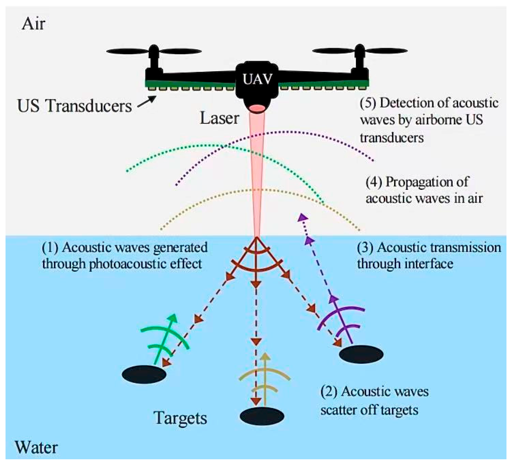
Figure 6. Fitzpatrick’s conceptual experimental system diagram [41].
Water 17 03285 g006
Figure 7. (a) Schematic diagram of Fitzpatrick proof-of-concept system; (b) experimental design drawings; (c) time domain analysis diagram of acoustic features; (d) laser–acoustic imaging [41].
Water 17 03285 g007
Figure 8. (a) The experimental system used by Zong, S. et al. in 2010 [90]; (b) Structure diagram of laser acoustic underwater target detector [92].
Water 17 03285 g008
Figure 9. Finite element numerical simulation results: (a) the distribution of sound pressure on the ocean surface; (b) sound pressure distribution on a 15° inclined plane; (c) wave surface sound pressure distribution; (d) comparison of sound pressure signals at the same position under different water surfaces; (e) comparison of Time-Domain Signal of Acoustic Pressure after SAFT Scanning with Single Laser and Multi-Source Lasers [93].
Water 17 03285 g009
Table 1. Comparison of Underwater Detection Technology.
MethodTypical PlatformsStrengthsCore ConstraintsRepresentative Performance
Detection DepthResolution
Active SonarShore-based; surface ships; submarines; airborne; unmanned surface
Vehicle (USV) and unmanned underwater
Vehicle (UUV) [6]
Active emission; long-range; high-resolution [7]Operational exposure; high energy demand; sensitivity to environmental conditions [8]Over 10 km given favorable sound-channel conditions [9,10]At 220–260 kHz, Synthetic aperture sonar (SAS) can deliver 3 cm × 2 cm imaging resolution [11]
Passive SonarCovert operation, low-power, and persistent surveillance capability [12,13]Limited detection range; incomplete information; and constrained sensitivity to low-acoustic-signature targets [14]In general, the propagation depth is within 200 m [15,16]/
Airborne Blue-Green LiDARFixed wing; helicopters; unmanned aerial vehicles (UAVs), satellites [17,18]Highly maneuverable; high-resolution; with strong penetration through water [19]Constrained by water turbidity; strongly affected by environmental conditions; high cost [20]Achieved a detection depth of 94 m [21]The spatial resolution is generally between 10 cm and 12 cm (±0.2 m) [22,23]
Laser Doppler vibrometer (LDV)Single-point LDV;
Scanning-LDV;
Continuous-scan LDV (CSLDV);
Full-field / 3-D LDV;
Fiber-coaxial LDV;
Mobile-platform LDV
[24,25,26,27,28]
High accuracy, good linearity, fast dynamic response, wide measurement range, non-contact measurement
[24,29,30,31,32,33,34,35,36]
High equipment cost;
Sensitivity to environmental disturbances;
Laser phase noise [36]
Drone-mounted LDV can achieve a depth of field of approximately 10 m [30]LDVs can achieve femtometer-scale (10−15 m) displacement resolution.
Fiber-Optic HydrophonesMEDUSA multi-cloud demonstrator
[31]
Immunity to electromagnetic interference;
Small size & light weight
Broad bandwidth & multiplexing capability [32,33]
Limited low-frequency response;
Bandwidth ceiling;
Complex optical interrogation
[31,33,34]
3000 m (≈30 MPa hydrostatic pressure)
[35,36]
Laser-Induced AcousticsShore-based; surface ships; airborne [37]Non-contact; high resolution; adaptable to complex marine environments [38]Laser-generated acoustic sources cannot propagate over long distances; the optical-to-acoustic conversion efficiency is low [39]Finite-element simulations indicate that when the pulse reaches a power density of 2.8 × 10¹⁰ W/cm2, the acoustic wave can propagate to a depth of up to 400 m [40]A laser system (wavelength of 10.6 µm and a pulse width of 20 ns, delivering 500 W peak power) can image a 1.3 cm sphere [41]
Table 2. Absorption coefficient of water for different wavelengths of laser [65].
Laser Source λ   ( μ m ) μ   ( c m 1 )
Ruby laser0.69435.3 × 10−3
Nd:YAG laser1.061.4 × 10−3
CO2 laser10.68.7 × 10−3
Er: YAG laser2.941.32 × 10−3
Table 3. Optical breakdown threshold [70].
Pulse Duration
/(ns)
Wavelength
/(µm)
Convergence Angle/°Focused Spot Diameter/(µm)Threshold
Power/(1010 W·cm2)
Threshold Energy
/(J·cm−2)
760.752020.12.31760
61.06335.56.6399
61.06217.74.7285
61.065.414.511650
0.031.06274.64613.7
0.031.068.59.74513.5
0.031.06419.63711.1
0.060.53135.52816.9
3 × 10−30.58165.0852.6
3 × 10−40.58165.14761.4
10−40.58164.411111.1
Table 4. Low atmospheric composition [64].
Constant ComponentVarying Component
NameVolume PercentageNameVolume Percentage
N78.084H0.5 × 10−4
O20.948N2O0.27 × 10−4
Ar0.934CO0.19 × 10−4
water vapor0~0.04Xe0.089 × 10−4
CO0.033NH30.004 × 10−4
Ne18.18 × 10−4SO20.001 × 10−4
O30–13 × 10−4NO20.001 × 10−4
He5.24 × 10−4NO0.0005 × 10−4
CH41.5 × 10−4H2S0.00005 × 10−4
Table 5. Under different laser pulses, the incident laser energy, the laser energy absorbed by water, the sound energy generated, and the efficiency of laser energy conversion into sound energy [49].
nsps
Incident Energy
/mJ
Absorbed Energy
/mJ
Acoustic Energy
/uJ
Energy Conversion Efficiency
/%
Incident Energy
/mJ
Absorbed Energy
/mJ
Acoustic Energy
/uJ
Energy Conversion Efficiency
/%
25201280.641061.70.03
50411400.34159.51.80.02
75641430.22201330.023
100851480.1725154.60.03
Disclaimer/Publisher’s Note: The statements, opinions and data contained in all publications are solely those of the individual author(s) and contributor(s) and not of MDPI and/or the editor(s). MDPI and/or the editor(s) disclaim responsibility for any injury to people or property resulting from any ideas, methods, instructions or products referred to in the content.