Article

Pressure Pulsation and Energy Dissipation Mechanism of a Pump-Turbine Considering Runner Blade Leading Edge Effect

1
China Yangtze Power Co., Ltd., Wuhan 443001, China
2
State Key Laboratory of Hydroscience and Engineering, Department of Energy and Power Engineering, Tsinghua University, Beijing 100084, China
3
China Three Gorges Corporation, Wuhan 430010, China
*
Author to whom correspondence should be addressed.
Water 2025, 17(22), 3184; https://doi.org/10.3390/w17223184
Submission received: 24 September 2025 / Revised: 28 October 2025 / Accepted: 4 November 2025 / Published: 7 November 2025
(This article belongs to the Section Hydraulics and Hydrodynamics)

Abstract

Efficiency and stability significantly determine the operating quality of a pump-turbine, and the runner blade leading edge angle (BLEA) is a critical factor influencing these performance indicators. In this study, numerical simulations were conducted to investigate the pressure pulsation characteristics and energy dissipation mechanisms within a pump-turbine under three different runner blade leading edge angles (standard, +15°, and −15°). The findings indicate that the blade angle has little effect on efficiency, with the maximum relative difference of 0.5%. When compared to the original blade geometry, the variant whose blade inclines 15° toward the rotational direction in turbine mode demonstrates superior performance both in terms of efficiency and in reducing pressure pulsations, under both turbine and pump operational modes. Additionally, it was observed that energy dissipation locations vary notably depending on the flow direction: when operating as a turbine, prominent dissipation occurs within the runner region, while in pump mode, significant energy losses are primarily concentrated in the stay vanes and guide vanes. The insights presented in this work provide beneficial guidance for optimizing pump-turbine designs, enhancing efficiency and stability, and ultimately contributing to sustainable development in pumped-storage power plants.

1. Introduction

The pump-turbine is a central component in pumped-storage power stations and significantly impacts the system’s efficiency and operational stability. Nevertheless, complex unsteady flow phenomena linked to the runner blade leading edge often amplify issues such as pressure pulsations and energy dissipation, particularly at off-design operating conditions, potentially causing vibration and noise problems in pump-turbine units [1,2,3,4,5]. Hence, detailed studies focusing on the runner blade leading edge effect and its role in influencing the mechanisms of pressure pulsation and energy dissipation are crucial. Such research can provide valuable insights for improving the hydraulic design and achieving enhanced operational characteristics.
Pressure pulsation is a common occurrence in pump-turbines, primarily caused by rotor–stator interactions (RSIs), vortex shedding phenomena occurring within the draft tube, and cavitation effects [6,7,8]. Given that the runner blade leading edge is a crucial part for energy conversion, its geometric shape and hydraulic performance greatly influence how pressure pulsations develop and propagate [9,10]. Poor designs in the leading edge region can induce flow separation and secondary flow patterns, further intensifying local pressure fluctuations [11,12,13]. Furthermore, cavitation around the blade leading edge region causes vapor bubbles to form and subsequently collapse, creating intense localized pressure impulses that worsen the pulsations [14,15,16]. These resulting pressure disturbances may propagate upstream into the draft tube, adversely affecting the overall hydraulic system stability [17,18].
Energy dissipation in pump-turbines is inevitable and mainly results from frictional losses, flow separation, vortex formation, and cavitation phenomena [19,20,21]. Specifically, at the runner blade leading edge, energy dissipation is concentrated in three aspects: firstly, frictional resistance between the blade surface and the water flow, which depends on surface roughness and velocity; secondly, flow separation and secondary flows at the leading edge, which intensify turbulence and thereby increase energy loss [11,22]; and thirdly, cavitation at the leading edge, where the collapse of bubbles dissipates significant energy and reduces overall conversion efficiency [14,15]. To more accurately evaluate energy dissipation at the runner blade leading edge, entropy generation theory is frequently applied to calculate entropy generation rates, enabling the visualization of the locations and magnitudes of energy losses [11,23,24].
The runner blade leading edge effect significantly impacts pump-turbine performance, influenced by blade configuration, operating state, rotation rate, and guide vane opening [25,26,27,28,29,30,31,32]. Blade geometry is critical, as variations directly affect flow separation and cavitation [9,33]. Off-design operation increases the incidence angle, intensifying cavitation and flow separation [6]. Increased rotation elevates cavitation potential and frictional losses [34]. Guide vane opening indirectly influences flow patterns by modifying water volume and inflow direction [20,35]. Blade leading edge shape (radius, angle) affects fluid acceleration and pressure, influencing cavitation [27,29]. Optimizing this shape delays cavitation and improves turbine efficiency. High-pressure side optimization reduces pressure fluctuations [9]. Off-design conditions increase runner blade load and flow separation. Guide vane opening’s impact is seen in energy storage/generation studies, with shape affecting performance [20,28]. Blade leaning influences hydraulic excitation [26]. Runner blade number affects flow characteristics [25]. Comprehensive consideration is vital for pump-turbine design. Recent studies focus on the blade’s low-pressure edge angle’s impact on cavitation [30] and guide vane opening’s effect on pressure pulsation [35]. Numerical simulations of large pump-turbines under various conditions [31] and guide vane opening effects during startup [32] provide insights for design and optimization.
To address pressure pulsation and energy dissipation caused by the runner blade leading edge effect, researchers have proposed multiple optimization strategies. Optimization of the blade leading edge geometry—such as employing nonlinear shapes or increasing the leading edge radius—can mitigate flow separation and cavitation [9,27,36]. The adoption of advanced materials and surface treatment technologies further enhances blade wear and cavitation erosion resistance. In addition, hydraulic optimization techniques such as genetic algorithms and fuzzy logic are increasingly used for blade profile optimization, thus improving overall hydraulic performance [2,37]. Modifications to the design and arrangement of guide vanes can also enhance the flow entering the runner, reducing pressure pulsation and energy loss at the blade leading edge [20].
The advancement and widespread application of computational fluid dynamics (CFD) technology have substantially expanded its use in the analysis of pump-turbines, particularly for examining the effects associated with the runner blade leading edge [34]. CFD enables detailed analysis of flow structures, pressure distributions, and cavitation characteristics at the leading edge, providing theoretical guidance for blade design optimization. However, the accuracy of CFD depends on turbulence models, mesh quality, and boundary conditions, making validation against experimental data imperative [38,39]. Furthermore, transient CFD simulations can capture unsteady phenomena such as vortex shedding and pressure pulsations, but these come at a high computational cost [40,41]. Thus, future research should focus on developing more efficient and accurate simulation methods, in tandem with experimental approaches, to uncover the complex flow mechanisms at the runner blade leading edge.
Despite substantial achievements in clarifying the impact of the runner blade leading edge, some complicated aspects, such as the mechanisms governing pressure pulsation and energy dissipation, have not yet been comprehensively explored. The current work adopts numerical simulation techniques to investigate the mechanisms of pressure pulsation and energy dissipation in a pump-turbine, comparing three different runner blade leading edge angles. The insights derived from this investigation can facilitate enhancements in the stability and operating efficiency of pump-turbines, providing further support for the sustainable growth and adoption of pumped-storage power facilities.

2. Numerical Model and Methodology

2.1. Governing Equations

2.1.1. Fluid Dynamics

The internal flow within the pump-turbine prototype is treated as an unsteady, three-dimensional, incompressible turbulent flow. To accurately represent the full internal flow characteristics of the pump-turbine, numerical simulations adopt the Reynolds-averaged Navier–Stokes (RANS) equations, the accuracy of which has been proven in many studies [42,43]. To effectively capture turbulence, the SST k - ω turbulence model is chosen as it provides reliable predictions of flow separation onset and magnitude under conditions involving adverse pressure gradients, and has proven capability in modeling turbulent shear stress transport accurately [17,44].
In the present work, the definitions of the runner’s rotational frequency ( f n ), pressure pulsation ( p n ), and the relative pressure pulsation amplitude ( p ) are given below:
f n = n 60
p n = p ρ g
p = A / ρ g H r · 100 %
wherein n denotes the runner’s rotational speed, p indicates the pressure pulsation value, ρ is the fluid density, g represents gravitational acceleration, A corresponds to the amplitude of pressure pulsation obtained via FFT analysis, and H r is the rated head of the pump-turbine.

2.1.2. Theory of Entropy Production

Entropy production theory, derived from the second law of thermodynamics, has been widely utilized to evaluate and interpret energy dissipation processes occurring within hydraulic machinery [45,46,47]. In a given region, the local total entropy production S ˙ D can be decomposed into three primary types: the direct entropy production S ˙ D ¯ , the entropy production due to turbulent dissipation (EPTD) S ˙ D , and the entropy production associated with wall effects S ˙ w . The local total entropy production can thus be expressed as follows [48]:
S ˙ D = S ˙ D ¯ + S ˙ D + S ˙ w
S ˙ D ¯ = μ T u ¯ y + v ¯ x 2 + u ¯ z + w ¯ x 2 + w ¯ y + v ¯ z 2 + 2 μ T u ¯ x 2 + v ¯ y 2 + w ¯ z 2
S ˙ D = μ e f f T u y + v x 2 + u z + w x 2 + w y + v z 2 + 2 μ e f f T u x 2 + v y 2 + w z 2
S ˙ W = τ w · u p T
In Equations (5)–(7), μ e f f denotes the effective viscosity, defined as the sum of molecular viscosity μ and turbulent viscosity μ t . The parameters u ¯ , v ¯ , and w ¯ represent the time-averaged velocity components along the x , y , and z directions, respectively, while u , v , and w refer to the velocity fluctuations (pulsation velocities) in the same coordinate directions. T stands for temperature. Wall shear stress is denoted by τ w , and the velocity at the first grid node adjacent to the wall is labeled as u p .

2.2. Numerical Model

The pump-turbine under investigation is characterized by a rated power ( P r ) of 350 MW, rated rotational speed ( n r ) of 600 rpm, and rated head ( H r ) of 710 m, which can be considered as a representative of high head, large capacity, and high-speed pump-turbines. The hydraulic structural model comprises a spiral casing, runner (with 11 blades), and both stationary vanes: specifically, 20 guide vanes and 20 stay vanes, as well as a draft tube. Detailed structural features, such as clearances between the runner and the head cover and between the runner and bottom ring, have been incorporated. Furthermore, a pressure-balancing pipe connecting the crown gap with the draft tube is modeled [49]. A comprehensive, three-dimensional geometric model of this pump-turbine arrangement is illustrated in Figure 1a.
To systematically investigate how runner blade leading edge angles influence pressure pulsations and energy loss mechanisms, two alternative blade geometries were developed from the baseline blade shape (Blade A). Blade B is modified by adjusting its leading edge 15° toward the rotational direction in turbine mode, while Blade C is adjusted 15° toward the rotational direction in pump mode. These blade variants are depicted schematically in Figure 1b.

2.3. Boundary Conditions

Transient numerical simulations were conducted across a range of operational settings, including turbine modes (from 50% P r to 100% P r ) and pump modes (rated operating head and maximum-head scenarios), allowing comprehensive analyses concerning the influences of the blade leading edge angle (BLEA) and different operating conditions. In turbine operation, boundary conditions were defined by setting a pressure inlet at the spiral casing entry, with specified total pressure reflecting the chosen head and flow direction perpendicular to the inlet boundary, complemented by a static pressure outlet boundary condition at the draft tube exit. For the pump operation scenario, boundary conditions were reversed; a mass flow inlet boundary condition specifying flow perpendicular to the inlet plane was applied at the draft tube, accompanied by a fixed static pressure boundary at the spiral casing outlet. Throughout the entire hydraulic model, no-slip conditions were imposed on all solid walls.
Consistent rotational speed was set equal to rated rotation, and the sliding mesh technique was employed, allowing rotational runner grids to interact dynamically with stationary grids of the guide vanes and the draft tube. Consistent data transfer across non-matching interfaces was ensured by implementing conservative interpolation methods; velocity and turbulence quantities were interpolated, while pressure and flux continuity were maintained via numerical integration. Specifically, stage-type interfaces were set up connecting the spiral casing to stay vanes and the stay vanes to guide vanes, whereas sliding-type interfaces connected guide vanes to the rotating runner and the runner to the downstream draft tube section.
The turbulence in the flow field was modeled using the SST k - ω turbulence approach for all simulations, which has been verified in many studies. Numerical convergence criteria were set strictly, with residuals for mass, momentum, and turbulence equations converged when reduced below 1 × 10⁻⁵. Steady-state simulation results provided the initial starting point for the unsteady calculations, ensuring appropriate continuity in the flow field initialization. The transient simulations were carried out over a duration corresponding to 10 full revolutions of runner rotation, employing a fixed timestep of 1/200 of a single runner rotational period. The final 5 rotation cycles were selected for in-depth analysis, thus excluding initial transient disturbances. All computations were conducted using ANSYS CFX 18.0, a finite-volume CFD solver validated extensively for turbomachinery simulations.
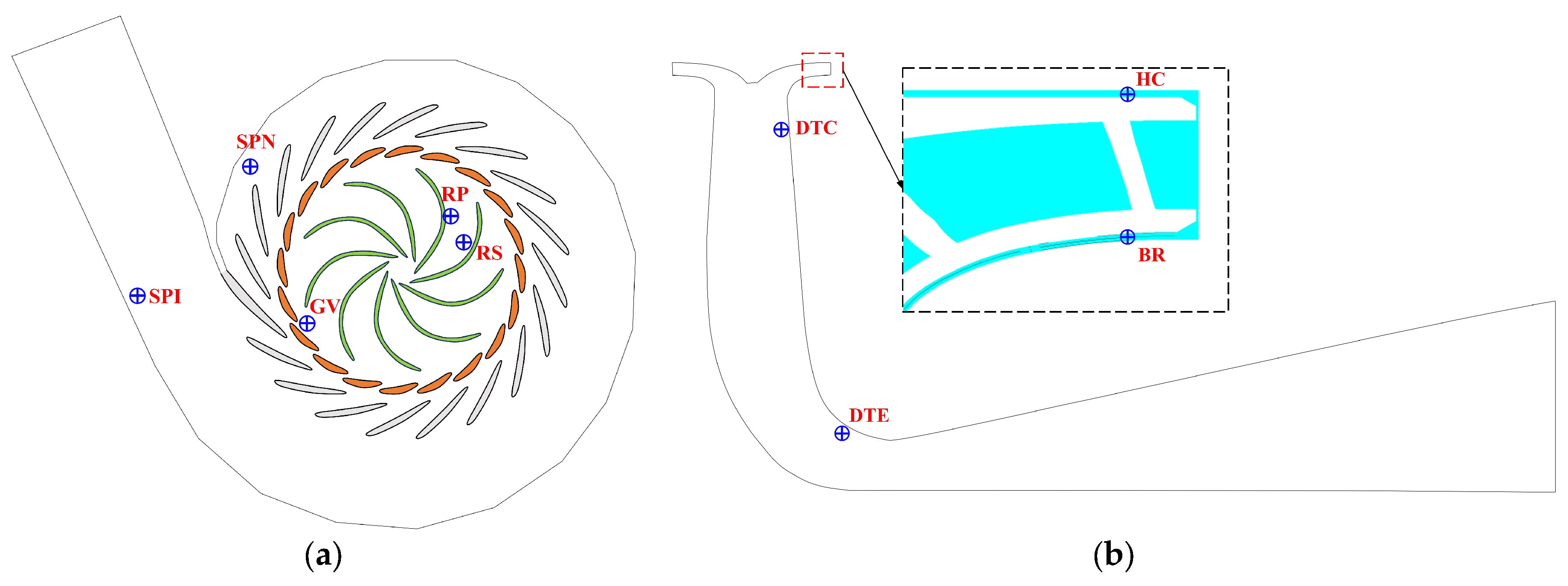
To quantify and analyze pressure pulsation characteristics in the pump-turbine, strategic pressure monitoring points were carefully established throughout different sections of the fluid domain. Four stationary monitoring positions were placed at the guide vane (GV), head cover (HC), bottom ring (BR), and draft tube (DT); moreover, two additional pressure monitoring points were located on a runner blade—positioned, respectively, on its pressure surface (RP) and suction surface (RS)—which rotated with the runner. These monitoring locations are illustrated in Figure 2. Pressure data recording was conducted at each computational timestep, thus yielding a sampling interval of ΔT = T/200 (0.0005 s).

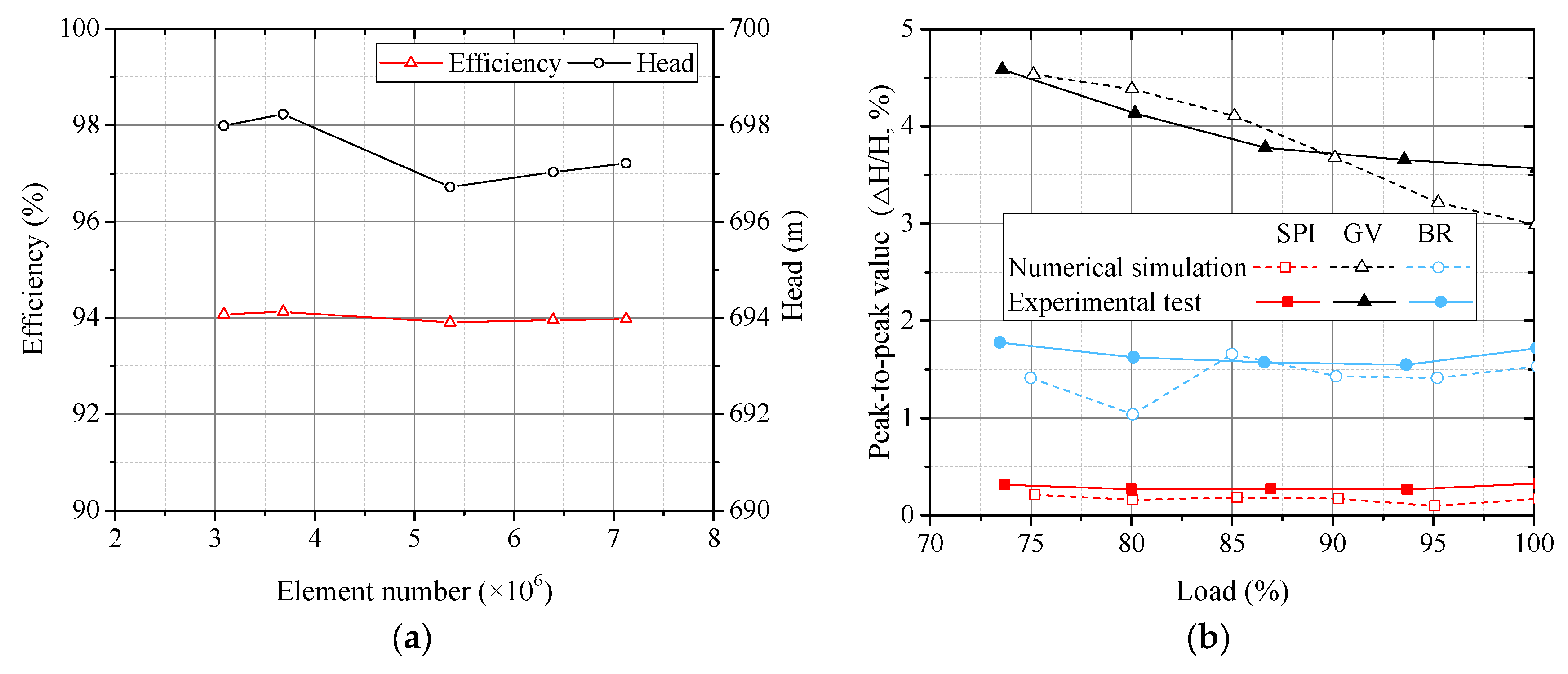
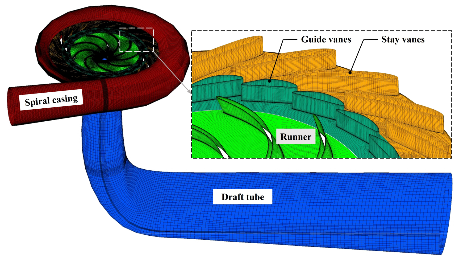
2.4. Grid-Independent Checks and Method Validation

The accuracy of CFD simulations depends substantially on mesh resolution [48]. Therefore, a mesh sensitivity analysis was conducted to assess and minimize the influence of grid density on numerical results. For Blade A, the efficiency ( η ) and head ( H ) in turbine mode obtained using five mesh sizes with varying element counts are presented in Figure 3a. After reaching a mesh density of approximately 6.3 × 10⁶ elements, further mesh refinement resulted in changes in efficiency and head values of less than 0.03%, indicating adequate mesh independence beyond this point. Additionally, Figure 3b illustrates a comparison of computational (using the model with 6.3 × 10⁶ elements) and experimental results of pressure pulsation in turbine mode for load conditions from 50% to 100% of the rated power ( P r ). Numerical results exhibited a maximum deviation from the experimental data of less than 2.24%, demonstrating good reliability and accuracy of the numerical modeling approach. Consequently, a final mesh comprising approximately 6.3 × 10⁶ elements was selected as optimal, as depicted in Figure 4.

3. Results and Discussion

3.1. Hydraulic Performance

3.1.1. Efficiency at Turbine and Pump Modes

Figure 5 depicts the relative efficiencies of the three blade configurations (A, B, and C) under turbine and pump operating conditions, normalized by the maximum efficiency value achieved. As observed, efficiency differences among the models are generally minimal. In particular, Blade A and Blade B exhibit very similar performance characteristics across the full range. Blade C demonstrates notably higher efficiency at the 75% P r turbine operating condition but shows relatively lower efficiency during maximum-head conditions in pump mode.

3.1.2. Flow Characteristics

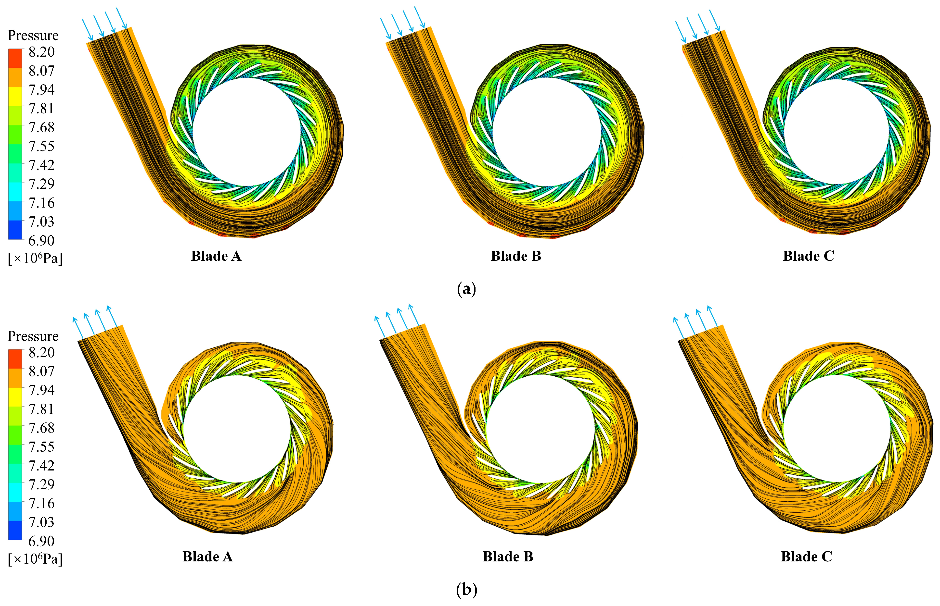
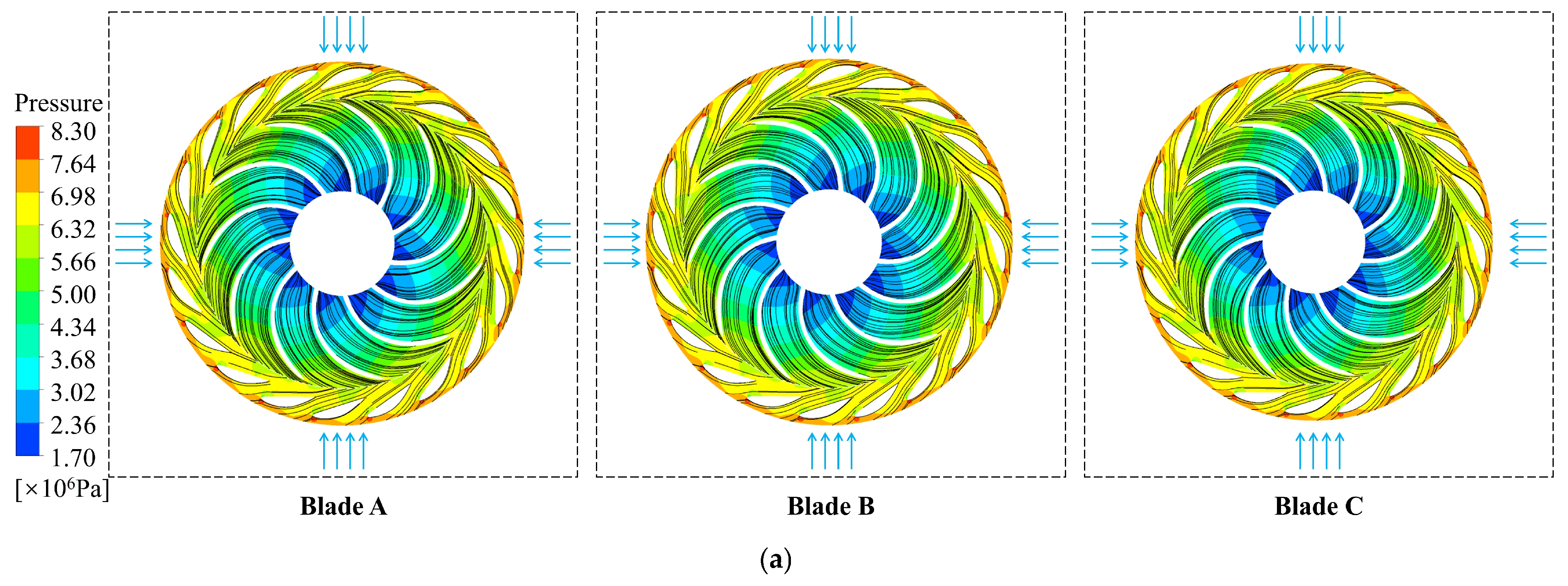
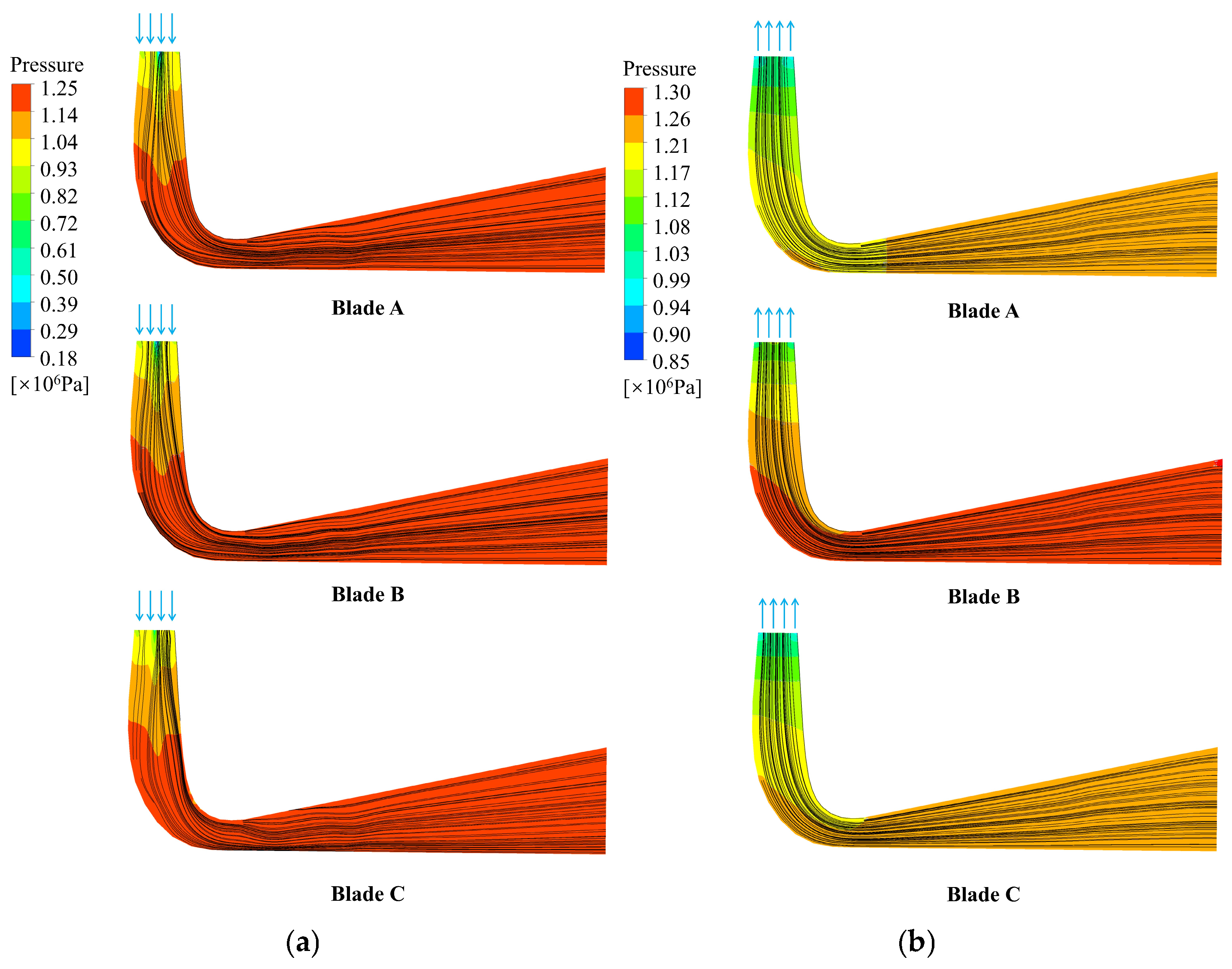
Figure 6, Figure 7 and Figure 8 illustrate the pressure distribution and flow streamlines within different flow-passage sections at the rated (100% P r ) turbine condition and at the rated head condition in pump mode. Specifically, Figure 6 provides views of the spiral casing and stay vanes, Figure 7 illustrates the guide vanes and runner, and Figure 8 represents the draft tube region. It is clearly shown that flow patterns across all blade designs remain relatively stable, as indicated by smooth streamlines. However, a significant difference in pressure distributions within the draft tube is evident among the models. Specifically, Blade B exhibits a steeper pressure gradient yet contains smaller low-pressure regions compared to Blades A and C under pump-mode conditions. This indicates a lower cavitation potential and enhanced flow stability for Blade B compared to Blade A and Blade C.

3.2. Pressure Pulsation Characteristics

3.2.1. Case Study of Blade A

Presented in Figure 9 are the pressure pulsation time history curves and associated frequency spectra at nine monitoring points for the turbine mode at 100% P r . At the spiral casing locations SPI and SPN, rotor–stator interaction (RSI) dominates, with the primary frequency component at two times the blade passing frequency (22 f n ). For the monitoring points RP and RS on the runner, the pressure pulsation peak is governed by the guide vane passing frequency (20 f n ). In contrast, at the GV monitoring location within the guide vanes, the dominant frequency is the runner blade passing frequency (11 f n ). Within the draft tube (DTC and DTE), although the dominant RSI frequency (22 f n ) appears clearly, lower-frequency fluctuations also emerge, attributable to complex flow structures such as vortex ropes. Lastly, the monitoring locations HC (head cover) and BR (bottom ring) are dominated by blade passing frequencies (22 f n ).
Figure 10 illustrates the corresponding time histories and frequency spectra of pressure pulsations at the same nine monitoring points under the rated-head pump-mode operation. Here, low-frequency pulsations dominate overall. The prevalent frequencies are identified as follows: 0.25 f n at points SPI, SPN, DTC, DTE, HC, and BR, the rotational frequency 1 f n at the runner surfaces RP and RS, and 0.125 f n at the guide vane (GV). Despite the dominance of low-frequency fluctuations, clear RSI frequency components (20 f n , 11 f n , or 22 f n ) are also present throughout the flow passage.

3.2.2. Statistical Analysis Under Three BLEAs

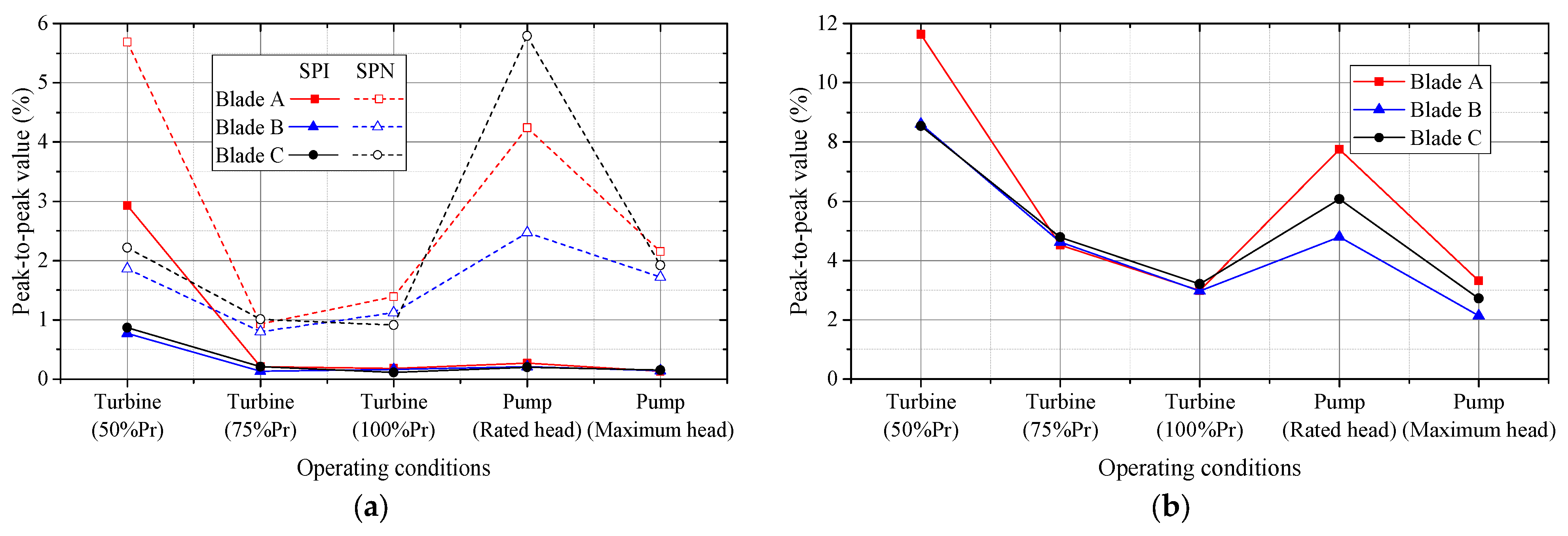
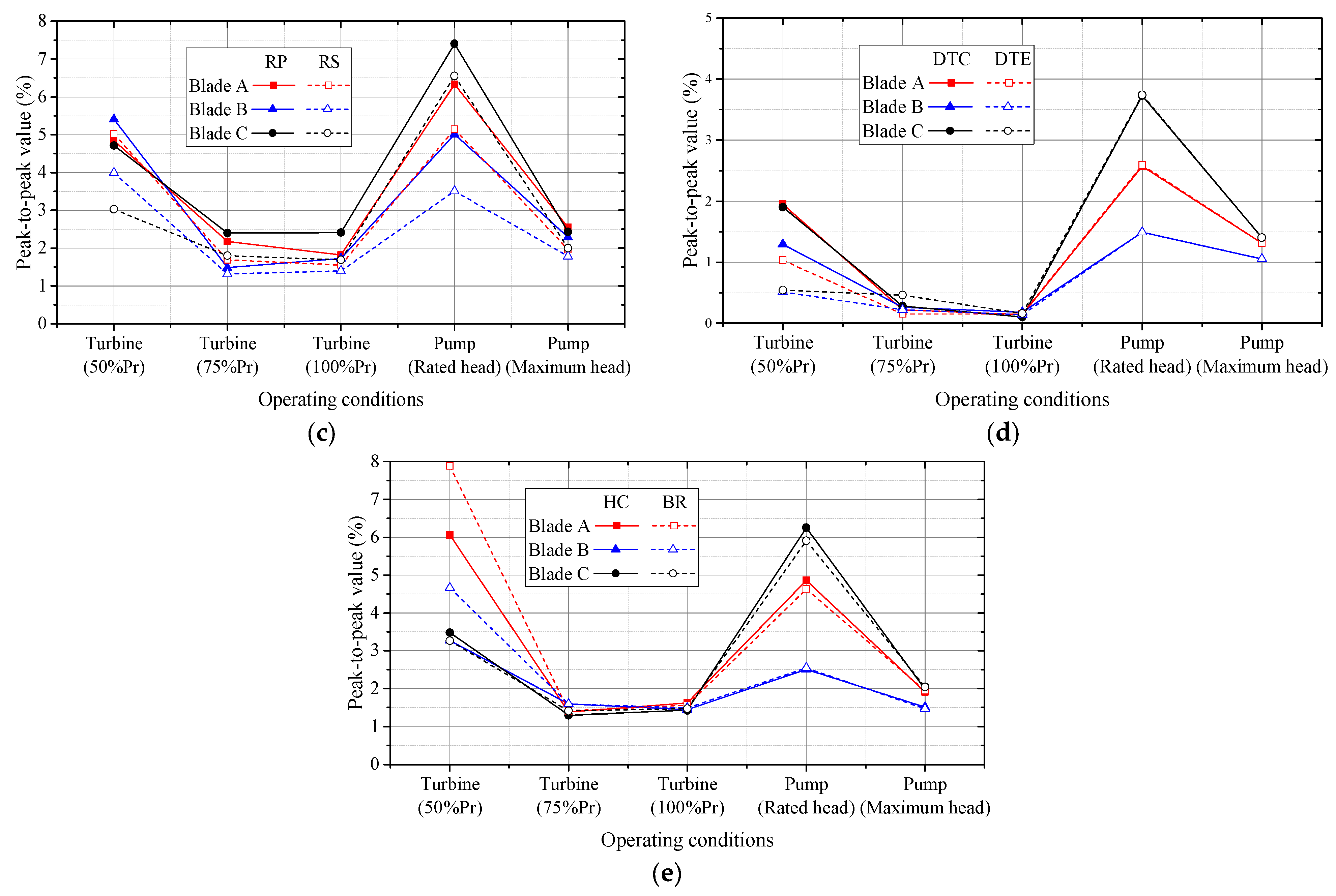
Comparisons of relative peak-to-peak pressure pulsation values across various operating points are depicted in Figure 11. Within turbine-mode operations from 75% to 100% P r , pressure pulsations for Blades A, B, and C show insignificant variation. However, at the lower 50% P r condition, Blade A generates appreciably higher pressure pulsations at most monitoring points than either Blade B or Blade C. Furthermore, except at points SPI and GV, Blade C consistently exhibits the highest peak-to-peak pulsations, while Blade B produces generally lower levels, indicating superior performance in flow stability.

3.3. Mechanism Analysis Based on Energy Dissipation

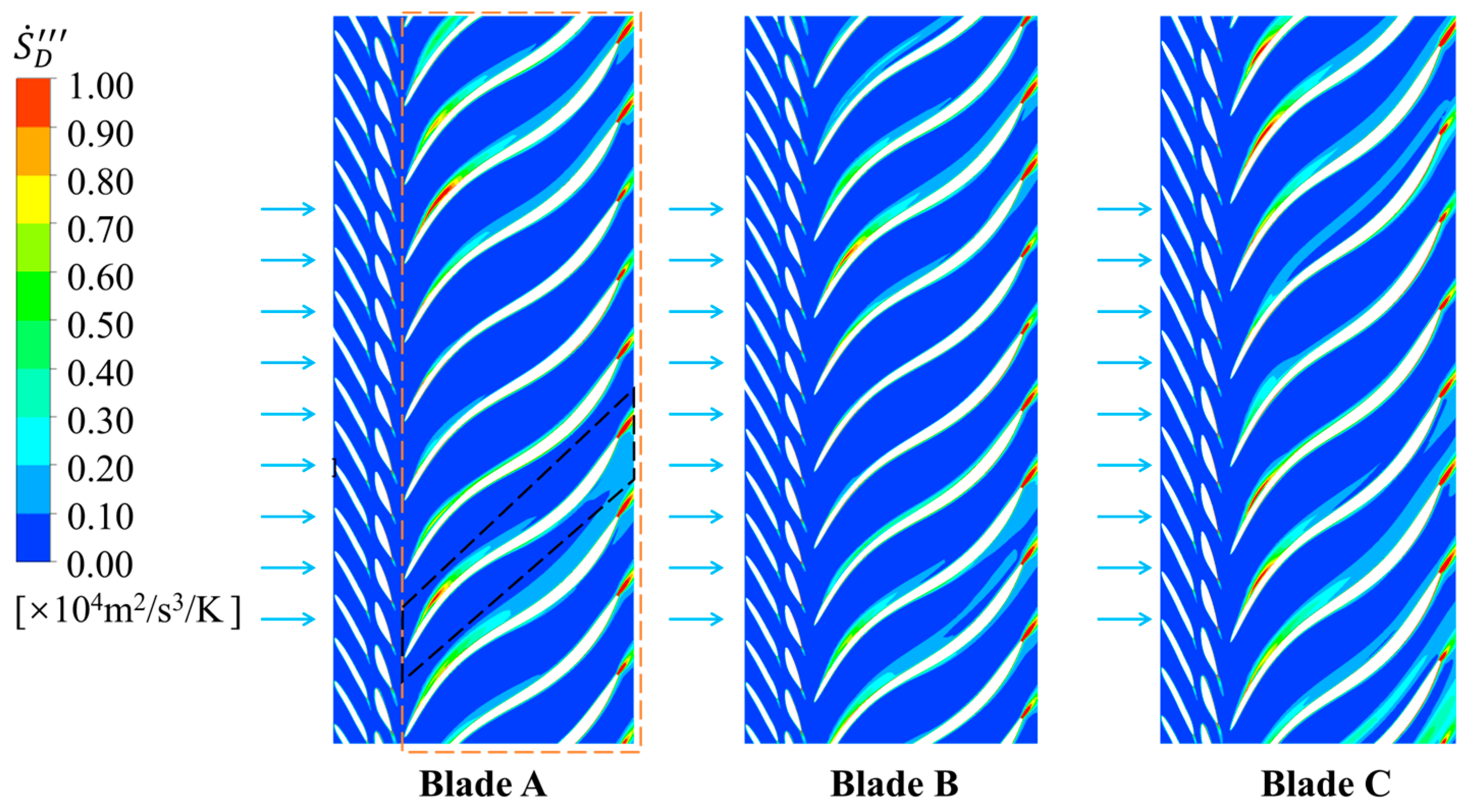
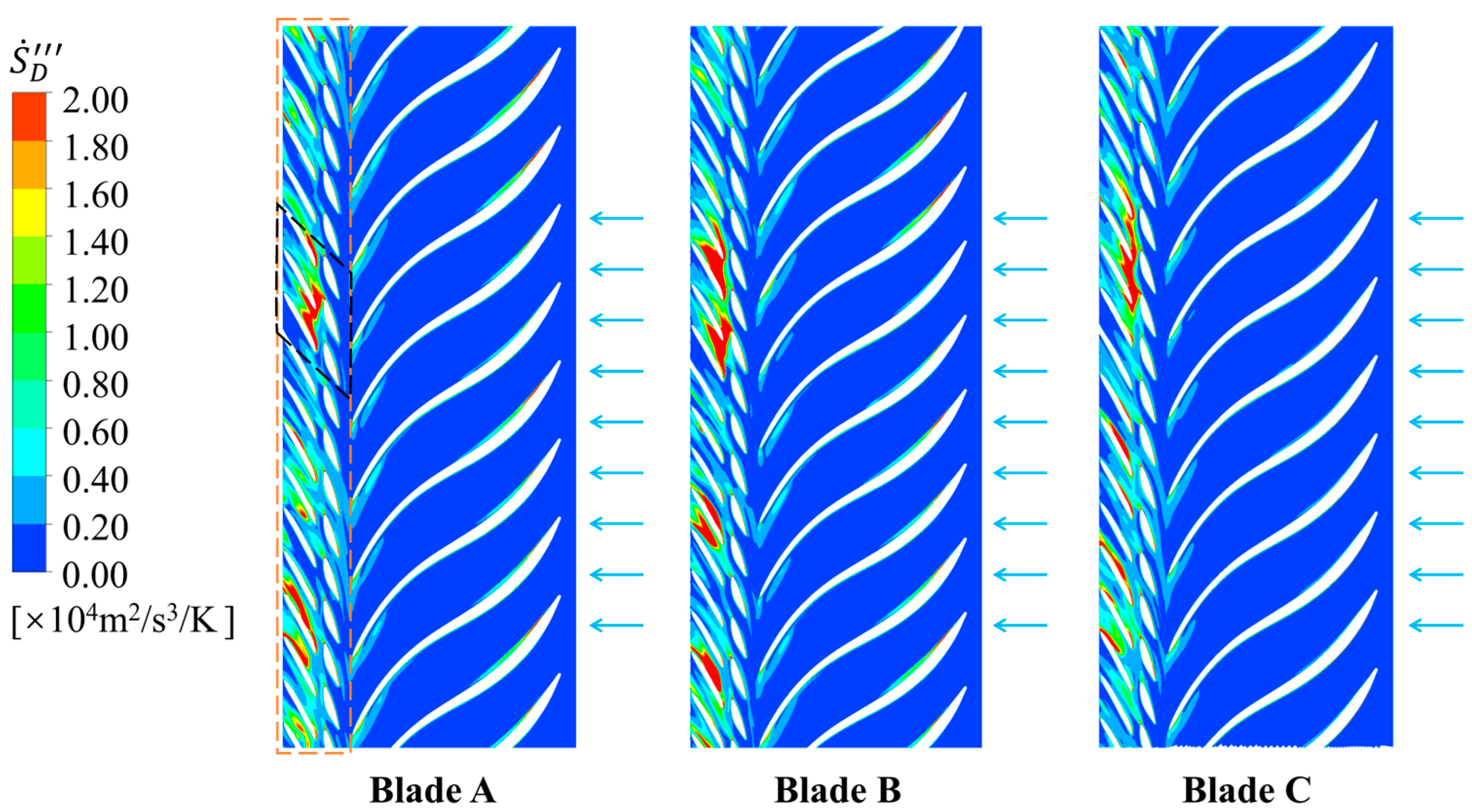
The local total entropy production in stay vanes to runner at 100% P r of turbine mode is shown in Figure 12, and the local total entropy production in runner to stay vanes at the rated head of pump mode is shown in Figure 13. As one can see, the entropy production distribution shows consistent dissipation regions (runner in turbine mode, stay vanes in pump mode) with the literature [45], confirming the rationality of the entropy calculation method. In addition, the energy dissipation is greatly affected by the flow direction, which manifested obvious energy dissipation in the runner in turbine mode and obvious energy dissipation in stay vanes and guide vanes in pump mode. The energy dissipation in pump mode is larger than that in turbine mode, and the maximum value of local total entropy production S ˙ D in pump mode is about double of that in turbine mode. In turbine mode, the maximum value of entropy production of Blade A to Blade C is 2.1 × 10⁴, 1.8 × 10⁴, 2.3 × 10⁴ m2/s3/K, respectively, and it is 4.5 × 10⁴, 4.9 × 10⁴, 4.7 × 10⁴ m2/s3/K in pump mode. In addition, the energy dissipation of Blade B is lower in turbine mode, but larger in pump mode.

3.4. Discussion

Although some progress has been made in understanding the runner blade leading edge effect, significant challenges remain—including the accurate prediction and control of cavitation, effective mitigation of pressure pulsation propagation, and the simultaneous achievement of operational stability and high efficiency. Future directions should include the development of advanced cavitation and turbulence models to improve CFD accuracy [50], research on novel blade materials and surface treatments to enhance erosion resistance [51], and the use of intelligent multi-objective optimization algorithms for blade design [52,53]. Strengthening experimental research, especially field tests on prototype units, is vital for validating simulations and deepening insight into real-world flow phenomena [54,55,56]. In addition, the mechanical safety, manufacturing cost, and material selection of different BLEA models should be studied to connect the mechanism analysis with design concerns. Through persistent research and technological innovation, the operational efficiency and stability of pump-turbines will continue to advance, supporting the sustainable development of pumped-storage power stations.

4. Conclusions

Efficiency and stability are key indicators for evaluating pump-turbine performance, wherein the runner blade leading edge angle (BLEA) plays an important role. Although notable progress has been made in understanding the runner blade leading edge effect, significant challenges remain as the pressure pulsation and energy dissipation mechanism have not been thoroughly studied. This paper analyzed the pressure pulsation and energy dissipation mechanism of a pump-turbine under three runner blade leading edge angles using numerical methods, and the main conclusions can be drawn as follows:
(a)
The BLEA has little effect on efficiency in different operating conditions but will affect the flow stability. Blade B, which inclines 15° to the right relative to Blade A, is better in turbine mode and pump mode in terms of efficiency and pressure pulsation.
(b)
The pressure pulsation in flow passage was mainly affected by the RSI at 100% P r in turbine mode, and the dominant frequency is mainly once or twice that of the runner blade passing frequency of 11 f n or 22 f n and of the guide vanes passing frequency of 20 f n .
(c)
The energy dissipation is greatly affected by the flow direction, which manifested obvious energy dissipation in the runner in turbine mode and obvious energy dissipation in the stay vanes and guide vanes in pump mode. The energy dissipation in pump mode is larger than that in turbine mode, and the maximum value of local total entropy production S ˙ D in pump mode is about double of that in turbine mode. In addition, the energy dissipation of Blade B is lower in turbine mode, but larger in pump mode.
The results are helpful for improving the operational efficiency and stability of pump-turbines and subsequently supporting the sustainable development of pumped-storage power stations.

Author Contributions

Conceptualization, formal analysis, investigation, B.L. and Y.L.; writing—original draft preparation, J.O. and X.C.; writing—review and editing, S.L. and H.Z. All authors have read and agreed to the published version of the manuscript.

Funding

The authors declare that this study received funding from the project of China Yangtze Power Co., Ltd., grant number Z342402002. The funder was not involved in the study design, collection, analysis, interpretation of data, the writing of this article, or the decision to submit it for publication.

Data Availability Statement

The original contributions presented in this study are included in the article. Further inquiries can be directed to the corresponding author.

Conflicts of Interest

The authors Bin Liu, Xupeng Chen, and Shizhe Liu were employed by China Yangtze Power Co., Ltd. and the authors Jinhui Ouyang and Han Zhang were employed by China Three Gorges Corporation. The remaining authors declare that the research was conducted in the absence of any commercial or financial relationships that could be construed as potential conflicts of interest.

References

  1. Guo, P.; Li, Y.; Sun, L. Dynamic behavior and energy dissipation analysis of pump turbine in unstable S characteristic zone. J. Energy Storage 2024, 102, 114275. [Google Scholar] [CrossRef]
  2. Zhang, F.; Xiao, R.; Zhu, D.; Liu, W.; Tao, R. Pressure pulsation reduction in the draft tube of pump turbine in turbine mode based on optimization design of runner blade trailing edge profile. J. Energy Storage 2023, 59, 106541. [Google Scholar] [CrossRef]
  3. Shi, G.; Wang, N.; Liu, H.; Wen, H.; Huang, Z.; Wu, J. Study on the flow and pressure pulsation characteristics in the hump region of pump-turbine based on C-shaped blade design. J. Energy Storage 2025, 119, 116246. [Google Scholar] [CrossRef]
  4. Olimstad, G.; Nielsen, T.; Børresen, B. Dependency on Runner Geometry for Reversible-Pump Turbine Characteristics in Turbine Mode of Operation. J. Fluids Eng. 2012, 134, 121102. [Google Scholar] [CrossRef]
  5. Cao, J.; Luo, Y.; Mirza Umar, B.; Wang, W.; Wang, Z. Influence of structural parameters on the modal characteristics of a Francis runner. Eng. Fail. Anal. 2022, 131, 105853. [Google Scholar] [CrossRef]
  6. Binama, M.; Su, W.-T.; Cai, W.-H.; Li, X.-B.; Muhirwa, A.; Li, B.; Bisengimana, E. Blade trailing edge position influencing pump as turbine (PAT) pressure field under part-load conditions. Renew. Energy 2019, 136, 33–47. [Google Scholar] [CrossRef]
  7. Wang, W.; Tai, G.; Shen, J.; Pei, J.; Yuan, S. Experimental investigation on pressure fluctuation characteristics of a mixed-flow pump as turbine at turbine and runaway conditions. J. Energy Storage 2022, 55, 105562. [Google Scholar] [CrossRef]
  8. Gao, B.; Zhang, N.; Li, Z.; Ni, D.; Yang, M. Influence of the Blade Trailing Edge Profile on the Performance and Unsteady Pressure Pulsations in a Low Specific Speed Centrifugal Pump. J. Fluids Eng. 2016, 138, 051106. [Google Scholar] [CrossRef]
  9. Li, D.; Qin, Y.; Wang, J.; Zhu, Y.; Wang, H.; Wei, X. Optimization of blade high-pressure edge to reduce pressure fluctuations in pump-turbine hump region. Renew. Energy 2022, 181, 24–38. [Google Scholar] [CrossRef]
  10. Yulin, F.; Xuhe, W.; Baoshan, Z.; Dongyue, Z.; Xijun, Z. Mechanism study on pressure fluctuation of pump-turbine runner with large blade lean angle. IOP Conf. Ser. Earth Environ. Sci. 2016, 49, 42006. [Google Scholar] [CrossRef]
  11. Lu, J.; Tao, R.; Xiao, W.; Gui, Z.; Zhu, D.; Xiao, R.; Liu, W. Analysis of flow and energy dissipation in pump turbine with small guide vane opening. Eng. Appl. Comput. Fluid Mech. 2024, 18, 2421481. [Google Scholar] [CrossRef]
  12. Luo, H.; Tao, R.; Yang, J.; Wang, Z. Influence of Blade Leading-Edge Shape on Rotating-Stalled Flow Characteristics in a Centrifugal Pump Impeller. Appl. Sci. 2020, 10, 5635. [Google Scholar] [CrossRef]
  13. Cao, J.; Yang, G.; Luo, Y.; Chen, J.; Liao, R.; Wang, Z. Failure investigation of a Kaplan turbine blade lever. Eng. Fail. Anal. 2022, 142, 106840. [Google Scholar] [CrossRef]
  14. Zhu, D.; Xiao, R.; Liu, W. Influence of leading-edge cavitation on impeller blade axial force in the pump mode of reversible pump-turbine. Renew. Energy 2021, 163, 939–949. [Google Scholar] [CrossRef]
  15. Tao, R.; Jin, F.; Wu, Y.; Lu, Z.; Xiao, R.; Zhu, D.; Liu, W. Analyses of the spatial and temporal features of the blade pressure-side cavitation in a pump-turbine runner in the pump mode. Energy Sci. Eng. 2022, 10, 3125–3137. [Google Scholar] [CrossRef]
  16. Xiang, R.; Wang, T.; Fang, Y.; Yu, H.; Zhou, M.; Zhang, X. Effect of blade curve shape on the hydraulic performance and pressure pulsation of a pump as turbine. Phys. Fluids 2022, 34, 085130. [Google Scholar] [CrossRef]
  17. Li, Y.; Hao, P.; Zhang, Z.; Zhang, L.; Hai, H.; Zhang, H.; Wang, X.; Wang, J.; Zhao, Z.; Peng, P. Characterization of Pressure Pulsation Propagation in a Pump-Turbine Based on the Same-Frequency Tracking Method. Energy Sci. Eng. 2025, 13, 3588–3604. [Google Scholar] [CrossRef]
  18. Gao, Z.; Zhu, W.; Meng, L.; Zhang, J.; Zhang, F.; Pan, L.; Lu, L. Experimental Study of the Francis Turbine Pressure Fluctuations and the Pressure Fluctuations Superposition Phenomenon Inside the Runner. J. Fluids Eng. 2017, 140, 041208. [Google Scholar] [CrossRef]
  19. Pei, J.; Shen, J.; Wang, W.; Yuan, S.; Zhao, J. Evaluating hydraulic dissipation in a reversible mixed-flow pump for micro-pumped hydro storage based on entropy production theory. Renew. Energy 2024, 225, 120271. [Google Scholar] [CrossRef]
  20. Lu, Z.; Tao, R.; Yao, Z.; Liu, W.; Xiao, R. Effects of guide vane shape on the performances of pump-turbine: A comparative study in energy storage and power generation. Renew. Energy 2022, 197, 268–287. [Google Scholar] [CrossRef]
  21. Deng, Y.; Xu, J.; Li, Y.; Zhang, Y.; Kuang, C. Research on Energy Loss Characteristics of Pump-Turbine during Abnormal Shutdown. Processes 2022, 10, 1628. [Google Scholar] [CrossRef]
  22. Li, G.; Wang, Y.; Cao, P.; Zhang, J.; Mao, J. Effects of the Splitter Blade on the Performance of a Pump-Turbine in Pump Mode. Math. Probl. Eng. 2018, 2018, 2403179. [Google Scholar] [CrossRef]
  23. Chen, T.P.; Wei, X.Z.; Bie, R.S.; Li, Y.; Zhang, T.; Liu, Y.X. A Numerical Study on the Energy Dissipation Mechanisms of a Two-Stage Vertical Pump as Turbine Using Entropy Generation Theory. J. Appl. Fluid Mech. 2024, 17, 159–175. [Google Scholar] [CrossRef]
  24. Favrel, A.; Nicolle, J.; Morissette, J.-F.; Giroux, A.-M. On the correlation between runner blade dynamic stresses and pressure fluctuations in a prototype Francis turbine. IOP Conf. Ser. Earth Environ. Sci. 2022, 1079, 12115. [Google Scholar] [CrossRef]
  25. Li, X.-B.; Binama, M.; Su, W.-T.; Cai, W.-H.; Muhirwa, A.; Li, B.; Li, F.-C. Runner blade number influencing RPT runner flow characteristics under off-design conditions. Renew. Energy 2020, 152, 876–891. [Google Scholar] [CrossRef]
  26. Ouyang, J.; Luo, Y.; Tao, R. Influence of blade leaning on hydraulic excitation and structural response of a reversible pump turbine. Proc. Inst. Mech. Eng. Part A J. Power Energy 2021, 236, 241–259. [Google Scholar] [CrossRef]
  27. Ono, K.; Tsuru, W.; Yokota, K. Influence of runner leading edge radius on the pump-turbine performance. J. Phys. Conf. Ser. 2022, 2217, 12062. [Google Scholar] [CrossRef]
  28. Zhu, D.; Yan, W.; Guang, W.; Wang, Z.; Tao, R. Influence of Guide Vane Opening on the Runaway Stability of a Pump-Turbine Used for Hydropower and Ocean Power. J. Mar. Sci. Eng. 2023, 11, 1218. [Google Scholar] [CrossRef]
  29. Tao, R.; Xiao, R.; Wang, Z. Influence of Blade Leading-Edge Shape on Cavitation in a Centrifugal Pump Impeller. Energies 2018, 11, 2588. [Google Scholar] [CrossRef]
  30. Ruan, H.; Chao, W.; Li, X.; Zhang, Q.; Qing, L.; Wei, C. The Influence of the Installation Angle of a Blade’s Low-Pressure Edge on the Cavitation Performance of Francis Pump-Turbines. Fluids 2025, 10, 248. [Google Scholar] [CrossRef]
  31. Ru, S.; Zhang, S.; Zhou, K.; Huang, X.; Huang, W.; Wang, Z. Numerical Study on the Flow and Structural Characteristics of a Large High Head Prototype Pump-Turbine under Different Operating Conditions. Processes 2023, 11, 2970. [Google Scholar] [CrossRef]
  32. Lu, J.; Tao, R.; Yao, Z.; Xiao, R.; Liu, W. Transient simulation energy study of fast opening of guide vane during start-up of pump turbine in energy storage mode. Energy 2025, 324, 135964. [Google Scholar] [CrossRef]
  33. Ono, K.; Tsuru, W.; Yokota, K. Effects of Leading Edge of a Pump-Turbine on Turbine Performance. In Proceedings of the Conference of Kanto Branch, Online, 24 February 2021; Volume 2021.27, p. 1100. [Google Scholar]
  34. Jin, F.; Luo, Y.; Wang, H.; Wang, Z.; Lin, K.; Lei, X.; Yang, X. Dynamic response of a pump-turbine runner during turbine’s mode starting up. J. Energy Storage 2023, 74, 109339. [Google Scholar] [CrossRef]
  35. Yi, C.; Lu, Y.; Li, X.; Zhao, Y.; Sun, C.; Wang, Z. Study on the influence of guide vane opening on pressure pulsation of pump-turbine under zero flow pump condition. J. Phys. Conf. Ser. 2024, 2854, 12063. [Google Scholar] [CrossRef]
  36. Cui, B.L.; Sun, F.Y.; Zhang, Y.L.; Liu, J.X.; Xiao, J.J. Influence of blade trailing edge profile on unsteady pressure pulsations in a multistage centrifugal pump. Energy Sci. Eng. 2023, 11, 1471–1483. [Google Scholar] [CrossRef]
  37. Xia, L.-S.; Zhang, C.-Z.; Li, H. Influences of runner blade shape on the transient behaviours of pump-turbines in load rejection. J. Hydraul. Res. 2020, 59, 462–476. [Google Scholar] [CrossRef]
  38. Xu, L.; Liu, D.; Li, Z.; Zhao, X.; Liu, X. Experimental and numerical simulation research on flow characteristics of model pump-turbine in four-quadrant operating quadrants. J. Energy Storage 2022, 54, 105083. [Google Scholar] [CrossRef]
  39. Wang, D.; Li, Z.; Zhao, Q.; Li, D.; Deng, W.; Ji, L.; Shengyang, P. Pressure pulsation analysis of runner and draft tube of pump turbine under different working conditions. IOP Conf. Ser. Earth Environ. Sci. 2022, 1037, 012036. [Google Scholar] [CrossRef]
  40. Zhang, D.; Quan, Q.; Huang, X.; Wang, Z.; Wang, B.; Xiao, Y. Transient Flow-Induced Stress Investigation on a Prototype Reversible Pump–Turbine Runner. Energies 2024, 17, 3026. [Google Scholar] [CrossRef]
  41. Shi, G.; Li, B.; Xiao, Y.; Tang, M.; Yang, X. Effect of Speed Linear Decrease on Internal Flow Characteristics and Pressure Pulsations of Variable-Speed Pump Turbine in Turbine Mode. J. Mar. Sci. Eng. 2024, 12, 2243. [Google Scholar] [CrossRef]
  42. Terentiev, L. The Turbulence Closure Model Based on Linear Anisotropy Invariant Analysis; Friedrich-Alexander University Erlangen-Nuremberg: Erlangen, Germany, 2006. [Google Scholar]
  43. Cao, J.; Luo, Y.; Shi, Y.; Liu, X.; Xu, D.; Wang, Y.; Zhai, L.; Wang, Z. A review of hydro-turbine unit rotor system dynamic behavior: Multi-field coupling of a three-dimensional model. Phys. Fluids 2024, 36, 121304. [Google Scholar] [CrossRef]
  44. Menter, F.; Rumsey, C. Assessment of two-equation turbulence models for transonic flows. In Proceedings of the Fluid Dynamics Conference, Bangalore, India, 11–15 July 1994; pp. 1–18. [Google Scholar]
  45. Li, D.; Wang, H.; Qin, Y.; Han, L.; Wei, X.; Qin, D. Entropy production analysis of hysteresis characteristic of a pump-turbine model. Energy Convers. Manag. 2017, 149, 175–191. [Google Scholar] [CrossRef]
  46. Yu, Z.-F.; Wang, W.-Q.; Yan, Y.; Liu, X.-S. Energy loss evaluation in a Francis turbine under overall operating conditions using entropy production method. Renew. Energy 2021, 169, 982–999. [Google Scholar] [CrossRef]
  47. Xu, Z.; Zheng, Y.; Kan, K.; Chen, H. Flow instability and energy performance of a coastal axial-flow pump as turbine under the influence of upstream waves. Energy 2023, 272, 127121. [Google Scholar] [CrossRef]
  48. Song, X.; Jin, Y.; Wang, Z.; Presas, A.; Tang, F.; Liu, C. Energy dissipation and time–frequency analysis of characteristics induced by vortex breakdown in an axial flow pump. Phys. Fluids 2024, 36, 065102. [Google Scholar] [CrossRef]
  49. Cao, J.; Luo, Y.; Zhuang, J.; Li, X.; Wang, Z. Effect of the pressure balance device on the flow characteristics of a pump-turbine. Proc. Inst. Mech. Eng. Part A J. Power Energy 2022, 236, 1533–1543. [Google Scholar] [CrossRef]
  50. Pan, J.; Liu, Q.; Pang, J.; Zhang, F.; Tao, R.; Xiao, R.; Zhou, L.; Liu, W. Comparative evaluation of sand erosion in reversible turbine at pump mode and turbine mode. J. Energy Storage 2024, 79, 110185. [Google Scholar] [CrossRef]
  51. Li, S.; Yao, B.; Pang, J.; Liu, D.; Chengmei, D.; Jiang, D.; Wang, H.; Gang, Y.; Cheng, H.; Liu, X. Research on the technical improvement of the turbine runner of a power station based on improving stability. Energy Sci. Eng. 2024, 12, 4582–4597. [Google Scholar] [CrossRef]
  52. Hu, Z.; Cheng, Y.; Liu, D.; Chen, H.; Ji, B.; Ding, J. Broadening the operating range of pump-turbine to deep-part load by runner optimization. Renew. Energy 2023, 207, 73–88. [Google Scholar] [CrossRef]
  53. Hu, J.; Yang, J.; He, X.; Zeng, W.; Zhao, Z.; Yang, J. Transition of amplitude–frequency characteristic in rotor–stator interaction of a pump-turbine with splitter blades. Renew. Energy 2023, 205, 663–677. [Google Scholar] [CrossRef]
  54. Rusanov, A.; Subotin, V.; Khoryev, O.; Lynnyk, O.; Bykov, Y.; Korotaiev, P.; Ahibalov, Y. Experimental Studies of Pressure Pulsations in Draft Tube Diffuser of Pump-Turbine Models for Heads up to 200 m. Sci. Innov. 2024, 20, 53–66. [Google Scholar] [CrossRef]
  55. Xiao, W.; Gui, Z.; Lu, Z.; Xiao, R.; Tao, R. Pressure pulsation of pump turbine at runaway condition based on Hilbert Huang transform. Front. Energy Res. 2024, 12, 1344676. [Google Scholar] [CrossRef]
  56. Lu, Y.; Liu, Z.; Zhao, Y.; Wang, Z.; Presas, A. Study on evolution characteristics of energy dissipation and vortex in pump-turbine during load rejection transition process. Phys. Fluids 2025, 37, 025104. [Google Scholar] [CrossRef]
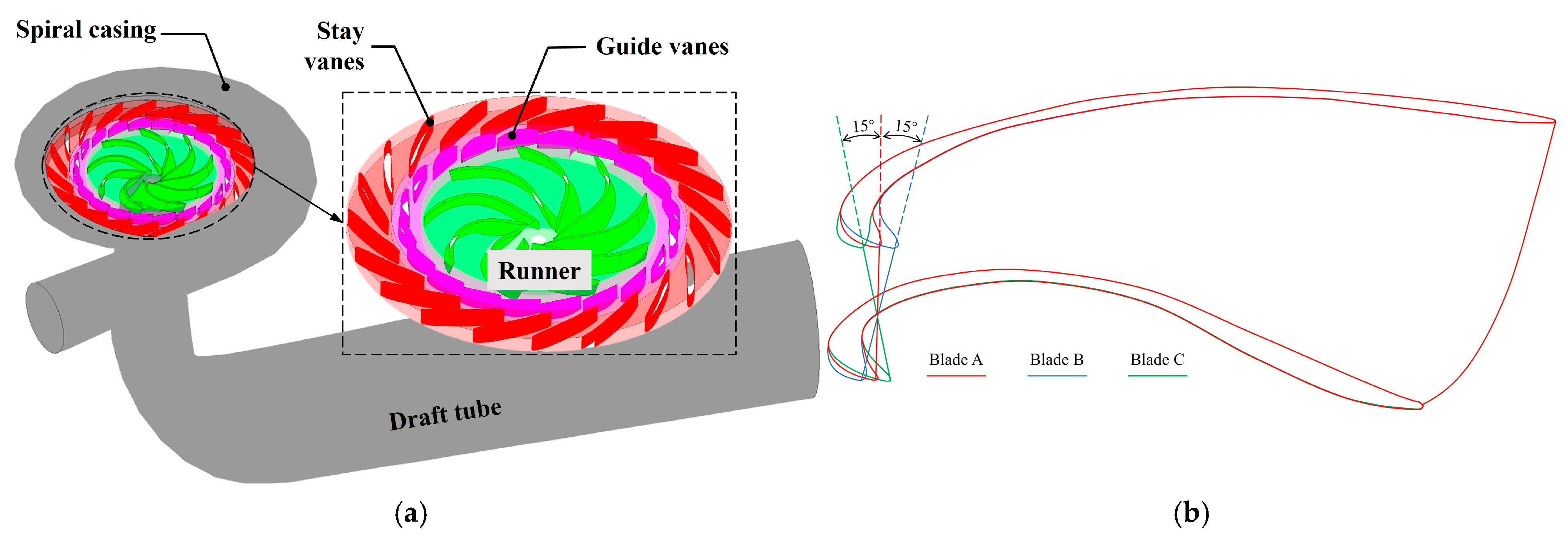
Figure 1. The pump-turbine model. (a) Three-dimensional model. (b) Schematic of the runner blades at different BLEAs.
Water 17 03184 g001
Figure 2. Pressure pulsation monitoring points. (a) Spiral casing to runner. (b) Runner to draft tube.
Water 17 03184 g002
Figure 3. Grid-independent check and method validation. (a) Variation of η and H with element number. (b) Validation of pressure pulsation.
Water 17 03184 g003
Figure 4. Final selected mesh.
Water 17 03184 g004
Figure 5. Relative efficiency in turbine mode and pump mode. (a) Turbine mode and (b) pump mode.
Water 17 03184 g005
Figure 6. Pressure distribution and streamline within the spiral casing and stay vanes. (a) 100% P r in turbine mode. (b) Rated head in pump mode.
Water 17 03184 g006
Figure 7. Pressure distribution and streamline within the guide vanes and runner. (a) 100% P r in turbine mode. (b) Rated head in pump mode.
Water 17 03184 g007aWater 17 03184 g007b
Figure 8. Pressure distribution and streamline within the draft tube. (a) 100% P r in turbine mode. (b) Rated head in pump mode.
Water 17 03184 g008
Figure 9. Time history and frequency spectra of pressure pulsation at 100% P r of turbine mode. (a) Time history. (b) Frequency spectra.
Water 17 03184 g009
Figure 10. Time history and frequency spectra of pressure pulsation at the rated head of pump mode. (a) Time history. (b) Frequency spectra.
Water 17 03184 g010
Figure 11. Comparison of pressure pulsation peak-to-peak values between three blade models. (a) SP. (b) GV. (c) RV. (d) DT. (e) Gap.
Water 17 03184 g011aWater 17 03184 g011b
Figure 12. Energy dissipation distribution in stay vanes to the runner at 100% P r of turbine mode.
Water 17 03184 g012
Figure 13. Energy dissipation distribution in the runner to stay vanes at the rated head of pump mode.
Water 17 03184 g013
Disclaimer/Publisher’s Note: The statements, opinions and data contained in all publications are solely those of the individual author(s) and contributor(s) and not of MDPI and/or the editor(s). MDPI and/or the editor(s) disclaim responsibility for any injury to people or property resulting from any ideas, methods, instructions or products referred to in the content.