1. Introduction
In mining engineering, roadways are necessary for transporting materials, ores, and workers, so their stability is critical for security and sustainable production [
1,
2]. Geological rock mass always contains different types of weak structural planes (WSPs) such as faults, cracks, and joints, and the existence of these structural planes destroys the integrity of the rock mass and greatly damages its stability [
3,
4,
5,
6]. With the increase in mining depth, increasingly complex engineering geological environments will be faced for resource exploitation, so the effect of WSPs on deformation failure in deep roadways needs to be further explored. Moreover, in coastal mines, deformation along WSPs may hydraulically connect fault networks with overlying aquifers or seawater, posing catastrophic water-inrush risks. Quantifying WSP-controlled failure zones is thus critical for predicting preferential flow paths.
In recent years, rock mechanics has made unprecedented progress in numerical simulation methods, and various new methods and models have emerged [
7,
8]. Due to their low cost and repeatability, these methods have become increasingly significant in solving practical engineering issues [
9,
10,
11]. Currently, numerical investigations into the mining-induced deformation failure of surrounding rock employ various simulation software, such as PFC (Particle Flow Code), UDEC (Universal Distinct Element Code), RFPA (Rock Failure Process Analysis), and FLAC (Fast Lagrangian Analysis of Continua). These tools are based on methods such as DEM (Discrete Element Method) and FEM (Finite Element Method) [
12,
13,
14]. Bahaaddini et al. used PFC to simulate the deformation and instability process of joint surrounding rock, and compared the results with previous physical tests, proving that PFC can accurately simulate the mechanical characteristics and instability mechanisms of discontinuous jointed rock mass [
15,
16,
17,
18]. Based on RFPA, Tang et al. conducted numerical analysis on the deformation and nonlinear progressive failure characteristics of a circular roadway in deep rock mass, and studied the displacement and acoustic emission characteristics of the roadway under mining stress [
19,
20,
21,
22,
23]. Shen et al. used UDEC to build a model of rocks containing two sets of vertical joints. By changing parameters such as joint spacing, boundary conditions, ground stress, and joint direction, the influence radius on the unloading zone of tunnel excavation was explored [
24]. Through an open source DEM code ESyS-Particle, Yan et al. studied the significant influence of joint geometry on the mechanical properties and failure behavior of rock models with discontinuous joints under uniaxial compression, revealing the microscopic energy evolution characteristics and progressive failure behavior of rock models with multi-joints under uniaxial compression [
25,
26,
27].
Based on previous research, this study proposes an FDEM (Finite–Discrete Element Method) by enhancing a contact force calculation method, introducing slip rate parameters, and incorporating an elastic–plastic failure criterion. Consequently, an improved algorithm suite is proposed, and a corresponding program named Y-Mat is developed using Matlab. Then, the deformation failure of roadway surrounding rock under the influence of WSPs is simulated and analyzed based on the program. Finally, the control effects of structural plane distance and dip angle on roadway deformation failure are explored, providing a reference for the stability analysis of roadways under the influence of WSPs.
2. Background
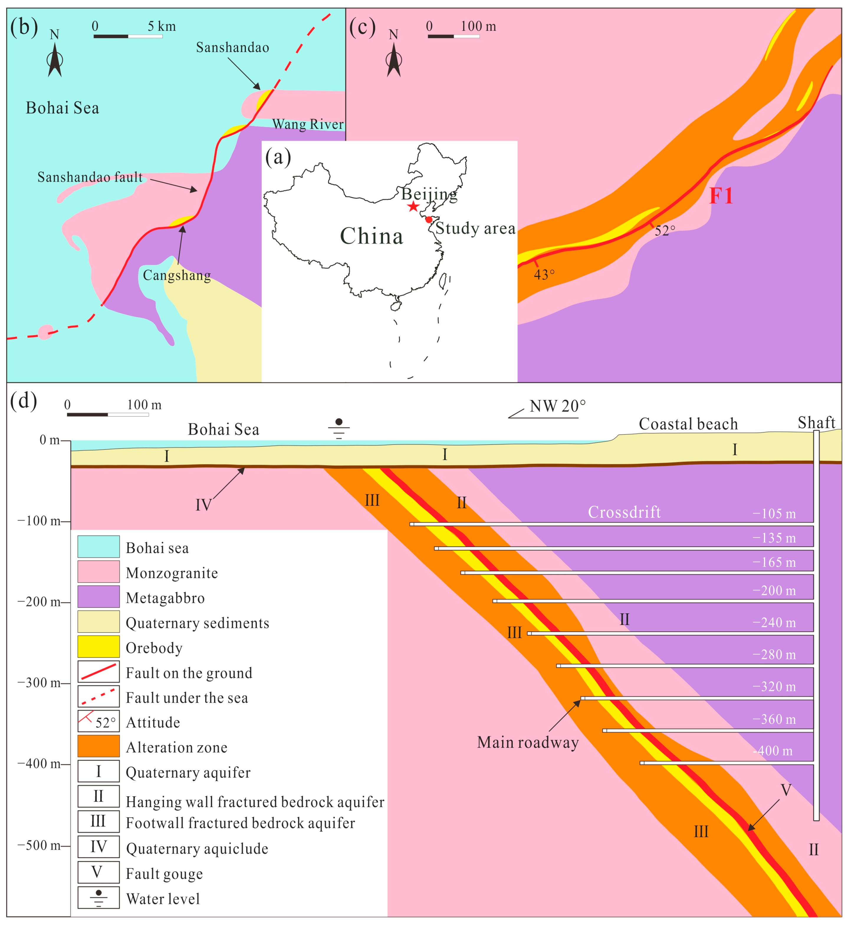
Sanshandao Gold Mine, located in Laizhou City, Yantai, Shandong Province, China, is the only remaining operational undersea mine in the country (
Figure 1a) [
28]. The geographical coordinates of the mining area lie between 37°24′01″ N and 37°24′44″ N, and between 119°56′54″ E and 119°57′20″ E. Situated on the coastal plain along the southern coast of the Bohai Sea, the region is surrounded by the sea to the north, west, and south, with land to the east. The mining area has a low-lying and relatively flat terrain, with an elevation ranging from 1.2 to 6 m above sea level, and features a continental climate in the northern warm temperate monsoon zone. Its surface water systems are well-developed: two seasonal rivers, the Wang River and the Zhuqiao River, traverse the entire study area. Both rivers are short in length, close to their sources, and have shallow water levels during autumn and winter (
Figure 1b).
The area is characterized by well-developed brittle fracture structures, with primary strikes in the northeast and northwest directions, forming the basic structural framework of the region. The northeast-trending fracture structures are represented by the Sanshandao fault zone (F1), which is the most developed first-order fracture structure in the area (
Figure 1c). This fault zone controls a series of large and super-large gold deposits, including those in Sanshandao, Cangshang, Xinli, Xiling, and the northern sea area of Sanshandao. In this region, the ore deposits are generally distributed below the main fracture surface (
Figure 1d).
As a common WSP in underground engineering, faults are a decisive factor controlling the deformation and stability of surrounding rock, which has a great influence on the characteristics of stress and displacement distribution. In the field investigation, it was found that when the roadway axis was parallel to the fault strike or intersected at a small angle and the roadway did not cross the fault zone, and the deformation and failure of the roadway were asymmetrical [
29].
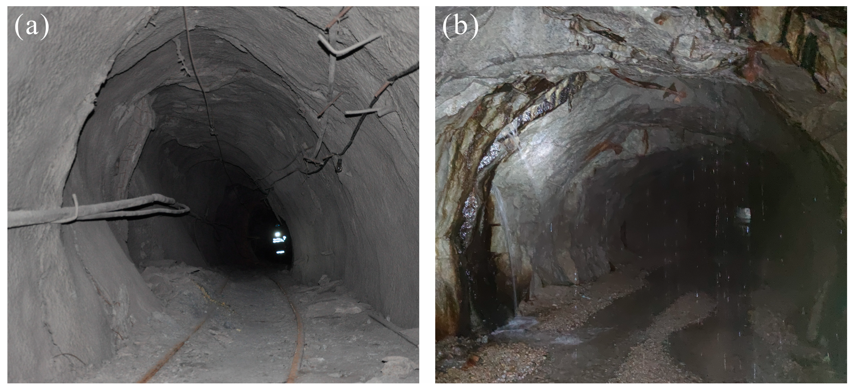
Figure 2 shows two roadways affected by faults. In
Figure 2a, the roadway was 220 m away from the fault. Concrete spraying was extruded from the south and west side, and the floor heave was obvious, with a variation of 6 cm in the first month. The roadway in
Figure 1b was 70 m away from the fault. It can be seen that the side wall was squeezed, and there was water seeping out. The variation in the roadway in the first month reached 23 cm, and the average daily variation was close to 1 cm [
28,
29].
Under excavation conditions, the roadway was biased when it was close to the fault. The side of the roadway close to the fault was more seriously damaged than the side far away from the fault. Moreover, when the roadway was close to the fault, the deformation of the surrounding rock was not only large but also occurred rapidly. The excavation destroyed the balanced state of the WSP, reduced the positive pressure of the plane, and decreased the shear strength. Under certain conditions, fault slip activation can be induced, posing a greater threat to the safety of roadway use. Therefore, the effect of WSPs on roadway deformation failure needs to be further explored.
3. Methodology
3.1. Y-Mat Program
The Finite–Discrete Element Method (FDEM), initially proposed by Munjiza et al., exhibits limitations in computational efficiency and the characterization of mechanical behaviors of rock [
30,
31]. Hence, a Y-Mat program is proposed in this study to address these shortcomings.
According to the contact force algorithm based on the penalty function originally proposed by Munjiza, the contact force is calculated according to the length of the invading edge and the potential of the center of the invading part, which simplifies the calculation process and greatly improves the calculation efficiency [
32].
Referring to the definition of static and dynamic loading in the laboratory, the concept of slip change rate in numerical simulation is proposed, and a calculation method for the contact tangential force considering static and dynamic friction and their mutual conversion is introduced [
33,
34].
Combined with the elastoplastic deformation of rock mass, and referring to the relevant theories in FLAC, the Mohr–Coulomb constitutive model and the maximum tensile stress criterion are introduced to correct the deformation force of the element after yield [
35].
Details regarding the specific optimization principles of the Y-Mat program are available in Reference [
36].
3.2. Numerical Model
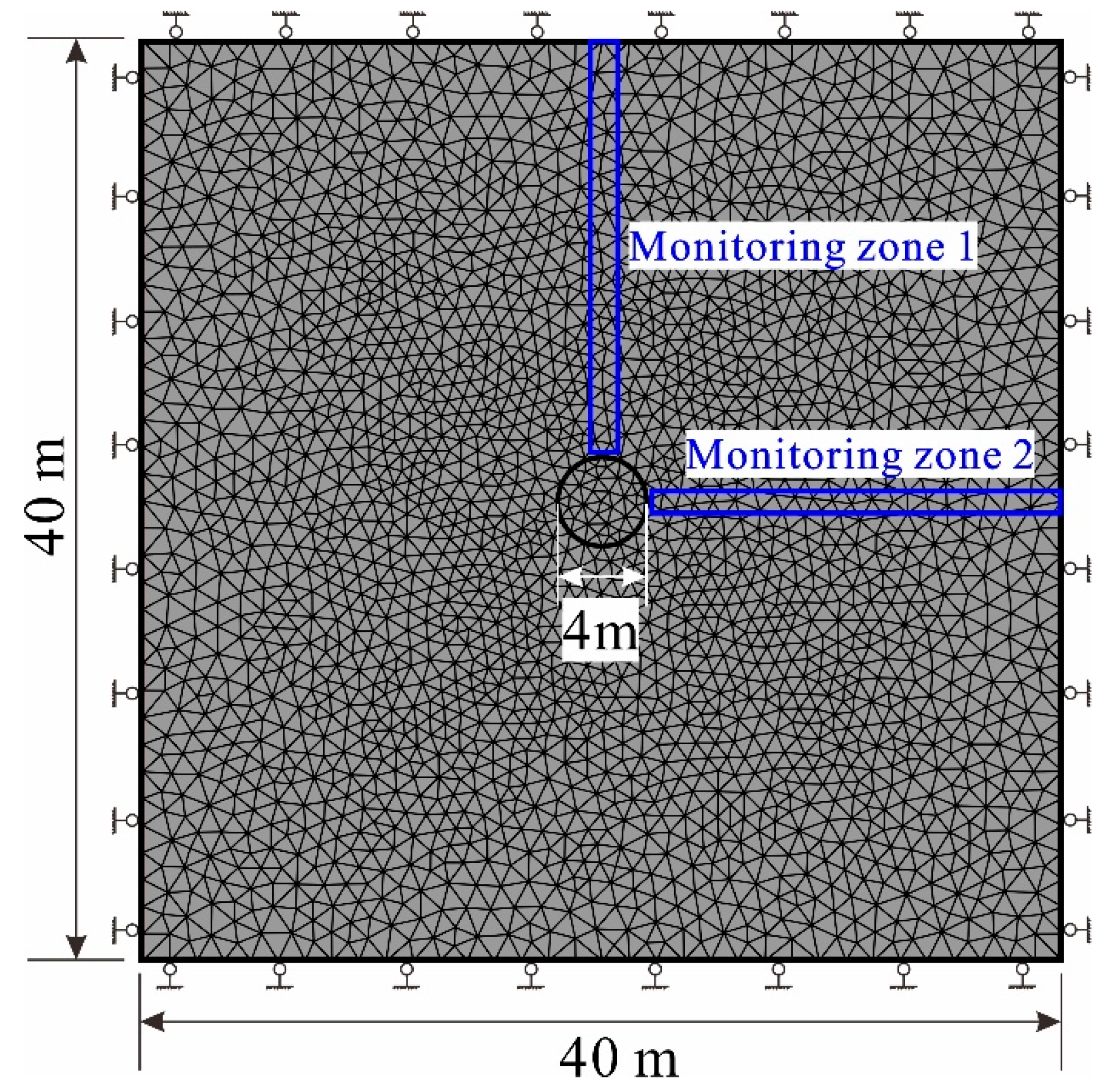
To verify the feasibility of the program in the tunnel excavation simulation, a numerical calculation model was established, as shown in
Figure 3. The size of the model was 40 m × 40 m, and the roadway was located at the center of the model with a radius of 2 m. The monitoring zones recorded the stress evolution process of the elements in the area. The physical and mechanical parameters measured in Sanshandao Gold Mine were adopted for the model unit, and the numerical model parameters used are shown in
Table 1 [
28,
29,
36]. The boundary conditions of the model were as follows: both sides limited the displacement in the horizontal direction, and the top and bottom boundaries limited the displacement in the vertical direction.
3.3. Verification of Model Reliability
The theoretical solution of the rock mechanics of secondary stress in the elastic zone of a circular roadway is as follows:
where
σr is radial stress;
σφ is tangential stress;
px is horizontal geostress;
py is vertical geostress;
φ is the angle between the line passing through the point and the center of the circle and the horizontal direction;
x is the distance from the point to the circle center; and
r is the radius.
According to Formula (1), the radial stress on the top and right sides of the roadway is 0, and the tangential stresses are 3 × (
px −
py) and 3 × (
py −
px), respectively. The boundary conditions, with a horizontal ground stress of 2 MPa and a vertical stress of 1 MPa, were entered into the formula and numerical model, respectively, and stress curves of the surrounding rock were drawn from the calculated results, as shown in
Figure 4.
The stress distribution curves demonstrate close alignment between the simulated and analytical results in the elastic zone, where both radial and tangential stresses follow theoretical predictions. Beyond the elastic limit, plastic behavior manifests as irregular stress fluctuations. Notably, stresses converge to far-field values at sufficient distance from the roadway, validating the optimized program’s physical realism. Quantitative analysis confirms the analytical solutions achieve exceptional accuracy (≤3% relative error, maximum deviation 2.5%) and precision (standard deviation <0.08 MPa, R2 ≈ 0.994) when benchmarked against numerical results. This agreement establishes the reliability of the Y-Mat model.
3.4. Scheme Design
To investigate the impact of the distance and angle of WSPs on roadway deformation failure, 8 simulation tests were designed, as shown in
Figure 5. The first 4 schemes studied the influence of the distance between the WSP and the center point of the roadway, with distances of 2 m, 4 m, 6 m, and 8 m. The last 4 schemes studied the influence of the WSP angle, with angles of 0°, 30°, 60°, and 90°. All calculations were performed using a plane strain model, with a horizontal stress of 10 MPa and a vertical stress of 5 MPa.
4. Results
4.1. Effect of Distance Between WSP and Roadway
The surrounding rock cracks and plastic zones of test 1–4 are presented in
Figure 6. The plastic zone is defined as the regions exceeding the Mohr–Coulomb yield criterion. As can be seen from the figure, the distance had a significant impact on the failure of surrounding rock. When the WSP was close to the roadway, the surrounding rock between the two was more serious, and shear cracks and tensile yields mainly occurred. When the fracture was far away from the roadway, the surrounding rock between them still had shear cracks and tensile yield, but the failure range in the horizontal direction decreased. The existence of the WSP affected the failure direction of the roadway. From the perspective of its failure mode, the roadway was prone to shear cracks, which was consistent with the simulation results of other scholars on roadway excavation [
37,
38,
39]. In addition, shear cracks constitute nearly 70% of all fractures in the plastic zone, while tensile cracks concentrate at the excavation boundary and contribute to spalling; both mechanisms are critical in the design of supports. The damage shapes were trapezoidal, and the local shape was related to the location and expansion direction of the crack. In relation to the failure direction, the fractures mainly spread in the vertical direction, opposite to the direction of the large deformation.
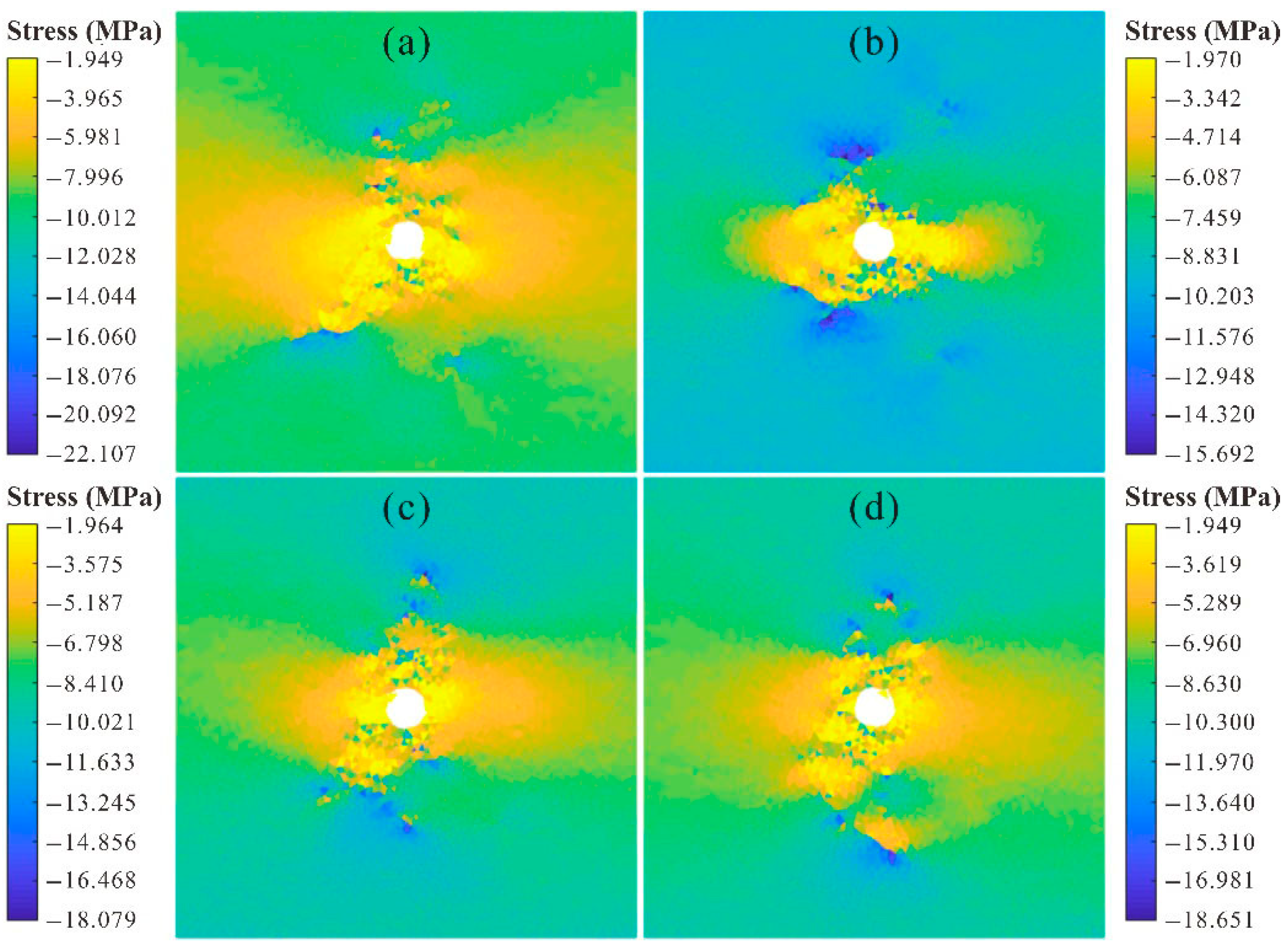
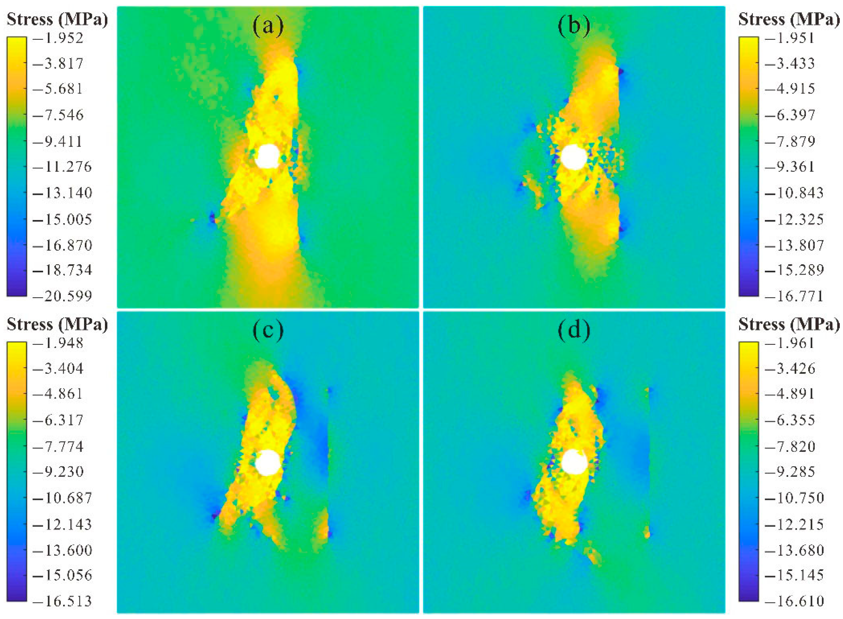
The horizontal and vertical stresses are illustrated in
Figure 7 and
Figure 8, respectively. As observed from these two figures, the distance had a significant influence on the horizontal and vertical stress fields of the roadway. The closer the distance was, the more obvious the surrounding rock stress drop. Because the strike of the crack was parallel to the vertical stress, the crack had a significant effect on the vertical stress field. In addition, shear cracks along WSPs create anisotropic permeability, potentially channeling groundwater toward roadways.
4.2. Effect of WSP Dipping Angle
The surrounding rock crack and plastic zone of test 5–8 are shown in
Figure 9. Fracture angle exerted a significant influence on the roadway failure, with its effects manifested in both the failure direction and location. The change in inclination angle caused the fracture direction to be deflected, and the damage to the surrounding rock between the roadway and the fracture was more serious. Under the condition of differential stress, the expansion direction of the crack was mainly upward and downward. Due to the existence of a horizontal crack, the upward expansion of the cracks was cut off, and the extension distance of the crack in this direction was shortened.
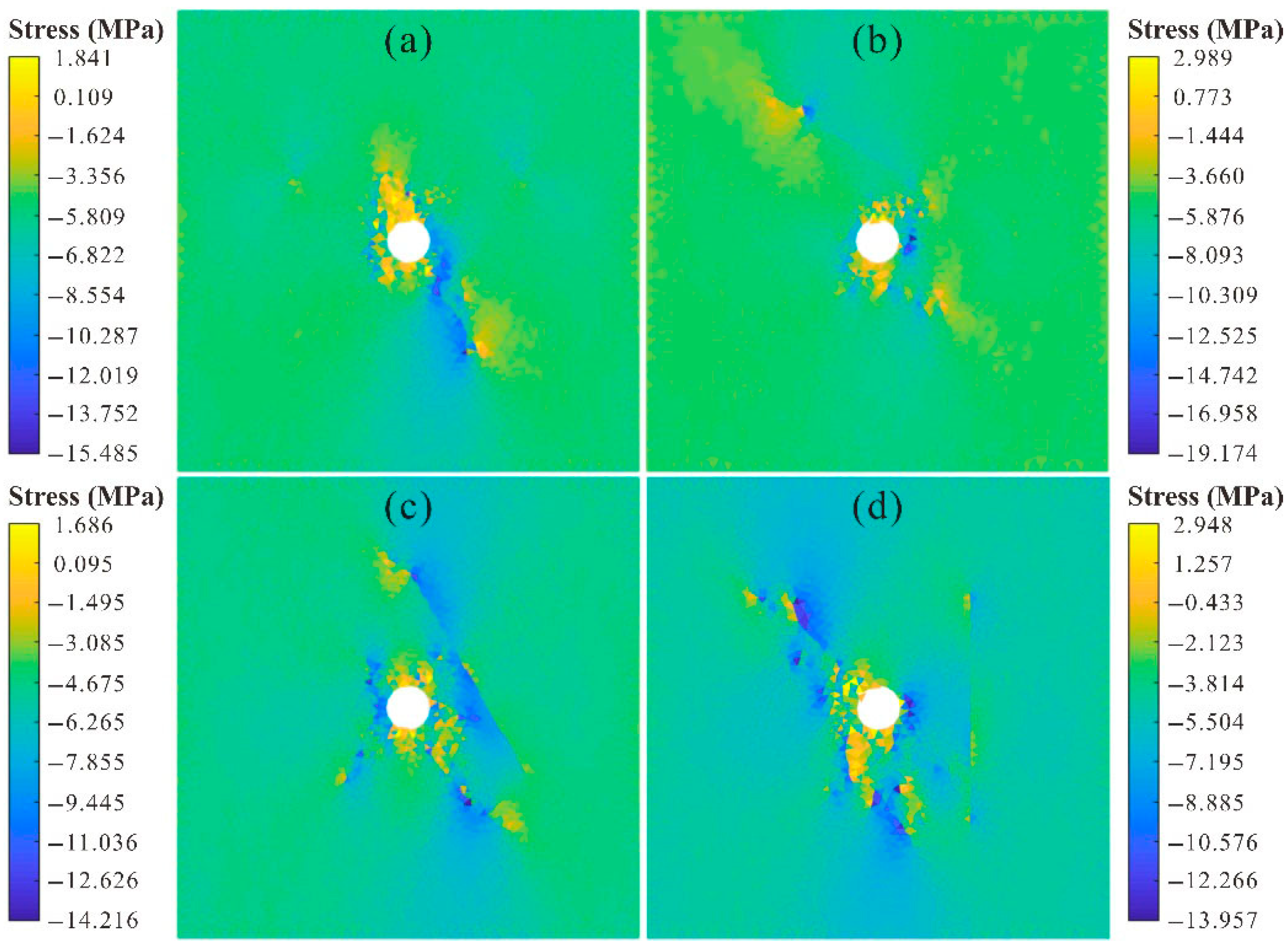
The horizontal and vertical stresses are shown in
Figure 10 and
Figure 11. The WSP angle had a significant influence on the roadway deformation failure. Variations in the fracture angle altered both the direction and shape of the stress reduction zone, accompanied by significant stress differentiation. Moreover, the degree of stress differentiation was closely related to the crack angle (the angle between the maximum principal stress and the composition of the crack). Moreover, angled WSPs deflect fractures toward vertical stress directions, increasing risks of intersecting overlying aquifers.
5. Discussion
In the process of mine construction, a large number of roadways need to be excavated and maintained; here, the resulting deformation failure of the surrounding rock is often controlled by the WSPs. The distribution and characteristics of the plane are the internal factors of the rock mass stability, and they determine the failure modes, scales, and characteristics.
The distribution characteristics of WSPs in the surrounding rock of underground caverns and the structural trace in the rock mass medium will affect the physical and mechanical behavior of the rock mass. The strength of these discontinuities is always low, and the deformation resistance and modulus are also several orders of magnitude lower than those of rock materials. Therefore, such rock mass will show strong heterogeneity, anisotropy, and discontinuity. The existence of WSP reduces the macroscopic strength of the rock mass obviously, and the roadway failure is mainly controlled by the strength of the WSP. That is, the deformation failure of the surrounding rock first occurs around the weak structural face with low strength when other conditions are similar. Additionally, under low confining pressure, cracks, slippage, and deformation occur around the WSP. The failure of the WSP will cause a change in the relationship between the WSP and the adjacent rock mass, which will aggravate the deformation failure of the surrounding rock mass in other parts of the roadway and generate permeable channels. In coastal mines, this process may connect faults to seawater via fractures, triggering water inrush when hydraulic gradients exceed critical thresholds.
When excavating near a WSP, the surrounding rock close to the plane is damaged more seriously. Due to the influence of WSPs, roadways often experience local rapid falls, whole collapse, bedding slips, and so on. If the axial direction of the roadway is consistent with the strike of the fault, it is easy for shear slip to occur along the fault surface and cause fault activation, resulting in collapse. It can be seen that the WSP has an important impact on the overall safety of the surrounding rock of the roadway. Fully understanding the effect of WSPs in underground engineering is significant for guiding the construction of underground engineering and preventing disasters.
6. Conclusions
- 1.
By introducing slip change rate and maximum static friction to solve the tangential contact force in the process of dynamic and static transformation, an elastoplastic failure criterion was adopted to describe the yield behavior of rock mass during deformation, and an optimized Y-Mat program was established. The mechanical response of surrounding rock after roadway excavation under differential stress was calculated, and the simulated stress results were compared with the corresponding analytical solutions to verify the rationality of the program.
- 2.
The farther the WSP was from the roadway, the less influence it had on the roadway. At the same time, the existence of the WSP changed the shape of the plastic zone, lengthening the failure zone along the fault direction. The WSP angle can change the shape and location of the failure zone of the surrounding rock, and it also leads to a deflection of the fracture direction. The surrounding rock between the roadway and the WSP is the most serious failure zone.
- 3.
The deformation failure of roadway surrounding rock first occurred at the weak structural face with low strength, caused by the WSP effect. Excavation reduced the normal stress and shear strength of the WSP in surrounding rock, resulting in relative slip and deformation. As time passed, the rock mass in other parts of the roadway also produced damage along the primary or new fracture surface, which intensified the roadway deformation failure and even caused a disaster.
- 4.
WSP-induced fractures serve as conduits for groundwater influx, especially in fault-proximal roadways or where crack angles align with hydraulic gradients. Mitigation strategies should prioritize sealing these pathways in water-rich mining environments.
Author Contributions
Data curation, G.L.; formal analysis, G.L. and J.G.; methodology, J.G. and G.L.; software, G.L. and J.G.; writing—original draft, J.G.; writing—review and editing, G.L. and F.M. All authors have read and agreed to the published version of the manuscript.
Funding
This research was supported by the National Science Foundation of China (Grant No. 42072305) and the Second Tibetan Plateau Scientific Expedition and Research Program (Grant No. 2019QZKK0904).
Data Availability Statement
All the relevant data are included in the paper.
Acknowledgments
The authors are grateful to the assigned editors and anonymous reviewers for their enthusiastic help and valuable comments, which have greatly improved this paper.
Conflicts of Interest
The authors declared that they have no conflicts of interest regarding this study. We declare that we do not have any commercial or associative interests that represent a conflict of interest in connection with the paper submitted.
References
- Li, G.; Ma, F.; Guo, J.; Zhao, H.; Liu, G. Study on deformation failure mechanism and support technology of deep soft rock roadway. Eng. Geol. 2020, 264, 105262. [Google Scholar] [CrossRef]
- Baghbanan, A.; Jing, L. Stress effects on permeability in a fractured rock mass with correlated fracture length and aperture. Int. J. Rock Mech. Min. Sci. 2008, 45, 1320–1334. [Google Scholar] [CrossRef]
- Li, G.; Ma, F.; Guo, J.; Zhao, H. Deformation Characteristics and Control Method of Kilometer-Depth Roadways in a Nickel Mine: A Case Study. Appl. Sci. 2020, 10, 3937. [Google Scholar] [CrossRef]
- Hoek, E.; Brown, E.T. Underground Excavations in Rock; CRC Press: Boca Raton, FL, USA, 1980. [Google Scholar]
- Li, G.; Ma, F.; Guo, J.; Zhao, H. Experimental research on deformation failure process of roadway tunnel in fractured rock mass induced by mining excavation. Environ. Earth Sci. 2022, 81, 243. [Google Scholar] [CrossRef]
- Jing, L. A review of techniques, advances and outstanding issues in numerical modelling for rock mechanics and rock engineering. Int. J. Rock Mech. Min. Sci. 2003, 40, 283–353. [Google Scholar] [CrossRef]
- Li, G.; Liu, S.; Ma, F.; Guo, J.; Hui, X. Numerical Study on the Mechanical Behavior of Hydraulic Fractures under Stress Disturbance, based on a Multi Pb-GBM Method. Acta Geol. Sin.-Engl. Ed. 2024, 98, 1659–1671. [Google Scholar] [CrossRef]
- Li, G.; Liu, S.; Lu, R.; Ma, F.; Guo, J. Experimental Study on Mechanical Properties and Failure Laws of Granite with Artificial Flaws under Coupled Static and Dynamic Loads. Materials 2022, 15, 6105. [Google Scholar] [CrossRef] [PubMed]
- Meng, B.; Jing, H.; Chen, K.; Su, H. Failure mechanism and stability control of a large section of very soft roadway surrounding rock shear slip. Int. J. Min. Sci. Technol. 2013, 23, 127–134. [Google Scholar] [CrossRef]
- Li, G.; Wan, Y.; Guo, J.; Ma, F.; Zhao, H.; Li, Z. A Case Study on Ground Subsidence and Backfill Deformation Induced by Multi-Stage Filling Mining in a Steeply Inclined Ore Body. Remote Sens. 2022, 14, 4555. [Google Scholar] [CrossRef]
- Li, G.; Ma, F.; Guo, J.; Zhao, H. Case Study of Roadway Deformation Failure Mechanisms: Field Investigation and Numerical Simulation. Energies 2021, 14, 1032. [Google Scholar] [CrossRef]
- Elmo, D.; Stead, D. An integrated numerical modelling–discrete fracture network approach applied to the characterisation of rock mass strength of naturally fractured pillars. Rock Mech. Rock Eng. 2010, 43, 3–19. [Google Scholar] [CrossRef]
- Li, G.; Ma, F.; Liu, G.; Zhao, H.; Guo, J. A Strain-Softening Constitutive Model of Heterogeneous Rock Mass Considering Statistical Damage and Its Application in Numerical Modeling of Deep Roadways. Sustainability 2019, 11, 2399. [Google Scholar] [CrossRef]
- Fukuda, D.; Mohammadnejad, M.; Liu, H.; Dehkhoda, S.; Chan, A.; Cho, S.; Min, G.; Han, H.; Kodama, J.; Fujii, Y. Development of a GPGPU-parallelized hybrid finite-discrete element method for modeling rock fracture. Int. J. Numer. Anal. Methods Geomech. 2019, 43, 1797–1824. [Google Scholar] [CrossRef]
- Bahaaddini, M.; Sharrock, G. Numerical investigation of the effect of joint geometrical parameters on the mechanical properties of a non-persistent jointed rock mass under uniaxial compression. Comput. Geotech. 2013, 49, 206–225. [Google Scholar] [CrossRef]
- Fan, X.P. Mechanical behavior of rock-like jointed blocks with multi-non-persistent joints under uniaxial loading: A particle mechanics approach. Eng. Geol. 2015, 38, 190–196. [Google Scholar] [CrossRef]
- Cheng, C.; Xin, C.; Shifei, Z. Multi-peak deformation behavior of jointed rock mass under uniaxial compression: Insight from particle flow modeling. Eng. Geol. 2016, 213, 25–45. [Google Scholar] [CrossRef]
- Yang, X.-X.; Jing, H.W.; Chen, K.F.; Yang, S.-Q. Failure behavior around a circular opening in a rock mass with non-persistent joints: A parallel-bond stress corrosion approach. J. Cent. South Univ. 2017, 24, 121–127. [Google Scholar] [CrossRef]
- Tang, C.A. Crack propagation and coalescence in brittle materials under compression. Eng. Fract. Mech. 1998, 61, 311–324. [Google Scholar] [CrossRef]
- Zhang, Z.; Tang, C.A.; Xu, T.; Zhai, X.X.; Duan, D.; Li, F. Modeling of effect of intermittent joint on circular roadway stability. Int. Symp. Min. Sci. Saf. Technol. 2007, 70, 436–441. [Google Scholar]
- Zhang, K.; Chen, Y.L.; Fan, W.H.; Liu, X.; Luan, H.; Xie, J. Influence of Intermittent Artificial Crack Density on Shear Fracturing and Fractal Behavior of Rock Bridges: Experimental and Numerical Studies. Rock Mech. Rock Eng. 2020, 53, 553–568. [Google Scholar] [CrossRef]
- Zhou, Z.H.; Chen, Z.H. Parallel offset crack interactions in rock under unloading conditions. Adv. Mater. Sci. Eng. 2019, 2019, 1–18. [Google Scholar] [CrossRef]
- Zhang, Y.C.; Jiang, Y.J.; Tang, X.J.; Chen, M.; Shi, X.-S. Cracking behavior and local stress characteristics around the opening surrounded by two intermittent joints: Experiment and numerical simulation. Comptes Rendus Mec. 2020, 348, 33–61. [Google Scholar] [CrossRef]
- Shen, B.; Baeton, N. The disturbed zone around tunnels in jointed rock Masses. Int. J. Rock Mech. Min. Sci. 1997, 34, 271–279. [Google Scholar] [CrossRef]
- Yan, Z.L.; Dai, F.; Liu, Y.; Feng, P. Experimental and numerical investigation on the mechanical properties and progressive failure mechanism of intermittent multi-jointed rock models under uniaxial compression. Arab. J. Geosci. 2019, 12, 61–67. [Google Scholar] [CrossRef]
- Guo, H.; Ooi, E.T.; Saputra, A.; Yang, Z.; Natarajan, S.; Song, C. A quadtree-polygon-based scaled boundary finite element method for image-based mesoscale fracture modelling in concrete. Eng. Fract. Mech. 2019, 211, 420–441. [Google Scholar] [CrossRef]
- Liu, H.Y.; Kang, Y.M.; Lin, P. Hybrid finite-Discrete element modeling of geomaterials fracture and fragment muck-piling. Int. J. Geotech. Eng. 2015, 9, 115–131. [Google Scholar] [CrossRef]
- Li, G.; Wang, Z.; Ma, F.; Guo, J.; Liu, J.; Song, Y. A Case Study on Deformation Failure Characteristics of Overlying Strata and Critical Mining Upper Limit in Submarine Mining. Water 2022, 14, 2465. [Google Scholar] [CrossRef]
- Li, G.; Liu, S.-Q.; Ma, F.-S.; Guo, J. Numerical research on fractured surrounding rock deformation and failure law caused by submarine mining. Water 2022, 14, 3171. [Google Scholar] [CrossRef]
- Lisjak, A.; Mahabadi, O.; He, L.; Tatone, B.; Kaifosh, P.; Haque, S.; Grasselli, G. Acceleration of a 2D/3D finite-discrete element code for geomechanical simulations using General Purpose GPU computing. Comput. Geotech. 2018, 100, 84–96. [Google Scholar] [CrossRef]
- Lisjak, A.; Tatone, B.S.; Mahabadi, O.K.; Grasselli, G.; Marschall, P.; Lanyon, G.W.; de la Vaissière, R.; Shao, H.; Leung, H.; Nussbaum, C. Hybrid finite-discrete element simulation of the EDZ formation and mechanical sealing process around a microtunnel in Opalinus Clay. Rock Mech. Rock Eng. 2016, 49, 1849–1873. [Google Scholar] [CrossRef]
- Munjiza, A.; Andrews, K.R.F. NBS contact detection algorithm for bodies of similar size. Int. J. Numer. Methods Eng. 1998, 43, 131–149. [Google Scholar] [CrossRef]
- Mahabadi, O.K.; Grasselli, G.; Munjiza, A. Y-GUI: A graphical user interface and pre-processor for the combined finite-discrete element code, Y2D, incorporating material heterogeneity. Comput. Geosci. 2010, 36, 241–252. [Google Scholar] [CrossRef]
- Mahabadi, O.; Kaifosh, P.; Marschall, P.; Vietor, T. Three-dimensional FDEM numerical simulation of failure processes observed in Opalinus Clay laboratory samples. J. Rock Mech. Geotech. Eng. 2014, 6, 591–606. [Google Scholar] [CrossRef]
- Itasca, F. Fast Lagrangian Analysis of Continua in 3 Dimensions; Online Manual; Itasca Consulting Group: Minneapolis, MN, USA, 2013. [Google Scholar]
- Liu, G.; Ma, F.; Zhang, M.; Guo, J.; Jia, J. Y-Mat: An improved hybridfinite-discrete element code for addressing geotechnical and geological engineering problems. Eng. Comput. 2021, 39, 1962–1983. [Google Scholar] [CrossRef]
- Barton, N. Physical and discrete element models of excavation and failure in jointed rock. In Assessment and Prevention of Failure Phenomena in Rock Engineering; Pasamehmetoğlu, A.G., Ed.; Turkish National Society for Rock Mechanics: Istanbul, Turkey; Rotterdam, The Netherlands, 1993; pp. 35–46. [Google Scholar]
- Blümling, P.; Bernier, F.; Lebon, P.; Martin, C.D. The excavation damaged zone in clay formations time-dependent behaviour and influence on performance assessment. Phys. Chem. Earth Parts A/B/C 2007, 32, 588–599. [Google Scholar] [CrossRef]
- Armand, G.; Leveau, F.; Nussbaum, C.; de La Vaissiere, R.; Noiret, A.; Jaeggi, D.; Landrein, P.; Righini, C. Geometry and properties of the excavation-induced fractures at the Meuse/Haute-Marne URL drifts. Rock Mech. Rock Eng. 2014, 47, 21–41. [Google Scholar] [CrossRef]
| Disclaimer/Publisher’s Note: The statements, opinions and data contained in all publications are solely those of the individual author(s) and contributor(s) and not of MDPI and/or the editor(s). MDPI and/or the editor(s) disclaim responsibility for any injury to people or property resulting from any ideas, methods, instructions or products referred to in the content. |
© 2025 by the authors. Licensee MDPI, Basel, Switzerland. This article is an open access article distributed under the terms and conditions of the Creative Commons Attribution (CC BY) license (https://creativecommons.org/licenses/by/4.0/).


