Article

Development of Antifouling Polyvinylidene Fluoride and Cellulose Acetate Nanocomposite Membranes for Wastewater Treatment Using a Membrane Bioreactor

1
Department of Technology, Faculty of Engineering Science and Technology, Hamdard University, Karachi 75210, Pakistan
2
Department of Energy and Environment Engineering, Dawood University of Engineering & Technology, Karachi 74800, Pakistan
3
Department of Environmental Sciences, Sindh Madressatul Islam University, Karachi 74000, Pakistan
4
Department of Civil & Environmental Engineering, University of Utah, Salt Lake City, UT 84112, USA
5
Benazir Bhutto Shaheed University of Technology and Skill Development Khairpur, Khairpur 66151, Pakistan
6
Department of Chemical Engineering, College of Engineering, King Khalid University, Abha 61413, Saudi Arabia
*
Author to whom correspondence should be addressed.
Water 2025, 17(12), 1767; https://doi.org/10.3390/w17121767
Submission received: 20 April 2025 / Revised: 7 June 2025 / Accepted: 10 June 2025 / Published: 12 June 2025

Abstract

:
Membrane technology has received great attention in the desalination and water treatment sectors over the last few decades. However, membrane fouling remains a critical issue that affects membrane performance, a phenomenon common in membrane bioreactors (MBRs). This major drawback can be overcome by the preparation of antifouling membranes using an electrospinning technique that generates a hydrophilic modification of membranes. In this study, nanocomposite polyvinylidene fluoride (PVDF) and cellulose acetate (CA) polymer was fabricated to mitigate membrane fouling. Surface and mechanical characterization of the electrospun membrane was performed to assess morphology, chemical composition, and hydrophilic/hydrophobic properties. Anti-fouling performance of the composite PVDF/CA membrane was evaluated versus a neat PVDF membrane through bench-scale experiments. The PVDF/CA nanofiber membrane displayed a more hydrophilic nature, demonstrated by a lower water contact angle (101° vs. 115°) and increased wastewater flux (190 L/m2·h. vs. 160 L/m2·h), although the composite membrane demonstrated lower tensile strength (2.0 ± 0.1 MPa vs. 1.7 ± 0.1 MPa). The new material demonstrated greater anti-fouling performance compared to the neat PVDF membrane. Results suggest that this nanofiber material shows promise as an enhanced antifouling membrane that can overcome membrane fouling limitations.

1. Introduction

Complex contaminant mixtures comprised of concentrated organic matter, inorganic salts, microorganisms, and other constituents necessitate enhanced water treatment methods. Established technologies to enhance water purification, such as distillation, flocculation, and advanced oxidation processes (AOPs), often inadequately treat complex solutions and/or incur high equipment, operation and energy costs [1]. Membrane separation technology has wide application in wastewater treatment due to its cost-effectiveness, ease of operation, and high separation efficiency [2]. Electrospinning nanofiber membranes have higher interconnected pores, high porosity, narrow pore size distribution, and possibilities of membrane modifications; due to this, they could overcome the conventional membranes [3]. State-of-the-art membrane systems, such as membrane bioreactors (MBRs), can help play a role in fostering a more sustainable water purification paradigm by presenting robust, environmentally friendly, energy-efficient treatment options.
Membrane technology faces several challenges that reduce cost-effectiveness and operational efficiency, such as fouling caused by the accumulation of organic matter, biofilm and inorganic scaling [4,5]. Fouling not only interferes with ion transport through membranes but also requires higher operating pressure and voltage [6]. Colloids, sludge flocs, extracellular polymeric substances (EPSs), and soluble microbial products (SMPs) that adhere to the membrane surface during MBR operation impede the optimization of MBR operating parameters [7].
Higher viscosity feed water allows greater contaminant accumulation on the membrane surface [8]. Meanwhile, microbial activity has been reported to cause more than 45% of membrane fouling during wastewater treatment [9]. Exocellular polymeric substances (EPSs) and soluble microbial products (SMPs) are released by micro-organisms; comprised primarily of proteins, polysaccharides, and humic substances, these constituents represent key foulant agents [10,11,12]. These complex organic compounds have been shown to induce membrane pore blockage, while high molecular weight EPSs can form suspended solid particles that also contribute to cake fouling [10]. The hydrophobic functional groups inherent to these substances have a propensity to attach to hydrophobic membranes and promote fouling [13]. The strong protein adsorption to membranes makes these contaminants difficult to remove [14]. Moreover, this attachment stimulates biofilm growth, comprised of a mixture of bacterial cells in an EPS matrix that contains proteins, nucleic acids, and polysaccharides [15].
Several beneficial membrane materials limit biofouling impacts. Among these, polyvinylidene fluoride (PVDF), a semi-crystalline polymer, is used for filtration in wastewater treatment due to its chemical resistance and thermal stability in the presence of acids and alkalis, high hydrophobicity, and excellent mechanical strength [16]. The amorphous phase of this polymer accommodates the desired flexibility needed in a variety of applications, while the crystalline phase provides thermal stability similar to that inherent in other polymers [17]. These properties, plus their compatibility with biological substances, make it an attractive option in microfiltration [18,19], ultrafiltration [20,21], and membrane distillation [22,23]. A piezoelectric, hydrophobic PVDF membrane, exhibiting excellent chemical and mechanical strength, can thus be used as a composite material for various environmental applications [24].
Although PVDF provides a beneficial material for membrane separation purposes in MBRs, a major drawback is the hydrophobicity of these membranes, predisposing them to fouling by proteins and pollutants that display hydrophobic properties [25]. These hydrophobic membranes suffer from rapid membrane fouling and flux decline. A hydrophilic membrane overcomes fouling problems because it can form a hydration layer on the membrane surface and reduce pollutant adhesion [25].
Functional nanofibers offer an advantageous material with strong performance characteristics due to uniform nanoparticle distribution. The electrospinning device, which consists of a copper porous spinneret and multiple air inlets, can achieve high yields of these materials [26]. Fouling of hydrophobic materials can be reduced by blending hydrophilic materials with the original membrane material in the form of nanofibers using electrospinning technology [27]. Surface hydroxyl (–OH) groups are abundant on cellulose fibers, and they form hydrogen bonds with water molecules, allowing water to spread across the surface. By nature, cellulose is a hydrophilic and hygroscopic substance that can absorb water. Despite its intrinsic hydrophilicity, cellulose offers unrivalled benefits as a superhydrophobic material substrate [28]. Cellulose acetate (CA) membranes are widely used for various separation applications due to such advantageous characteristics as low price, moderate chlorine resistance, good biocompatibility, and hydrophilicity [29]. The blending of CA as a major matrix with PVDF to fabricate a completely hydrophilic membrane with suitable mechanical properties for RO application is considered the first investigation [30].
Electrospinning has gained considerable interest due to its ability to produce a wide diversity of nanofiber materials that can be designed to have porous structures with excellent oil/water separation efficiency [31,32]. Nanofiber membranes developed through electrospinning exhibit high surface area, light weight, mechanical strength, good resistance, strong molecular orientation along the fiber axis, high length-to-diameter ratio and enhanced porosity [33,34]. The method of modifying the mechanical characteristics of core/shell composite electrospinning fibers by varying the core diameter may offer additional benefits by extending this approach to different core/shell material systems [35]. These advantages and potential for modification lend these nanofiber materials to fields such as health care, energy, environmental engineering, and defense.
Oil/water separation and stress-strain tests revealed that a composite PVDF/CA/PS material produced using electrospinning exhibited excellent mechanical strength, high oil-water flux, good mechanical strength, and good separation efficiency [36]. Such materials can be used in membrane bioreactors, which are a cost-effective and efficient technology for wastewater treatment that combines bioreactors with membrane technology [37]. Treating wastewater using membranes lowers environmental hazards like groundwater contamination and eutrophication [38].
The research presented here aims to utilize electrospinning technologies to develop a membrane with physicochemical properties that mitigate fouling in membrane bioreactors (MBRs). To enhance the hydrophilicity of a polyvinylidene fluoride (PVDF) matrix, cellulose acetate (CA) was incorporated into the PVDF matrix. This led to the creation of an electrospinning PVDF/CA nanofiber membrane. A pristine, unaltered “neat” PVDF membrane was also produced for comparative analysis. This technique for modifying membrane properties was investigated to enhance overall membrane performance, with the expectation that a hydrophilic composite PVDF/CA material could be produced.

2. Materials and Methods

A cellulose acetate (CA) polymer (m.w. 30 kDa) and a polyvinylidene fluoride (PVDF) polymer (m.w. 534,000 Daltons) were purchased from Merck KGaA (Darmstadt, Germany) and N-N-dimethylformamide (DMF) and acetone as a solvent were purchased from Aldrich Sigma (St. Louis, MO, USA).

2.1. Electrospun Nanofiber Membrane

Sixteen percent PVDF polymer (wt/vol) was dissolved in a binary solvent of acetone and DMF at a 1:1 ratio, as reported in the literature [39]. The mixture was stirred vigorously for 5 h at 80 °C. A 5-mL plastic syringe was used to introduce the PVDF solution into the electrospinner. A pure copper wire was attached to the positive terminal and suspended in the pristine PVDF solution while a ground collector was connected to the negative terminal. An 11 cm distance was maintained as a 20 kV voltage was applied. The neat PVDF sheet was deposited on a rotating collector up to the desired thickness. The electrospinning parameters are given in Table 1.
Similarly, an 18% CA solution was dissolved in a DMF-acetone solvent (1:2) at room temperature. The PVDF/CA mixture was blended by a stirrer at an 80:20 ratio and subsequently electrospun using the same procedure as stated above. The electrospinning solution parameters are found in Table 2.

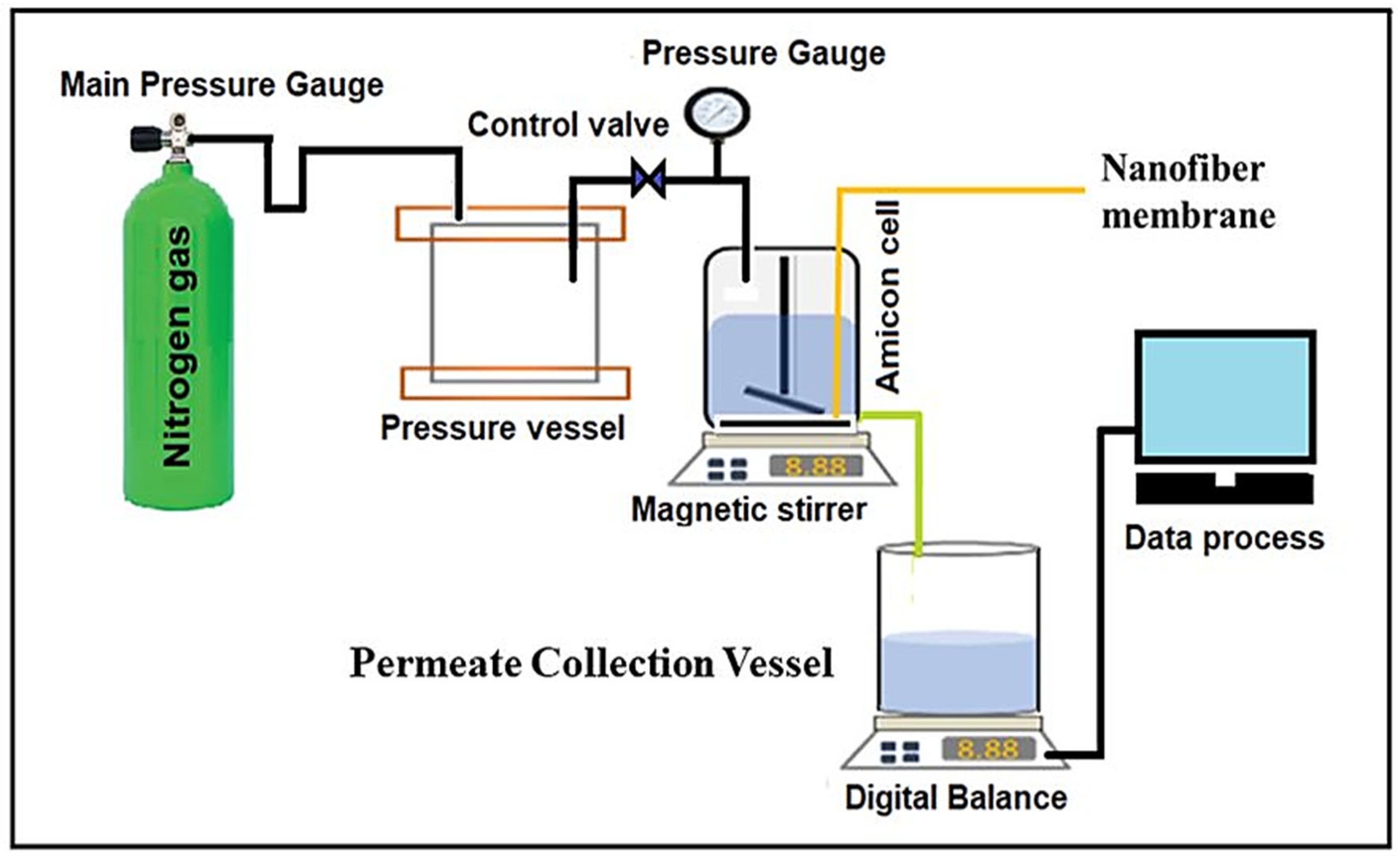
2.2. Dead-End Filtration Experimental Set-Up

Antifouling performance determination of the neat PVDF and composite PVDF/CA nanofiber membranes was conducted using a dead-end filtration experiment using an Amicon Cell 200 mL (Amicon, Miami, FL, USA) experimental setup (Figure 1). The antifouling performance and the filtration tests were performed on a 28.3 cm2 piece of membrane that was sized according to the vessel dimensions. Before each experiment, the membranes were soaked in milli-Q water to remove any chemicals. Both membranes were operated under a constant 10 psi pressure in a beaker where the filtrate was collected and placed on a digital balance. Relevant data were collected every 15 s.
The water flux across each membrane was evaluated using an experimental cell with a dead-end mode. To remove any potential chemical contamination, the membranes were pressurized at 0.2 MPa for an hour, after which a clean water filtration test was performed, and the permeation flux was calculated using Equation (1) [40,41].
J = V / A × T
where J is total flux (m2 h)−1, V is permeate volume (L), A is area (m2), and T is time (h). Nitrogen gas was injected into the Amicon cell during the dead-end filtration test to determine the filtration resistance of clogged membranes. Due to the constant pressure, the membranes fouled, and the permeate declined. During the filtration process, there was almost a 100% rejection of total suspended solids in both the neat and composite PVDF nanofiber membranes. Equations (2)–(4) were used to form a model series, and resistance was applied to determine the filtration resistance [42].
J p / μ R d V p /   A d t
R = R m + R c
R c = m α
where μ is permeate viscosity, p is membrane pressure, R is total hydraulic resistance (m−1), m is accumulated mass on the membrane surface, J is the water flux, A is membrane surface area, and Rc is the total cake resistance.
A rearrangement of Equations (2)–(4) yields [43]:
t / V p   μ R m A P + μ C 0 α   / 2 A 2 P   × V p
where C0 is the initial solute concentration and T is the total time that occurred during the process.

2.3. Nanofiber Characterization

The morphology of neat and composite PVDF/CA nanofibers was determined through scanning electron microscopy (SEM). To increase resolution, the membranes were gold-plated by applying a 10 kV voltage at a 5 mm working distance, which yielded a quality SEM image. The average membrane thickness was determined using a digital micrometer screw gauge. To measure the fiber diameter of at least 50 fibers, Image J 1.54d software was used. The apparent porosity and density of the membrane were calculated using Equations (6) and (7) [42].
A p p a r e n t   d e n s i t y   o f   f i b e r s g / c m 3 = M a t   m a s s   i n g M a t t h i c k n e s s c m × M a t   a r e a   i n c m 3
P o r o s i t y   o f   M a t = 1 ( M a t   a p p a r e n t   d e n s i t y ( g / c m 3 ) × 100 % / M i x t u r e   d e n s i t y ( g / c m 2 )
The contact angle of the membrane surface was calculated using the DataPhysics OCA 15EC (DataPhysics Instruments, Filderstadt, Germany) by applying 3 µm of milli-Q water at room temperature. After applying the droplet on the membrane surface, the contact angle measurements were carried out immediately. The experiments were replicated six times, and average PVDF and PVDF composite membrane values were calculated. Higher contact angles denote more hydrophobicity, and lower contact angles indicate greater hydrophilicity.
The molecular structure of the neat and composite PVDF/CA nanofiber membranes was determined using Fourier Transform infrared spectroscopy (FTIR). The depth of penetration was approximately 0.44–0.95 µm using a 45° incident angle of light on an ATR element. It is well known that infrared spectroscopy is a useful technique to elucidate the structure, composition, and conformation of polymeric chains, but sufficient information about polymeric membrane structure is not achieved through this technique. Energy dispersive spectroscopy (EDS) was used to determine the nanofiber chemical structure of the membranes. The stress-strain curve indicated the mechanical properties of the composite PVDF/CA and neat PVDF membranes. The strip test method was used to conduct the tensile strength tests with a tensile tester that adhered to ASTM standard D-5035-06 [39]. Membrane subsamples were 4 cm by 2 cm and were 100–120 µm thick, as determined by a digital micrometer. The load cell test’s maximum extension was 100 cN. During testing, the maximum strain was determined to be the elongation at the break point.

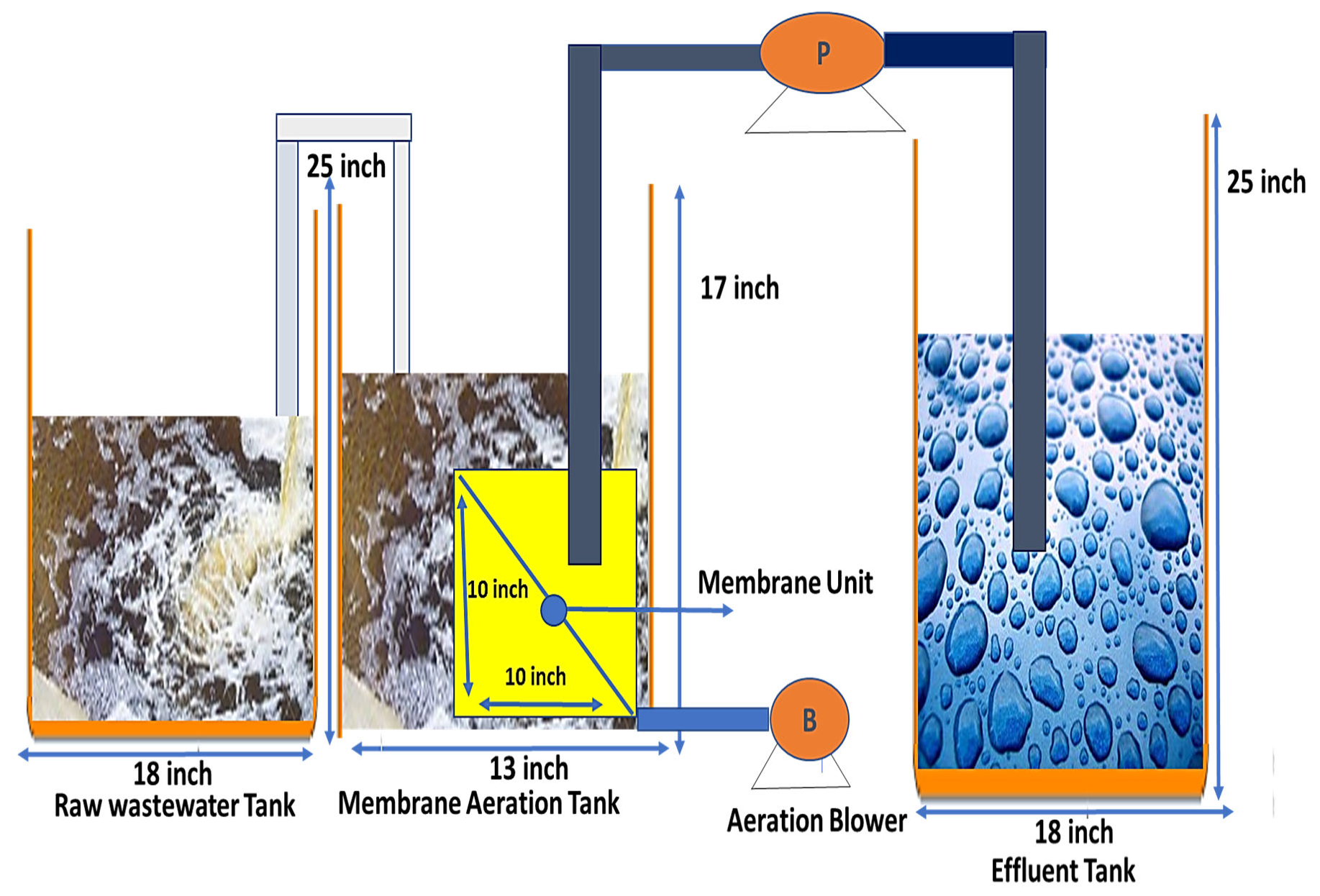
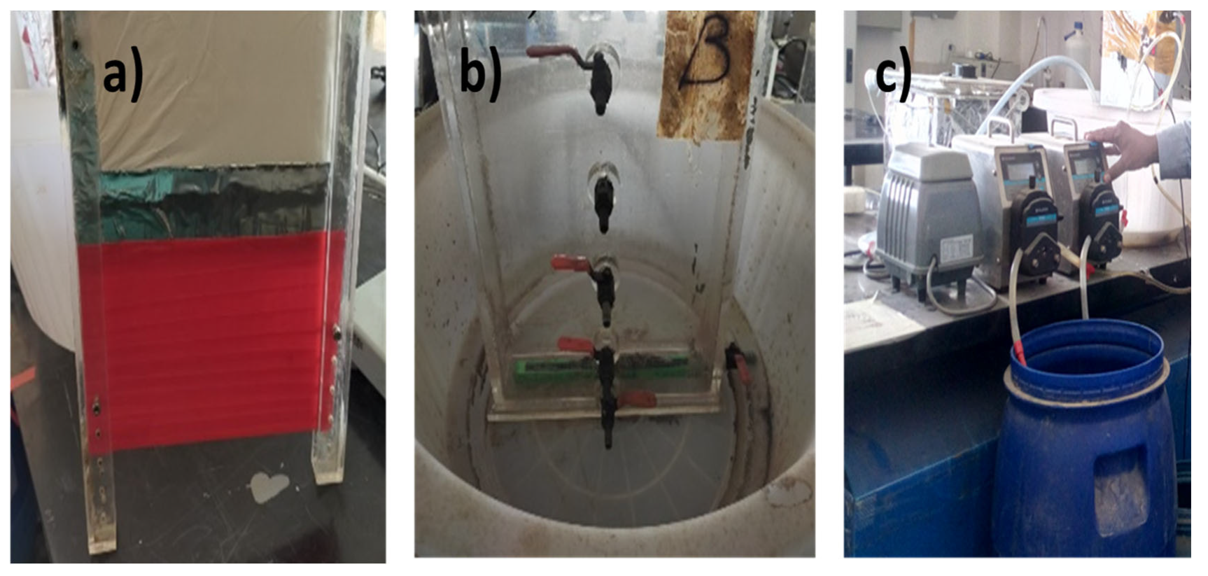
2.4. Submerged Membrane Use in Bioreactors for Wastewater Treatment

A lab-scale submerged membrane bioreactor was used to simulate wastewater treatment. The composite PVDF/CA and neat PVDF nanofiber membranes (25.4 × 25.4 cm) were fitted in the submerged membrane bioreactor as shown in Figure 2. The diffuser was used to produce compressed air in the reactor. Due to the hydrostatic pressure, the water was forced across the membrane. To prevent overflow of the reactor, an auto-leveller was installed. Activated sludge from a wastewater treatment plant was used to inoculate the reactor. The operating parameters of the membrane bioreactor are shown in Table 3. The wastewater was added to the reactor, having a pH of 8.3 ± 0.28, total suspended solids (TSSs) of 78 ± 1.88 mg/L, turbidity of 37 ± 1.2 NTU, and chemical oxygen demand (COD) of 651 ± 22 mg/L (Table 4).

3. Results and Discussion

3.1. Surface Morphology of the Nanofiber Membranes

Scanning electron microscope (SEM) images provided insight into the surface morphology of the neat and composite PVDF/CA nanofiber membranes (Figure 3). SEM analysis indicated that the blending of CA into the PVDF increased nanofiber roughness (Figure 3d–f), compared to the uniform and bead-free nanofibers of the neat PVDF membrane (Figure 3a–c). Correspondingly, the CA additions increased the nanofiber diameter, as represented by the accompanying histograms (Figure 3g,h).
Table 5 displays physical properties associated with the two membrane types. The average diameter of the composite PVDF/CA nanofiber was substantially larger than the neat PVDF nanofiber. The larger diameter can be attributed to the higher solution viscosity resulting from the CA amendments [43]. Correspondingly, the composite membrane exhibited a high porosity (91%) due to the well-developed interstices [44]. When the fiber structure becomes more porous, it likewise increases the surface area. Moreover, the fully interconnected porous structure of the composite PVDF/CA membrane allows for increased penetration and a greater water flux. These changes in the nanofiber structure are favorable for various applications, such as ultrafiltration [41,45], absorption [46], and ion-exchange [47].

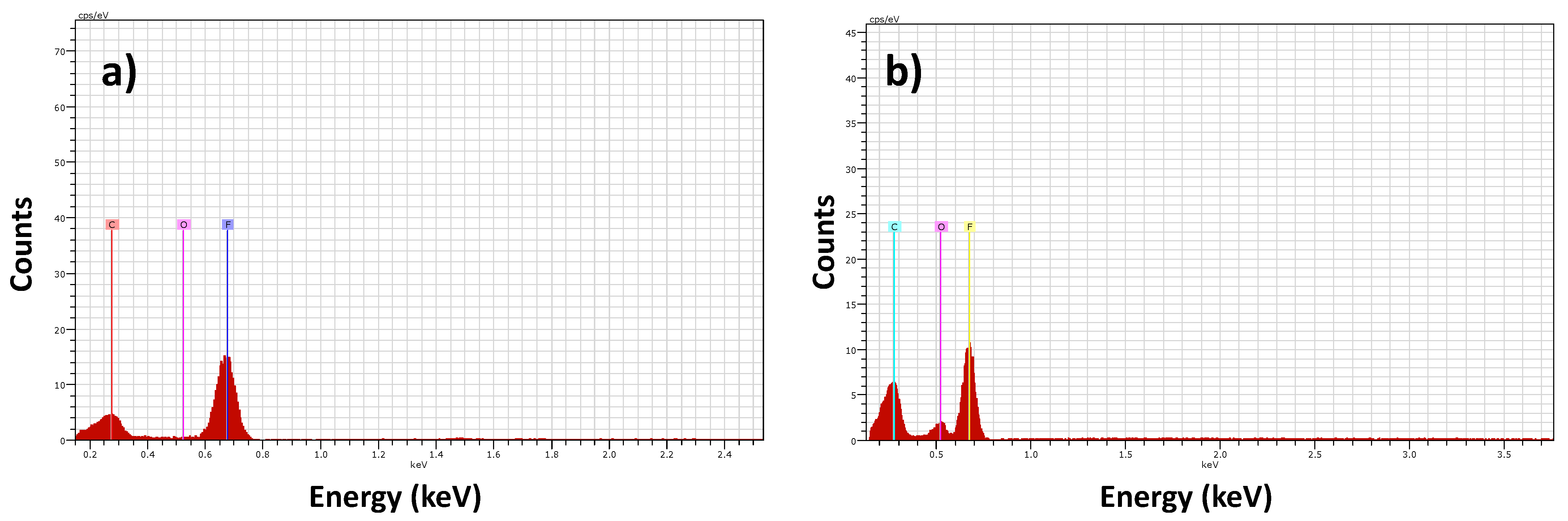
3.2. Energy Dispersive Spectroscopy (EDS)

Energy dispersive spectroscopy (EDS) results are displayed in Figure 4 and Table 6. The atomic percentage of oxygen in the composite PVDF/CA membrane increased from 4.3% to 10.4%, while the atomic percentage of fluorine decreased dramatically from 70.1% to 59.7%. These findings indicate that when cellulose acetate is mixed with PVDF membrane, it changes the structure of the membrane. The larger oxygen concentration will increase the membrane’s hydrophilicity, which will be further strengthened by the lower water contact angle described in the section below.

3.3. FTIR Spectra of the Nanofiber Membranes

The Fourier transform infrared radiation (FTIR) of the composite PVDF/CA and neat PVDF membranes is shown in Figure 5. The bands that appear at 642 cm−1, to indicate asymmetric stretching, while the peaks found at 869 cm−1 and 1067 cm−1 are moieties out-of-plane and in-plane moieties of the membrane. At 1169 cm−1 and 1400 cm−1, the two absorption bands observed for the PVDF nanofibers are generated by CF2 groups [48,49,50]. The band at 1725 cm−1 in the composite membrane results from symmetrical stretching of the C=O carbonyl (likely in the acetyl functional group), while that at 1221cm−1 is caused by the stretching of the ester bond and the peak at 1368 cm−1 results from C-H deformation. These phenomena develop from the presence of CA, which is readily incorporated into the PVDF matrix. The spectra shown in Figure 5 indicate that CA is successfully incorporated into the PVDF membrane.

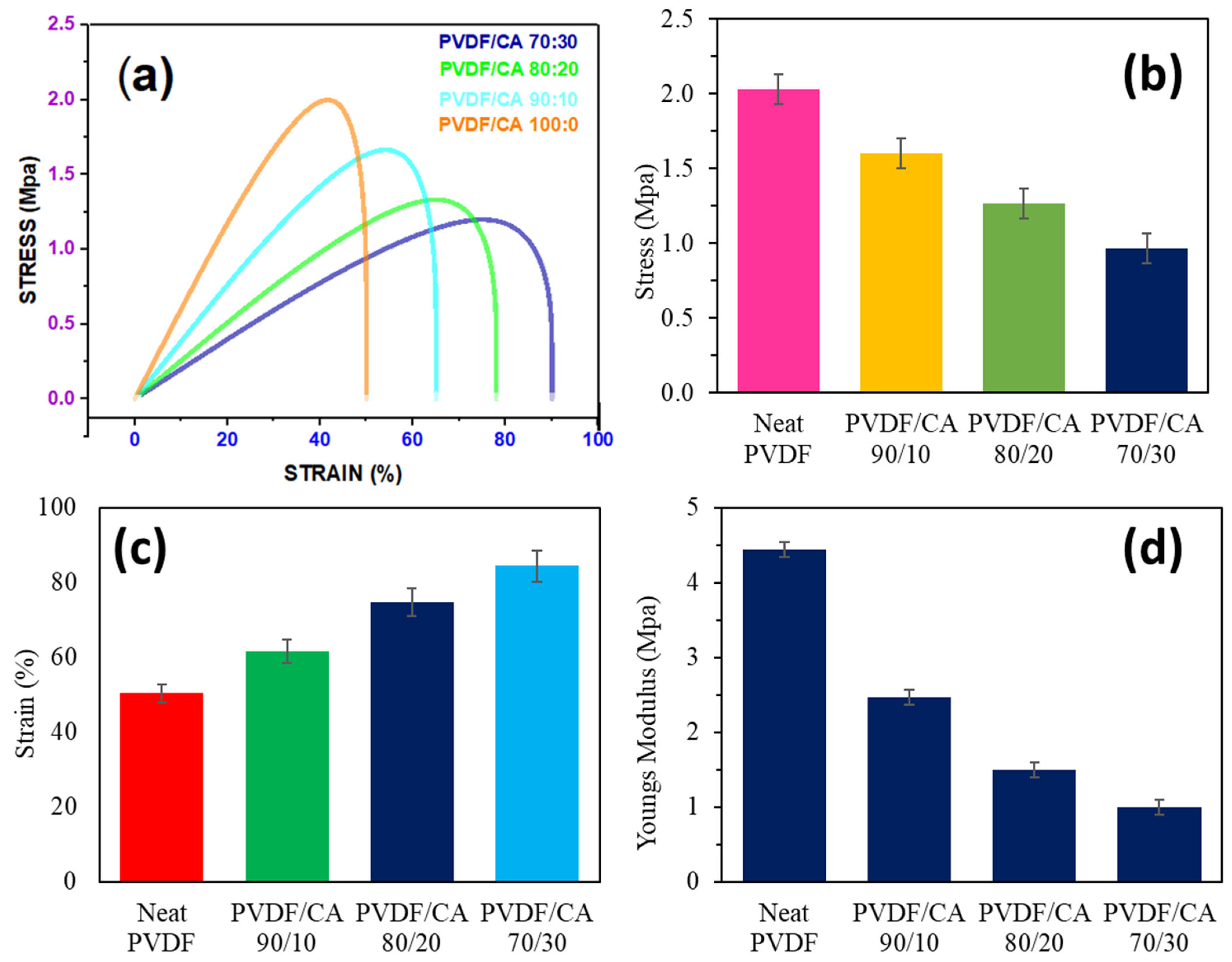
3.4. Membrane Tensile Strength

The tensile strengths of the composite PVDF/CA and neat PVDF nanofibers were assessed with a universal tensile tester apparatus, using thicknesses ranging from 80 to 100 mm (Figure 6). The neat PVDF membrane’s ultimate tensile strength was 2.0 ± 0.1 MPa and its elongation break was 45%. The composite PVDF/CA nanofibers were examined at various cellulose acetate ratios, which demonstrated a decrease in Young’s modulus when increasing the cellulose acetate concentration, an increase in elongation at break, and a reduction in tensile strength. A PVDF/CA ratio of 70:30, 80:20, and 90:10 yielded a tensile strength of 1.3 ± 0.1 MPa, 1.4 ± 0.1 MPa, and 1.7 ± 0.1 MPa, respectively. Correspondingly, the elongation break values of 85 ± 1%, 77 ± 1%, and 62 ± 1% and Young’s modulus of 0.8 ± 0.1, 1.4 ± 0.1, and 2.0 ± 0.2, were measured, respectively.
The neat PVDF nanofibers had smaller average diameters (530 ± 60 nm) and better crystalline and molecular orientations than the composite membrane’s fibers, which yield stronger mechanical properties [44,49]. The higher tensile strength of the neat PVDF was a result of the lower nanofiber diameter, but the tensile strength of the composite membrane was lower due to an increase in nanofiber diameter. The general relationship between strength and diameter lends validity to this assumption, according to Equation (8):
Stress   ( Strength ) = Load   ( N ) / Area   ( π r 2 )
Thus, neat PVDF nanofibers with a diameter of 570 nm exhibit higher tensile strength than those found for the PVDF/CA membrane.

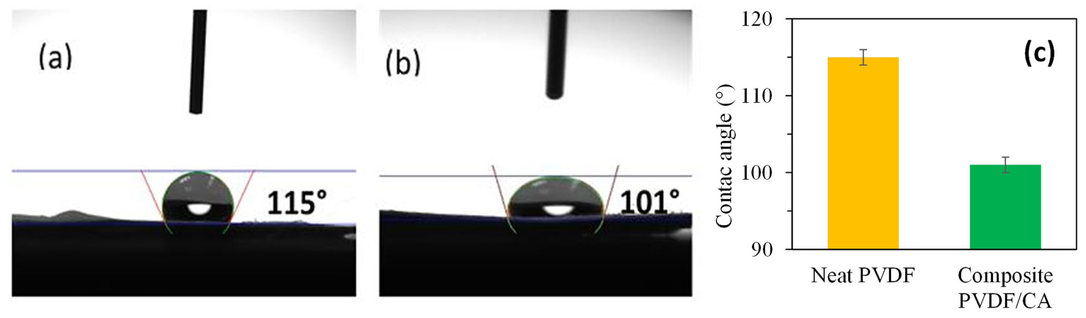
3.5. Membrane Hydrophobicity/Hydrophilicity

Membrane hydrophilicity and hydrophobicity can be inferred from contact angle measurements. The contact angles of the neat PVDF and composite PVDF/CA membranes were 115° and 101°, respectively (Figure 7). These results indicate that the composite PVDF-CA membrane exhibits greater hydrophilicity than the neat membrane. The water contact angle of the composite PVDF/CA membrane significantly decreased by the incorporation of CA into the PVDF matrix. It is well known that membrane hydrophilicity, wettability, and pore size can greatly affect the contact angle of the membrane [50]. When the water drops and encounters the composite PVDF/CA membrane, the water instantly spreads along the surface due to hydrogen bonds and electrostatic interactions. The presence of CA, having an inherent wettability, forms a micro-porous membrane surface when incorporated into the PVDF membrane that facilitates water drop penetration into the membrane matrix. The enhanced hydrophilicity will benefit the fouling resistance of the composite PVDF/CA membrane.

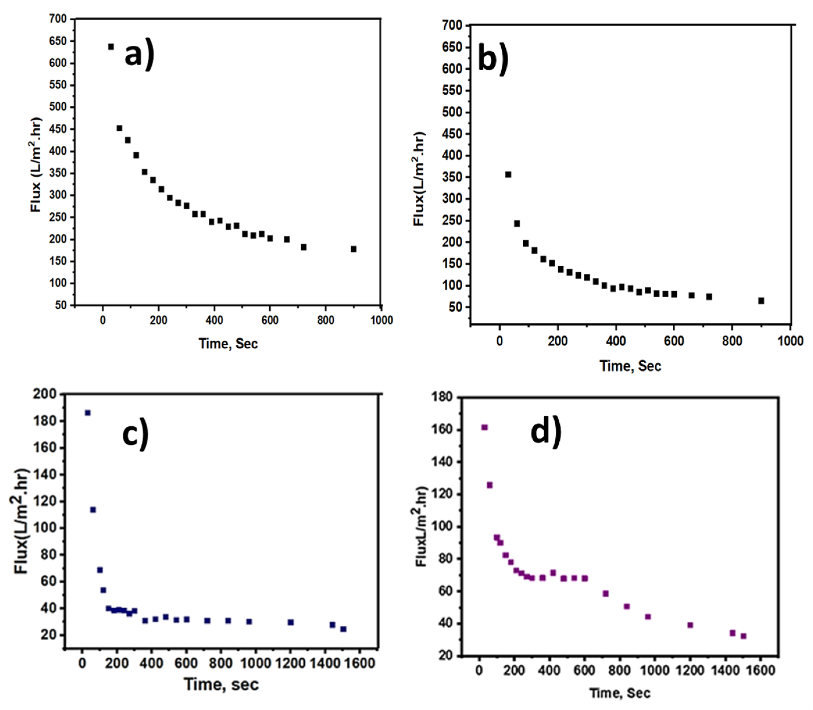
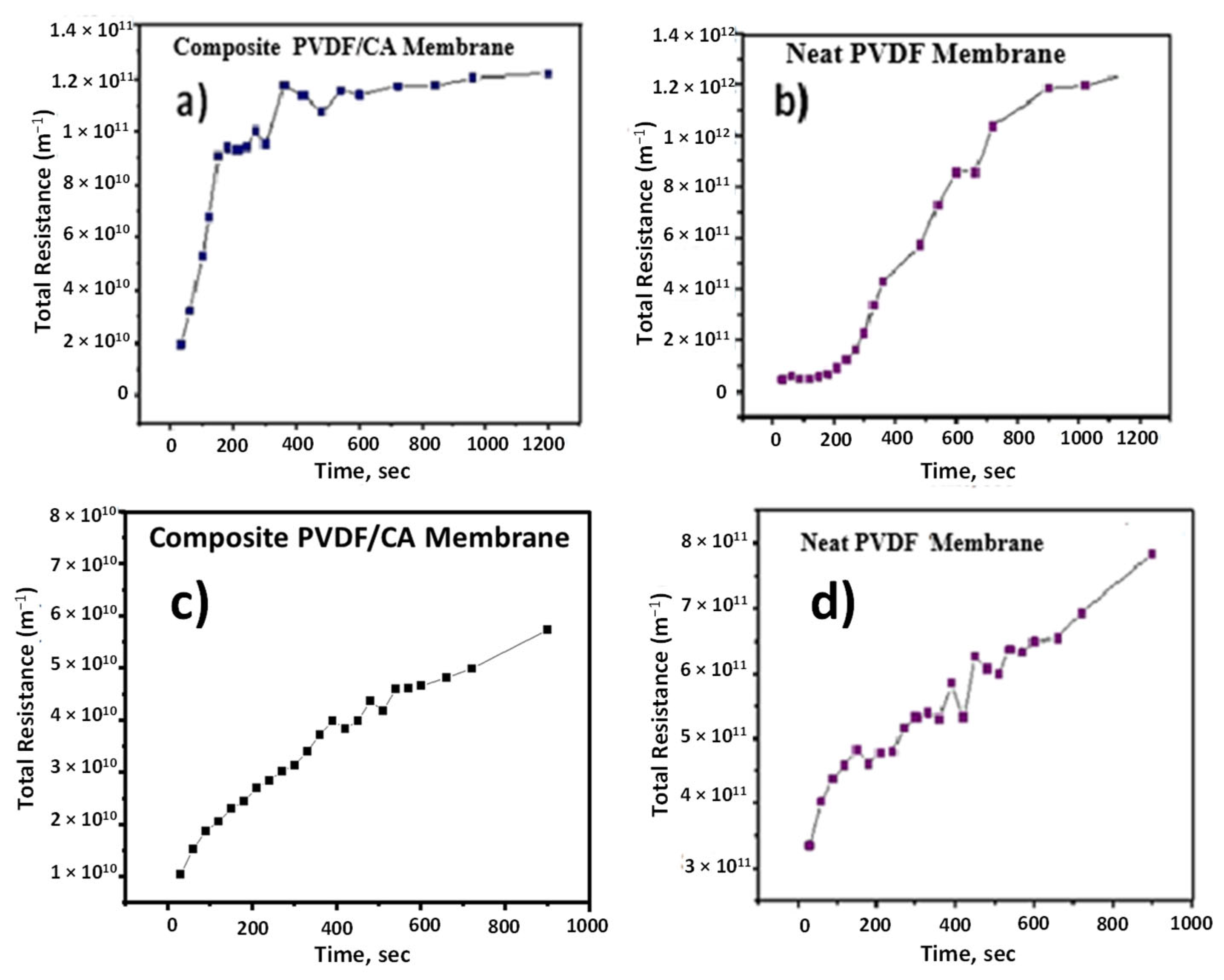
3.6. Water Flux and Filtration Resistance

The clean water flux and wastewater flux were assessed during the dead-end filtration. Initial water flux increased for the composite membrane due to the inherent properties of cellulose acetate. The clean water and wastewater fluxes for the composite membrane were 650 L/m2·h and 190 L/m2·h, respectively, and 350 L/m2·h and 160 L/m2·h, respectively, for the neat PVDF membrane (Figure 8). A higher membrane porosity, as measured, is expected to attract water molecules to the membrane matrix and subsequently make it easier for flow through the membrane (i.e., increasing permeability) [51]. The flux rates all declined as a function of time. Comparing flux rates for the clean water, the ultimate flux rate for the composite PVDF/CA membrane was substantially higher than for the neat PVDF membrane (note the differences in the scale of the Y-axis). While the flux rate of wastewater diminished faster for the composite membrane compared to the neat membrane, the composite material reached an equilibrium state more rapidly that was ultimately greater than that found for the neat material.
Corresponding to the higher flux rates, the PVDF/CA membrane exhibited less resistance compared to the neat PVDF membrane by an order of magnitude for both filtration of clean water and wastewater (Figure 9). A hydration layer is presumably formed on the membrane surface during the filtration process, which mitigates membrane fouling and decreases contaminant adsorption. When pore blocking took place earlier in the filtering process, the fouling resistance (Rt) increased [52,53]. The composite PVDF/CA hydrophilic nanofiber membrane resisted foulants when treated with wastewater. While the wastewater flux results are not definitive, the inherent hydrophilicity of the cellulose acetate when blended with PVDF membrane improved the water flux and membrane antifouling performance.
When considering flux capacity reduction in relation to volume of permeate filtered, the composite PVDF/CA membrane outperformed the neat PVDF membrane (Figure 10). During filtration at a constant pressure of 10 psi, the flux declined for both membranes rapidly at first, but the composite membrane reached an equilibrium while the neat membrane continued to display a diminished flux. The PVDF/CA membrane continued to perform about four times longer than the neat PVDF membrane. This behavior is presumably due to higher hydrophilicity, higher porosity, and larger pore diameter in the PVDF/CA material. As the hydrophobic surface of a membrane increases, organic hydrophobic constituents become more readily attached to the membrane surface due to hydrophobic-hydrophobic interactions [49].
These findings indicate that the hydrophilicity of the composite membrane played a vital role in the filtration of hydrophobic constituents. The strong affinity of water to the CA material likely provides a layer of water molecules on the membrane, which prevents hydrophobic pollutants from attaching to the PVDF/CA material. The presence of hydrophilic atoms (i.e., O and N) in CA increases the wettability of the grafted and cross-linked cellulose acetate membrane, which improves its hydrophilic characteristics through the formation of hydrogen bonds [54]. The hydrophilicity, freedom of electrostatic charges, and motion of hydrated chains all contribute to repulsive interactions with substances such as humic acid [55]. Therefore, the PVDF-CA blend reduced hydrophobic constituent attachment on the membrane surface, which enhanced the antifouling performance of the composite membrane. These findings highlight the potential beneficial use of PVDF/CA composite nanofiber membranes during wastewater treatment.

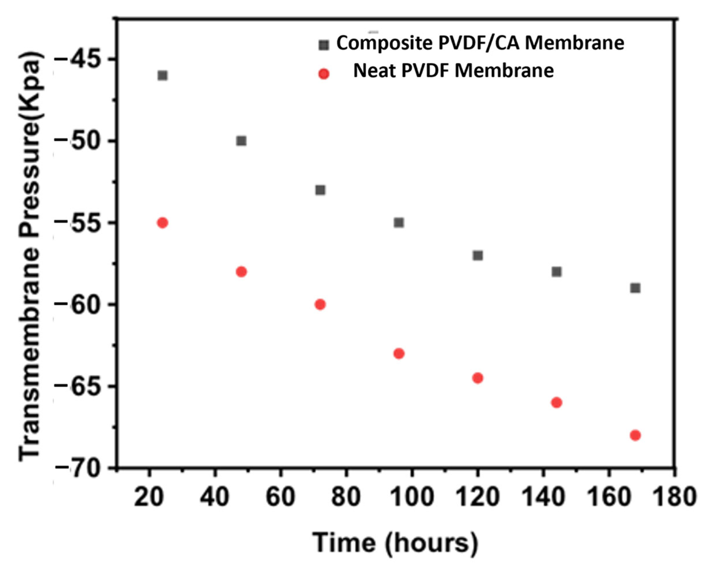
3.7. Submerged Membrane in a Membrane Bioreactor

Evaluation of the two membrane types in a pilot-scale membrane bioreactor was conducted using the configuration shown in Figure 11. Initial tests found that increasing the membrane thickness to 100 mm provided greater durability to pump pressures and allowed for prolonged testing periods. It was necessary to wash the membranes periodically during wastewater treatment because biomass and particle accumulation clogged the membrane surfaces, resulting in reversible fouling that was easily removed [56]. This was achieved using a 0.1 percent hydrochloric acid and 0.5 percent sodium hypochlorite (NAOCL) solution. The initial mixed liquor volatile suspended solids (MLVSS) was 1014 ± 26 mg/L and 1700 ± 49 mg/L during the the reactor operation. Using forced aeration, the dissolved oxygen in the aerobic zone of the reactor was controlled at 2.5 ± 0.2 mg/L, and the temperature of the reactor was maintained at 28 ± 1 °C.
The composite PVDF/CA membrane yielded slightly better wastewater treatment physicochemical parameters than the neat PVDF membrane (Table 7). Notably, chemical oxygen demand (COD) was 92.0 mg/L for the composite membrane (85% reduction), compared to 105.0 mg/L for the neat membrane. Turbidity was reduced by approximately 98% in the bioreactor with the composite membrane, and total suspended solids (TSS) removal approached 100%. The high acidity mixed liquor in the bioreactor resulted in a drop in pH for both nanofiber materials.
A digital transmembrane pressure gauge was installed in the reactor zone to monitor the antifouling performance of the membrane; an increase in transmembrane pressure is a good indicator of increased membrane fouling [57]. Figure 12 demonstrates a substantial difference between the two membrane types, with the composite PVDF/CA membrane exhibiting a lower transmembrane pressure compared to the neat/conventional PVDF membrane. These findings indicate less membrane fouling and better operational efficiency of the composite PVDF/CA membrane.

4. Conclusions

A novel PVDF/CA electrospun nanofiber membrane was successfully created to present a hydrophilic composite membrane that displays enhanced anti-fouling properties. The porosity of the composite PVDF/CA membrane, compared to the neat PVDF membrane, increased from 81% to 91.3%, and wastewater flux increased (160 L/m2·h. vs. 190 L/m2·h). A diminished water contact angle was observed for the composite PVDF/CA membrane from 115° to 101°, indicating enhanced hydrophilicity. The composite membrane exhibited a reduced overall mass transfer resistance and a higher permeability. The transmembrane pressure of the neat PVDF membrane was 68 ± 5 KPa compared to 55 ± 3 KPa for the composite PVDF/CA nanofiber membrane, indicating fouling of the neat PVDF membrane, which limits durability and operational lifespan. This study suggests that the composite PVDF/CA has potential use for municipal and industrial wastewater treatment and the possibility of outperforming non-modified nanofiber membranes.

Author Contributions

Conceptualization, N.B.M. and R.B.M.; methodology, N.B.M.; formal analysis, review, funding acquisition, A.A.S.; investigation, A.M.P. and I.A.; resources, R.B.M.; writing—original draft preparation, N.B.M.; writing—review and editing, J.L.U. and M.I.K.; supervision, R.B.M. All authors have read and agreed to the published version of the manuscript.

Funding

Authors extend their appreciation to the Deanship of Research and Graduate Studies at King Khalid University for funding this work under grant number RGP2/549/46.

Data Availability Statement

The original contributions presented in the study are included in the article. Further inquiries can be directed to the corresponding author.

Acknowledgments

The authors sincerely appreciate the indispensable support provided by Hamdard University, Karachi; Sindh Madressatul Islam University, Karachi; and Dawood University of Engineering and Technology, Karachi, for facilitating a conducive research environment, granting access to essential facilities, and offering other vital resources that significantly contributed to the successful completion of this research.

Conflicts of Interest

The authors declare no conflicts of interest.

References

  1. Khulbe, K.; Feng, C.; Matsuura, T.; Ismail, A. Progresses in membrane and advanced oxidation processes for water treatment. Membr. Water Treat. 2012, 3, 181–200. [Google Scholar] [CrossRef]
  2. Si, J.; Zhao, M.; Marcelle, S.S.A.; Wang, Q.; Cui, Z.; Liu, X. Design and modification of Janus polyvinylidene fluoride/deacetylated cellulose acetate nanofiber membrane and its multifunctionality. Adv. Mater. Interfaces 2023, 10, 2201550. [Google Scholar] [CrossRef]
  3. Kumarage, S.; Munaweera, I.; Kottegoda, N. A comprehensive review on electrospun nanohybrid membranes for wastewater treatment. Beilstein J. Nanotechnol. 2022, 13, 137–159. [Google Scholar] [CrossRef]
  4. Kamalesh, R.; Karishma, S.; Saravanan, A.; Yaashikaa, P. Emerging breakthroughs in membrane filtration techniques and their application in agricultural wastewater treatment: Reusability aspects. Sustain. Chem. Environ. 2024, 8, 100183. [Google Scholar] [CrossRef]
  5. Karki, S.; Hazarika, G.; Yadav, D.; Ingole, P.G. Polymeric membranes for industrial applications: Recent progress, challenges and perspectives. Desalination 2024, 573, 117200. [Google Scholar] [CrossRef]
  6. Wenten, I.; Bazant, M.Z.; Khoiruddin, K. Mitigating electrodialysis membrane fouling in seawater desalination. Sep. Purif. Technol. 2024, 345, 127228. [Google Scholar] [CrossRef]
  7. Du, G.; Tang, K.; Song, C.; Sun, J.; Sun, F.; Chen, C. The operating parameters optimization of LEP-N-MBR system for urban domestic wastewater treatment: Nitrogen and carbon removal, membrane fouling characteristics and microbial community. Sep. Purif. Technol. 2025, 363, 132290. [Google Scholar] [CrossRef]
  8. Ren, L.; Yu, S.; Li, J.; Li, L. Pilot study on the effects of operating parameters on membrane fouling during ultrafiltration of alkali/surfactant/polymer flooding wastewater: Optimization and modeling. RSC Adv. 2019, 9, 11111–11122. [Google Scholar] [CrossRef]
  9. Nguyen, T.; Roddick, F.A.; Fan, L. Biofouling of water treatment membranes: A review of the underlying causes, monitoring techniques and control measures. Membranes 2012, 2, 804–840. [Google Scholar] [CrossRef]
  10. Chen, R.; Nie, Y.; Hu, Y.; Miao, R.; Utashiro, T.; Li, Q.; Xu, M.; Li, Y.-Y. Fouling behaviour of soluble microbial products and extracellular polymeric substances in a submerged anaerobic membrane bioreactor treating low-strength wastewater at room temperature. J. Membr. Sci. 2017, 531, 1–9. [Google Scholar] [CrossRef]
  11. Janga, N.; Ren, X.; Kim, G.; Ahn, C.; Cho, J.; Kim, I.S. Characteristics of soluble microbial products and extracellular polymeric substances in the membrane bioreactor for water reuse. Desalination 2007, 202, 90–98. [Google Scholar] [CrossRef]
  12. Ramesh, A.; Lee, D.-J.; Hong, S. Soluble microbial products (SMP) and soluble extracellular polymeric substances (EPS) from wastewater sludge. Appl. Microbiol. Biotechnol. 2006, 73, 219–225. [Google Scholar] [CrossRef] [PubMed]
  13. Ovez, S.; Turken, T.; Kose-Mutlu, B.; Okatan, S.; Durmaz, G.; Guclu, M.C.; Guclu, S.; Chellam, S.; Koyuncu, I. Manufacturing of antibiofouling polymeric membranes with bismuth-BAL chelate (BisBAL). Desalination Water Treat. 2016, 57, 12941–12955. [Google Scholar] [CrossRef]
  14. Shi, X.; Tal, G.; Hankins, N.P.; Gitis, V. Fouling and cleaning of ultrafiltration membranes: A review. J. Water Process Eng. 2014, 1, 121–138. [Google Scholar] [CrossRef]
  15. Garrett, T.R.; Bhakoo, M.; Zhang, Z. Bacterial adhesion and biofilms on surfaces. Prog. Nat. Sci. 2008, 18, 1049–1056. [Google Scholar] [CrossRef]
  16. Kang, G.-D.; Cao, Y.-M. Application and modification of poly (vinylidene fluoride)(PVDF) membranes—A review. J. Membr. Sci. 2014, 463, 145–165. [Google Scholar] [CrossRef]
  17. Szewczyk, P.K.; Gradys, A.; Kim, S.K.; Persano, L.; Marzec, M.; Kryshtal, A.; Busolo, T.; Toncelli, A.; Pisignano, D.; Bernasik, A. Enhanced piezoelectricity of electrospun polyvinylidene fluoride fibers for energy harvesting. ACS Appl. Mater. Interfaces 2020, 12, 13575–13583. [Google Scholar] [CrossRef]
  18. Cha, B.J.; Yang, J.M. Preparation of poly (vinylidene fluoride) hollow fiber membranes for microfiltration using modified TIPS process. J. Membr. Sci. 2007, 291, 191–198. [Google Scholar] [CrossRef]
  19. Cheng, L.-P. Effect of temperature on the formation of microporous PVDF membranes by precipitation from 1-octanol/DMF/PVDF and water/DMF/PVDF systems. Macromolecules 1999, 32, 6668–6674. [Google Scholar] [CrossRef]
  20. Kong, J.; Li, K. Oil removal from oil-in-water emulsions using PVDF membranes. Sep. Purif. Technol. 1999, 16, 83–93. [Google Scholar] [CrossRef]
  21. Benzinger, W.; Parekh, B.; Eichelberger, J. High temperature ultrafiltration with kynar® poly (vinylidene fluoride) membranes. Sep. Sci. Technol. 1980, 15, 1193–1204. [Google Scholar] [CrossRef]
  22. Chabot, S.; Roy, C.; Chowdhury, G.; Matsuura, T. Development of poly (vinylidene fluoride) hollow-fiber membranes for the treatment of water/organic vapor mixtures. J. Appl. Polym. Sci. 1997, 65, 1263–1270. [Google Scholar] [CrossRef]
  23. Khayet, M.; Khulbe, K.; Matsuura, T. Characterization of membranes for membrane distillation by atomic force microscopy and estimation of their water vapor transfer coefficients in vacuum membrane distillation process. J. Membr. Sci. 2004, 238, 199–211. [Google Scholar] [CrossRef]
  24. Sriyanti, I.; Ramadhani, R.F.; Almafie, M.R.; Ap Idjan, M.K.N.; Syafri, E.; Solihah, I.; Sanjaya, M.R.; Jauhari, J.; Fudholi, A. Physicochemical and mechanical properties of polyvinylidene fluoride nanofiber membranes. Case Study. Chem. Environ. Eng. 2024, 9, 100588. [Google Scholar] [CrossRef]
  25. Pramono, E.; Alfiansyah, R.; Ahdiat, M.; Wahyuningrum, D.; Radiman, C.L. Hydrophilic poly (vinylidene fluoride)/bentonite hybrid membranes for microfiltration of dyes. Mater. Res. Express 2019, 6, 105376. [Google Scholar] [CrossRef]
  26. Wei, D.; Ye, C.; Ahmed, A.; Xu, L. Batch preparation of nanofibers containing nanoparticles by an electrospinning device with multiple air inlets. Beilstein J. Nanotechnol. 2023, 14, 141–150. [Google Scholar] [CrossRef]
  27. Zhao, X.; Zhang, W.; Chen, S.; Zhang, J.; Wang, X. Hydrophilicity and crystallization behavior of PVDF/PMMA/TiO2 (SiO2) composites prepared by in situ polymerization. J. Polym. Res. 2012, 19, 1–9. [Google Scholar] [CrossRef]
  28. Wei, D.W.; Wei, H.; Gauthier, A.C.; Song, J.; Jin, Y.; Xiao, H. Superhydrophobic modification of cellulose and cotton textiles: Methodologies and applications. J. Bioresour. Bioprod. 2020, 5, 1–15. [Google Scholar] [CrossRef]
  29. Liu, C.; Li, X.; Liu, T.; Liu, Z.; Li, N.; Zhang, Y.; Xiao, C.; Feng, X. Microporous CA/PVDF membranes based on electrospun nanofibers with controlled crosslinking induced by solvent vapor. J. Membr. Sci. 2016, 512, 1–12. [Google Scholar] [CrossRef]
  30. Koriem, O.A.; Showman, M.S.; El-Shazly, A.H.; Elkady, M.F. Cellulose acetate/polyvinylidene fluoride based mixed matrix membranes impregnated with UiO-66 nano-MOF for reverse osmosis desalination. Cellulose 2023, 30, 413–426. [Google Scholar] [CrossRef]
  31. Gurave, P.M.; Rastgar, M.; Mizan, M.M.H.; Srivastava, R.K.; Sadrzadeh, M. Superhydrophilic electrospun polyamide-imide membranes for efficient oil/water separation under gravity. ACS Appl. Eng. Mater. 2023, 1, 3134–3146. [Google Scholar] [CrossRef]
  32. Yang, X.; Wang, J.; Guo, H.; Liu, L.; Xu, W.; Duan, G. Structural design toward functional materials by electrospinning: A review. E-Polymers 2020, 20, 682–712. [Google Scholar] [CrossRef]
  33. Esmaeili, A. Wastewater treatment application of nanofibers and their composites. In Polymeric Nanofibers and Their Composites; Elsevier: Amsterdam, The Netherlands, 2025; pp. 227–253. [Google Scholar]
  34. Jiang, S.; Chen, Y.; Duan, G.; Mei, C.; Greiner, A.; Agarwal, S. Electrospun nanofiber reinforced composites: A review. Polym. Chem. 2018, 9, 2685–2720. [Google Scholar] [CrossRef]
  35. Duan, G.; Jin, M.; Wang, F.; Greiner, A.; Agarwal, S.; Jiang, S. Core effect on mechanical properties of one dimensional electrospun core-sheath composite fibers. Compos. Commun. 2021, 25, 100773. [Google Scholar] [CrossRef]
  36. Wang, L.; Dai, S.; Liu, X.; Wang, X.; Lu, H. A ternary system oleophilic–hydrophobic membrane prepared by electrospinning for efficient gravity-driven oil–water separation. SN Appl. Sci. 2019, 1, 797. [Google Scholar] [CrossRef]
  37. Ghanim, M.S.; Soydemir, G.; Yılmaz, F.; Perendeci, N.A.; Karagündüz, A.; Alazaiza, M.Y. Anaerobic Dynamic Membrane Bioreactors (AnDMBRs): Are They an Efficient Way to Treat High-Strength Wastewater? Water 2025, 17, 787. [Google Scholar] [CrossRef]
  38. Ghonimy, M.; Alharbi, A.; Saad, S.A.; Hussein, N.S. Improving Wastewater Quality Using Ultrafiltration Technology for Sustainable Irrigation Reuse. Water 2025, 17, 870. [Google Scholar] [CrossRef]
  39. Shim, J.K.; Na, H.S.; Lee, Y.M.; Huh, H.; Nho, Y.C. Surface modification of polypropylene membranes by γ-ray induced graft copolymerization and their solute permeation characteristics. J. Membr. Sci. 2001, 190, 215–226. [Google Scholar] [CrossRef]
  40. Amy, G. Fundamental understanding of organic matter fouling of membranes. Desalination 2008, 231, 44–51. [Google Scholar] [CrossRef]
  41. Rong, G.; Zhou, D.; Pang, J. Preparation of high-performance antifouling polyphenylsulfone ultrafiltration membrane by the addition of sulfonated polyaniline. J. Polym. Res. 2018, 25, 1–9. [Google Scholar] [CrossRef]
  42. He, W.; Ma, Z.; Yong, T.; Teo, W.E.; Ramakrishna, S. Fabrication of collagen-coated biodegradable polymer nanofiber mesh and its potential for endothelial cells growth. Biomaterials 2005, 26, 7606–7615. [Google Scholar] [CrossRef] [PubMed]
  43. Fong, H.; Chun, I.; Reneker, D.H. Beaded nanofibers formed during electrospinning. Polymer 1999, 40, 4585–4592. [Google Scholar] [CrossRef]
  44. Moradi, G.; Zinadini, S.; Rajabi, L.; Dadari, S. Fabrication of high flux and antifouling mixed matrix fumarate-alumoxane/PAN membranes via electrospinning for application in membrane bioreactors. Appl. Surf. Sci. 2018, 427, 830–842. [Google Scholar] [CrossRef]
  45. Akhondi, E.; Zamani, F.; Law, A.W.; Krantz, W.B.; Fane, A.G.; Chew, J.W. Influence of backwashing on the pore size of hollow fiber ultrafiltration membranes. J. Membr. Sci. 2017, 521, 33–42. [Google Scholar] [CrossRef]
  46. Hou, Y.; Cheng, L.; Zhang, Y.; Yang, Y.; Deng, C.; Yang, Z.; Chen, Q.; Wang, P.; Zheng, L. Electrospinning of Fe/SiC hybrid fibers for highly efficient microwave absorption. ACS Appl. Mater. Interfaces 2017, 9, 7265–7271. [Google Scholar] [CrossRef]
  47. Zheng, W.; Hu, J.; Han, Z.; Wang, Z.; Zheng, Z.; Langer, J.; Economy, J. Synthesis of porous carbon fibers with strong anion exchange functional groups. Chem. Commun. 2015, 51, 9853–9856. [Google Scholar] [CrossRef]
  48. Hu, X.; Chen, Y.; Liang, H.; Xiao, C. Preparation of polyurethane/poly (vinylidene fluoride) blend hollow fibre membrane using melt spinning and stretching. Mater. Sci. Technol. 2011, 27, 661–665. [Google Scholar] [CrossRef]
  49. Xu, Y.; Zou, L.; Lu, H.; Kang, T. Effect of different solvent systems on PHBV/PEO electrospun fibers. RSC Adv. 2017, 7, 4000–4010. [Google Scholar] [CrossRef]
  50. Wang, X.-M.; Waite, T.D. Impact of gel layer formation on colloid retention in membrane filtration processes. J. Membr. Sci. 2008, 325, 486–494. [Google Scholar] [CrossRef]
  51. Hong, J.; He, Y. Effects of nano sized zinc oxide on the performance of PVDF microfiltration membranes. Desalination 2012, 302, 71–79. [Google Scholar] [CrossRef]
  52. Sousa, M.R.S.; Lora-García, J.; López-Pérez, M.-F.; Heran, M. Identification of foulants on polyethersulfone membranes used to remove colloids and dissolved matter from paper mill treated effluent. Water 2020, 12, 365. [Google Scholar] [CrossRef]
  53. Sonune, A.; Ghate, R. Developments in wastewater treatment methods. Desalination 2004, 167, 55–63. [Google Scholar] [CrossRef]
  54. Elkony, Y.; Mansour, E.-S.; Elhusseiny, A.; Hassan, H.; Ebrahim, S. Novel grafted/crosslinked cellulose acetate membrane with N-isopropylacrylamide/N, N-methylenebisacrylamide for water desalination. Sci. Rep. 2020, 10, 9901. [Google Scholar] [CrossRef] [PubMed]
  55. Nakajima, H. Mass Transfer: Advances in Sustainable Energy and Environment Oriented Numerical Modelling; BoD–Books on Demand; InTech: Rijeka, Croatoa, 2013. [Google Scholar]
  56. Aussawasathien, D.; Ketkul, K.; Hrimchum, K.; Threepopnatkul, P. Effects of poly (lactic acid) and polybutylene succinate ratios on properties of composite foams containing activated carbons. In AIP Conference Proceedings; AIP Publishing: Melville, NY, USA, 2019. [Google Scholar]
  57. Gao, S.-S.; Zhang, X.-H.; Geng, M.-Y.; Tian, J.-Y. Effect of membrane material and pore size on membrane fouling during filtration of algae-laden water. Water Sci. Eng. 2025, in press. [Google Scholar] [CrossRef]
Figure 1. The schematic of the dead-end filtration apparatus used to test water flux and membrane fouling.
Water 17 01767 g001
Figure 2. Submerged membrane bioreactor design for simulated wastewater treatment.
Water 17 01767 g002
Figure 3. Scanning electron microscope (SEM) images of (ac) neat PVDF membrane and (df) composite PVDF/CA membrane. (g,h) Histograms of nanofiber diameter for the neat PVDF and composite PVDF/CA membranes, respectively.
Water 17 01767 g003
Figure 4. Energy dispersive spectroscopy (EDS) spectrum for the (a) composite PVDF/CA membrane and (b) neat PVDF membrane.
Water 17 01767 g004
Figure 5. Fourier transform infrared spectrum of the pristine and composite PVDF/CA nanofiber membranes.
Water 17 01767 g005
Figure 6. Tensile strength of neat and composite PVDF/CA nanofiber membranes with varying cellulose acetate concentration: (a) stress-strain performance, (b) stress, (c) strain, and (d) Young’s modulus.
Water 17 01767 g006
Figure 7. Images of water contact angles for the (a) neat PVDF nanofiber membrane, (b) PVDF/CA nanofiber membrane, and (c) error bar graph of water contact angles.
Water 17 01767 g007
Figure 8. (a) Clean water flux across the composite PVDF/CA membrane. (b) Clean water flux across the neat PVDF membrane. (c) Wastewater flux across the composite PVDF/CA membrane. (d) Wastewater flux across the neat PVDF membrane.
Water 17 01767 g008
Figure 9. Resistance during the filtration process: (a) Clean water across the composite PVDF/CA membrane. (b) Clean water flows across the neat PVDF membrane. (c) Wastewater across the composite PVDF/CA membrane. (d) Wastewater flows across the neat PVDF membrane.
Water 17 01767 g009
Figure 10. Flux reduction in (a) the neat PVDF nanofiber membrane and (b) the composite PVDF/CA nanofiber membrane.
Water 17 01767 g010
Figure 11. Photographs of the (a) membrane assembly, (b) bioreactor configuration, and (c) pilot-scale membrane bioreactor installation setup.
Water 17 01767 g011
Figure 12. Transmembrane pressure (TMP) of composite PVDF/CA and neat PVDF membranes.
Water 17 01767 g012
Table 1. Electrospinning parameters for composite PVDF/CA membrane development.
ParametersValue
Distance from the tip of the needle to the collector128–150 mm
Voltage applied22–24 kV
Moisture40–50%
Speed of the metallic collector300 rpm
Speed of the pump filled with polymer solution1.6 mL/min
Needle tip diameter0.006 cm
Membrane drying time18–24 h
Angle of the syringe with the abscissa12 degrees
Table 2. Solution parameters of neat and composite PVDF/CA nanofiber membranes.
SolutionAmbient ConditionsElectrospinning Parameters
Polymer/SolutionCompositionTemperatureHumidityApplied VoltageDistance
PVDF16%80 °C40–45%20 kV10 cm
CA18%25 °C40–45%16 kV11 cm
PVDF/CA80:2025 °C40–45%20 kV11 cm
Table 3. Working parameters of the membrane bioreactor.
ParametersAverage ± Std
Total suspended solids of sludge1700 ± 49 mg/L
Oxygen concentration2.5 ± 0.2 mg/L
Operation time25 days
Temperature28 ± 1 °C
Reactor flowrate14 ± 1 mL/min
Table 4. Properties of wastewater used in the membrane bioreactor.
ParametersAverage ± Std
Total suspended solids78 ± 1.88 mg/L
pH8.3 ± 0.28
Chemical oxygen demand651 ± 22 mg/L
Turbidity37 ± 1.2 NTU
Table 5. Nanofiber physical properties.
Membrane TypeNanofiber Diameter (nm)Pore Size (µm)Porosity (%)
Neat PVDF530 ± 600.51 ± 383 ± 3
Composite PVDF/CA860 ± 830.54 ± 291 ± 2
Table 6. Energy dispersive spectroscopy (EDS) elemental data for the composite PVDF/CA and neat PVDF nanofiber membranes.
Composite PVDF/CANeat PVDF
ElementWeight (%)Atomic (%)Weight (%)Atomic (%)
Carbon21.629.918.025.6
Oxygen10.110.44.04.3
Fluorine68.359.778.070.1
Table 7. Physicochemical parameters following wastewater treatment for the composite PVDF/CA and neat PVDF nanofiber membranes (average values ± standard deviation).
Neat PVDFComposite PVDF/CA
Chemical oxygen demand (mg/L)105.0 ± 892.0 ± 5
Total suspended solids (mg/L)0.000.00
pH7.2 ± 0.16.8 ± 0.3
Turbidity (NTU)1.3 ± 0.6 1.1 ± 0.2
Disclaimer/Publisher’s Note: The statements, opinions and data contained in all publications are solely those of the individual author(s) and contributor(s) and not of MDPI and/or the editor(s). MDPI and/or the editor(s) disclaim responsibility for any injury to people or property resulting from any ideas, methods, instructions or products referred to in the content.

