


Optimized Regulation Scheme of Valves in Self-Pressurized Water Pipeline Network and Water Hammer Protection Research

Abstract
1. Introduction
2. Mathematical Model
2.1. Control Equations
2.2. Characteristic Line Method
2.3. Boundary Conditions
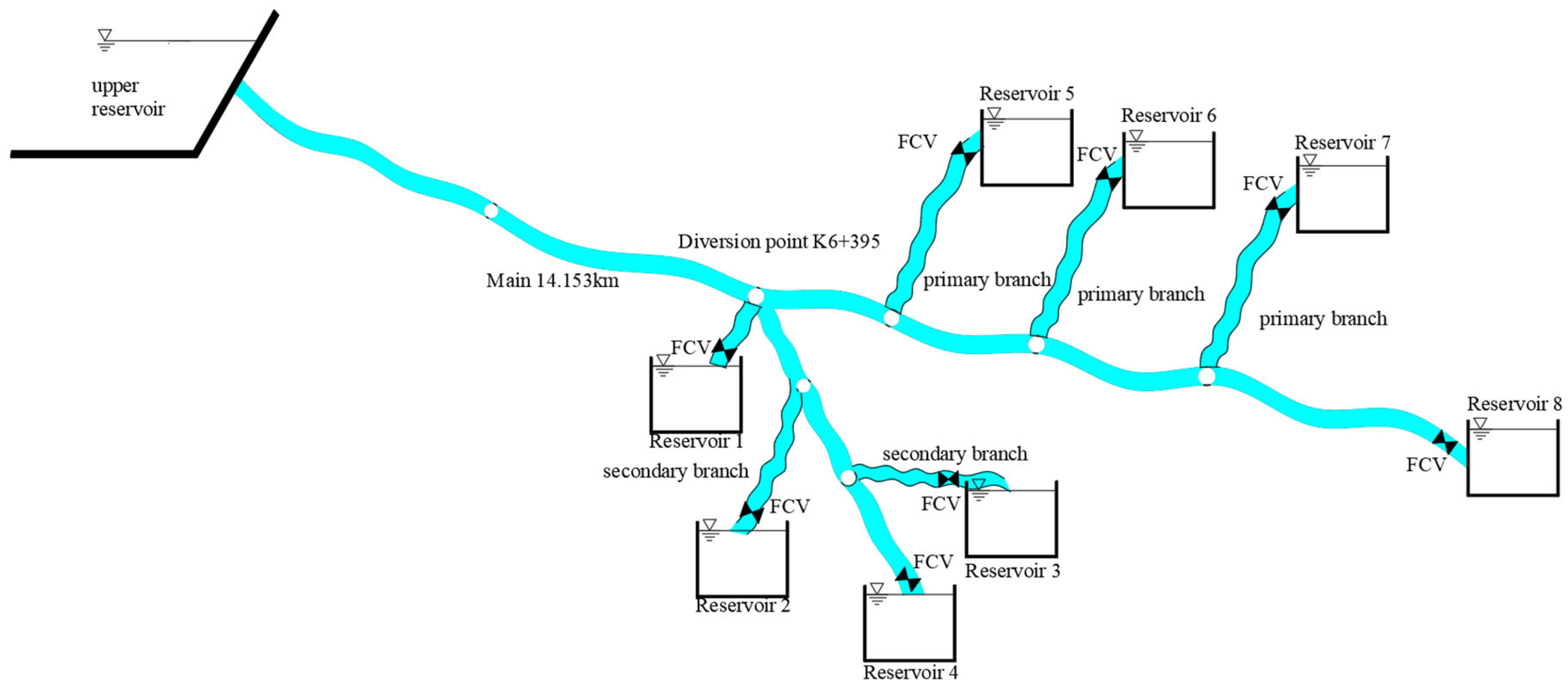
3. Engineering Overview
4. Results and Analysis
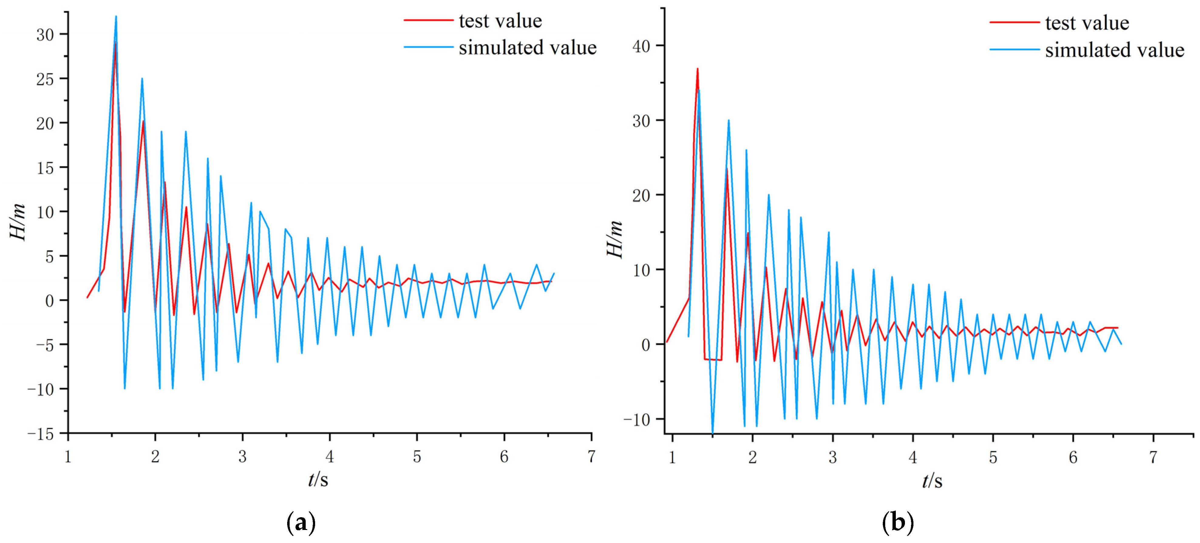
4.1. Model Comparison Validation
4.2. Water Hammer Characterization of Individual Shut-Off Valve Without Protection
4.3. Characterization of Water Hammer Under Unprotected Conditions with Multiple Valves Closed at the Same Time
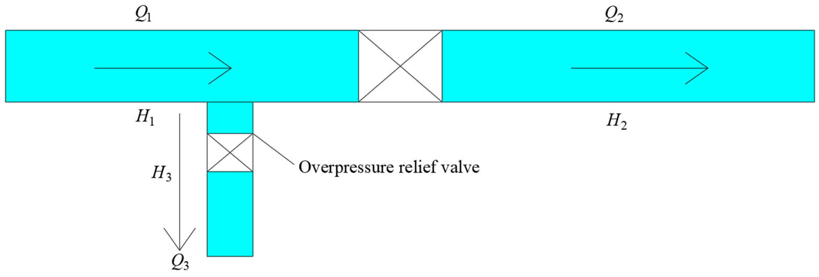
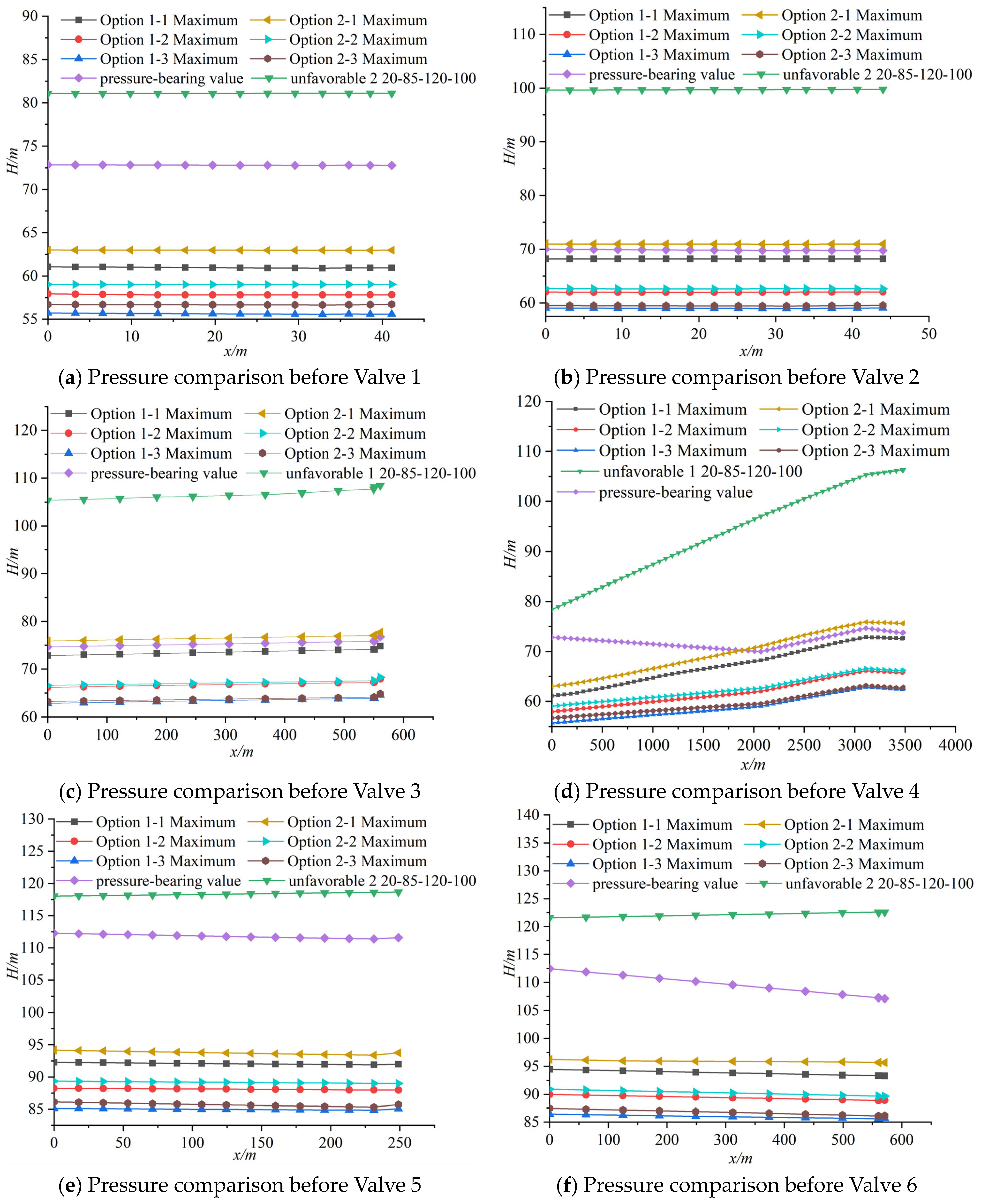
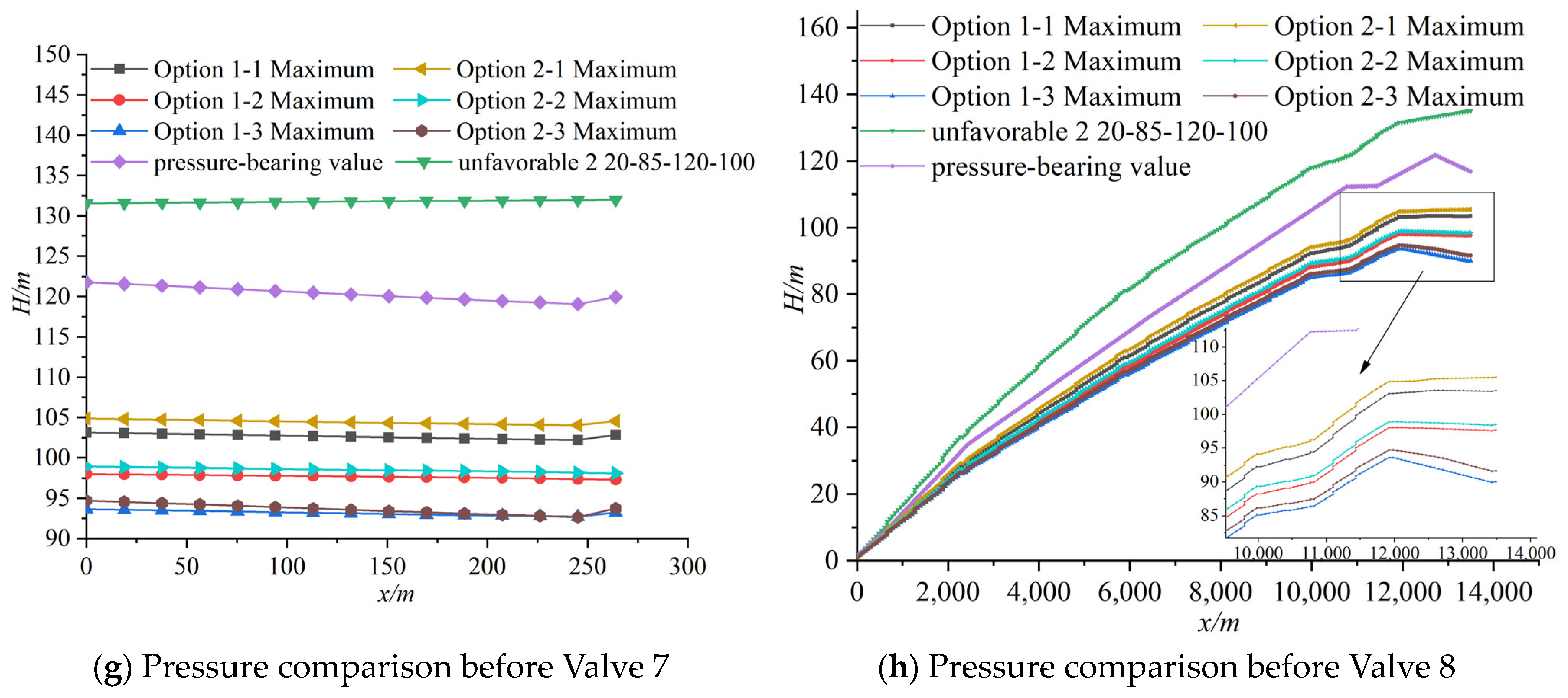
4.4. Analysis of Pipeline Water Hammer When an Overpressure Relief Valve Is Installed in Front of the Valve
- (1)
- The nominal diameter of the pressure relief valve should be between 1/5 and 1/4 of the diameter of the main pipeline. If the pressure inside the pipeline is high and the flow rate is large, the specifications of the pressure relief valve should be recalculated.
- (2)
- The set pressure of the pressure relief valve is typically the relief pressure value of the valve. It is advisable to use 1.2 to 1.3 times the maximum steady-state pressure, and it should not be less than the maximum working pressure plus 0.15 MPa to 0.2 MPa.
- (3)
- As the secondary protection measure for water hammer protection in the water transmission system, the pressure relief valve should respond quickly to high-speed water hammer waves. It should be installed at the node where the water hammer pressure rise is maximum, or the transient pressure or overpressure is the highest, with the installation position as close as possible.
5. Conclusions
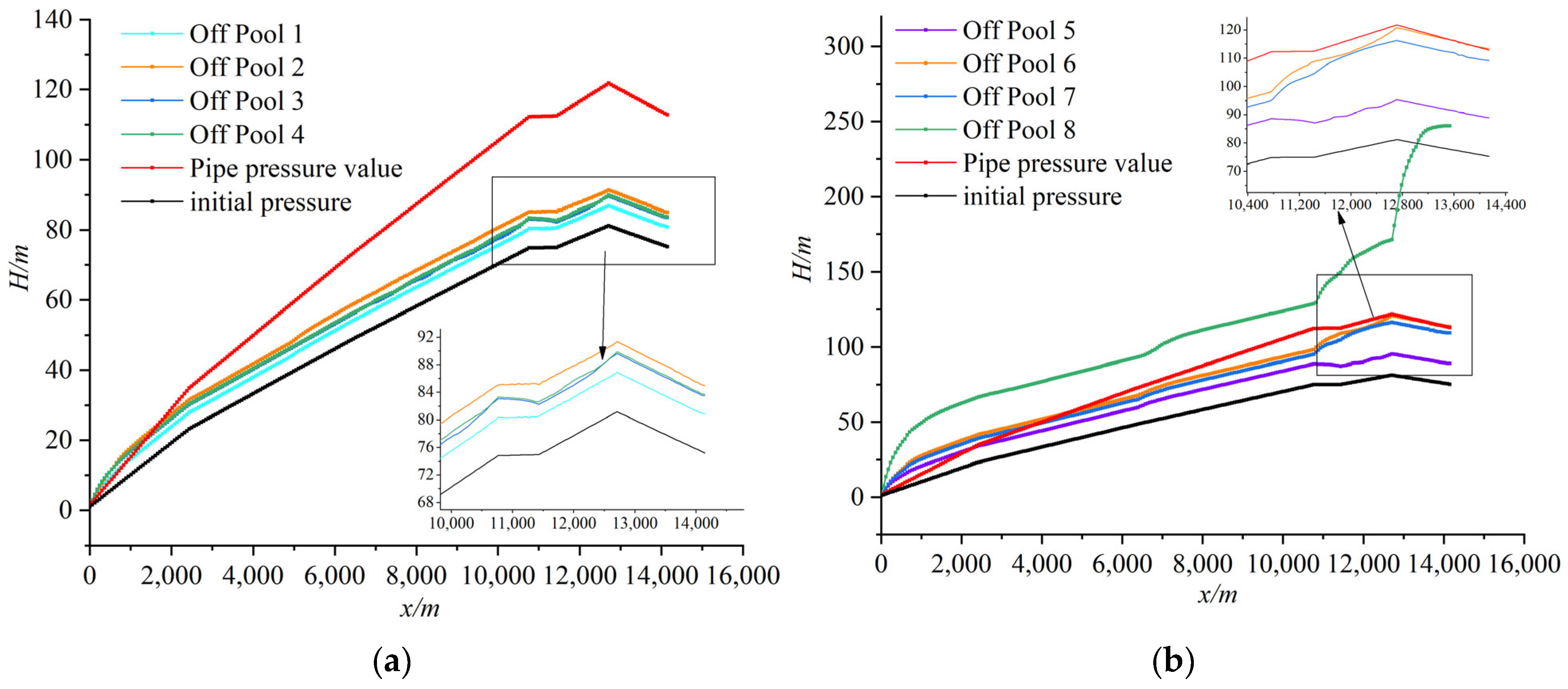
- Under unprotected conditions, when the valves are closed individually for Valves 1–8, the internal pressure reduction is approximately 10.4%, 33.6%, 46.6%, 45.6%, 27.9%, 48.6%, 29.1%, and 56.2%, respectively, to meet the pressure requirements. The two-stage valve closing improves the valve closing efficiency by 33.3%, 66.7%, 73.3%, 75%, 25%, 71.4%, 60%, and 73%, respectively, compared to linear valve closing.
- The simultaneous closure of all valves is not the only most unfavorable operating condition. When multiple valves close simultaneously, the maximum pressures in the Most Unfavorable 1 and Most Unfavorable 2 pipelines are the highest among all operating conditions. The maximum pressures in Branches 1–7 and the main pipeline exceed the pressure rating by 268.6%, 479.3%, 457.3%, 467%, 463.3%, 178%, 220%, 211.3%, and 221.3%, respectively.
- The two-stage valve closing pattern of 20-85-120-100, combined with the overpressure relief valve combination with = 0.25 and = 0.2, forms a joint protection scheme, which reduces the internal pressures in Branches 1–7 by 22%, 14.6%, 15.9%, 15.2%, 23.2%, 19.6%, and 21.9%, respectively, below the pressure rating. It also reduces the maximum pressure in front of the main valve by 21.6%, providing the best protection effect under both individual valve closing and multiple valve simultaneous closing conditions.
Author Contributions
Funding
Data Availability Statement
Conflicts of Interest
References
- Han, Z. Innovation-driven High-quality Development of Water-saving Irrigation to Strengthen the Foundation of Agricultural Power. China Water Resour. 2023, 7, 11–14. [Google Scholar]
- Zhang, M. Research on Valve Closure-Induced Water Hammer and Terminal Reservoir Flow Control in Water Supply Networks; Chang’an University: Xi’an, China, 2021. [Google Scholar]
- Wang, C. Calculation of Pump-stopping Water Hammer in Xinjiang Jundong Wucaiwan Water Supply Project. China Water Supply Drain. 2014, 30, 55–57+61. [Google Scholar]
- Su, D. Hydraulic Fluctuation and Pipeline Vibration Characteristics During Valve Closure in Water Transmission Pipelines; Xi’an University of Technology: Xi’an, China, 2022. [Google Scholar]
- Arefi, M.H.; Ghaeini-Hessaroeyeh, M.; Memarzadeh, R. Numerical modeling of water hammer in long water transmission pipeline. Appl. Water Sci. 2021, 11, 140. [Google Scholar] [CrossRef]
- Zhao, Y. Numerical Study of Transient Flow in Viscoelastic Pipes Based on Energy Analysis; Harbin Institute of Technology: Harbin, China, 2022. [Google Scholar]
- Lohrasbi, A.R.; Attarnejad, R. Water Hammer Analysis by Characteristic Method. Am. J. Eng. Appl. Sci. 2008, 1, 287–289. [Google Scholar] [CrossRef]
- Karadžić, U.; Janković, M.; Strunjaš, F.; Bergant, A. Water Hammer and Column Separation Induced by Simultaneous and Delayed Closure of Two Valves. J. Mech. Eng./Stroj. Vestn. 2018, 64, 525–535. [Google Scholar]
- Wang, Z.; Jia, D.; Ma, C. Optimization study of valve closure scheme for long-distance gravity flow water transfer project. People’s Yellow River 2021, 43, 142–146. [Google Scholar]
- Huang, Y.; Chen, F. Impact of Terminal Valve Closing Mode on Water Hammer Protection in Long Distance Water Transmission Project. People’s Yangtze River 2018, 49, 70–73. [Google Scholar]
- Zhang, D.; Song, X.; Jiang, Y.; Yang, N.; Dong, W. Research on the design of water hammer protection measures for long-distance pressure water transmission projects based on Bentley-Hammer software. Water Supply Drain. 2021, 57, 473–478. [Google Scholar]
- Wang, S.; Guo, X. Water Hammer Protection of Air Tank Based on Bentley Hammer. Vib. Shock. 2022, 41, 177–182+244. [Google Scholar]
- Shi, X.; Lv, D.; Zhu, D. Experimental and numerical simulation of hydraulic transients in branch-type pipe networks. J. Drain. Irrig. Mach. Eng. 2013, 31, 406–412. [Google Scholar]
- Li, N.; Zhang, J.; Shi, L.; Chen, X.; Zhang, X. Joint Water Hammer Protection Characteristics of Air Tanks and Pressure Relief Valves. J. Drain. Irrig. Mach. Eng. 2020, 38, 254–260. [Google Scholar]


| Serial Number | Operating Conditions | Specific Operations |
|---|---|---|
| 1 | Steady-state operation | The mainline inlet is a design flow of 2700 m3/h, and the branch lines are all design flows. |
| 2 | One cistern shut-off valve | There is no protection along the course, the valve in front of the cistern is shut off at 10 s linearly, and the rest of the piping operates normally. |
| Shut-Off Valve Position | Valve Closing Regime | Ratio of Maximum Pressure to Steady State Pressure in the Tube (min. pressure/m) | Valve Closing Regime | Ratio of Maximum Pressure to Steady State Pressure in the Tube (min. pressure/m) | Valve Closing Regime | Ratio of Maximum Pressure to Steady State Pressure in the Tube (min. pressure/m) |
|---|---|---|---|---|---|---|
| 1 | 10 s linear | 1.24 (−0.89) | 30 s linear | 1.13 (−0.23) | 10-85-20-100 | 1.11 (1.48) |
| 2 | 10 s linear | 2.11 (−0.62) | 120 s linear | 1.49 (−0.16) | 10-85-40-100 | 1.40 (1.53) |
| 3 | 10 s linear | 2.68 (0.83) | 150 s linear | 1.49 (1.48) | 10-85-40-100 | 1.43 (1.53) |
| 4 | 10 s linear | 2.65 (−0.71) | 160 s linear | 1.44 (−0.04) | 10-85-40-100 | 1.44 (1.40) |
| 5 | 10 s linear | 1.68 (−1.14) | 40 s linear | 1.25 (−0.27) | 10-85-30-100 | 1.21 (1.43) |
| 6 | 10 s linear | 2.65 (−2.55) | 70 s linear | 1.47 (−0.33) | 10-85-20-100 | 1.36 (1.39) |
| 7 | 10 s linear | 1.89 (−2.16) | 50 s linear | 1.38 (−0.49) | 10-85-20-100 | 1.34 (1.51) |
| 8 | 10 s linear | 3.29 (−9.98) | 260 s linear | 1.49 (1.49) | 20-85-70-100 | 1.44 (1.51) |
| Serial Number | Calculation Condition Name | Concrete Operation |
|---|---|---|
| 1 | Simultaneous valve closure of 2 cisterns | Unprotected along the course, 2 cisterns were selected to shut off the valves at 10 s linearly. Other cisterns are functioning normally. |
| 2 | Simultaneous valve closure of 3 cisterns | Unprotected along the course, 3 cisterns were selected to shut off the valves at 10 s linearly. Other cisterns are functioning normally. |
| 3 | Simultaneous valve closure of 4 cisterns | Unprotected along the course, 4 cisterns were selected to shut off the valves at 10 s linearly. Other cisterns are functioning normally. |
| 4 | Simultaneous closure of 5 cisterns | Unprotected along the course, 5 cisterns were selected to shut off the valves at 10 s linearly. Other cisterns are functioning normally. |
| 5 | Simultaneous closure of 6 cisterns | Unprotected along the course, 6 cisterns were selected to shut off the valves at 10 s linearly. Other cisterns are functioning normally. |
| 6 | Simultaneous closure of 7 cisterns | Unprotected along the course, seven cisterns were selected to shut off the valves at 10 s linearly. Other cisterns are functioning normally. |
| 7 | Simultaneous valve closure of 8 cisterns | Unprotected along the course, the 8 cisterns shut off the valves at the same time in a 10 s linear fashion. |
| Number of Shut-Off Valves | Ratio of Maximum Pressure to Steady State Pressure in the Tube (min. pressure/m) | |||||||
|---|---|---|---|---|---|---|---|---|
| Branch 1 | Branch 2 | Branch 3 | Branch 4 | Branch 5 | Branch 6 | Branch 7 | Supervisor | |
| 2 | 1.78 (44.49) | 1.55 (45.13) | 1.46 (48.38) | 1.76 (44.64) | 1.66 (69.93) | 2.68 (44.98) | 2.13 (60.89) | 2.02 (−1.75) |
| 3 | 2.01 (39.49) | 1.78 (41.97) | 1.66 (45.49) | 1.99 (39.65) | 1.92 (51.89) | 2.71 (53.00) | 2.26 (59.95) | 2.20 (−2.22) |
| 4 | 2.20 (35.03) | 2.42 (42.08) | 2.19 (45.90) | 2.28 (35.35) | 1.95 (56.64) | 2.71 (54.77) | 2.26 (65.99) | 2.20 (−2.63) |
| 5 | 2.44 (27.23) | 3.29 (27.72) | 3.17 (27.23) | 3.46 (26.05) | 2.12 (47.29) | 1.75 (45.38) | 2.42 (56.02) | 2.27 (−2.52) |
| 6 | 2.89 (7.28) | 5.30 (−9.98) | 5.51 (−9.98) | 5.66 (−9.98) | 2.55 (13.39) | 2.93 (2.10) | 2.62 (7.86) | 2.72 (−9.98) |
| 7 | 3.07 (−9.98) | 5.41 (−9.98) | 5.63 (−9.98) | 5.76 (−9.98) | 2.73 (−3.80) | 3.12 (−1.34) | 2.78 (3.31) | 2.89 (−9.98) |
| Number of Shut-Off Valves | Ratio of Maximum Pressure to Steady State Pressure in the Tube (min. pressure/m) | |||||||
|---|---|---|---|---|---|---|---|---|
| Branch 1 | Branch 2 | Branch 3 | Branch 4 | Branch 5 | Branch 6 | Branch 7 | Supervisor | |
| 2 | 2.38 (31.22) | 1.99 (35.90) | 1.87 (39.93) | 2.37 (31.26) | 2.15 (56.96) | 2.74 (19.78) | 2.69 (38.78) | 3.30 (−8.02) |
| 3 | 3.08 (−9.98) | 2.49 (10.02) | 2.33 (14.90) | 3.06 (3.91) | 2.66 (3.22) | 3.46 (−9.98) | 3.49 (−9.98) | 3.99 (−9.98) |
| 4 | 3.42 (−9.98) | 2.81 (3.31) | 2.58 (5.86) | 3.39 (−2.77) | 3.01 (−9.98) | 3.75 (−9.98) | 3.59 (−9.98) | 4.00 (−9.98) |
| 5 | 3.61 (−9.98) | 3.87 (−9.98) | 3.56 (5.40) | 3.68 (−9.98) | 3.04 (−9.98) | 3.75 (−9.98) | 3.59 (−9.98) | 4.00 (−9.98) |
| 6 | 3.79 (−9.98) | 4.87 (−9.98) | 4.71 (−6.23) | 4.68 (−9.98) | 3.05 (−9.98) | 3.75 (−9.98) | 3.48 (−9.98) | 4.00 (−9.98) |
| 7 | 4.19 (−9.98) | 7.05 (−9.98) | 8.36 (−9.98) | 8.51 (−9.98) | 3.64 (−9.98) | 4.00 (−9.98) | 3.84 (−9.98) | 4.27 (−9.98) |
| shut out | 5.53 (−9.98) | 8.69 (−9.98) | 8.00 (−9.98) | 8.45 (−9.98) | 4.17 (−9.98) | 4.80 (−9.98) | 4.67 (−9.98) | 4.82 (−9.98) |
| Closing Rule | Ratio of Maximum Pressure to Steady State Pressure in the Tube (min. pressure/m) | |||||||
|---|---|---|---|---|---|---|---|---|
| Branch 1 | Branch 2 | Branch 3 | Branch 4 | Branch 5 | Branch 6 | Branch 7 | Supervisor | |
| 10-85-100-100 | 1.72 (37.73) | 2.25 (42.63) | 2.27 (46.48) | 2.31 (37.73) | 1.66 (59.56) | 1.92 (58.86) | 1.72 (65.60) | 1.87 (1.00) |
| 20-85-120-100 | 1.68 (44.51) | 2.22 (46.56) | 2.24 (49.83) | 2.28 (44.53) | 1.62 (68.42) | 1.67 (68.12) | 1.67 (75.15) | 1.82 (1.00) |
| 20-85-80-100 | 1.77 (35.31) | 2.32 (39.23) | 2.34 (43.11) | 2.38 (35.34) | 1.71 (55.77) | 1.98 (55.07) | 1.77 (62.01) | 1.92 (1.00) |
| 20-85-100-100 | 1.80 (33.44) | 2.38 (37.98) | 2.40 (41.64) | 2.44 (33.48) | 1.73 (54.65) | 2.01 (53.36) | 1.79 (59.77) | 1.96 (1.00) |
| 30-85-80-100 | 2.17 (17.72) | 2.83 (22.56) | 2.83 (24.22) | 2.87 (17.79) | 2.02 (34.95) | 2.32 (33.90) | 2.07 (38.59) | 2.26 (1.00) |
| 30-85-120-100 | 1.72 (41.92) | 2.25 (46.56) | 2.27 (49.83) | 2.31 (41.94) | 1.66 (64.85) | 1.71 (64.19) | 1.72 (71.03) | 1.87 (1.00) |
| Closing Rule | Ratio of Maximum Pressure to Steady State Pressure in the Tube (min. pressure/m) | |||||||
|---|---|---|---|---|---|---|---|---|
| Branch 1 | Branch 2 | Branch 3 | Branch 4 | Branch 5 | Branch 6 | Branch 7 | Supervisor | |
| 10-85-100-100 | 1.66 (41.93) | 2.19 (46.56) | 2.21 (49.83) | 2.25 (41.95) | 1.61 (64.83) | 1.88 (65.20) | 1.67 (71.03) | 1.83 (1.00) |
| 20-85-120-100 | 1.60 (44.51) | 2.11 (46.56) | 2.13 (49.83) | 2.16 (44.53) | 1.56 (68.40) | 1.68 (68.12) | 1.62 (75.15) | 1.76 (1.00) |
| 20-85-80-100 | 1.58 (39.95) | 1.94 (46.31) | 1.96 (49.83) | 1.98 (39.98) | 1.46 (61.78) | 1.57 (61.16) | 1.51 (68.17) | 1.64 (1.00) |
| 20-85-100-100 | 1.74 (38.50) | 2.30 (45.55) | 2.33 (49.80) | 2.37 (38.52) | 1.68 (60.72) | 1.95 (59.56) | 1.74 (66.12) | 1.90 (1.00) |
| 30-85-80-100 | 1.70 (25.65) | 2.25 (29.56) | 2.28 (30.99) | 2.31 (25.64) | 1.66 (42.51) | 1.92 (42.63) | 1.72 (47.46) | 1.87 (1.00) |
| 30-85-120-100 | 2.06 (41.92) | 2.70 (46.56) | 2.73 (49.83) | 2.77 (41.94) | 1.94 (64.82) | 2.24 (64.19) | 2.00 (71.03) | 2.20 (1.00) |
| Programmatic | Worst Case Scenario | (MPa) | Programmatic | Worst Case Scenario | (MPa) | ||
|---|---|---|---|---|---|---|---|
| 1-1 | 1 | 0.20 | 0.2 | 2-1 | 2 | 0.20 | 0.2 |
| 1-2 | 1 | 0.225 | 0.2 | 2-2 | 2 | 0.225 | 0.2 |
| 1-3 | 1 | 0.25 | 0.2 | 2-3 | 2 | 0.25 | 0.2 |
Disclaimer/Publisher’s Note: The statements, opinions and data contained in all publications are solely those of the individual author(s) and contributor(s) and not of MDPI and/or the editor(s). MDPI and/or the editor(s) disclaim responsibility for any injury to people or property resulting from any ideas, methods, instructions or products referred to in the content. |
© 2025 by the authors. Licensee MDPI, Basel, Switzerland. This article is an open access article distributed under the terms and conditions of the Creative Commons Attribution (CC BY) license (https://creativecommons.org/licenses/by/4.0/).
Share and Cite
Zheng, Y.; Tan, Y.; Li, L.; Zhang, Q. Optimized Regulation Scheme of Valves in Self-Pressurized Water Pipeline Network and Water Hammer Protection Research. Water 2025, 17, 1534. https://doi.org/10.3390/w17101534
Zheng Y, Tan Y, Li L, Zhang Q. Optimized Regulation Scheme of Valves in Self-Pressurized Water Pipeline Network and Water Hammer Protection Research. Water. 2025; 17(10):1534. https://doi.org/10.3390/w17101534
Chicago/Turabian StyleZheng, Yunpeng, Yihai Tan, Lin Li, and Qixuan Zhang. 2025. "Optimized Regulation Scheme of Valves in Self-Pressurized Water Pipeline Network and Water Hammer Protection Research" Water 17, no. 10: 1534. https://doi.org/10.3390/w17101534
APA StyleZheng, Y., Tan, Y., Li, L., & Zhang, Q. (2025). Optimized Regulation Scheme of Valves in Self-Pressurized Water Pipeline Network and Water Hammer Protection Research. Water, 17(10), 1534. https://doi.org/10.3390/w17101534