Article

Mechanical Response Study of a Cross-Fault Water Conveyance Tunnel under the Combined Action of Faulting Dislocation and Seismic Loading

by
Maochu Zhang
1,2,3,*,
Tianyou Yan
1,2,3,
Zhen Cui
3,4,*,
Jianhe Li
1,2,3 and
Ran Xu
1,2,3
1
Changjiang Design Group Co., Ltd., Wuhan 430010, China
2
Changjiang Survey, Planning, Design and Research Co., Ltd., Wuhan 430010, China
3
State Key Laboratory of Water Resources Engineering and Management, Wuhan 430072, China
4
State Key Laboratory of Geomechanics and Geotechnical Engineering, Institute of Rock and Soil Mechanics, Chinese Academy of Sciences, Wuhan 430071, China
*
Authors to whom correspondence should be addressed.
Water 2024, 16(20), 2876; https://doi.org/10.3390/w16202876
Submission received: 12 August 2024 / Revised: 13 September 2024 / Accepted: 13 September 2024 / Published: 10 October 2024

Abstract

:
This paper investigated the response of a cross-fault water conveyance tunnel under the combined action of faulting dislocation and seismic loading. The current work studied the mechanical properties of the wall rock–lining contact surface. Finite difference method (FDM) code was used for the numerical simulation test to reproduce the shear test and calibrate the parameters. In the analysis of the combined faulting dislocation and strong earthquake impact on the cross-fault tunnel, the FDM was used with special consideration of the wall rock–lining interaction. The result showed that the Coulomb contact model in the FDM code could satisfactorily simulate the shear behavior of wall rock–lining contact surface. In the mechanical response calculation of the cross-fault tunnel under the faulting dislocation–seismic loading action, the magnitude of the initial faulting distance had a significant effect on the seismic relative deformation of the tunnel. The permanent deformation caused by the seismic loading increased with the initial faulting dislocation. The position of the maximum shear stress on the contact interface was related to the faulting dislocation mode, and it was distributed on the side of the tunnel squeezed by the active plate. In the high seismic risk regions with extensive development of active faults, it was necessary to consider the initial crack caused by the faulting dislocation in the stability evaluation of the cross-fault tunnel. Then, the seismic resistance study of the tunnel was followed.

1. Introduction

China is carrying out the construction of its national water network, and a large number of major water diversion projects have been implemented one after another. The long tunnel is an important infrastructure for building the national water network and is widely used in water diversion projects, including in the western region of China. The western region of China is located in the compression zone between the Indian plate and the Eurasian plate, where faults are distributed and earthquakes occur frequently [1,2]. To accommodate the needs of national transportation and resource allocation, many transportation and water conservancy infrastructures have been constructed in this western region [3,4,5,6]. Due to the constraints of various factors, the long tunnel project in western China will inevitably cross the active fault zone during construction. In past seismic studies, underground structures were shown to be more earthquake-resistant than above-ground structures [7,8]. The safety and stability of tunnels have therefore become key issues that urgently need to be solved in engineering design.
In recent years, the investigations after earthquakes found that the damage to the tunnel by the earthquake indicated a strong correlation to the location of the fault [9,10,11]. The statistical results after the Chichi earthquake in Taiwan showed that tunnels in the fault zone were almost unavoidably damaged during the earthquake [12]. Specifically, one tunnel in the fault dislocation region and three tunnels in the fault footwall zone were severely damaged in the earthquake. During the Wenchuan earthquake, landslides, cracks and concrete lining movement occurred in the section of the Longxi tunnel spanning the fault [13,14]. The effect of the active fault zone on tunnel safety is shown in two aspects, one is the dislocation damage cause by creeping fault, while the other is the seismic hazard caused by the near-fault earthquake. When the tunnel crosses an active fault zone, it encounters fault creep dislocation, and the stability of the tunnel is reduced dramatically [15,16,17,18,19,20]. If an earthquake subsequently occurs, it causes a greater threat to the safety of the tunnel. Anastasopoulos et al. [18] investigated the behavior of a deep immersed tunnel in Greece under the combined effect, using a simplified 3D massive flexural beam model. Mahsa et al. [19] analyzed the mechanical response of a cylindrical tunnel under the combined influence of the main near-fault seismic excitation and the subsequent reverse fault rupture. Yang et al. [20] studied the motivation response of the tunnel–fault system by using a 3D discrete element model combined with the physical ground motion records of the Wenchuan earthquake. Caulfield et al. [5] studied the influence of the faulting and strong earthquake vibration on the Claremont Tunnel crossing the Hayward strike–slip active fault, and they designed a systematic anti-seismic and anti-fault measures to ensure the normal operation during the project. The study of the stability of tunnels across faults has thus become an important scientific problem in engineering design. In addition, when a tunnel is built into the wall rock, a contact surface is formed between the wall rock and the tunnel lining. If a fault creep dislocates or an earthquake occurs, the rock transmits tangential and normal loads onto the surface of the engineered lining. Thus, shear and compression stress states would occur on this contact interface. In turn, the wall rock–lining interaction would affect the deformation mechanism and stability of the tunnel lining [21,22,23].
In this work, the parameters of the wall rock–lining contact surface were investigated by shear testing of the wall rock–lining contact samples. Based on the laboratory results, numerical simulations of the wall rock–lining contact surface were carried out. The parameters in the numerical simulation were determined by comparison with the results of the laboratory shear testing. The 3D model of the cross-fault tunnel was built in FDM software (Flac3d 7.0). Thereafter, two main influencing factors, the fault mode and initial faulting dislocation distance, were considered. The response and failure features of the tunnel under the fault action–strong earthquake were studied. To better understand the dynamic response of cross-fault tunnels, many key characteristics, including the stress distribution, deformation, and plastic zone, were investigated.

2. Shear Tests of Wall Rock–Lining Contact Surfaces

2.1. Test Procedure

The creep slip of active faults and near-fault earthquakes causes deformation and destruction of the wall rock mass and tunnel lining. The extrusion and shear of the interface between the wall rock and the lining can lead to the closure and sliding of the wall rock and the lining system, which represents the main component of the wall rock and the lining interaction. The stability and deformation analyses of rock engineering such as tunnels (caves) require reliable data on the behavior of the contact surface. Experimental study is the most direct and important method to obtain mechanical parameters. Here, the Brazil splitting test of square rock samples was adopted to make the model of the wall rock–lining contact surface (Figure 1a) [24]. With 3D scanning and 3D printing technology, a solid model of the contact surface was produced (Figure 1b,c). The solid model has the same shape and roughness as the split rock surface; therefore, it was used for the restoration of the rock splitting surface. The contact surface model was inlaid in the middle of the casting mold (Figure 1d). The mold was poured into the simulated material of the wall rock and the structure (Figure 1e) [25]. The simulated materials of the wall rock and lining were made of quartz sand, cement and water according to the strength requirements in the specifications [26,27]. Finally, the wall rock–lining contact samples were combined (Figure 1f). Two kinds of contact samples of the rock splitting surface were produced in this work, denoted J1 and J2, respectively.
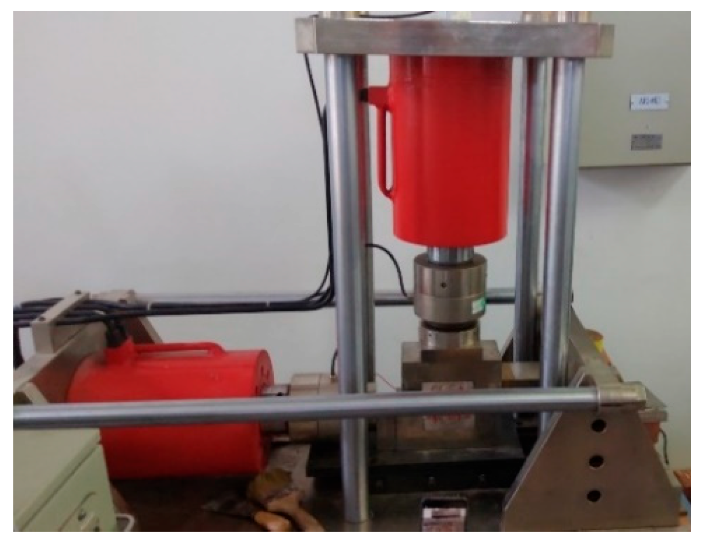
Then, shear tests of the wall rock–lining composite specimens were carried out on a CNL+CNS rock structural plane shear tester (RJST-616) (Figure 2) [28]. In this test, five normal stress levels were set for the contact surface samples (J1 and J2): 0.5 MPa, 1.0 MPa, 1.5 MPa, 3.0 MPa and 5.0 MPa, and the loading rate was 0.005 mm/s. The parameters of the interface were determined by the shear testing results.

2.2. Test Results

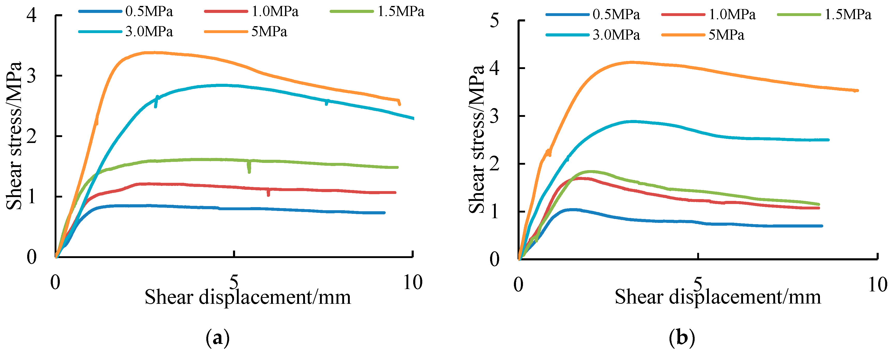
The shear test curves of the wall rock–lining contact surface are shown in Figure 3. According to the experimental results, the shearing strength of the specimens is obtained. Then, the peak shear stiffness of the contact surface can be obtained from the peak shear strength and shear displacement up (peak value). This embodies a very important parameter in the numerical calculation when considering the interaction of the wall rock and lining. According to the shear stress and shear displacement curve of the contact surface sample, the peak shearing stiffness is obtained by Equation (1).
k s = τ u p
where k s is the peak shearing stiffness, τ is the shearing strength, and u p is the shearing displacement.
Figure 4 shows the relationship between the peak shearing stiffness of the wall rock–lining contact sample and its normal stress. It can be seen that the peak shearing stiffness of the contact surface increases with the increase in normal stress. A linear relationship between the peak shearing stiffness and normal stress is fitted out.

3. Numerical Simulation Test of the Wall Rock–Lining Interface

3.1. Numerical Simulation Model

At present, the interaction between the wall rock and lining remains incompletely considered in the research as it pertains to the seismic response analysis of cross-fault tunnels. Based on the laboratory shear test results of the wall rock–lining contact specimens, numerical simulation of the contact surfaces are carried out in this work. The parameters of the interface in the FDM soft are determined by comparison with the laboratory shear data. A bridge is therefore built to relate the experimental research to the numerical simulations.
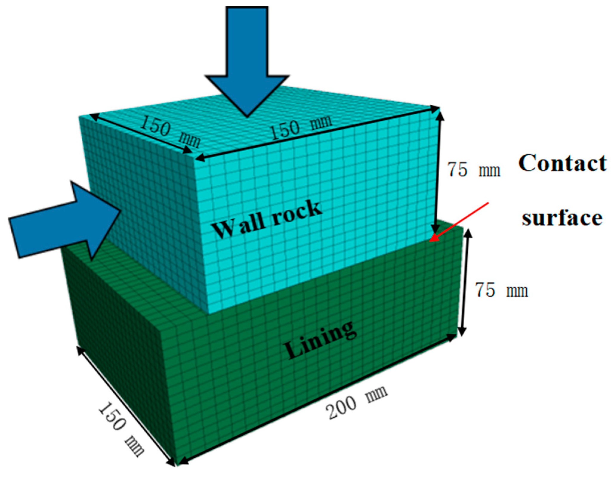
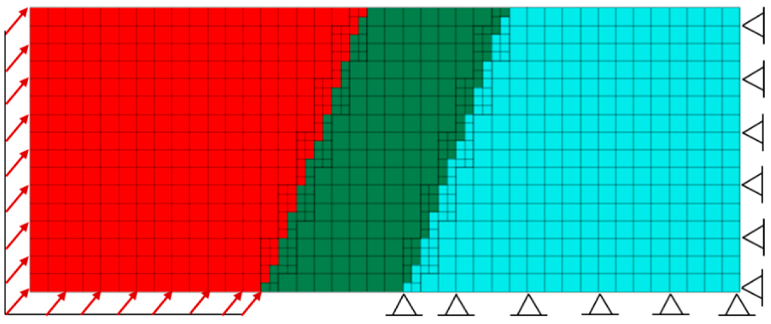
An FDM model for the shear simulation test of the wall rock–lining contact sample is shown in Figure 5. The size of the upper block is 150 mm × 150 mm × 75 mm. The size of the lower block is 200 mm × 150 mm × 75 mm. Hexahedral elements are used to divide the mesh in the FDM model. The contact surface element is assigned the non-thick contact surface element in the FDM model. The contact element establishes the connection between the contact surface node and the solid element surface. According to the different contact states and the corresponding constraints, the contact stress–displacement relationship is deduced to form the constitutive relationship of the contact elements. The Coulomb contact model is taken as the constitutive model for the interface. To ensure a fair comparison of the simulation with the laboratory shear test, the numerical analysis proceeds in the same way as the laboratory testing. In the numerical experiment, we set the same normal stress as in the indoor experiment. Five tests at different normal stress levels of 0.5 MPa~5.0 MPa are performed for each combination. The shear displacements and shear stresses on the contact surfaces are recorded during the numerical tests. The material mechanical parameters of the blocks are listed in Table 1.

3.2. Numerical Simulation Test Results

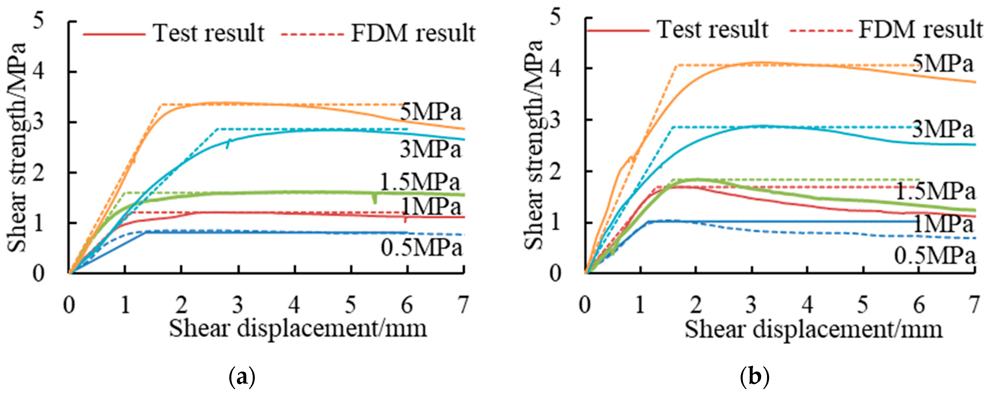
Figure 6 shows the comparison between the numerical simulation test and the laboratory shear test of the wall rock–lining contact surface. The numerical simulation of the contact surface test curve and the laboratory shear curve fit well in the rising section before the peak value. The peak shear strength measured by the two methods is close to the same degree. The results show that the linear Coulomb model could satisfactorily simulate the shearing behavior of wall rock–lining interface. The mechanical parameters of the contact surface used in the numerical test are listed in Table 2.
These parameters are also directly used in the parameter setting of the wall rock–lining contact surface in the subsequent cross-fault tunnel model. It provides a foundation for the study of the response of the cross-fault tunnel, considering the interaction between the wall rock and lining.

4. Mechanical Response of a Cross-Fault Tunnel in Consideration of the Wall Rock–Lining Interaction

4.1. Establishment of the Numerical Model of the Cross-Fault Tunnel

A single active fault mainly includes the hanging wall, footwall and fracture zone. Under creep slip dislocation, the fault hanging wall and footwall force the rock mass to constantly rub together, forming a 100 m or even kilometer-scale fracture zone. The fault disk that bears the displacement and deformation of the main body when there is an active fault dislocation is set as the active plate. To study the failure law of a cross-fault tunnel under the combined action of faulting dislocation and seismic loading, a 3D model of the tunnel cross-fault model is built. The model comprises wall rock and a circular tunnel passing through it. The wall rock includes a fault hanging wall, footwall and fault fracture. Assuming that the wall rock and fault fracture are homogeneous, considering the wall rock–lining interaction, an interface is set between the wall rock and the lining. The settings and values of the contact surface elements are the same as described in Section 3. First, no contact surface is set in the calculation model, the wall rock or the lining share nodes. After the fault slips for a certain distance, the normal stress at the junction of the wall rock and concrete lining is extracted, and the mechanical parameters of the shear test of the contact surface under this stress are selected as the setting parameters of the wall rock–lining interface. This contact surface allows relative sliding, separation and compression between the wall rock and concrete lining.
Figure 7 shows a 3D model of a tunnel-crossing fault. The boundary size of the model is 20 m × 50 m × 20 m. The inner diameter of the tunnel is 2.65 m. The thickness of tunnel lining is 0.75 m. The fault fracture width is 10 m. The dip of the active fault is 70°. Hexahedral elements are used to divide the model mesh, and the maximum grid size is 1.25 m [29,30]. Optimizing the tradeoff between the calculation accuracy, the model of the fracture zone is divided into finer grids. According to the rock mass classification system of China [26], the rock mass is classified into grades I~V. The rock mass quality gradually deteriorates from grade I to grade V. In this study, the hanging wall of the fault is set as grade III rock mass. The footwall of the fault is set as grade IV rock mass. The fault fracture zone is grade V rock mass. The wall rock and lining adopted the M-C constitutive model. The material parameters of the active fault and tunnel lining are listed in Table 3.

4.2. Numerical Analysis Procedure of the Cross-Fault Tunnel under the Combined Action of Faulting and Seismic Loading

To establish a numerical analysis procedure for the cross-fault tunnels under the action of faulting dislocation and seismic loading, two important simulation steps need to be carried out. The first step is the simulation analysis of the faulting dislocation. The second step is the application of seismic loading after the faulting dislocation. The parameters of the contact surface are obtained from the laboratory and numerical simulation tests of the contact specimens. Considering the interaction of the wall rock and the concrete lining, the analysis mode of the cross-fault tunnel under the combined action of faulting and a strong earthquake is simulated.
Step 1: Initial faulting dislocation simulation. Consider the simulation of thrust, where fault dislocation is taken as an example. The bottom and right edge of the fault footwall are fastened. At the bottom and left boundary of the hanging wall, a uniform speed is applied at the nodes on the outer surface of the activity wall. The velocity direction is upward along the fault dip. The middle fault fracture zone does not have any constraints. To avoid the dynamic influence of fault movement on the lining, the initial faulting dislocation is only applied at a low rate of 0.01 mm/time-step in the numerical simulation. The initial faulting dislocation simulation is shown in Figure 8.
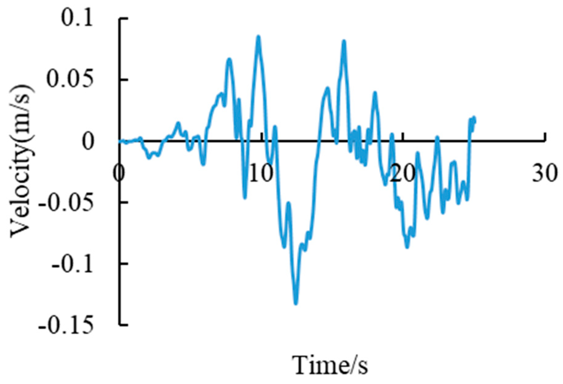
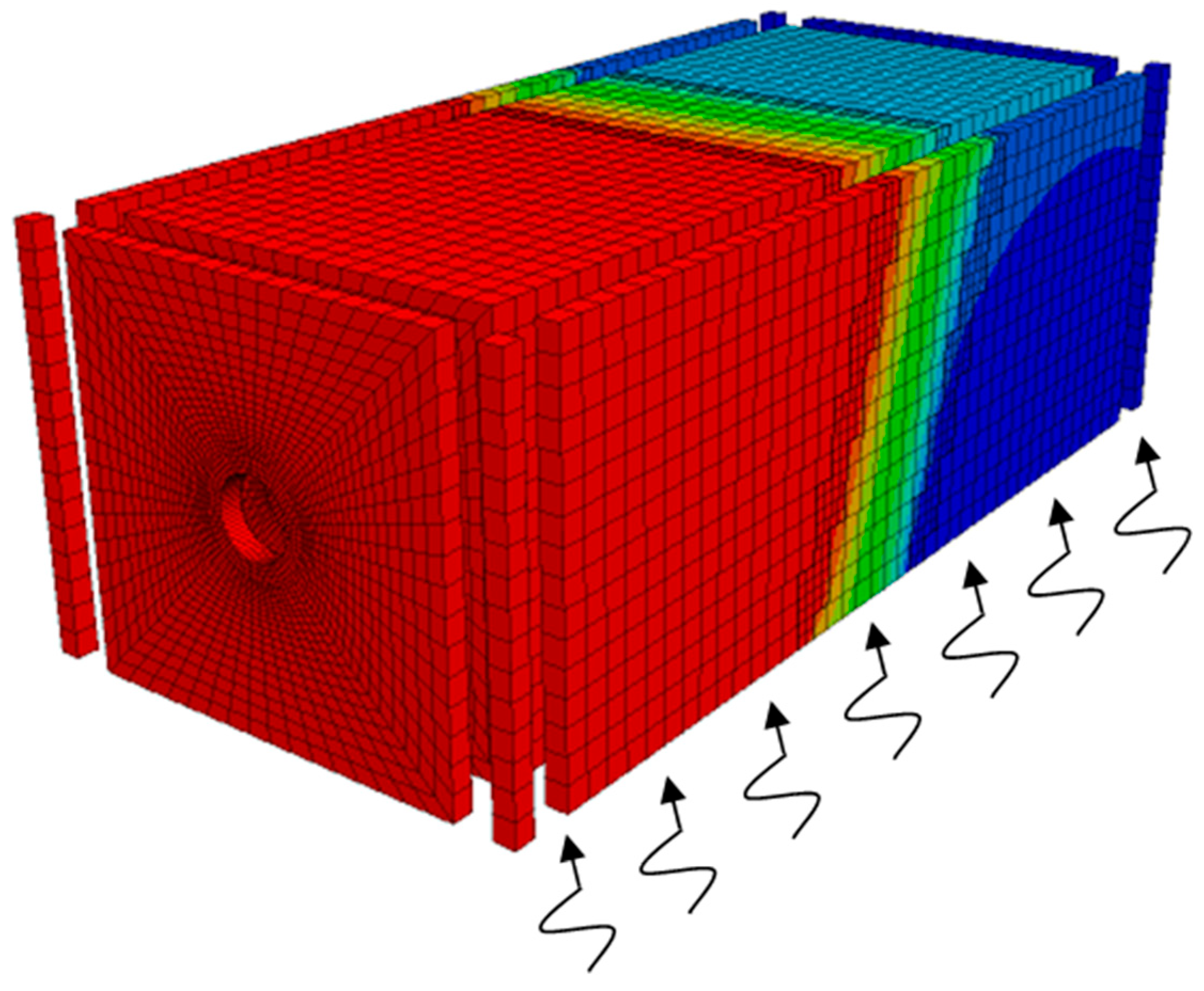
Step 2: The initial displacement and damage caused by the faulting dislocation in the first step are retained. Then, the fixed boundary and dislocation velocity established in Step 1 are removed. The free field boundaries are applied around the model and the viscous boundaries are applied at the top and bottom of the model. Finally, the 25 s Wenchuan (platform record of the 2008 Wenchuan earthquake) wave is input from the model bottom to simulate the earthquake action (Figure 9). The simulation of the cross-fault tunnel under the action of faulting dislocation and seismic loading is shown in Figure 10.

4.3. Mechanical Response Monitoring Scheme of the Cross-Fault Tunnel

According to the study by Oh and Moon [31], the deformation of underground structures subjected to seismic loading conditions includes transverse and longitudinal deformations. To analyze the combined response of the tunnel under the fault dislocation–seismic loading, the monitoring scheme is formulated as follows. The monitoring layout diagram of the cross-fault tunnel mechanical response monitoring is shown in Figure 11.
Along the axis direction of the tunnel, three transversal sections are selected in the middle of the fault walls and fault fracture of the cross-fault tunnel model. The stress and deformation are recorded at the top, bottom, left and right sides of the lining. The dynamic response of the lining during seismic loading is recorded.

4.4. Mechanical Response of a Cross-Fault Tunnel under the Combined Action of Faulting Dislocation and Seismic Loading

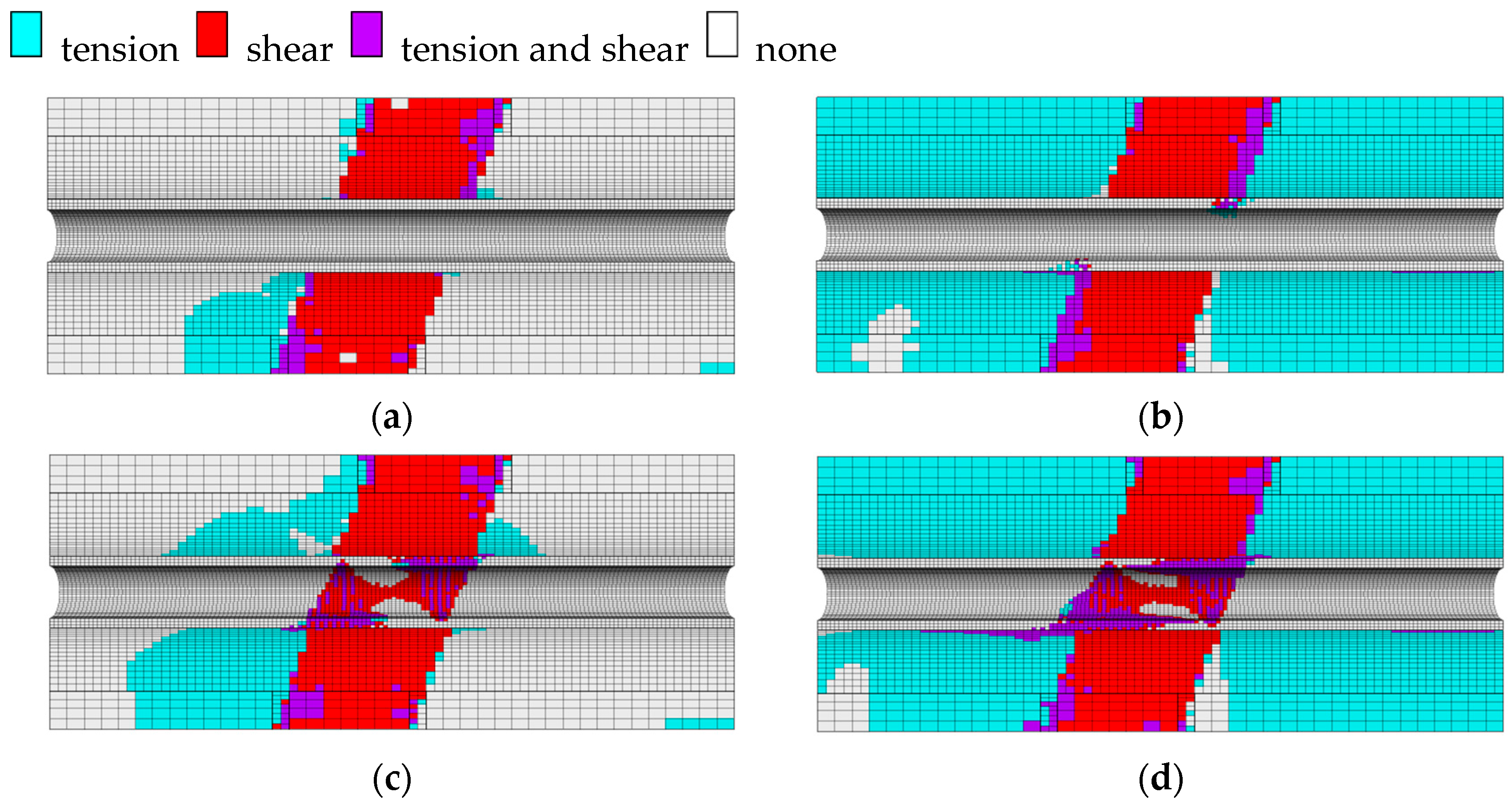
Figure 12 shows the plastic zone of the cross-fault tunnel model under the combined action of faulting dislocation–seismic loading. It can be seen from the distribution of the plastic zone that, as the initial dislocation displacement of the fault increases, the area of the plastic failure of the tunnel increases after seismic loading. After the fault hanging wall elevates 30 cm along the fault dip angle, the shear failure mainly occurs in the fault fracture zone (Figure 12c). At the bottom of the passive fault plate, strain failure occurs. The boundary between the fault fracture zone and the hanging and foot walls is subjected to tension–shear failure. After the action of faulting and seismic loading, the wall rock exhibits a wide range of tensile failure, and the fault fracture zone remains shear failure. At the boundary between the fault fracture zone and the hanging and foot walls, the tension–shear failure is aggravated.
Figure 13 shows the characteristics of the plastic zone in the concrete lining. The plastic zone of the tunnel increases when the dislocation distance of the fault is large. The failure of the lining mainly occurs at the fault fracture zone, and the main failure mode of the lining is shear failure. At the boundary between the fault fracture zone and the hanging and foot walls, the failure modes of the lining are tensile failure and shear failure.
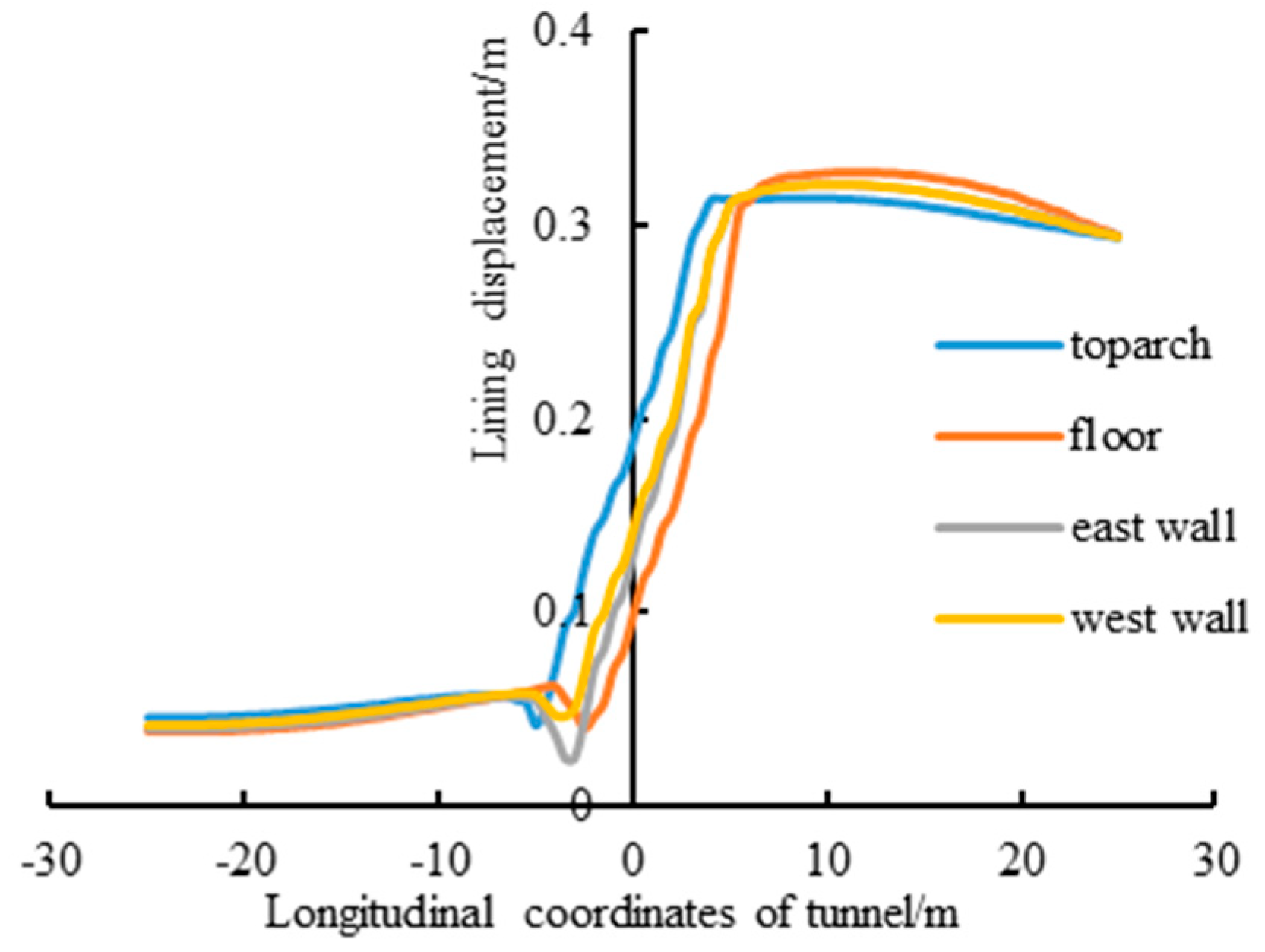
Figure 14 shows the longitudinal deformation of the tunnel after 30 cm of faulting dislocation–seismic loading; Figure 15 shows the longitudinal seismic deformation of the tunnel excluding the initial dislocation distance. The fault mode is reverse fault. As seen from the results, the inflection point of the deformation occurs at the boundary between the fault fracture zone and the hanging and foot walls. The deformation on the east and west sides of the tunnel is more serious than that on the top and bottom. The longitudinal seismic deformation of the tunnel floor is 6 cm higher than that of the faulting stage. Seismic and faulting dislocation resistance measures should be taken in response.
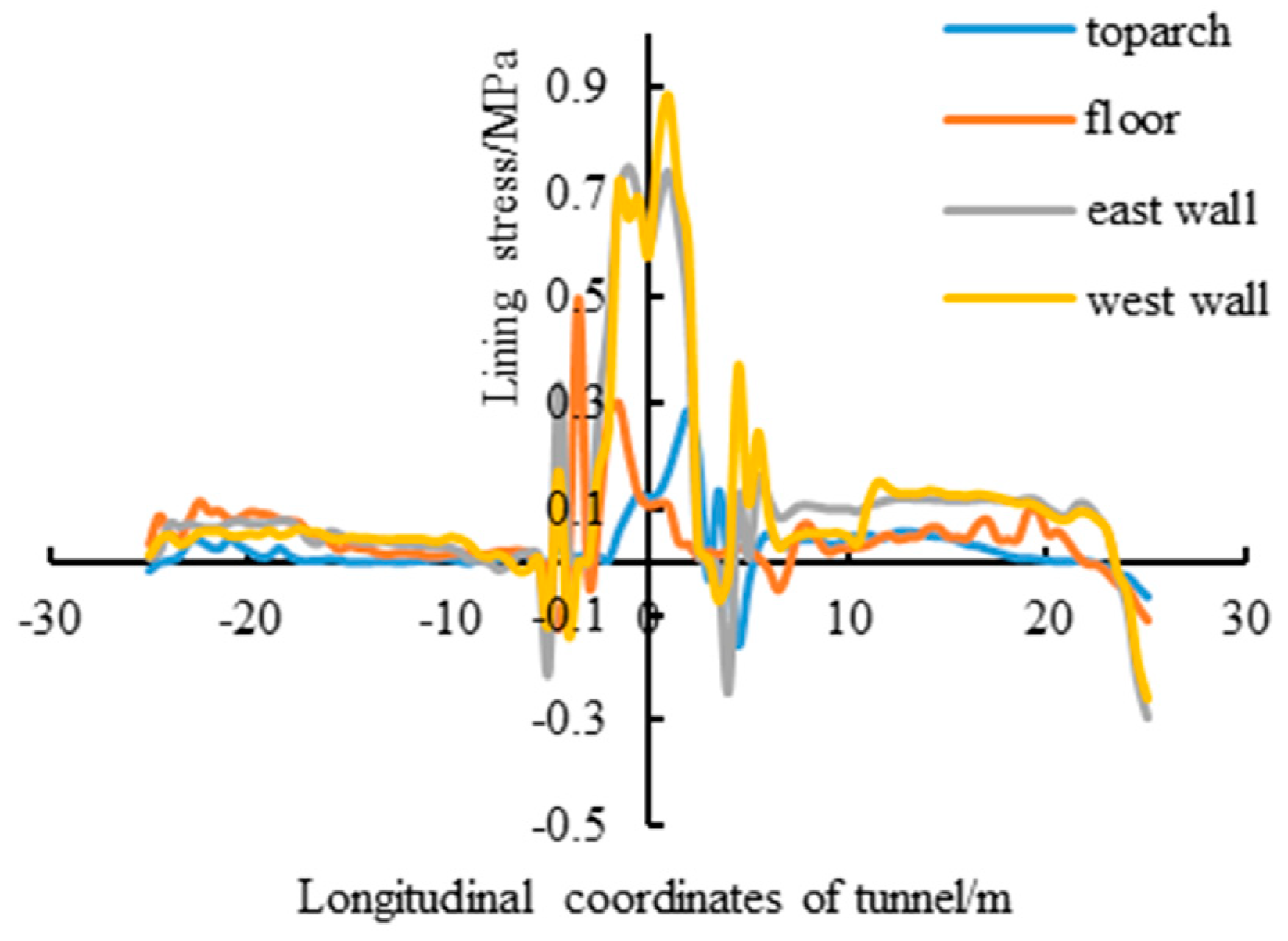
Figure 16 shows the stress of the concrete lining after a 30 cm faulting dislocation–seismic loading. Figure 17 shows the seismic stress of the concrete lining excluding the initial dislocation stress. As can be seen from the results, there exists a large earthquake-based tensile stress on the tunnel in the fracture zone. After the action of faulting dislocation–seismic loading, the cross-fault tunnel experiences greater tensile stress compared with the tensile stress during the initial faulting dislocation. Stress monitoring is carried out around the tunnel. By comparison, the stresses on both sides of the tunnel are higher than the stresses at the top and bottom. The tensile stress at the fault fracture zone increases by 0.9 MPa. Therefore, the seismic resistance of the tunnel in the fault fracture zone should be paid more attention. Corresponding anti-seismic measures should be adopted when implementing projects in the field.

4.5. Dynamic Response Analysis of the Wall Rock–Lining Contact Surface

4.5.1. Effect of Different Fault Modes on the Dynamic Response of the Cross-Fault Tunnel

Figure 18 shows the shear stress of the interface under the action of seismic loading after the initial 30 cm faulting dislocation. There are clear differences in the dynamic response of the cross-fault tunnel under the different fault modes. By comparing the shear stress on the interface of the wall rock and concrete lining, it is found that the position of the maximum shear stress on the contact surface is related to the fault dislocation mode. The maximum shear stress is concentrated at the tunnel located on the active side. The shear stress of the interface is the smallest in the normal fault mode, and the shear stress in the reverse fault and strike–slip fault modes is greater. Therefore, it is necessary to determine the proper anti-seismic measures in engineering design according to the physical fault mode.

4.5.2. Effect of Different Initial Faulting Distances on the Seismic Response of the Cross-Fault Tunnel

The comparison of the shear stress at the interface with different initial dislocation distances is presented in Figure 19. The shear stress on the interface of the wall rock and concrete lining increases with an increasing dislocation distance. The maximum value of the shear stress is concentrated near the fault plane and at the boundary between the fault fracture zone and the hanging and foot walls.
The initial displacement of the faulting dislocation exhibits an important influence on the seismic response of the contact surface of the cross-fault tunnel under the action of faulting dislocation and seismic loading. The large faulting displacement causes large deformation on the contact surface at the boundary between the fault fracture zone and the hanging and foot walls, and then it causes damage to the tunnel section there. After the action of faulting dislocation and seismic loading, a large deformation occurred in the fault fracture zone and wall rock, and the tunnel damage was aggravated.

4.6. Seismic Response of the Cross-Fault Tunnel after Initial Faulting Deformation

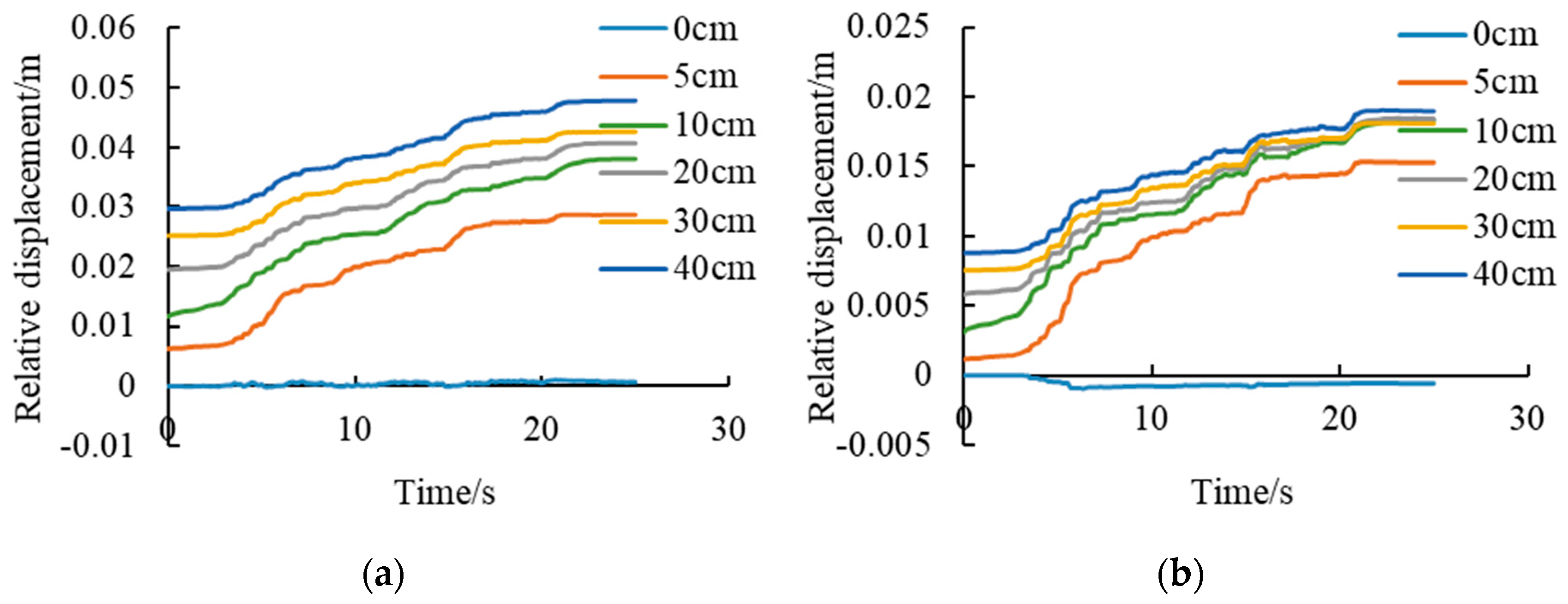
The seismic dynamic response of the concrete lining in the middle of the fault fracture zone is also monitored. Figure 20 shows the time history curve of the relative deformation of the tunnel in the fault fracture zone. As can be seen from the figure, when there is no initial faulting dislocation, the relative deformation of the top and bottom of the tunnel in the fault fracture zone is small under only the seismic load. Considering the initial faulting dislocation, the deformation of the tunnel located in the fault fracture zone increases with the increase of the earthquake time. The higher the initial displacement of the fault, the greater the relative deformation of the tunnel after the earthquake. Considering the initial faulting damage, the relative deformation of the tunnel’s two sidewalls in the fault fracture zone increases with an increasing earthquake time. However, the relative deformation of both sidewalls of the tunnel is less than that of the roof and bottom. When the initial faulting distance increased to 20 cm, the deformation of the left and right sidewalls increased from 0.5 cm to more than 1.5 cm, and the deformation of the roof and floor increased from 2 cm to 4 cm after the earthquake.

5. Conclusions

In this study, a cross-fault water conveyance tunnel under the action of faulting dislocation–seismic loading is investigated. A 3D numerical model for crossing an active fault tunnel is built. The mechanical parameters of the contact surface are determined by laboratory shear testing and numerical simulations of the wall rock–lining contact samples. Considering the interaction between the wall rock and concrete lining, the dynamic response of the water conveyance tunnel under the actions of faulting dislocation and seismic loading is studied. The fault mode and dislocation displacement are determined to be the two key factors affecting the mechanical properties of the cross-fault tunnel. The following discussion summarizes the results obtained here.
(1)
Numerical simulations with FDM software can reproduce the shear test of the wall rock–lining interface. The Coulomb model can better simulate the shear mechanical behavior of the wall rock–lining interface. Linear fitting of the pre-peak curve and simulation of the peak intensity are achieved.
(2)
In the seismic response of a cross-fault tunnel under the action of faulting dislocation and seismic loading, the magnitude of the initial faulting dislocation exhibits a significant effect on the relative deformation of the tunnel. The larger the initial faulting distance, the larger the permanent relative deformation and the more serious the tunnel damage. In addition, the responses of different parts of the tunnel are different. The failure of the concrete lining is mainly concentrated in the range of the fault fracture zone, and the main failure mode of the lining is shear failure. At the boundary between the fault fracture zone and the hanging and foot walls, the failure modes of the concrete lining are tensile and shear failure.
(3)
The position of the maximum shear stress on the interface of the wall rock and tunnel lining is related to the fault mode. The maximum value of the shear stress is concentrated on the tunnel near the active fault side. The shear stress of the interface is smallest in the normal fault mode, and the shear stress in the reverse fault and strike–slip fault modes is larger. Considering the initial faulting damage, the relative deformation of the deformation of the tunnel located in the fault fracture zone increases with an increasing earthquake time.
(4)
The initial faulting dislocation of an active fault demonstrates an impact on the seismic performance of the lining structures. Therefore, in the region of the active fault distribution and areas with frequent earthquakes, it is necessary to consider the initial damage caused by the active fault and then carry out relevant seismic resistance studies.

Author Contributions

Writing—original draft preparation, methodology, software, data curation, M.Z.; Conceptualization, Writing—review and editing, software, supervision, Z.C. Conceptualization, software, supervision, T.Y. Writing—review and editing, validation, supervision, J.L. Writing—review and editing, R.X. All authors have read and agreed to the published version of the manuscript.

Funding

This research was funded by a fellowship from the China National Postdoctoral Program for Innovative Talents (no. BX20230303), a fellowship from the China Postdoctoral Science Foundation (no. 2024M752747), the Major Science and Technology Project of the Ministry of Water Resources (no. SKS-2022103), and the post-doctoral innovation practice positions in Hubei province (no. 2023CXGW03).

Data Availability Statement

Data are contained within the article.

Conflicts of Interest

Authors Maochu Zhang, Tianyou Yan, Jianhe Li and Ran Xu were employed by the Changjiang Design Group Co., Ltd. and Changjiang Survey, Planning, Design and Research Co., Ltd. The remaining authors declare that the research was conducted in the absence of any commercial or financial relationships that could be construed as a potential conflict of interest.

References

  1. Cui, Z.; Sheng, Q.; Leng, X.L. Control effect of a large geological discontinuity on the seismic response and stability of underground rock caverns: A case study of the Baihetan #1 surge chamber. Rock Mech. Rock Eng. 2016, 49, 2099–2114. [Google Scholar]
  2. Zhang, X.H.; Fu, P.; Yin, J.M.; Liu, K.Y. In-situ stress characteristics and active tectonic response of Xianglushan tunnel of Middle Yunnan Water Diversion Project. Chin. J. Geotech. Eng. 2021, 43, 130–139. [Google Scholar]
  3. Si, J.Z.; Zeng, Y.C.; Liu, J.B. Challenges and some thoughts on open-TBM construction in a railway tunnel with complex geologies. Tunn. Constr. 2021, 41, 433–440. [Google Scholar]
  4. Wang, R.B.; Wang, X.Y.; Zhang, W.Q.; Xu, W.Y.; Lu, J.B.; Xiang, T.B. Physical model experiment of external water pressure in lining surrounding rock of a deep tunnel with cross fault. J. Tsinghua Univ. (Sci. Technol.) 2024, 64, 1179–1192. [Google Scholar]
  5. Wang, W.D.; Li, J.Y.; Han, Z. Comprehensive assessment of geological hazard safety along railway engineering using a novel method: A case study of the Sichuan-Tibet railway, China. Geomat. Nat. Hazards Risk 2020, 11, 1–21. [Google Scholar] [CrossRef]
  6. Zhu, Y.T.; Niu, X.Q.; Tian, J.Z. A machine vision-based intelligent segmentation method for dam underwater cracks using swarm optimization algorithm and deep learning. Comput.-Aided Civ. Infrastruct. Eng. 2024, 1–13. [Google Scholar] [CrossRef]
  7. Shi, W.; Wang, R.; Wang, Q.Y. Research review of the response displacement method for aseismic design of underground structures. Sci. Technol. Eng. 2024, 24, 61–71. [Google Scholar]
  8. Zhuang, H.Y.; Wang, R.; Shi, P.X.; Chen, G.X. Seismic response and damage analysis of underground structures considering the effect of concrete diaphragm wall. Soil Dyn. Earthq. Eng. 2019, 116, 278–288. [Google Scholar] [CrossRef]
  9. Aygar, E.B.; Gokceoglu, C. Problems encountered during a railway tunnel excavation in squeezing and swelling materials and possible engineering measures: A case study from Turkey. Sustainability 2020, 12, 1166. [Google Scholar] [CrossRef]
  10. Hashimoto, S.; Fujino, Y.; Abe, M. Damage analysis of hanshin expressway viaducts during 1995 kobe earthquake. II: Damage mode of single reinforced concrete piers. J. Bridge Eng. 2005, 10, 54–60. [Google Scholar] [CrossRef]
  11. Wang, Z.Z.; Gao, B.; Jiang, Y.J.; Yuan, S. Investigation and assessment on mountain tunnels and geotechnical damage after the Wenchuan earthquake. Sci. China Ser. E Technol. Sci. 2009, 52, 546–558. [Google Scholar] [CrossRef]
  12. Roy, N.; Sarkar, R. A review of seismic damage of mountain tunnels and probable failure mechanisms. Geotech. Geol. Eng. 2017, 35, 1–28. [Google Scholar] [CrossRef]
  13. Chen, Z.Y.; Shi, C.; Li, T.B.; Yuan, Y. Damage characteristics and influence factors of mountain tunnels under strong earthquakes. Nat. Hazards 2012, 61, 387–401. [Google Scholar] [CrossRef]
  14. Tao, S.J.; Gao, B.; Wen, Y.M.; Zhou, X. Investigation and analysis on the seismic damage of mountain tunnels subjected to Wenchuan earthquake. Appl. Mech. Mater. 2011, 99–100, 273–281. [Google Scholar] [CrossRef]
  15. Xiong, W.; Fan, W.; Peng, J.B.; Deng, L.S.; Yan, F.Y. Numerical analysis of effect of normal fault activity on road mountain tunnel project. Chin. J. Rock Mech. Eng. 2014, 29 (Suppl. S1), 2845–2852. [Google Scholar]
  16. Caulfield, R.J.; Kieffer, D.S.; Tsztoo, D.F.; Cain, B. Seismic design measures for the retrofit of the Claremont tunnel. In Rapid Excavation and Tunneling Conference Proceedings; Society for Mining Metallurgy & Exploration: Englewood, CO, USA, 2005; pp. 1128–1138. [Google Scholar]
  17. Shahidi, A.R.; Vefaeian, M. Analysis of longitudinal profile of the tunnels in the active faulted zone and designing the flexible lining (for Koohrang-III tunnel). Tunn. Undergr. Space Technol. 2005, 20, 213–221. [Google Scholar] [CrossRef]
  18. Anastasopoulos, I.; Gerolymos, N.; Drosos, V.; Georgarakos, T.; Kourkoulis, R.; Gazetas, G. Behaviour of deep immersed tunnel under combined normal fault rupture deformation and subsequent seismic shaking. Bull. Earthq. Eng. 2008, 6, 213–239. [Google Scholar] [CrossRef]
  19. Mahsa, G.V.; Aliakbar, G.; Sina, M. Analysis of cylindrical tunnels under combined primary near fault seismic excitations and subsequent reverse fault rupture. Acta Geodyn. Geomater. 2017, 14, 5–26. [Google Scholar]
  20. Yang, Z.H.; Lan, H.X.; Zhang, Y.S.; Gao, X.; Li, L.P. Nonlinear dynamic failure process of tunnel-fault system in response to strong seismic event. J. Asian Earth Sci. 2013, 64, 125–135. [Google Scholar] [CrossRef]
  21. Zhou, J.Q.; Zhou, C.B.; Feng, Q.G.; Gao, T. Analytical model for load-transfer mechanism of rock-socketed drilled piles: Considering bond strength of the concrete-rock interface. Int. J. Geomech. 2020, 20, 04020059. [Google Scholar] [CrossRef]
  22. Wu, Y.; Zhao, C.; Zhao, C.F.; Wang, Y.B.; Fei, Y. Effect of grout conditions on the mechanical behaviors of unloading sand-concrete interface for reinforcing bored pile foundation. Constr. Build. Mater. 2020, 243, 118218. [Google Scholar] [CrossRef]
  23. Min, G.J.; Fukuda, D.; Oh, S.W.; Chung, M.; Cho, S.H. A numerical study on shear behavior of the interface between blasted rock and concrete. Explos. Blasting 2019, 37, 26–35. [Google Scholar]
  24. GB/T 50266-2013; Standard for Test Methods of Engineering Rock Mass. China Planning Press: Beijing, China, 2013.
  25. Xu, W.L.; Niu, X.Q.; Zhu, Y.T. Deformation behavior and damage evaluation of fly ash-slag based geopolymer concrete under cyclic tension. J. Build. Eng. 2024, 86, 108664. [Google Scholar] [CrossRef]
  26. GB/T 50218-2014; Standard for Engineering Classification of Rock Masses. China Planning Press: Beijing, China, 2014.
  27. GB/T 50010-2010; Code for Design of Concrete Structures. China Planning Press: Beijing, China, 2010.
  28. Zhang, C.Q.; Cui, G.J.; Deng, L.; Zhou, H.; Lu, J.J.; Dai, F. Laboratory investigation on shear behaviors of bolt-grout interface subjected to constant normal stiffness. Rock Mech. Rock Eng. 2020, 53, 1333–1347. [Google Scholar] [CrossRef]
  29. Mei, X.C.; Sheng, Q.; Cui, Z.; Zhang, M.C.; Chen, L.J. Seismic responses of an underground tunnel considering rock–tunnel interaction. Geotech. Eng. 2023, 176, 434–452. [Google Scholar] [CrossRef]
  30. Wu, L.T.; Gao, G.L.; Yu, J.; Zhou, F.T.; Yang, Y.; Wang, T.F. PDD: Partitioning DAG-Topology DNNs for Streaming Tasks. IEEE Internet Things J. 2024, 11, 9258–9268. [Google Scholar] [CrossRef]
  31. Oh, J.; Moon, T. Seismic design of a single bored tunnel: Longitudinal deformations and seismic joints. Rock Mech. Rock Eng. 2018, 51, 893–910. [Google Scholar] [CrossRef]
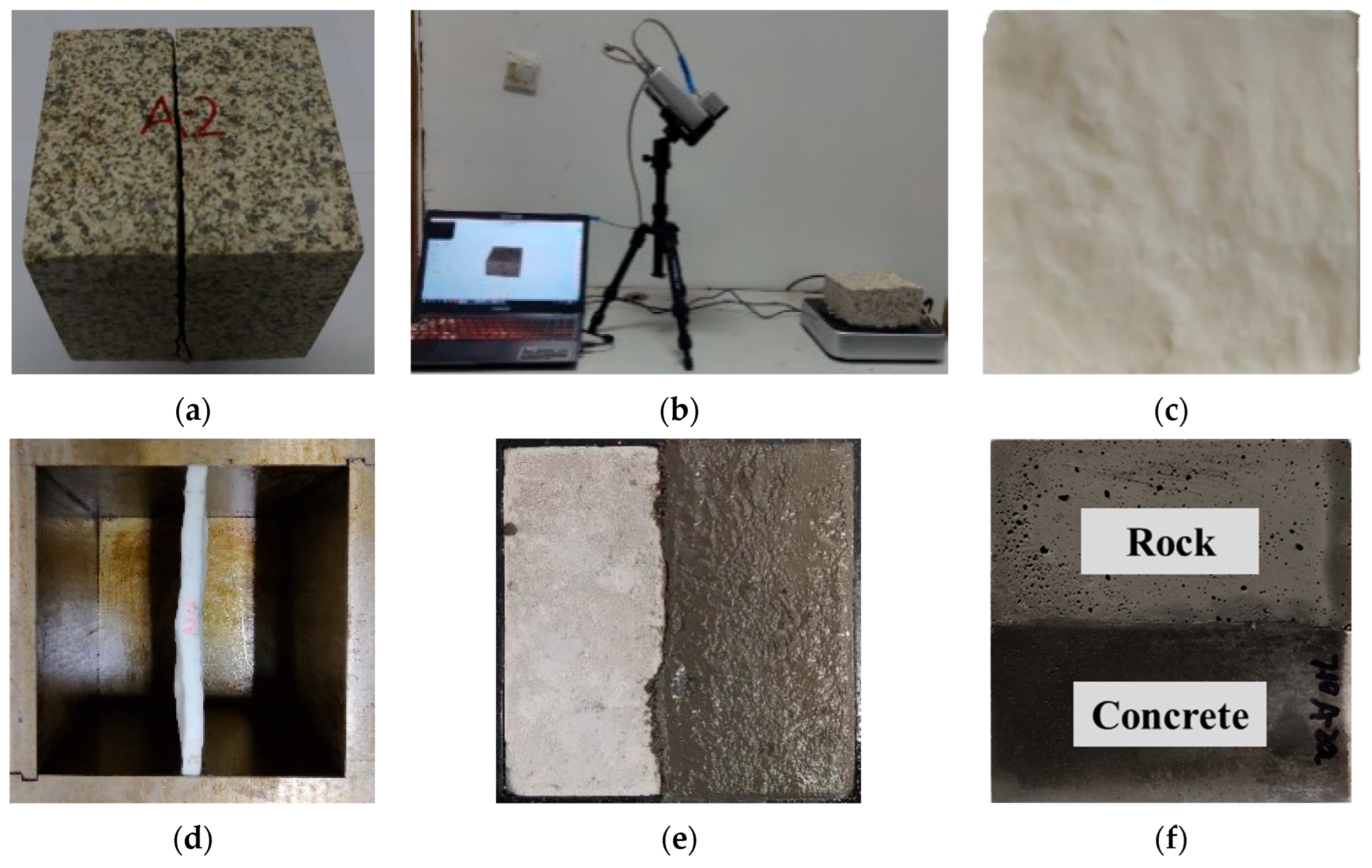
Figure 1. Production procedure for the wall rock–concrete contact samples. (a) Split rock samples. (b) Scanning of the split surface. (c) Three-dimensional printed contact surface sample. (d) Casting mold. (e) Casting with wall rock and lining similar materials. (f) Rock–concrete contact sample.
Water 16 02876 g001
Figure 2. CNL+CNS rock joint shear tester.
Water 16 02876 g002
Figure 3. Shear stress and displacement curves of the wall rock–lining contact surface under different normal stresses: (a) J1 and (b) J2.
Water 16 02876 g003
Figure 4. Shearing stiffness curves of specimens in the wall rock–lining contact surface.
Water 16 02876 g004
Figure 5. The FDM model for the shear simulation test of the wall rock–lining contact sample.
Water 16 02876 g005
Figure 6. Comparison between the numerical and laboratory shear test: (a) J1 and (b) J2.
Water 16 02876 g006
Figure 7. Three-dimensional model of the cross-fault tunnel.
Water 16 02876 g007
Figure 8. Initial faulting dislocation simulation.
Water 16 02876 g008
Figure 9. Wenchuan earthquake wave.
Water 16 02876 g009
Figure 10. Cross-fault tunnel under the combined action of faulting dislocation–seismic loading.
Water 16 02876 g010
Figure 11. Monitoring layout diagram of the cross-fault tunnel mechanical response.
Water 16 02876 g011
Figure 12. The plastic zone of the cross-fault tunnel model. (a) Initial dislocation distance of 5 cm. (b) Initial dislocation distance of 5 cm–seismic loading. (c) Initial dislocation distance of 30 cm. (d) Initial dislocation distance of 30 cm–seismic loading.
Water 16 02876 g012
Figure 13. Distribution of the plastic zone in the tunnel lining. (a) Initial dislocation distance of 5 cm. (b) Initial dislocation distance of 5 cm–seismic loading. (c) Initial dislocation distance of 30 cm. (d) Initial dislocation distance of 30 cm–seismic loading.
Water 16 02876 g013
Figure 14. The longitudinal deformation of the tunnel after a 30 cm faulting dislocation–seismic loading.
Water 16 02876 g014
Figure 15. Longitudinal seismic deformation of the tunnel excluding the initial dislocation distance.
Water 16 02876 g015
Figure 16. The longitudinal stress of the tunnel after a 30 cm faulting dislocation–seismic loading.
Water 16 02876 g016
Figure 17. The longitudinal seismic stress of the tunnel excluding the initial dislocation stress.
Water 16 02876 g017
Figure 18. The shear stress of the contact surface under the combined action of a 30 cm faulting dislocation–seismic loading. (a) Reverse fault. (b) Strike–slip fault. (c) Normal fault.
Water 16 02876 g018
Figure 19. The shear stress of the contact surface with different initial faulting dislocation distances. (a) The initial dislocation distance is 5 cm. (b) The initial dislocation distance is 30 cm.
Water 16 02876 g019
Figure 20. Time history curve of the tunnel relative displacement in the fault fracture zone. (a) Relative displacement of the top and bottom. (b) Relative displacement of the left and right side walls.
Water 16 02876 g020
Table 1. Parameters of the similar materials of the wall rock and lining.
MaterialsDensity
(kg/m3)
Elastic Modulus
(GPa)
Poisson’s RatioFriction Angle (°)Cohesion
(MPa)
Tensile Strength
(MPa)
The wall rock19901.220.19220.10.15
The lining232423.770.1854.93.162.0
Table 2. The mechanical parameters of the interface used in the numerical test.
Specimen Type σ n (MPa) τ (Tested)
(MPa)
k n
(MPa/mm)
k s
(MPa/mm)
τ (Calculated)
(MPa)
J10.50.851.530.200.85
1.01.213.050.261.21
1.51.624.580.381.60
32.849.150.262.86
53.3815.250.483.35
J20.51.041.920.211.20
1.01.693.840.311.69
1.51.845.760.271.84
32.8811.520.432.86
54.1219.200.584.07
Note: kn is the normal stiffness of interface, ks’’ is the shearing stiffness of the Coulomb interface model.
Table 3. Parameters of the cross-fault tunnel model.
MaterialsDensity
(kg/m3)
Elastic Modulus
(GPa)
Poisson’s RatioFriction Angle (°)Cohesion
(MPa)
Tensile Strength
(MPa)
Hanging wall26503.00.337.260.550.25
Foot wall23001.50.3328.80.50.2
Fault fracture zone21000.50.33220.10.15
Tunnel2500250.254.93.162.0
Disclaimer/Publisher’s Note: The statements, opinions and data contained in all publications are solely those of the individual author(s) and contributor(s) and not of MDPI and/or the editor(s). MDPI and/or the editor(s) disclaim responsibility for any injury to people or property resulting from any ideas, methods, instructions or products referred to in the content.