Article

A Study on the Optimal Speed Ratio of Rotating Annular Flume Based on the OpenFOAM Simulation

1
State Key Laboratory of Maritime Technology and Safety, Wuhan University of Technology, Wuhan 430063, China
2
National Engineering Research Center for Water Transport Safety, Wuhan University of Technology, Wuhan 430063, China
3
Zhejiang Scientific Research Institute of Transport, Hangzhou 311305, China
4
Changjiang Waterway Institute of Planning and Design, Wuhan 430040, China
5
Three Gorges Navigation Authority, Yichang 443000, China
*
Authors to whom correspondence should be addressed.
Water 2024, 16(16), 2354; https://doi.org/10.3390/w16162354
Submission received: 18 July 2024 / Revised: 19 August 2024 / Accepted: 21 August 2024 / Published: 22 August 2024
(This article belongs to the Section Hydraulics and Hydrodynamics)

Abstract

:
The rotating annular flume has been widely adopted to generate quasi-steady and uniform flow, thus serving for the investigation of sediment motion characteristics. This complex flow structure is significantly associated with the rotational speed ratio. The present study aims to explore the optimal speed ratio based on the OpenFOAM simulation. In this paper, the physical properties of a rotating annular flume with different speed ratios are investigated and analyzed in terms of bottom shear stress, turbulent velocity ratio, cross-sectional secondary flow, and vector field by interFoam, a built-in solver of the open-source CFD program OpenFOAM. The RNG k-epsilon model has been adopted to solve multiphase flow problems. The results demonstrate that the optimal speed ratio differs with the specific evaluation criterion. Given the uniform distribution of bottom shear stress, the turbulence velocity ratio, and the minimum secondary flow as the evaluation criteria, the corresponding optimal speed ratios are determined as 1.2, 1.7, and 1.7, respectively. The conclusion is generally consistent with the results derived by other scholars. Computational fluid dynamics programs have been proven as practical tools for investigating complex hydrodynamic characteristics. The present study shares useful insights into the optimal rotational speed ratio of a rotating annular flume. The OpenFOAM-based numerical model will provide guidance for experimental research using rotating annular flumes.

1. Introduction

The annular flume is one of the most important experimental facilities for studying hydrodynamic conditions and sediment movement characteristics. By adjusting the rotational speed ratio of the flume, a quasi-steady and uniform flow field distribution can be obtained. However, due to the special structure and operational principles of the annular flume, a cross-sectional secondary flow occurs, which presents a great impact on the dynamic processes of sediment initiation, settling, and flocculation. Therefore, the rotational speed ratio adjusting strategy has been widely adopted to minimize the secondary flow and facilitate the relevant studies [1]. The application of a rotating annular flume on sediment motion characteristics was initially started in the 1980s. Experimental studies on different research topics were carried out by related institutes, including the Tianjin Institute of Water Transport Engineering [2], Hohai University [3], Hangzhou University [4], the University of Palermo [5], the University of Plymouth [6], etc.
So far, the rotating annular flume has been widely utilized in various research fields. Tong et al. [7] used a two-way annular flume to simulate the dynamic process of water level and flow velocity variations and explored the characteristics of the secondary release of nitrogen from bed load in Lake Dongting. Baar et al. [8] used the annular flume to reveal the effect of lateral riverbed slope under riverbed flow conditions and analyzed the influence of various parameters on the lateral slope. Chen et al. [9] investigated the impact of bottom-bed chalk content on the scour characteristics of chalk-and-sand mixed beds based on experiments in an annular flume and highlighted the correlation between the bed load concentration and bottom shear stress.
With the aid of a rotating annular flume, a lot of research has been carried out on the mechanism of sediment movement. Li et al. [10] investigated the initiation, erosion, and deposition processes of viscous sediment using an annular flume. Zhou et al. [11] obtained the relationship between sediment deposition rate, sediment particle size, sediment concentration, and salinity through rotating annular flume experiments. Cloutier et al. [12] studied the impact of suspended sediment concentration (SSC) on fluid turbulence in an annular flume and explored the threshold SSC values. Wang et al. [13] collected sediment samples from the Jiangsu coast of China and reported the relationship between bed shear stress and suspended sediment concentration based on flume experiments. Neumeier et al. [14] introduced biological entities into the annular flume to reveal the impact of biota on the erosion of sediment beds. Thompson et al. [15] conducted sediment stability experiments in UK coastal waters and demonstrated the reliability and capability of the annular flume.
The annular flume has also been applied in studies of wave generation. Toffoli et al. [16] introduced the rotating annular flume to simulate an infinitely long straight flume; thus, the mechanism of wind force on rogue wave generation was thoroughly investigated, and useful insights into environmental management were provided. In another study, Gharabaghi et al. [17] applied the computational fluid dynamics (CFD) model Fluent to study the turbulent flow characteristics in a rotating circular flume at the National Water Research Institute (NWRI) in Burlington, Ontario. To improve the understanding of clayey sediment transport processes in riverine and lake environments, Gardner et al. [18] experimentally evaluated the phase wetting mechanism of oil–water flow and justified the effectiveness of the annular flume. Hong et al. [19] designed a cone–plate annular flume and explored the motion patterns of non-viscous homogeneous particles in laminar flow with the aid of CCD imaging and particle image velocimetry. Moreover, Huang et al. [20] explored the correlation between sediment concentration and bed shear stress through rotating annular flume experiments of sediment samples from the Yangtze River estuary, China.
The rotating annular flume consists of a shear ring and a rotating flume, and the apparatus is driven by two motors, thus yielding a generally uniform water flow field. The flow structure in the annular flume could be visualized and observed by adding tracer particles. An annular flume driven only by the shear ring will produce evident secondary flow, which results in an uneven distribution of the centrifugal force and pressure gradient [21,22]. By adjusting the rotation speed ratio of the shear ring and the annular flume, the secondary flow of the rotating annular flume can be minimized, and the uniformly distributed bottom shear stress can be obtained. Wang et al. [23] fitted the optimal rotational speed ratio curves and derived the plumbline flow velocity distribution law. Cao et al. [24] discussed the suitability of the traditional method in determining the optimal speed ratio and reported the optimal speed ratio through numerical simulations by ANSYS Fluent. Yang et al. [25] proposed a novel calculation formula for average bottom shear stress corresponding to the optimal speed ratio by means of computational fluid dynamics simulations. In addition, Yan et al. [26] explored the flow structure and shear stress distribution under different speed ratios and summarized the underlying variation mechanism. As an open-source CFD program with a large number of built-in solvers and unstructured meshing technology, OpenFOAM is capable of resolving the wall problems of multiphase flows and has been widely applied to investigate complex flow characteristics.
This paper is organized as follows: In Section 2, the specifications and model setup of the rotating annular flume through OpenFOAM are demonstrated in detail. In Section 3, the simulation results are presented, and discussions are provided in terms of bottom shear stress, turbulence velocity ratio, minimum secondary flow, and velocity vector field. The optimal rotation speed ratio is also determined and verified with the published literature. Finally, some preliminary conclusions are drawn in Section 4.

2. Numerical Model

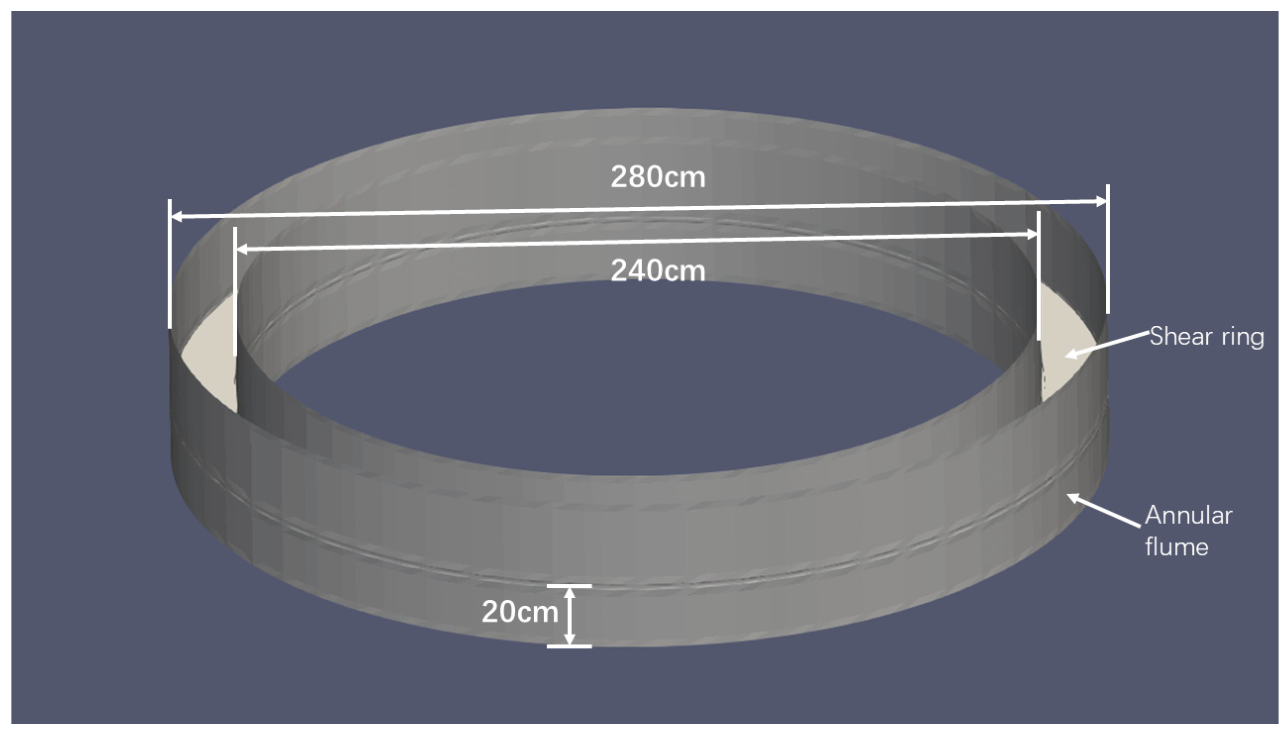
2.1. Specifications of the Rotating Annular Flume

Referring to the published literature [24], the annular flume at Hohai University, China, was adopted as the research objective. The inner and outer diameters of the annular flume are 240 cm and 280 cm, respectively. Both the shear ring and the annular flume can be manipulated separately with different speeds and rotational directions. The water depth in the flume is set constantly to 20 cm, and the schematic diagram of the rotating annular flume is shown in Figure 1.

2.2. Mathematical Model and Control Equations

Large eddy simulation (LES) and Reynolds-Averaged Navier–Stokes (RANS) are commonly adopted in resolving turbulence simulation problems. The basic idea of LES is to accurately solve the motions of all turbulence on a certain scale and capture the unsteady state points [27]. The Reynolds time-averaged (RTA) simulation is featured as a computationally efficient and low-mesh-quality requirement near the wall but is rarely utilized in the engineering fields [28]. The interFoam solver of OpenFOAM enables three flow simulation methods, namely Laminar flow, LES, and RANS. Although accurate numerical simulations could be derived from an LES, it would require significant computational resources. RANS provides reasonable results with lower computational costs and has been widely adopted in the numerical studies of flume hydrodynamics. Therefore, it is accepted to simulate the flow structure in a rotating annular flume.
Turbulence models mainly include the k-ω model and k-epsilon model. The k-ω model has been widely utilized while the model results are always sensitive to the initial conditions. The k-epsilon model is suitable for solving the non-separated compressible and incompressible fluids problems and is capable of simulating the internal motion of the complex flow field. Moreover, it can be readily implemented and has several variations for different research scenarios. In the present study, the RNG k-epsilon model is adopted and further modified for the dissipation rate calculation [29]. The model is a renormalization (Re-Normalisation Group) of the Navier–Stokes equations and outperforms the standard k-epsilon model for certain complex flow problems. The continuity and momentum equations are written as follows.
The continuity equation
ρ t + ρ u i x i = 0
in which ρ stands for the water density; u i represents flow velocity components; t represents time; and x i represents the coordinates.
The momentum equations
ρ u 1 t + div ρ u 1 u 1 = div μ grad u 1 p x 1 + S u 1 ρ u 2 t + div ρ u 2 u 2 = div μ grad u 2 p x 2 + S u 2 ρ u 3 t + div ρ u 3 u 1 = div μ grad u 3 p x 3 + S u 3
in which u i represents the velocity component in different directions (i = 1, 2, 3), corresponding to x, y, and z.
RNG k-epsilon model
ρ u i k x i = x j μ + μ t σ k k x j + P k ρ ε ρ Y k
( ρ ξ ) t + ρ u i ε x i = x j μ + μ t σ ε ε x j + C ε 1 ε k P k C ε 2 ρ ε 2 k ρ ε Y ε
in which k represents the turbulent kinetic energy; ε represents the dissipation rate of the turbulent kinetic energy; μ represents the kinetic viscosity; μ t represents the turbulent viscosity; σ k and σ ε represent turbulent shear stress and turbulent diffusion coefficient; P k is the turbulence generation term; Y k and Y ε are the turbulence generation terms; and C ε 1 and C ε 2 are empirical coefficients.
Turbulent viscosity model
μ t = ρ C μ K 2 ε
in which C μ is the empirical coefficient. In the present study, the coefficients are defined as C ε 1 = 1.42, C ε 2 = 1.68, C μ = 0.0845, η 0 = 4.377, and β = 0.012. All the above settings are determined within the OpenFOAM program. Detailed information can be found in the OpenFOAM user guide, webinars, and relevant articles (e.g., [24,26]).

2.3. Boundary Conditions
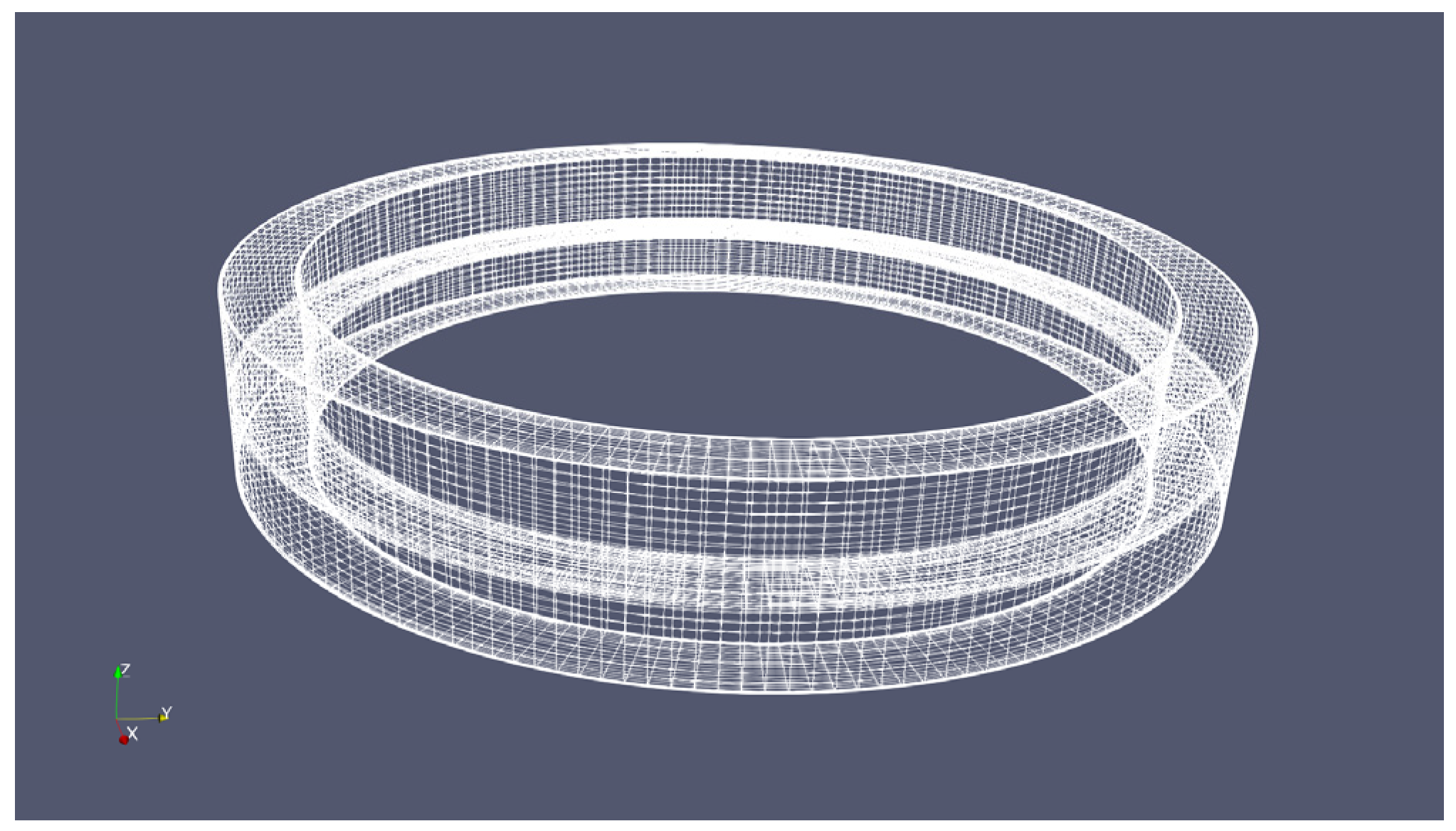
In order to solve the wall flow structure of the rotating annular flume accurately, the built-in solver interFoam of OpenFOAM is adopted. The shear ring is set as a solid domain with a thickness of 1 cm while the annular flume is defined as a solid domain consisting of the inner wall, outer wall, and bottom. The operation of the rotating annular flume is regarded as the relative motion of multiple bodies, and the sliding mesh technology is introduced in the present study. The wall rotation velocity condition is set for the shear ring, the velocity inlet and pressure outlet conditions are set for the fluid domain, and the pressure is set as a constant in the rotational domain. The viscosity coefficient is set as 0.001003 kg/m·s. Moreover, default values of the bed roughness are utilized, i.e., Ks = 0 mm and Cs = 0.5 mm. The time step is set as 0.001 s, and the numerical simulation is well converged with a residual of less than 1 × 10⁻⁶. The simulation parameters and boundary conditions are summarized in Table 1.

2.4. Gridding

The hexahedral mesh of the computational domain is generated by applying the built-in function module “snappyHexMesh”, and the distance from the first layer mesh point to the boundary is set up as 0.004 cm. The mesh scale factor in the vertical boundary direction is set as 1.2 and the number of mesh layers is 5. The total thickness of the boundary layer mesh is approximately 0.03 cm, which is consistent with the published literature [24]. The mesh generated by snappyHexMesh is illustrated in Figure 2.
A grid independence analysis was performed to determine optimal grid size and ensure the mesh quality. Three different schemes have been tested for a rotation speed ratio of 2.68. The vertical average flow velocity was extracted and compared with the experimental data in the literature [24]. A large error in the vertical average flow velocity was observed for a grid size of 4cm. The refined grid sizes of 2cm and 1cm yielded errors of 6.14% and 4.11%, respectively. It is worth noting that the computational expense increases substantially with a grid size of 1cm (i.e., Scheme C in Table 2). Therefore, the grid size of 2cm was eventually accepted in the present study. The results of grid independence analysis are tabulated below.

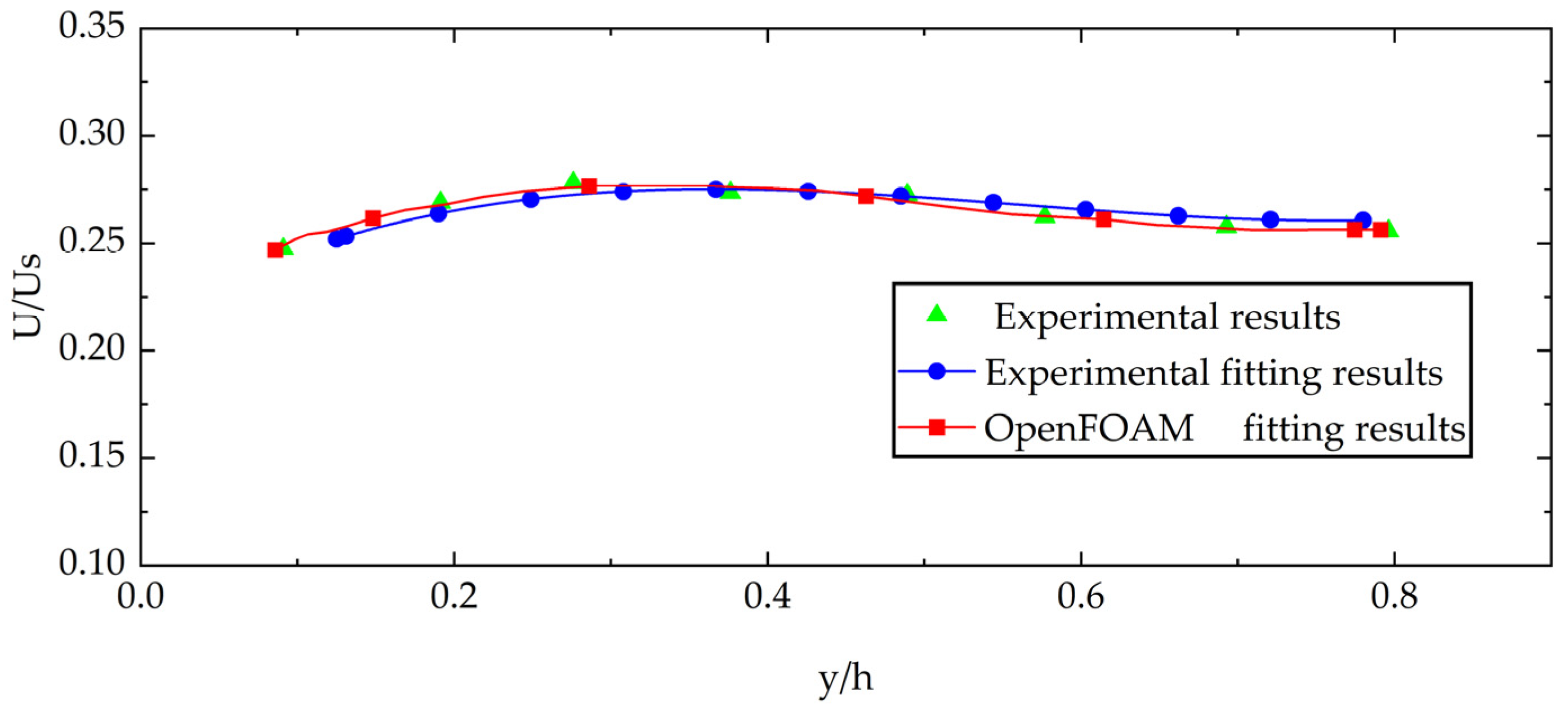
2.5. Model Validation

Numerical simulations were carried out against the published literature [24] for model verification. The rotation speeds of the shear ring and annular flume were set as 200 rpm (3.86 rad/s) and 124 rpm (1.42 rad/s), respectively. A comparison of the tangential flow velocity is demonstrated in Figure 3. The data show that the OpenFOAM-based simulation of flow velocity distribution is basically consistent with the experimental results [1] and Fluent-based numerical simulations [24]. The relative error between the numerical simulation results and the experiment data is less than 5% (about 3.16%), which further verifies the predictive capability of the OpenFOAM model in simulating the complex flow structure of the rotating annular flume.
It is noted that the numerical simulation of flow velocity distribution by OpenFOAM is basically consistent with the results of Fluent and physical experiments. The discrepancy between the OpenFOAM numerical simulation and the experimental data is approximately 3.16%. In view of the different meshing technologies applied in OpenFOAM and Fluent, the discrepancy in flow velocity noted in Figure 3 is considered acceptable. Owing to the non-slip conditions at the shear ring, high flow velocities are observed in the vicinity of the shear ring (as shown in Figure 3). The numerical simulations are carried out with different rotation speed ratios. It is found that although large flow velocity gradients exist in the regions near the shear ring, the flow velocity distribution in the central part of the annular flume remains relatively uniform. The distribution of dimensionless flow velocity and curve fitting is also presented in Figure 4. U represents the flow velocity at any point on the vertical line and US represents the velocity in the central part of the shear ring. y denotes the distance from the bottom of the annular flume at any point and h represents the water depth. The numerical simulation of the rotating annular flume is conducted with a rotation speed of 0.49 m/s (1.88 rad/s) and compared with the experimental results from the literature [23].
By adopting a polynomial fitting method, the following relationship is obtained.
U U S = a ( y h ) 3 + b ( y h ) 2 + c ( y h ) + d
Based on the numerical simulation results and experiment data, it can be concluded that the vertical flow velocity distributions across different rotational speed ratios and flume sizes exhibit similar trends. The coefficients in the fitted equation are associated with the rotational speeds of the shear ring and annular flume. In the present study, the coefficient of determination for the numerical simulation fitting is approximately 0.95, closely aligning with the literature [23]. Therefore, the distribution of vertical flow velocity in a rotating annular flume can be effectively described through the means of polynomial fitting, which validates the applicability of the OpenFOAM-based numerical model.

3. Results and Discussions

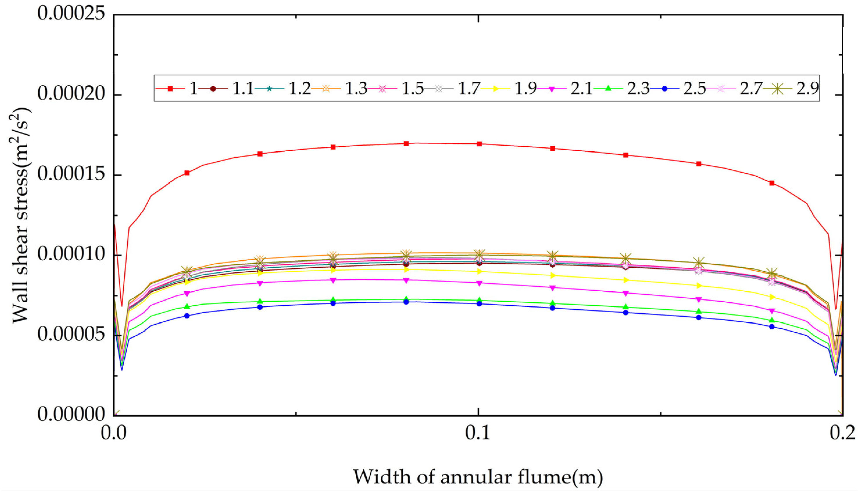
3.1. Bottom Shear Stress Distribution

The sediment motion characteristics are significantly correlated with the bottom shear stress distribution, which is caused by the flow velocity gradient near the wall. To facilitate experimental research on sediment movement characteristics, it is generally necessary to ensure the uniform distribution of bed shear stress so as to reveal the mechanism of sediment movement with different initial conditions. In the present study, the bottom shear stress is calculated and analyzed with the aid of a post-processing module of OpenFOAM. The shear stress is calculated as follows
τ w = ρ C μ k 1 / 2 y
where ρ is the fluid density and C μ is the empirical constant for turbulence modeling; k represents the turbulent kinetic energy; and y represents the distance from the wall. A total number of 12 sets of rotational speed ratios are investigated through OpenFOAM and the results are illustrated in Figure 5.
As shown in Figure 5, the wall shear stress in the middle region of the flume gradually increases when the rotation speed ratio increases. The shear stress appears to vary rapidly near the shear ring due to the constraint of the near-wall surface. As the rotational speed ratio of the annular flume is greater than 2.1, the maximum value of the bottom shear stress decreases. By calculating the variance of the bottom bed shear stress for different rotational speed ratios, the uniformity of bed shear stress distribution can be further evaluated, and the detailed results are provided in Figure 6.
Following Figure 6, it is concluded that a minimum variance in bottom bed shear stress appears when the rotational speed ratio is equal to 1.2. The shear stress distribution at the bottom is relatively uniform (as shown in Figure 5). Given the uniformity of bed shear stress distribution as the basic evaluation criterion, the optimal rotational speed ratio could be determined as 1.2, which is generally consistent with the conclusions (1.17) drawn in the literature [1]. It is noted that the shear stress variance decreases rapidly as the rotational speed ratio increases from 1.0 to 1.1. This is attributed to the enhanced vortex driven by the shear ring, which suppresses the vortex generated by the annular flume and results in a more uniform distribution of bottom bed shear stress. This trend agrees with the results presented by Cao et al. [24].

3.2. Turbulent Velocity Ratio
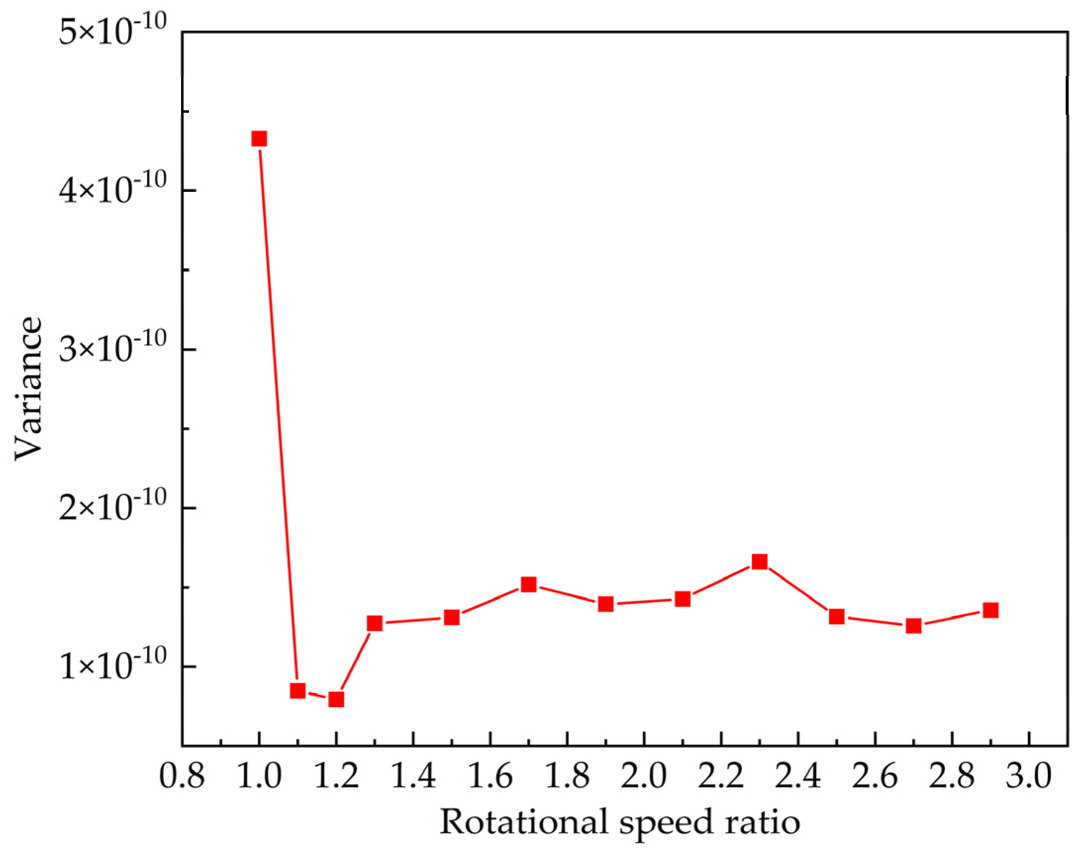
During the experimental operations of the annular flume, the shear ring and flume always rotate in opposite directions. Secondary flow could be generated in the flume, the presence of which would further affect the motion characteristics of sediment particles. Therefore, great efforts have been devoted to reducing the secondary flow by controlling the rotational speed ratio of the shear ring and annular flume. Cao et al. [24] pointed out that with the increasing speed ratio of the annular flume, the cross-sectional average flow velocity would increase with the rotational speed ratio. Thus, it is inappropriate to determine the optimal speed ratio based on the absolute magnitude of the secondary flow under different speed ratios. In the present study, the turbulent velocity ratio is introduced to represent the strength of the secondary flow, which is defined as follows.
R v = max ( v 2 + w 2 ) max u
where v is the radial velocity component; w is the vertical velocity component; and u is the tangential velocity component. The turbulent velocity ratio represents the ratio of the secondary flow to the main flow within the cross-section of an annular flume. This ratio reflects the intensity of the cross-sectional secondary flow for a given rotational speed ratio. The results of OpenFOAM-based numerical simulations for various rotational speed ratios are, therefore, presented in Figure 7.
The numerical simulations based on OpenFOAM show similar trends to those of Fluent-based modeling by Cao et al. [24]. A minor difference is found in the rotational speed ratio with regard to the minimum turbulent velocity ratio (OpenFOAM: 1.7; Fluent: 1.94). This is mainly attributed to the different turbulence models and mesh partitioning schemes adopted in the numerical simulations. Although the RNG k-epsilon model was adopted in the Fluent-based simulations, detailed information about parameter setting was absent in the literature [24]. Moreover, the mesh partitioning scheme differs from the present study. Overall, comparable features of turbulent velocity ratio variations have been reported by Gharabaghi et al. [17] and Cao et al. [24].

3.3. Secondary Flow

When the rotational speed ratio of the annular flume is fixed, the magnitude of the cross-sectional secondary flow can be calculated. By comparing the magnitude of the secondary flow for different rotational speed ratios, the evolutional features of the secondary flow can be further identified and discussed. The minimum secondary flow is defined as follows:
V f = min ( v 2 + w 2 )
where v represents the tangential velocity component and w represents the vertical velocity component. The results of the minimum secondary flow calculation based on OpenFOAM numerical simulations are shown in Figure 8. It is noted that the minimum cross-sectional secondary flow occurs at a rotational speed ratio of 1.7, which agrees with the conclusion drawn from the turbulent velocity ratio (as shown in Figure 7). The results demonstrate that the cross-sectional secondary flow is relatively small, and the turbulent kinetic energy intensity could be minimized as the rotational speed ratio is equal to 1.7 in the present study.
Given the rotational speed ratio equal to 1.0, a large vortex would be generated by the annular flume and result in great turbulent kinetic energy and maximum secondary flow (as shown in Figure 7 and Figure 8). The vortex in the vicinity of the outer wall is reduced as the rotational speed ratio increases. Both turbulent kinetic energy and maximum secondary flow would decrease. An optimal rotational speed ratio is thus obtained as 1.7. The flow velocity would increase as the rotational speed ratio keeps increasing. As a result, both turbulent kinetic energy and maximum secondary flow increase. It should be emphasized that the hydrodynamic features (e.g., turbulent kinetic energy and secondary flow) are associated with the flume properties and operating conditions.

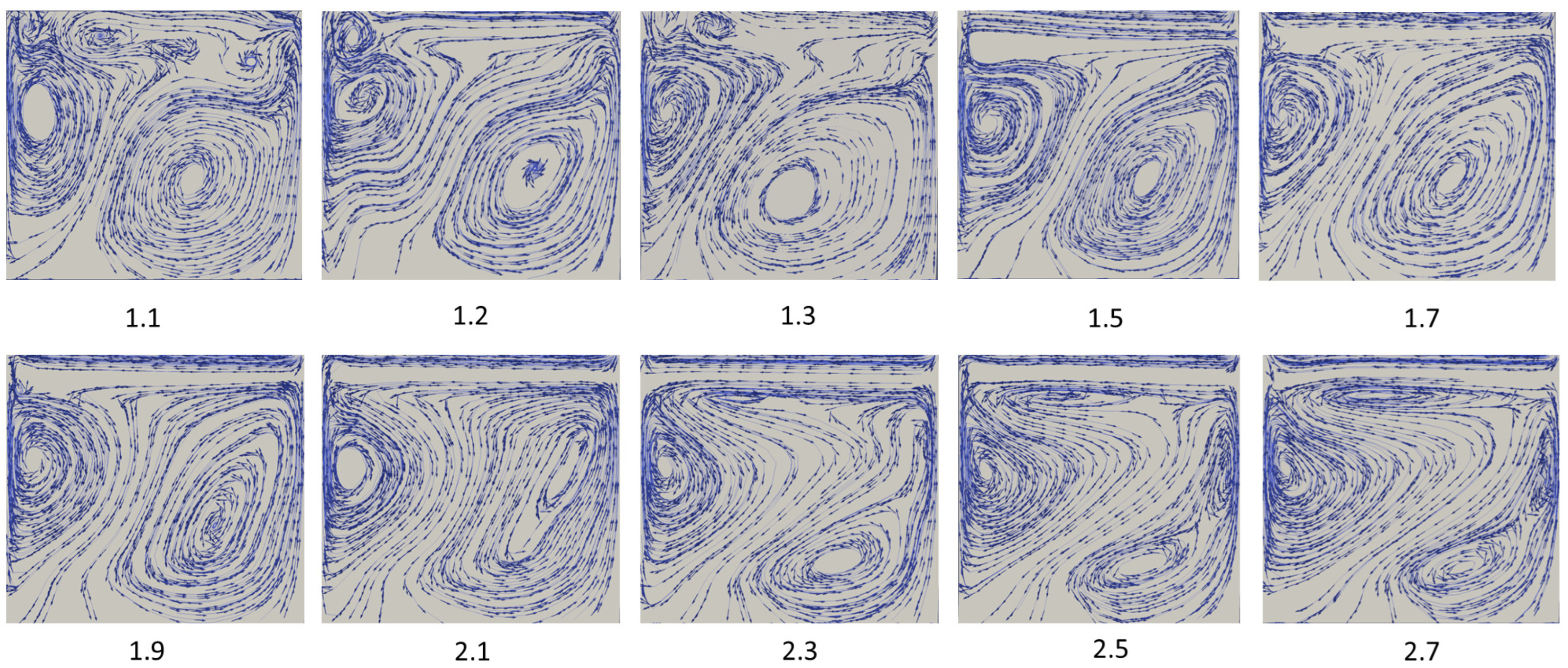
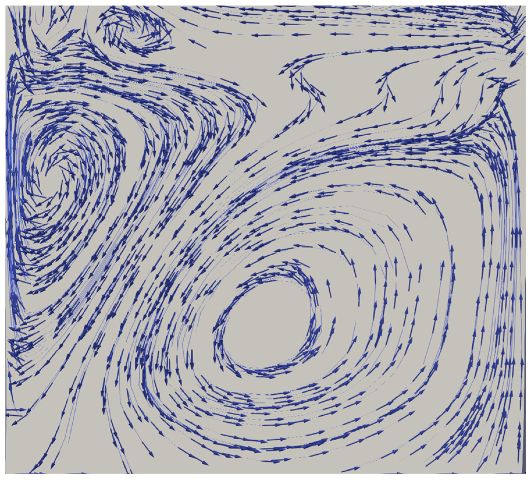
3.4. Cross-Sectional Velocity Vector Field

The two-dimensional velocity vector field is extracted with the aid of ParaView and presented for different rotational speed ratios in Figure 9. As the rotational speed ratio increases, different vortex patterns can be observed in the annular flume. When the rotational speed ratio is equal to 1.3, the upper vortex moves outward while the lower vortex is reduced. The flow velocity distribution at the bottom of the flume becomes relatively uniform. Given that the rotational speed ratio increases gradually, the vortex generated by the shear ring would be further enhanced. The cross-sectional flow patterns (as shown in Figure 9) would exert a significant impact on the motion characteristics of sediment particles. A detailed flow velocity field for a speed ratio of 1.3 is presented in Figure 10.
As shown in Figure 10, the flow circulation may push the sediment outward first and then bring it backward. The lower circulation is distributed more uniformly at the flume bottom, leading to a relatively uniform sedimentation. Given a rotational speed ratio larger than 1.3, the vortex generated by the rotating shear ring will dominate the cross-sectional flow field and more sediment particles would be expected to settle along the inner wall. Therefore, a rational speed control strategy needs to be developed to minimize the secondary flow and unify the cross-sectional flow field.

4. Conclusions

The rotating annular flume is one of the commonly used experimental instruments of sediment movement characteristics. However, the flow structure differs with its operational modes (i.e., rotational speed ratio) and flume properties. In this paper, the computational fluid dynamics software OpenFOAM has been introduced to model flow structure and obtain the optimal speed ratios corresponding to different evaluation criteria. Some preliminary conclusions are provided as follows:
  • OpenFOAM has highly customizable attributes, diversified built-in solvers, and complete post-processing function modules. OpenFOAM-based numerical simulations of flow structure have been compared with the published literature and experimental data, which further validate the capability of OpenFOAM in solving complex flow problems.
  • The rotational speed ratio is identified as a key factor influencing the cross-sectional velocity vector field of rotating annular flumes. With regard to the uniform distribution of bottom shear stress, turbulent velocity ratio, and minimum secondary flow, the optimal speed ratios are determined as 1.2, 1.7, and 1.7, respectively. This conclusion is generally consistent with the published literature and experiment data.
  • The present study highlighted the predictive capability of OpenFOAM. The optimal rotational speed ratios determined by numerical simulations would provide a reference for the implementation of a rotating annular flume. Moreover, the OpenFOAM-based numerical model could be extended by incorporating a material transport module (e.g., Lagrangian particle method); thus, the sediment motion characteristics could be further investigated.

Author Contributions

Conceptualization, S.C. (Sijin Chen) and Z.J.; methodology, S.C. (Sijin Chen); validation, S.C. (Sijin Chen); formal analysis, S.C. (Shijun Chen) and Z.J.; investigation, S.C. (Shijun Chen), Z.Y. and Z.J.; data curation, S.C. (Shijun Chen) and H.S.; writing—original draft preparation, S.C. (Sijin Chen); writing—review and editing, S.C. (Sijin Chen) and Z.J.; supervision, Z.J.; funding acquisition, Z.J. All authors have read and agreed to the published version of the manuscript.

Funding

This research was funded by the National Natural Science Foundation of China (grant numbers 52071250 and 51709220).

Data Availability Statement

The data presented in this study are available on request from the corresponding author. The data are not publicly available due to privacy.

Conflicts of Interest

The authors declare no conflicts of interest.

References

  1. Booij, R. Measurements of the flow field in a rotating annular flume. In Communications on Hydraulic and Geotechnical Engineering; Report No. 1994-02; Technische Universiteit Delft: Delft, The Netherlands, 1994; Available online: http://resolver.tudelft.nl/uuid:431193bc-8cfb-46ce-81fd-5034941b0769 (accessed on 20 June 2024).
  2. Feng, X. Research on the mechanism and application of annular flume. J. Waterw. Harb. 1998, 03, 7–11. [Google Scholar]
  3. Cao, K.; Lv, B.; Shao, Y. Research progress of annular flume technology. Appl. Mech. Mater. 2013, 256, 2498–2508. [Google Scholar] [CrossRef]
  4. Wang, L. The design of the combined circulating water tank and its characteristics. J. Hangzhou Univ. 1988, 15, 227–233. [Google Scholar]
  5. Ferro, V. Simple flume with a central baffle. Flow Meas. Instrum. 2016, 52, 53–56. [Google Scholar] [CrossRef]
  6. James, P.; Jones, T.; Stewart, D. Numerical and experimental studies of annular flume flow. Appl. Math. Model 1996, 20, 225–231. [Google Scholar] [CrossRef]
  7. Tong, Y.; Liang, T.; Wang, L.; Tian, S. Characteristics of nitrogen release from Lake Dongting sediments under variable water level and velocity in the two-way annular flume. J. Lake Sci. 2016, 28, 59–67. [Google Scholar]
  8. Baar, A.W.; de Simt, J.; Uijttewaal, W.S.; Kleinhans, M.G. Sediment transport of fine sand to fine gravel on transverse bed slopes in rotating annular flume experiments. Water Resour. Res. 2018, 54, 19–45. [Google Scholar] [CrossRef]
  9. Chen, Y.; Qiao, Z.; Xv, C.; Yao, P. Influences of sediment composition on scour of silt-sand mixture bed. Int. J. Sediment Res. 2021, 46, 1–8. [Google Scholar]
  10. Yv, L.; Jing, Y. Experimental study on cohesive sediment in ring channel. J. Waterw. Harb. 2005, 26, 79–81. [Google Scholar]
  11. Zhou, J.J.; Zhang, C.K.; Jing, Y. Experimental research on cohesive free sediment of the South Passage in the Yangtze estuary by two- way annular flume. Yangtze River 2008, 39, 16. [Google Scholar]
  12. Cloutier, D.; Lecouturier, M.N.; Amos, C.L.; Hill, P.R. The effects of suspended sediment concentration on turbulence in an annular flume. Aquat. Ecol. 2006, 40, 555–565. [Google Scholar] [CrossRef]
  13. Wang, Y.W.; Yu, Q.; Gao, S. Relationship between bed shear stress and suspended sediment concentration: Annular flume experiments. Int. J. Sediment Res. 2011, 26, 513–523. [Google Scholar] [CrossRef]
  14. Neumeier, U.; Lucas, C.H.; Collins, M. Erodibility and erosion patterns of mudflat sediments investigated using an annular flume. Aquat. Ecol. 2006, 40, 543–554. [Google Scholar] [CrossRef]
  15. Thompson, C.; Couceiro, F.; Fones, G.; Amos, C. Shipboard measurements of sediment stability using a small annular flume—Core Mini Flume (CMF). Limnol. Oceanogr. Methods 2013, 11, 604–615. [Google Scholar] [CrossRef]
  16. Toffoli, A.; Proment, D.; Salman, H.; Monbaliu, J.; Frascoli, F.; Dafilis, M.; Stramignoni, E.; Forza, R.; Manfrin, M.; Onorato, M. Wind generated rogue waves in an annular wave flume. Phys. Rev. Lett. 2017, 118, 144503. [Google Scholar] [CrossRef] [PubMed]
  17. Gharabaghi, B.; Inkratas, C.; Krishnappan, B.G.; Rudra, R.P. Flow characteristics in a rotating circular flume. Open Civ. Eng. J. 2007, 1, 1. [Google Scholar] [CrossRef]
  18. Gardner, T.; Paolinelli, L.D.; Nesic, S. Study of water wetting in oil-water flow in a small-scale annular flume. Exp. Therm. Fluid Sci. 2019, 102, 506–516. [Google Scholar] [CrossRef]
  19. Hong, A.; Wang, Z.; Zhao, T. Development of cone-plate annular flume and its application on onset motion of particles. Trans. Chin. Soc. Agric. Eng. 2015, 31, 77–82. [Google Scholar]
  20. Huang, W.; Liu, Y.K.; Wu, H.L.; Wan, Y.Y. The incipient motion features of sediment from Yangtze estuary: Annular flume experiments. Sci. Rep. 2017, 7, 13285. [Google Scholar]
  21. Abduo, S.S.; Elmoustafa, A.M.; Salam, M.S.A. Study of counteracting the secondary flow in open channel bends. Ain Shams Eng. J. 2021, 12, 2425–2433. [Google Scholar] [CrossRef]
  22. Yang, Z.; Baptista, A.; Darland, J. Numerical modeling of flow characteristics in a rotating annular flume. Dynam Atmos. Oceans 2000, 31, 271–294. [Google Scholar] [CrossRef]
  23. Wang, J.; Zhou, J.J.; Zhang, C.K. Experimental study on velocity distribution of two-direction rotating annular flume. J. Sediment Res. 2014, 5, 32–37. [Google Scholar]
  24. Cao, K.; Lv, B.; Shao, Y. Study on best rotating ratio of annular flume. J. Waterw. Harb. 2016, 37, 484–489. [Google Scholar]
  25. Yang, S.H.; Im, I.T.; Hwang, K.N.; Cho, Y.S.; Ryn, H.R. A numerical study on optimal rotation ratio and bottom shear stress in the counter-rotation mode of an annular flume. J. Hydro Environ. Res. 2015, 9, 473–481. [Google Scholar] [CrossRef]
  26. Yan, J.; Zhang, L.T.; Xv, L.J.; Chen, S.N.; Peng, G.H.; Wang, M. Three-Dimensional Numerical Simulation of Flow Structure in Annular Flume Based on CFD Study of Water. Water 2023, 15, 651. [Google Scholar] [CrossRef]
  27. Fröhlich, J.; Von Terzi, D. Hybrid LES/RANS methods for the simulation of turbulent flows. Prog. Aerosp. Sci. 2008, 44, 349–377. [Google Scholar] [CrossRef]
  28. Iaccarino, G.; Ooi, A.; Durbin, P.; Behnia, M. Reynolds averaged simulation of unsteady separated flow. Int. J. Heat Fluid 2003, 24, 147–156. [Google Scholar] [CrossRef]
  29. Yakhot, V.; Orszag, S.; Thangam, S.; Gatski, T.; Speziale, C. Development of turbulence models for shear flows by a double expansion technique. Phys. Fluids 1992, 4, 1510–1520. [Google Scholar] [CrossRef]
Figure 1. Schematic diagram of the rotating annular flume.
Water 16 02354 g001
Figure 2. Grid division of the rotating annular flume.
Water 16 02354 g002
Figure 3. Comparison between numerical simulations and experiment data.
Water 16 02354 g003
Figure 4. Distribution of the dimensionless flow velocity for numerical simulations and experiment data.
Water 16 02354 g004
Figure 5. Wall shear stress distribution for different rotational speed ratios.
Water 16 02354 g005
Figure 6. Variations in shear stress variance for different speed ratios.
Water 16 02354 g006
Figure 7. Comparison of turbulent velocity ratio between OpenFOAM and Fluent simulations.
Water 16 02354 g007
Figure 8. Variations in cross-sectional secondary flow for different speed ratios.
Water 16 02354 g008
Figure 9. Cross-sectional velocity vector field for different speed ratios.
Water 16 02354 g009
Figure 10. Cross-sectional velocity vector field for speed ratio 1.3.
Water 16 02354 g010
Table 1. Summary of model parameters and boundary conditions.
Model DomainUPTurbulent ViscositykEpsilon
Shear ringrotatingWallVelocityfixedFluxPressurenutUWallFunctionkqRWallFunctionepsilonWallFunction
Annular flumenoSlipfixedFluxPressurenutUWallFunctionkqRWallFunctionepsilonWallFunction
Table 2. Results of grid independence analysis.
SchemeGird Size/cmRotation Speed RatioError
A42.6835.71%
B22.686.14%
C12.684.11%
Disclaimer/Publisher’s Note: The statements, opinions and data contained in all publications are solely those of the individual author(s) and contributor(s) and not of MDPI and/or the editor(s). MDPI and/or the editor(s) disclaim responsibility for any injury to people or property resulting from any ideas, methods, instructions or products referred to in the content.

