Abstract
A comprehensive two-dimensional (2D) time-domain numerical model is established to investigate the interaction of irregular waves and submerged structures with different sections. The model specifically focuses on the dual-lane submerged floating tunnel (SFT) designs, encompassing elliptical, twin-circular, and round rectangular sections. For the hydrodynamic analysis, we adopt the second-order potential flow theory, while for the mooring line simulations, we employ the slender rod theory, taking into account the entire hydrodynamic load acting on it. In the coupled dynamic analysis, the fourth-order Adams–Bashforth–Moulton method, Newmark-β method, and Newton–Raphson iteration scheme are utilized for the coupled motion equation of the floating body and the dynamic equation of the mooring riser system. Experimental free decay tests are conducted to determine the damping coefficients of various section shapes in different directions. Our analysis delves into the detailed motion responses and mooring tensions of the SFTs with different section forms under irregular waves. We compare and contrast these responses in both time and frequency domains, particularly focusing on movement trends. The elliptical section structure emerges as the most stable design based on our comparisons. These findings provide valuable insights for the selection of optimal section shapes for dual-lane SFTs.
1. Introduction
A submerged floating tunnel (SFT) is a new type of traffic mode, which uses different support forms to connect the main body of the tunnel and the seabed by balancing the ratio between buoyancy and gravity, so that it can be suspended in the sea, also known as Archimedes Bridge. The continuous innovation and development of transportation modes provide more platforms for new structures. Compared with general transportation modes, the SFT can cross the strait, bay, and other water with limited environmental conditions, saving time and space. Its advantages are obvious, and scholars from all countries carried out extensive research on the SFT. Xiang et al. [1], Geng et al. [2], and Zhang et al. [3] all reviewed the progress of research on the dynamic response of SFTs under a variety of loads and made an outlook on the future research direction. The SFT may bear a variety of loads as new underwater vehicle engineering in the future. Xiang et al. [4] designed and analyzed an SFT experimental model to investigate the dynamic behavior of the SFT under moving vehicle load, and discussed the effects of a cable and vehicle with different parameters of the SFTs. Jin et al. [5] presented the optimization process of a tunned mass damper (TMD) to mitigate the lateral motions and mooring tensions of an SFT under seismic excitations, and demonstrated that TMD played an important role in SFT vibration control. Wu et al. [6] experimentally investigated the dynamic behavior of SFT subjected to the combined action of an earthquake, wave, and current, which had theoretical and engineering importance for the prevention and control of hazards of design for the SFT located in a complicated ocean environment. For a structural force analysis of the SFT, Won et al. [7] experimentally analyzed the bending behavior of module joints in SFT to evaluate the safety for the bending deformation. Then, the structural torsional behavior of module joints of a steel composite hollow RC for the SFT was studied experimentally and analytically, and they evaluated the failure modes and torsional behavior characteristics with the connection variables of this joint [8]. Recently, they analyzed the vibration characteristics of an SFT using the free vibration analysis and time-domain analysis techniques, and demonstrated that the SFT has excellent self-vibration control [9]. Wu et al. [10] proposed the semirigid and semiflexible joint structure of SFTs based on the similar structure of immersed tunnel joints and very large floating structure (VLFS) connectors, and studied the nonlinear characteristics under a combined load (axial force and bending moment) with mathematical analyses and numerical simulations. Kwon et al. [11] investigated a digital-twin-assisted artificial neural network (ANN) model that can predict the dynamic and structural behaviors of an SFT using numerical accelerometers and angle sensors sparsely distributed along its length. For possible damage to the cable, Min et al. [12] proposed an advanced damage detection method for the tethers of SFT based on the convolutional neural network, and the proposed model could be effectively used for a submerged structure based on the feasibility study. Shao et al. [13] presented a novel sensitive damage detection approach for the main tube and the tether system of the SFT in the context of statistical pattern recognition to analyze the vibrating behaviors induced by currents acting upon both the tube and the tethers by making use of the time-domain force and displacement series.
SFT has more advantages in large-span deep-sea environments. Generally, its submergence depth is not enough to ignore surface waves’ influence. Especially in extreme sea conditions, wave load will become an important load to control the safe operation of SFT. Liu et al. [14] investigated the hydrodynamic properties of a general tube segment of an SFT under different constraints and wave loading conditions. The amplitude of the excitation force and motion transfer functions as well as the motion spectra under specified wave spectra were validated by using the experimental data. Xiang and Yang [15] aimed at the global spatial impact response of the SFT by taking into consideration the nonlinear hydraulic resistance, and studied the factors such as the anchorage stiffness, inclined angle of the cable, buoyancy–weight ratio, and hydraulic resistance, which affect the impact response. Sharma et al. [16] proposed a coupled model involving a submerged floating sea tunnel and a bottom-mounted submerged porous breakwater to study wave reflection and transmission characteristics of a porous breakwater and its role in mitigating wave forces on a tunnel. At this stage, most of the research on SFTs has been simplified to a circular cross-sectional shape, whereas in the context of practical engineering, SFTs require at least two lanes to meet the traffic demand. For this reason, the dynamic response characteristics of SFTs with other cross-sectional shapes need to be studied urgently. Faggiano et al. [17] described the conceptual design of an SFT for crossing the Gulf of California linking the mainland of the northwest of Mexico to the Baja California peninsula; the design contained a variety of section forms. Jin et al. [18] analyzed the hydrodynamic characteristics of three different cross-sections (circular, elliptical shape, and twin-circle shape) for different environmental parameters, compared the wave excitation forces, and added masses and radiation damping to which the structure was subjected. Liu et al. [19] similarly analyzed the kinematic response of SFTs with four cross-sectional shapes under different mooring inclination angles to provide a reference for the selection of cross-sectional shapes and mooring inclination angle design. Chen et al. [20] presented a numerical model for analyzing the nonlinear interaction between the moored SFT and surface waves, and compared with two laboratory experiments for validating. The hydrodynamic model was then utilized to simulate the wave–structure interaction of the prototype SFT design for Funka Bay, Hokkaido, located in Japan. Won et al. [21] described the hydrodynamic behavior of SFTs with dual circular sections under irregular waves, and the influences of the buoyancy–weight ratio (BWR), current, spacing of tunnel bodies, and wave steepness were analyzed on the behavioral characteristics. Deng et al. [22,23,24] considered a potential pontoon-supported curved SFT designed for crossing Sognefjorden, which consisted of two identical tubes. Experimental and numerical investigations were carried out for several topics, and the simulation of the wave- and flow-induced load effects provides a good reference for the design of SFTs. Shivakumar and Karmaker [25] analyzed the wave interaction with an SFT of two different shapes (rectangular and circular) in the presence of a submerged rubble mound breakwater using the Multi-Domain Boundary Element Method.
The current research on SFT mainly focuses on two research methods, i.e., the physical model test and mathematical simulation. From the perspective of the research object, it mainly focuses on the overall structure and hydrodynamic response of SFT at the macro-level, as well as the safety of SFT materials and structures at the micro-level. Due to the lack of practical applications, many researchers started with various research concentrating on exploring the influencing factors of SFT under different conditions and promoting its practical application. To get closer to practical applications, this paper focuses on the investigation of hydrodynamic characteristics of two-lane SFT with different section forms, and combines experiments to compensate for the shortcomings of potential flow theory that cannot consider the viscosity. In this paper, the motion responses and anchor tensions are investigated under the irregular waves, and the detailed statistical analysis of the calculated results is carried out both in time and frequency domains. The results can provide support for the selection of SFT with a two-lane section in the future.
2. Basic Method
2.1. Wave–SFT–Mooring Interaction Numerical Model
Since the SFT length is much greater than the section size, the right-handed 2D coordinate system is established to investigate the interaction between waves and the SFT, as shown in Figure 1, which also contains the identification of the movement in each direction. The calculation of the hydrodynamic part on the structure is based on the potential flow theory, and the higher-order boundary element method (HOBEM) is applied to discrete body surface and water surface, the calculation of the mooring line is based on the slender rod theory, and the finite element method is used here. The wave–SFT–mooring interaction system is coupled by matching conditions at the fairleads in the time domain.
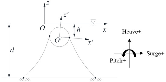
Figure 1.
Sketch of defined coordinate system and movement.
The SFTs are usually large in their own dimensions in order to meet the requirements for traffic passage, and their presence would have an impact on the wave field, so the 2D hydrodynamic mathematical model of wave–SFT interaction is based on Radiation-Diffraction theory. The governing equation is based on the Laplace equation, and corresponding boundary conditions are also satisfied.
where ϕ is velocity potential, d is the water depth, n is the instantaneous unit normal vector pointing out the fluid, V is the SFT velocity in the fixed coordinate, g is the gravity acceleration, and η is the wave elevation. HOBEM is applied to discretize the surface of the object and the free water surface; Jin et al. [26] have discussed the relevant theory in detail, and at the same time, the model validation about the hydrodynamic part was also included in the above reference [26].
For the dynamic analysis of mooring lines, the slender rods theory is used and the finite element method is used to implement the developed theory into a numerical model. The relevant theoretical assumptions, governing equations, and hydrodynamic load calculation method are shown in Appendix A.1.
The mooring dynamic program is then coupled to the hull dynamics program through the matching conditions at the fairleads. The motion equations for the hull and the numerical implementation containing the fourth-order Adams–Bashforth–Moulton method, Newmark-β method, and Newton–Raphson iteration scheme are shown in Appendix A.2.
In the actual sea environment, waves are composed of many waves with different amplitudes, frequencies, and phases. The randomness of wave sequences is strong. The Jonswap spectrum is applied to simulate the series of irregular waves. Assuming that Ai, ωi, ki, and εi and Aj, ωj, kj, and εj are the wave amplitude, angular frequency, wave number, and wave phase of two arbitrary waves, the expressions of second-order wave velocity potential and wave elevation are shown below.
where each physical quantity can be expressed as
2.2. Damping Coefficient Experiments
To ensure the accuracy of the calculation results, a series of physical model tests were carried out to determine the damping coefficients of different shapes in all directions. The physical model experiments were carried out in the wave flume of Tianjin Research Institute of Water Transport Engineering (TIWTE). The flume is 46 m long, 0.5 m wide, and 1.2 m deep. The SFT element model was manufactured from plastic and concrete. The two mooring lines were connected with springs and tighteners. The model scale was 100 in the experiment for obtaining the damping coefficient. Based on the research conducted by other scholars [26], the damping coefficient of a submerged structure is dependent on its shape in the water, thereby rendering the anchoring system and subsequent calculations not entirely consistent. The water depth d was 1.00 m, and submerged depth h was 0.30 m. The motion responses of the SFT were measured synchronously by an electromagnetic motion system. The transmitter was fixed on the wooden frame (without affecting the magnetic field) 0.4 m above the assembly and emitted space magnetic field as the origin of the reference frame. Meanwhile, the receiver was attached at the top center of the assembly to position and track the six real-time DOFs of the rigid body by continuously processing the magnetic signal. The accuracy of the equipment was ±1 mm for translations and ±0.4 deg for rotations. All the data were sampled in 120 Hz. The test photos in the experiments are shown in Figure 2, which contains the round rectangular (RR), twin-circular (TC), and elliptical (EL) sections in still water. Figure 3, Figure 4 and Figure 5 show the free decay curves of each section in the wave flume.
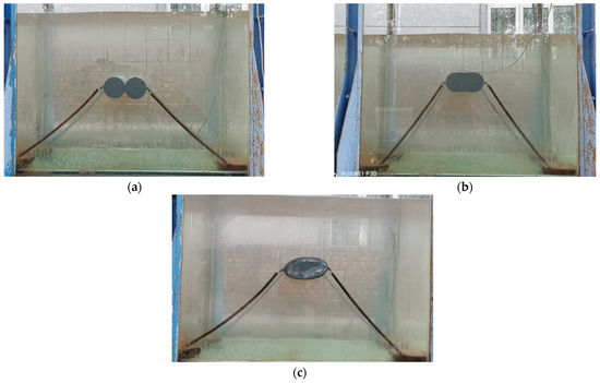
Figure 2.
Model photos in the experiments: (a) twin-circular section, (b) elliptical section, (c) round rectangular section.

Figure 3.
Free decay curves of twin-circular section SFT in still water: (a) in surge direction; (b) in heave direction.

Figure 4.
Free decay curves of round rectangular section SFT in still water: (a) in surge direction; (b) in heave direction.

Figure 5.
Free decay curves of elliptical section SFT in still water: (a) in surge direction; (b) in heave direction.
The free motion equation of SFT in the still water is
where [a], [b], and [K] are main diagonal elements of the added mass matrix, radiation damping, and stiffness matrix.
Define and , and Equation (13) can be written as follows:
whose solution is
where ξA0 is initial displacement, is the damping coefficient, and is the natural frequency considering the water damping. is the dimensionless decay coefficient.
According to the decay curve, the motion amplitude decays exponentially over time, and the nth peak value of motion is recorded as ξAn. Therefore, the expression of the dimensionless decay coefficient is
After obtaining the viscous damping, the motion response can be revised by the damping force, which is opposite the direction of movement.
The added mass and radiation damping of SFT with different section forms can be obtained by the potential flow method in the frequency domain (Jin et al. [18]).
The damping coefficients of the different section forms are calculated by the free decay curves; the results are shown in Table 1.

Table 1.
The damping coefficients of the different section forms.
3. Calculation and Discussions
3.1. Parameter Introduction
Tension-leg-type SFT is composed of a submerged tunnel structure and tension leg system. In the actual structural design of SFT, in order to satisfy the design concept of dual lanes, it is crucial to select a suitable dual-lane SFT. To deeply explore the hydrodynamic characteristics of dual-lane SFT with different section forms, this paper compares the motion response and mooring line tension of SFT with different section forms.
Figure 6 shows a detailed sketch of three different cross-section forms. The submerged depth, up-wave width, cross-section area, buoyancy–weight ratio (BWR = 1.20) and pretension of the SFT of each section are the same. In this paper, the twin-circular section is fixedly connected by two circular section pipes, the upper and lower parts are fixed by the beam, and the tension leg connects the middle point of the beam and the seabed. Different from the twin-circular section, the two sides of the ear section are semicircles with a diameter of 30 m, and the upper and lower parts are connected by straight walls. For the tension-leg-type SFT, four symmetrically arranged inclined mooring lines are set to limit the horizontal and vertical displacement of the structure. The specific parameters of the mooring system are shown in Table 2.
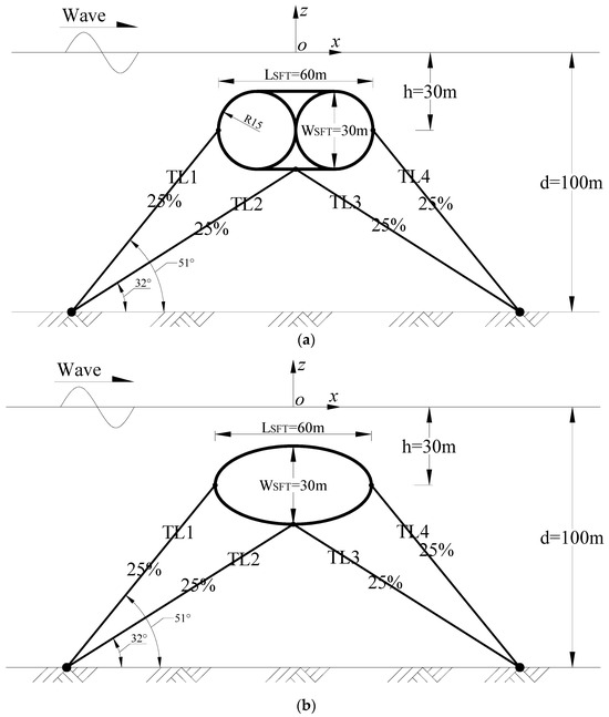
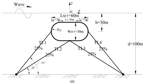
Figure 6.
Sketch of three types’ section forms’ SFT in numerical model: (a) twin-circular section, (b) elliptical section, (c) round rectangular section.

Table 2.
Basic parameters of tension leg mooring system.
Table 3 shows the number of elements of the numerical grid for three types’ cross-sectional SFTs. In order to study the hydrodynamic characteristics of dual-lane SFTs with different cross-sections, the number of water surface grids for each of the three cross-sections is about 3 m, which is satisfied with one twentieth of the wavelength. Thus, the second-order hydrodynamic characteristics of the SFT can be accurately calculated. The water surface line is taken at 600 m along both sides of the x-axis from the coordinate origin. The total number of water surface grids is 400. Figure 7 presents a schematic representation of the mesh applied to the surface of a twin-circular section SFT and a truncated section of the water surface.

Table 3.
Number of elements of the numerical grid in the numerical simulation.

Figure 7.
Mesh sketch of water surface and SFT surface in numerical simulation.
3.2. Motion Response Analysis of SFT with Different Section Forms
In this paper, the irregular waves act on three types of SFT sections. The significant wave heights are all 4.0 m; the significant wave periods are from 6.0 s to 14.0 s. The comparisons of the wave power spectra are shown in Figure 8. The results show that the energy of long-period waves is more concentrated, and the energy is greater than that of short-period waves with the same wave height.
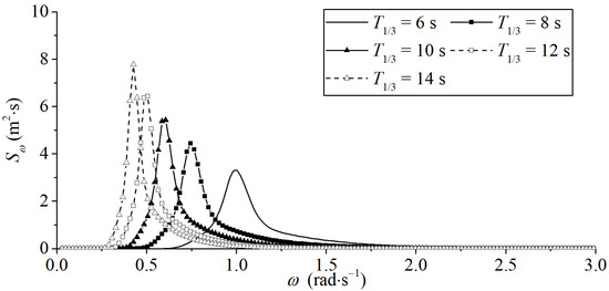
Figure 8.
Comparison of wave spectra under different significant wave periods.
In order to analyze the motion response pattern of the SFT, Figure 9 and Figure 10 show the displacement time history curves in surge and heave directions with different section forms when the significant wave period T1/3 = 6 s occurs. It can be seen from the displacement time history curves that the surge displacement is usually smaller than the heave displacement, because the SFT mooring system is anchored by four inclined tension legs, and the stiffness in the surge direction provided by the system is greater than the stiffness in the heave direction, making the surge movement smaller. Upon comparing the first- and second-order motion responses, it is observed that the second-order motion response has a relatively minor impact on the overall motion response, thereby indicating that second-order wave forces exert a minor influence on the structural design of SFTs.
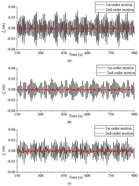
Figure 9.
First- and second-order time history curves of SFT in surge direction: (a) twin-circular section, (b) elliptical section, (c) round rectangular section (T1/3 = 6 s).
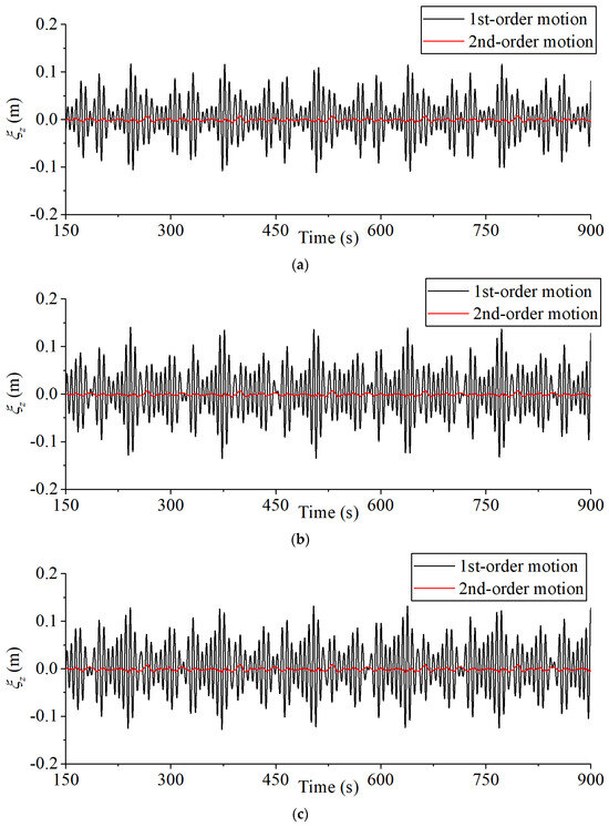
Figure 10.
First- and second-order time history curves of SFT in heave direction: (a) twin-circular section, (b) elliptical section, (c) round rectangular section (T1/3 = 6 s).
Then, the surge and heave displacement of each section is Fourier-transformed to obtain three-dimensional (3D) renderings under different significant wave periods, as shown in Figure 11 and Figure 12. The results show that the spectra in the surge direction present double-peak spectra under the action of irregular waves with short periods (T1/3 = 6 s, T1/3 = 8 s), and the frequencies correspond to wave frequency and natural frequency in the surge direction, which indicates that there are obvious motion characteristics at wave frequency and natural frequency under the action of short-period waves. The surge displacement spectrum presents a single peak spectrum phenomenon of wave action in an increase in wave period (T1/3 = 10 s, T1/3 = 12 s, T1/3 = 14 s), indicating that the SFT is mainly affected by wave frequency under the action of a long wave.
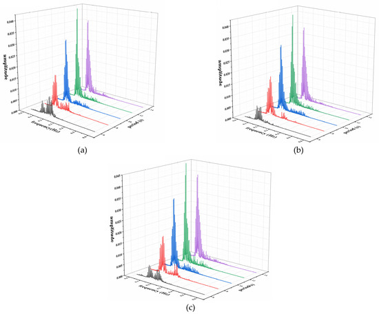
Figure 11.
The 3D Fourier transform results of surge displacement of each section under different significant wave periods: (a) twin-circular section; (b) elliptical section; (c) round rectangular section.
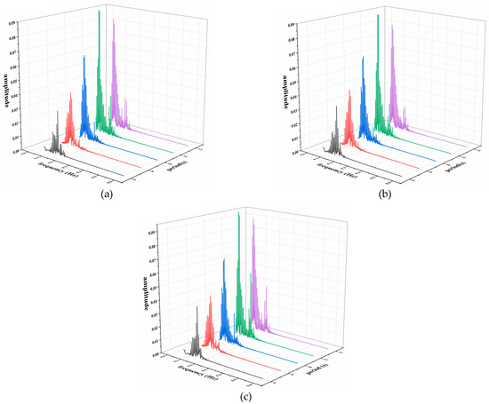
Figure 12.
The 3D Fourier transform results of heave displacement of each section under different significant wave periods: (a) twin-circular section; (b) elliptical section; (c) round rectangular section.
Figure 13 shows the displacement statistical analysis of the three types’ section forms. The histogram is the effective values of the motion response, and the curves are the extreme values of the motion response. The results indicate that the round rectangular section has the largest motion response in irregular waves, both in surge motion and heave motion.
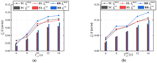
Figure 13.
Displacement statistical analysis of different section forms: (a) in surge direction; (b) in heave direction.
The displacement statistical results are further analyzed, and the comparisons of the maximum values and significant values are analyzed, as shown in Table 4. The results show that the positive displacement is often greater than the negative displacement (the ratio is greater than 1) in the surge direction; that is, under the action of the second-order wave force, the SFT moves along the wave propagation direction in the surge direction. However, because the second-order component is small, the amount of motion in the surge and heave directions is not obvious, and the ratio results of the max value are greater than those of the significant value, which means that the max value of SFT motion is more discrete than the significant value. In the heave direction, the positive displacement is often less than the negative displacement (the ratio is less than 1); that is, under the action of second-order Stokes waves, the second-order set-down term is more obvious, and the SFT shows a downward movement trend. In the pitch motion, the ratio is a little less than 1.0, which means that the SFT rotates slightly towards the back-wave direction.

Table 4.
Comparisons of motion offset of different section forms.
Then, the ratios of positive and negative maximum values to effective values are analyzed here, as shown in Figure 14 and Figure 15. On the whole, the dispersion degree of motion in each direction gradually decreases with an increase in the significant wave period. From the comparison of the dispersion degree of the three section forms, the motion of the elliptical shape section is the smallest in each direction, indicating that the elliptical shape SFT is relatively the most stable in all directions under irregular waves.
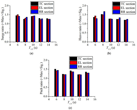
Figure 14.
Comparisons of positive motion dispersion in each direction under different wave periods of different section forms: (a) surge ratio; (b) heave ratio; (c) pitch ratio.
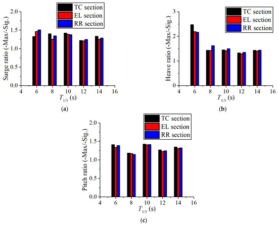
Figure 15.
Comparisons of negative motion dispersion in each direction under different wave periods of different section forms: (a) surge ratio; (b) heave ratio; (c) pitch ratio.
3.3. Mooring Analysis of SFT with Different Section Forms
Figure 16 shows the mooring tension time history curves of different section forms under irregular waves (significant wave period T1/3 = 6 s). It can be seen that the tension time history curves of each section are irregular, and the tension values of middle tension legs (No. 2 and No. 3) are greater than those of side tension legs (No. 1 and No. 4), and fluctuate up and down around their respective pretensions.
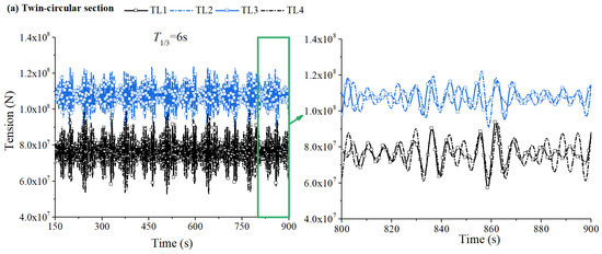
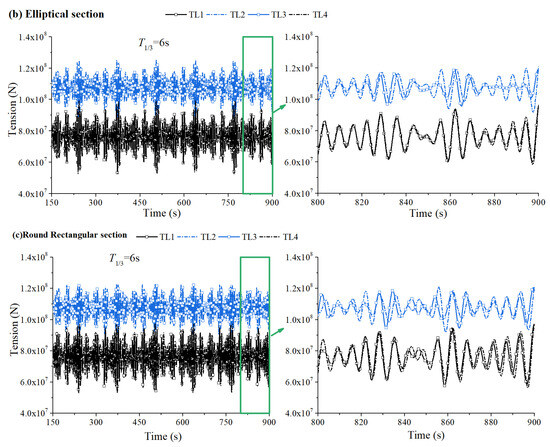
Figure 16.
Mooring tension time histories of different section forms: (a) twin-circular section; (b) elliptical section; (c) round rectangular section (T1/3 = 6 s).
Figure 17 shows the statistical analysis of the tension of SFT with different sections and different periods. It is found that the RMS and maximum value of mooring tension increase with an increase in wave period. The second-order nonlinear motion of the SFT leads to the force on the up-wave tension leg being greater than that on the back-wave tension leg. Comparing the four mooring chains TL1 to TL4, it is found that the tensions of TL2 and TL3 are greater than those of TL1 and TL4. The reason is that the inclination of middle tension legs (TL2 and TL3) is relatively large; when the same vertical pretension is provided with side tension legs (TL1 and TL4), it is also necessary to provide greater horizontal stiffness. It is suggested that the tension leg stiffness of the SFT tension leg mooring should be moderately increased in the direction of the normal wave according to the actual sea conditions. The greater the inclination angle of the tension leg, the greater the stiffness also needs to be. Comparing the ratio of the maximum value and the RMS of each tension leg of SFT with different sections, as shown in Figure 18, it is found that the ratio increases with an increase in the wave period, and the ratio measured in the up-wave is greater than that measured in the back-wave through the comparisons, which proves that the up-wave tension leg bears greater tension changes. By comparing the three types of section forms, it is found that the tension ratio of the elliptical shape section is the smallest, which further proves that the elliptical shape section is more stable in irregular waves.
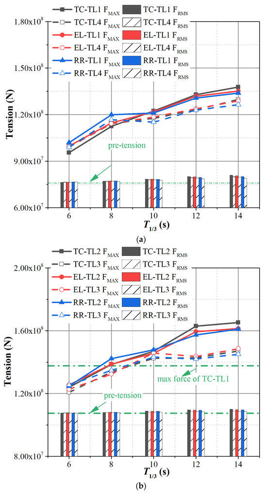
Figure 17.
Mooring tension statistical analysis of different section forms: (a) TL1 and TL4; (b) TL2 and TL3.
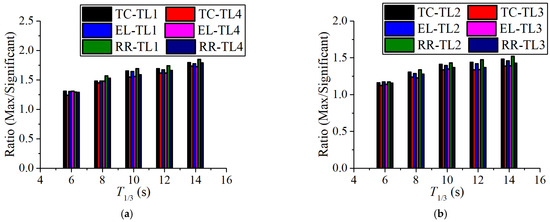
Figure 18.
Mooring tension ratio of different section forms: (a) TL1 and TL4; (b) TL2 and TL3.
4. Conclusions
In this paper, the second-order time-domain 2D numerical model of waves and structures based on the potential flow theory is used to calculate the dynamic characteristics of the dual-lane SFT with different section forms. The motion response and mooring line tension of the SFT with different section forms in irregular waves with different wave periods are analyzed, and the following conclusions are obtained:
(1) The displacement presents double-frequency motion characteristics under the action of irregular waves with short periods, and the corresponding frequencies correspond to wave frequency and natural frequency. When the long-period wave acts on the structure, the motion of SFT is mainly affected by wave motion.
(2) The SFT section moves along the wave propagation direction in the surge direction. In the heave direction, the second-order set-down term is obvious, and the SFT shows a downward movement trend. In the pitch motion, the SFT rotates slightly towards the back-wave direction. The dispersion degree of motion in each direction gradually decreases with an increase in the significant wave period. The motion of the elliptical section is the smallest in each direction, indicating that the elliptical section SFT is the most stable in all directions under irregular waves.
(3) The RMS and maximum value of mooring tension increase with an increase in the wave period. The tensions of middle tension legs are greater than those of side tension legs. The greater the inclination angle of the tension leg, the greater the stiffness also needs to be. And the up-wave mooring line bears greater tension changes. The ratio of max and RMS tension of the elliptical shape section is the smallest, which further proves that the elliptical section is the most stable.
Author Contributions
Methodology, R.J.; Formal analysis, M.H.; Data curation, Y.Z.; Writing—original draft, R.J.; Writing—review & editing, Z.Z. All authors have read and agreed to the published version of the manuscript.
Funding
This work was supported by the Key Research and Development Program (2022YFB2602800), National Natural Science Foundation of China (U2106223, U21A20123), and the Basic Funding of the Central Public Research Institutes (TKS20230106).
Data Availability Statement
Data is contained within the article.
Conflicts of Interest
The authors declare no conflict of interest.
Appendix A
Appendix A.1. Dynamic Force of Mooring Line
In the deformed configuration, the centerline of the rod is represented by the spatial curve r(s, t), as depicted in Figure A1. The position vector r is a function of both the arc length s and time t.
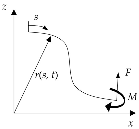
Figure A1.
Coordinate system of rod.
Assuming that there is no torque and applied external moment on a mooring line, a linear momentum conservation equation with respect to a position vector r(s,t) can be derived.
where FMI is internal force, q is the external force per unit length, ρ is the mass per unit length, and r’ is the unit cut vector. The point ‘∙’ above the vector r indicates the derivative of the time, EI is the bending stiffness, T is the local tension, and κ is the local curvature. The scalar variable λ can be regarded as a Lagrange multiplier. If the rod is considered stretchable, and stretching is linear and small, the following extensible condition must be satisfied:
For these equations, geometric nonlinearity is fully considered and there is no special assumption made concerning the shape or orientation of lines. Equation (A3) is directly defined in a global coordinate system and does not require any transformations to the local coordinate system.
For most ocean structures, the external forces acting on the mooring lines mainly come from the hydrostatic pressure and hydrodynamic load of the fluid around the lines as well as the weight of the mooring line, so q can be expressed as
where w is the gravity of the mooring line per unit length in the air; Fs and Fd are hydrostatic and hydrodynamic load per unit length, respectively. The hydrostatic force can be written as
where B is buoyancy per unit length; the scalar P is the hydrostatic pressure force at any point r on the mooring line. Hydrodynamic load is obtained from the Morison equation.
where CA is added mass per unit length, CM is the inertia force on the unit normal vector per unit length, and CD is the drag force on the unit normal vector per unit length. Vn and are the normal fluid velocity and acceleration perpendicular to the centerline of the mooring line, respectively. and are the normal member velocity and acceleration components. By combining Equations (A1), (A4), (A5), and (A6), the motion equation of the mooring line considering weight and hydrostatic and hydrodynamic load can be obtained as
where
where is effective tension, and is effective gravity or wet gravity.
Equations (A2) and (A7) are the basic governing equations for the mooring cable finite element analysis.
Appendix A.2. Coupled Dynamic Analysis
The first- and second-order motion equations for a hull system are expressed as follows:
where [M] is the mass matrix, [B] is the viscous damping matrix, [C] is the restoring matrix, and is the kth-order mooring force. A coupling analysis of the hull system can be achieved by applying appropriate boundary conditions at the fairleads. In this study, hinged boundary conditions are used at the junction of the mooring line and the floater. The coordinates of the mooring point of the lth cable in the body-fixed coordinate system are rcl and the coordinates of the rotation center in the body-fixed coordinate system are r0. At any time, the coordinates of the mooring point in the space-fixed coordinate system are Rcl, which can be expressed as
where MT is a transformation matrix between a body-fixed coordinate system and a space-fixed coordinate system, and is an orthogonal matrix, MTt = MT−1. The expression of MT is
It is assumed that the mooring point is at the top unit and the forces on the mooring cable tension leg at the mooring point are
If the mooring system of the floating body contains L mooring cables, based on the relationship between the force and reaction force, the force on the floating body is
In order to describe the problem concisely and conveniently, coupled motion Equations (A11) and (A12) of the floating body are written in the following general form:
where FM(t) is mooring force at the t moment, and F(t) is the sum of other forces. The mooring line dynamic equation is as follows:
and the coefficients of the mass matrix, the stiffness matrix, and the force vector in Equation (A18) are similar to the expression in Tahar and Kim’s work [27]. The detailed coupled analysis process is similar to the expression in Yang et al.’s work [28].
At the time step K + 1, the predictors , , and , for motions of the hull, are given by
For the free-surface boundary conditions, the fourth-order Adams–Bashforth–Moulton method is used for time integration. The kinetic and dynamic free-surface boundary conditions can be written in a general form of function as follows:
The fourth-order Adams–Bashforth method is used to predict the wave elevation and velocity potential on the free surface as follows:
At the time step K + 1, the coefficients at both sides of the incremental motion for the hull are computed using , , , , and . The incremental motion for the hull is expressed as
The correctors of , , and are given by
The fourth-order Adams–Moulton method is used to correct the wave elevation and the velocity on the free surface as follows:
Go back to the incremental motion and iteration until is small enough, then continue for a new time step. The specific process is shown Figure A2.
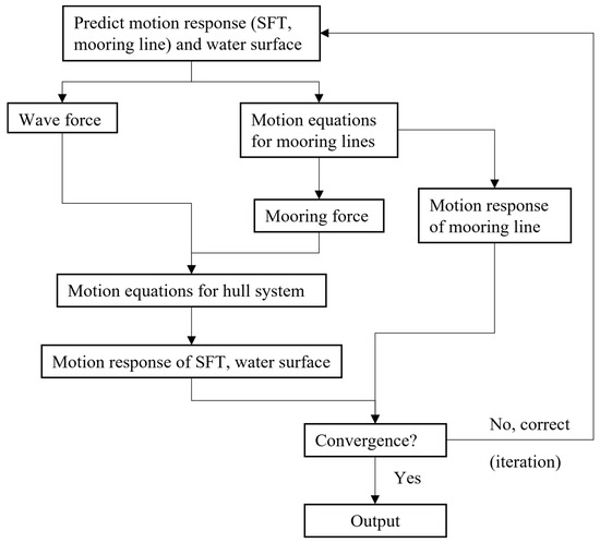
Figure A2.
Calculation process of wave–structure–mooring numerical model.
References
- Xiang, Y.Q.; Chen, Z.Y.; Yang, Y. Research Development of Method and Simulation for Analyzing Dynamic Response of Submerged Floating Tunnel. China J. Highw. Transp. 2017, 30, 69–76. (In Chinese) [Google Scholar]
- Geng, B.L.; Liu, Y.; Hu, C.Q.; Jin, R.J. Overview of hydrodynamic study for submerged floating tunnel. J. Waterw. Harb. 2020, 41, 1–8. (In Chinese) [Google Scholar]
- Zhang, H.Q.; Yang, Z.W.; Li, J.Z.; Yuan, C.; Xie, M.; Yang, H.; Yin, H. A global review for the hydrodynamic response investigation method of submerged floating tunnels. Ocean. Eng. 2021, 225, 108825. [Google Scholar] [CrossRef]
- Xiang, Y.Q.; Lin, H.; Bai, H.; Chen, Z.Y.; Yang, Y. Numerical simulation and experimental study of submerged floating tunnel subjected to moving vehicle load. Ocean. Eng. 2021, 235, 109431. [Google Scholar] [CrossRef]
- Jin, C.; Chung, W.C.; Kwon, D.S.; Kim, M.H. Optimization of tuned mass damper for seismic control of submerged floating tunnel. Eng. Struct. 2021, 241, 112460. [Google Scholar] [CrossRef]
- Wu, Z.W.; Wang, D.X.; Ke, W.; Qin, Y.H.; Lu, F.C.; Jiang, M.J. Experimental investigation for the dynamic behavior of submerged floating tunnel subjected to the combined action of earthquake, wave and current. Ocean. Eng. 2021, 239, 109911. [Google Scholar] [CrossRef]
- Won, D.H.; Park, W.S.; Kim, S. Cyclic bending performance of joint on precast composite hollow RC for submerged floating tunnels. Mar. Struct. 2021, 79, 103045. [Google Scholar] [CrossRef]
- Won, D.H.; Seo, J.H.; Pak, W.S.; Kim, S.K. Torsional behavior of precast segment module joints for a submerged floating tunnel. Ocean. Eng. 2021, 220, 108490. [Google Scholar] [CrossRef]
- Won, D.H.; Park, W.S.; Kim, S.J. Vibration characteristics of submerged floating tunnels with suspension cables according to wave periods. Ocean. Eng. 2022, 254, 111342. [Google Scholar] [CrossRef]
- Wu, L.J.; Ma, Y.F.; Liu, M.W.; Wang, Z.H.; Liu, B. Nonlinear characteristics of semirigid and semiflexible segment joints of submerged floating tunnels under the combined axial force and bending moment. Ocean. Eng. 2021, 265, 112651. [Google Scholar] [CrossRef]
- Kwon, D.S.; Jin, C.; Kim, M.H. Prediction of dynamic and structural responses of submerged floating tunnel using artificial neural network and minimum sensors. Ocean. Eng. 2022, 244, 110402. [Google Scholar] [CrossRef]
- Min, S.; Jeong, K.; Noh, Y.; Won, D.; Kim, S. Damage detection for tethers of submerged floating tunnels based on convolutional neural networks. Ocean. Eng. 2022, 250, 111048. [Google Scholar] [CrossRef]
- Shao, D.; Zheng, J.H.; Zhang, J.S.; Yang, Y.F.; Zhang, J.X. Vibrating behavior of submerged floating tunnel in current field investigated with hybrid vector-autoregressive model. Ocean. Eng. 2022, 256, 111359. [Google Scholar] [CrossRef]
- Liu, T.; Viuff, T.; Leira, B.J.; Xiang, X.; Minoretti, A.; Halse, K.H. Response validation of a submerged floating tunnel segment. Ocean. Eng. 2022, 264, 112396. [Google Scholar] [CrossRef]
- Xiang, Y.Q.; Yang, Y. Spatial dynamic response of submerged floating tunnel under impact load. Mar. Struct. 2017, 53, 20–31. [Google Scholar] [CrossRef]
- Sharma, M.; Kaligatla, R.B.; Sahoo, T. Wave interaction with a submerged floating tunnel in the presence of a bottom mounted submerged porous breakwater. Appl. Ocean. Res. 2020, 96, 102069. [Google Scholar] [CrossRef]
- Faggiano, B.; Panduro, J.; Mendoza Rosas, M.T.; Mazzolani, F.M. The conceptual design of a roadway SFT in Baja California, Mexico. In Proceedings of the 2nd International Symposium on Submerged Floating Tunnels and Underwater Tunnel Structures, Chongqing, China, 16–18 December 2016; Volume 166, pp. 3–12. [Google Scholar]
- Jin, R.J.; Liu, Y.; Geng, B.L.; Zhang, H.Q. Hydrodynamic characteristics of circular tube structure with wave action. J. Waterw. Harb. 2019, 40, 249–258. (In Chinese) [Google Scholar]
- Liu, Y.; Jin, R.J.; Geng, B.L.; Ren, C.P. Influence of anchor cable inclination angle on motion response of submerged floating tunnel with different section. J. Hydrodyn. 2020, 35, 237–247. (In Chinese) [Google Scholar]
- Chen, X.B.; Chen, Q.; Chen, Z.W.; Cai, S.Q.; Zhuo, X.R.; Lv, J.G. Numerical modeling of the interaction between submerged floating tunnel and surface waves. Ocean. Eng. 2021, 220, 108494. [Google Scholar] [CrossRef]
- Won, D.; Seo, J.; Kim, S. Dynamic response of submerged floating tunnels with dual sections under irregular waves. Ocean. Eng. 2021, 241, 110025. [Google Scholar] [CrossRef]
- Deng, S.; Ren, H.J.; Xu, Y.W.; Fu, S.X.; Moan, T.; Gao, Z. Experimental study on the drag forces on a twin-tube submerged floating tunnel segment model in current. Appl. Ocean. Res. 2020, 104, 102326. [Google Scholar] [CrossRef]
- Deng, S.; Ren, H.J.; Xu, Y.W.; Fu, S.X.; Moan, T.; Gao, Z. Experimental study of vortex-induced vibration of a twin-tube submerged floating tunnel segment model. J. Fluids Struct. 2020, 94, 102908. [Google Scholar] [CrossRef]
- Deng, S.; Xu, Y.W.; Ren, H.J.; Fu, S.X.; Li, S.; Moan, T.; Gao, Z. Numerical simulation of wave-induced hydroelastic response and flow-induced vibration of a twin-tube submerged floating tunnel. Mar. Struct. 2022, 82, 103124. [Google Scholar] [CrossRef]
- Shivakumar, B.P.; Karmaker, D. Hydrodynamic analysis of floating tunnel with submerged rubble mound breakwater. Ocean. Eng. 2022, 264, 112460. [Google Scholar]
- Jin, R.J.; Gou, Y.; Geng, B.L.; Zhang, H.Q.; Liu, Y. Coupled dynamic analysis for wave action on a tension leg-type submerged floating tunnel in time domain. Ocean. Eng. 2020, 212, 107600. [Google Scholar] [CrossRef]
- Tahar, A.; Kim, M.H. Coupled-dynamic analysis of floating structures with polyester mooring lines. Ocean. Eng. 2008, 35, 1676–1685. [Google Scholar] [CrossRef]
- Yang, M.D.; Teng, B.; Ning, D.Z.; Shi, Z.M. Coupled dynamic analysis for wave interaction with a truss spar and its mooring line/riser system in time domain. Ocean. Eng. 2012, 39, 72–87. [Google Scholar] [CrossRef]
Disclaimer/Publisher’s Note: The statements, opinions and data contained in all publications are solely those of the individual author(s) and contributor(s) and not of MDPI and/or the editor(s). MDPI and/or the editor(s) disclaim responsibility for any injury to people or property resulting from any ideas, methods, instructions or products referred to in the content. |
© 2024 by the authors. Licensee MDPI, Basel, Switzerland. This article is an open access article distributed under the terms and conditions of the Creative Commons Attribution (CC BY) license (https://creativecommons.org/licenses/by/4.0/).