1. Introduction
A manhole is the most crucial appurtenant structure, usually located at the connection of a pipe to a sewer network, where it is necessary to change the direction or slope of the pipeline [
1]. The flow inside manholes is typically three-dimensional, highly turbulent, and possibly multiphase. After entering the manhole, the flow encounters sudden expansion and contraction, resulting in local energy loss. This energy loss makes it an essential element for the hydraulic modeling of sewer networks. Urban drainage systems are generally designed to operate in free-surface flow conditions. Under normal operating conditions, the water level at any point in pipes remains below the top of the conduit, creating gravity-driven free-surface flow. However, when the maximum carrying capacity of the network is exceeded, the water level in the pipeline rises, pressurized flow occurs in the network, and manholes are surcharged. Surcharged flow in manholes raises their loss coefficient and creates an additional pressure drop on the drainage network, which becomes essential for an extended network with many manholes [
2].
In the past, manhole losses were not considered in modeling sewer systems. Nowadays, energy losses in manholes are included in calculations with different approaches in most network hydraulic modeling programs [
2,
3,
4]. Sewer system hydraulic modeling based on one-dimensional St. Venant Equations and three-dimensional complex flow behavior cannot be represented [
1,
5,
6,
7]. Instead, experimentally obtained manhole loss coefficients are included in the model as local constraints [
2,
3,
8]. Moreover, recent modeling studies based on surface flows and the interactions of piped drainage networks are crucial for precise flood risk assessment and urban planning [
6,
9,
10,
11].
Complex flow conditions are observed in manholes, where angled or perpendicular inlet and outlet flows pass through [
9]. The inlet and outlet flow in different directions make the surface wavy and undulating, and vortex formations are observed in some regions of the manhole. Moreover, transitions between wholly and partially filled pipes are generally seen in the manhole regions [
10,
12,
13]. Moreover, the complex nature of flow is affected by an almost infinite variety of geometrical and hydraulic factors [
14]. Some critical factors are the inflow rate, the shape of a manhole, surcharge condition, connecting pipe size, angle of connection, and manhole diameter ratios, among others [
15,
16,
17,
18,
19,
20].
Different manhole molds have been developed with research and used in applications due to the regulations of other countries. They can be distinguished by the presence of a bench or a sump zone, which can affect the energy loss coefficient and energy loss of the drainage network [
18,
21]. Studies reveal that the mold of the manhole bottom can influence the shape and expansion of the water jet [
22,
23]. Therefore, the form of the mold affects the energy loss of the manhole. Different manhole molds are tested on distinct scaled models and flow conditions [
18,
24,
25]. As a result, there is no adequate comparison in the literature regarding the effects of the energy loss coefficient of the manhole mold due to surcharged and variable flow conditions.
The use of manholes is emphasized by the regulations when the pipe flow direction is to be changed in the networks. Unlike the straight flow, the flow jet is not directed toward the outlet pipe but changes direction by hitting the boundaries of the manhole structure. Changing different manhole entrance directions can also change the head loss coefficient. Previous investigations into this issue include the study of acute bending angles between inlet and outlet piping commonly found in sewer network design, such as 135° and 90° bends [
25,
26,
27]. There are limited studies on directional changes outside these angles [
3]. Bend angles between 165° and 180°are rarely designed in a network; however, they may be construction and design deviations [
27].
One of the most relevant parameters for the energy loss of a manhole is the ratio of manhole diameter to pipe diameter. Research shows that with an increase in the manhole-to-pipe diameter ratios, the head loss coefficients increase, therefore decreasing the hydraulic performance of the manhole [
24,
28,
29]. Local government standards give the minimum diameter of the manhole size; however, the pipe diameter is hydraulically restricted. As a result, the ratio of the manhole diameter to the pipe diameter is not a freely chosen parameter. The ratio may reach up to six for sanitary sewer network projects. In most manhole experimental studies in the literature, the ratio is under four.
Today, with advances in computational fluid dynamics (CFD) and computational power, CFD technology is increasingly being used in hydraulic research as an alternative and/or complementary method for laboratory experiments. Compared with the physical model studies, the CFD model in the sewer connection study has several advantages. First, the CFD model is generally cost-effective and efficient and does not need to be concerned with scale effects. Evaluating the accuracy of the used CFD programs and modeling methods is the primary focus of many studies [
26,
30,
31,
32,
33,
34,
35]. A proven CFD model can be used as a design tool to optimize the design of sewer connections [
36,
37]. The capabilities of the CFD model can be advantageous in providing details of flow structures, such as velocity distribution, turbulence, separation, and flow mixing at sewer connections [
27].
In this study, the energy loss coefficients of the manholes were determined when the ratio of the diameter of the manhole to the diameter of the pipe was greater than four. Studies were carried out in flat, half-bench, and full-bench manholes, which are the most common mold types. Connections were made with 180°, 90°, and 135° angles to observe the effect of the current direction change. All manhole geometries produced for experimental studies were analyzed with the Ansys FLUENT program, and the results were compared.
2. Materials and Methods
2.1. Hydraulics of a Surcharged Manhole
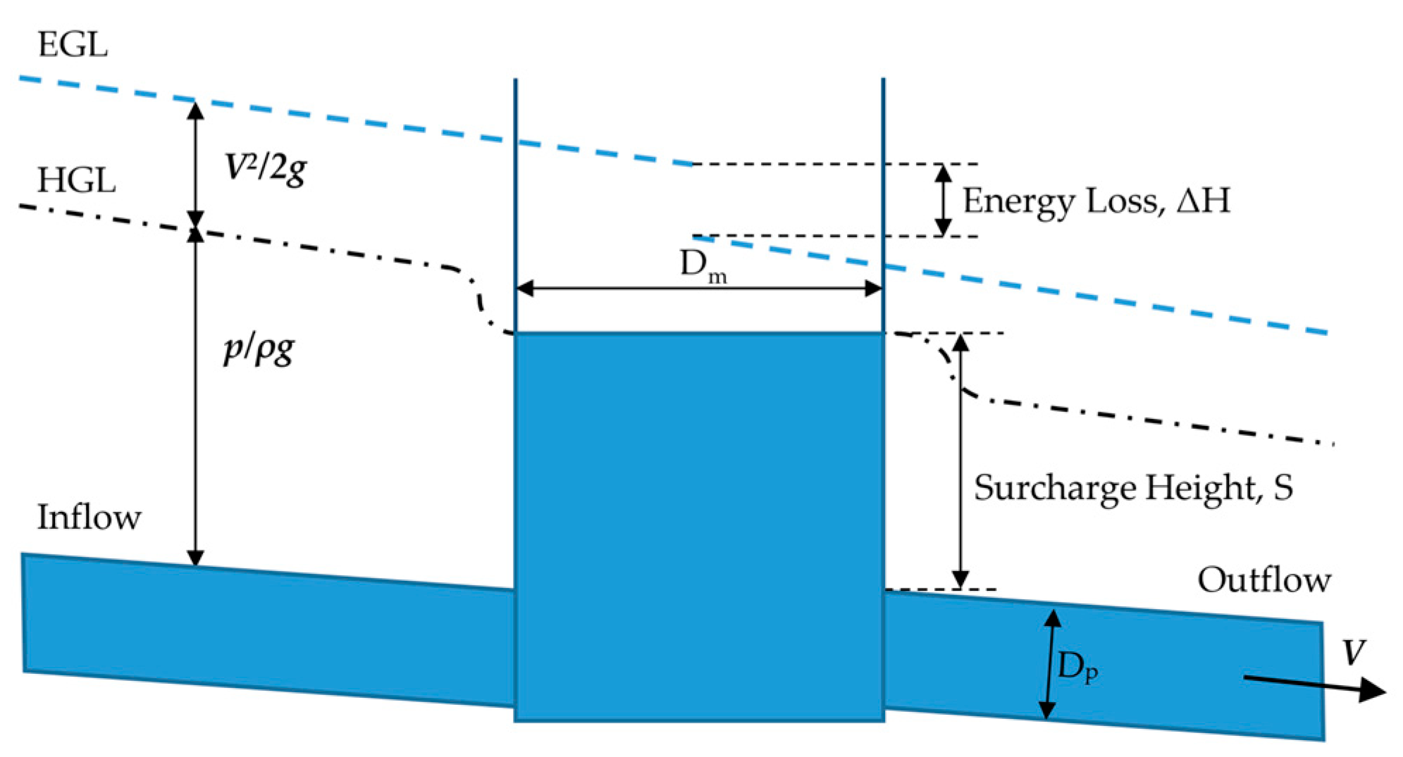
The pressurized flow occurs at inflow and outflow pipes in the surcharged flow condition. A sudden change in the flow cross section of the surcharged manhole causes a remarkable increase in energy loss compared with that observed in open-channel flow [
38]. As the flow enters the manhole, it expands near the manhole entrance, contracts near the exit, and creates complex three-dimensional flow fields (
Figure 1). The surcharged manhole energy loss coefficient varies depending on the manhole surcharge height. Previous studies have shown that at very low overloads, pressure drops rapidly without any trend [
25,
27,
28].
According to the submerged jet theory, when the flow from the inlet pipe enters the surcharged manhole, it behaves like a jet and is divided into two zones [
22]. As the jet travels through the outlet faster, the inner core zone becomes narrow, and the outer diffusion zone becomes larger. The expended diffusion zone height may reach up to 0.2 manhole diameter D
m. This height is called the threshold surcharge [
39,
40]. If the available surcharge height in the manhole is lower than the threshold height, the velocity of the diffusion zone interacts with the free surface of the manhole and produces an additional energy loss. Surcharges below or above the threshold value are referred to as “pre-threshold surcharges” and “post-threshold surcharges” [
39,
41]. At the post-threshold surcharge, the manhole energy loss factor is assumed to be independent of its surcharge height.
The abrupt expansion and compression that occur when a pipe flow goes through a manhole at the entrance and exit are the primary causes of energy loss. The Equation (1) is used to compute the head loss coefficient, K:
where
is the averaged flow velocity in the outlet pipe, ΔH is the change in energy head at the manhole center, and g is the gravitational acceleration. The variation in energy head in a manhole is seen in
Figure 1. The energy grade lines are computed at the inlet and output pipes. The difference between the extrapolated energy grade lines at the center of the manhole is the head loss due to the manhole. Surcharge height S is the distance between the water level in the manhole and the soffit level of the outlet pipe. The surcharge ratio (S/D
p) was calculated from each experiment measurement of surcharge height as the ratio between surcharge heights and outlet pipe diameter.
2.2. Experimental Setup
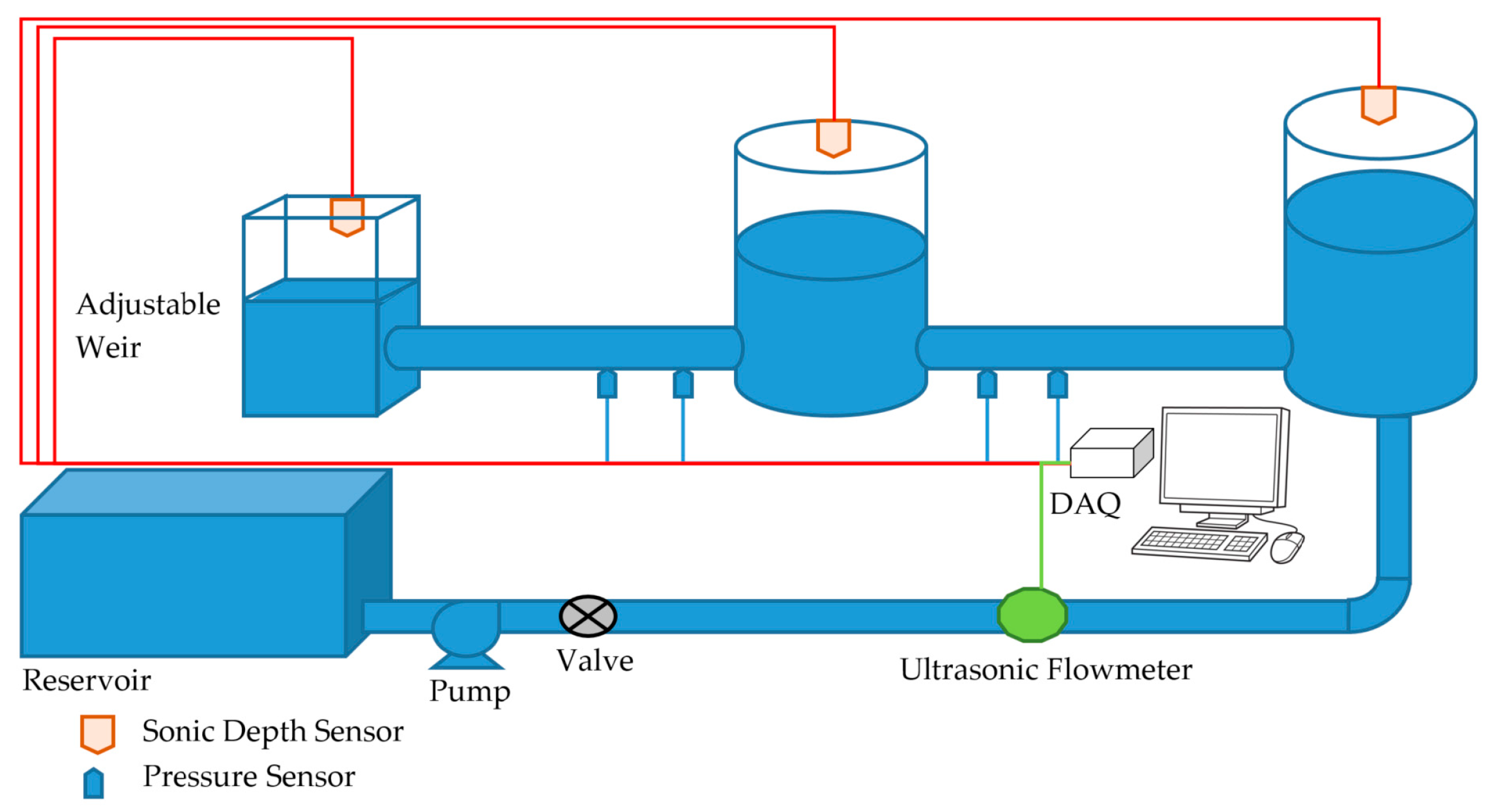
The physical model scale of 1/4 of the prototype (
Figure 2) was operated at the Zonguldak Bulent Ecevit University Engineering Faculty Hydromechanics Laboratory. The manhole diameter was D
m = 244 mm, and the pipe diameter was D
p = 46 mm. The inlet and outlet pipes had the same internal diameter and were connected at the same invert level. All the pipes and tanks were made from transparent acrylic materials. The sewer pipes were arranged horizontally in the experiments. The distance between the center of the upstream and downstream tanks to the manhole center was 2.25 m. Piezometer openings were formed by drilling 2.5 mm diameter holes in test pipes that were 0.4 m away from the manhole wall and each other. Water was pumped to the upstream tank, and then the inflow to the model was valve-controlled to facilitate the discharge. A computer-connected Data Acquisition System (DAQ) (National Instrument NI_DAQ 6210, Austin, TX, USA) was used to measure pressure (GENTEK, GPT124B, İstanbul/Turkey) variation in pipes and water levels (Microsonic, mic+25, Dortmund/Germany) in the manhole, upstream, and downstream tanks. An ultrasonic flow meter (BCTS, JC-3000H, Jiangsu/China) mounted on the inlet pipe was used to measure the discharge. The submergence could be varied by an adjustable weir in the downstream tank.
One of the three molds was installed in the manhole to prepare it for experimental runs. The pressure transmitters were calibrated before each set of experiments. The facility’s flow was set to ensure that both the Reynolds number and the level of surcharge were high enough. Pressures and water levels were recorded with the computer-controlled Data Acquisition System (DAQ) after stabilizing the installation’s flow. To avoid possible errors in pressure and water level measurements caused by fluctuations during the experiment, at least 3 min with 50-hertz-sample-rate data were recorded and analyzed later. Discharge was measured. The collected experiment data set was then analyzed by a computer program that calculated the total energy at individual points and water levels at the manhole and outlet tank. The energy grade lines upstream and downstream of the junction were assessed using pressure readings from measurement points. The manhole energy loss was calculated as the difference between the energy grade lines upstream and downstream at the junction axis. The identical process was then carried out once again for each discharge. The head loss coefficient was then determined by plotting the observed head losses against the velocity heads.
2.3. Manholes Considered for Analysis
The misuse of sanitary sewer systems is not only a problem for underdeveloped countries but is also very common in developed countries [
42,
43,
44,
45]. The main causes of sewer overflows are pipeline problems (blockages, line breaks), sewer defects (stormwater and groundwater overload), and improper design.
The Canadian sewer system was examined based on the pipes’ diameter group and the length of pipes, with a diameter of up to 250 mm, which is almost 70% of the total pipe length of the network, where the minimum size of manhole diameter is 1000 mm [
46]. As a result, the ratio of manhole diameter to pipe diameter larger and equal to four is the most common in sewer systems. The maximum manhole diameter to pipe diameter ratio, D
m/D
p, is around 3 for storm sewer systems; however, sanitary networks’ maximum ratio is around 5. In most head loss coefficient studies, the ratio is chosen to be between 2 and 4 [
24,
25,
47], and there are a few studies with ratios equal to or larger than 5. In this study, to clarify the head loss coefficient of manholes, especially for sewer systems, the ratio of manhole diameter to pipe diameter was chosen to be 5.3. Three different manhole molds were chosen to analyze the hydraulic effects on the loss coefficient (
Figure 3). The Type A manhole has a flat bottom with a sump zone 1/3 D
p from the inlet pipe invert level. The Type B manhole has a half-circular invert with a right-angled intersection point called a half bench. Type A and B manholes are commonly used in Türkiye’s sewer system. The Type C manhole has a U-type invert to give it a more hydraulically shaped bottom called a full bench.
In urban sewer systems, the majority of manholes are two-way constructions with straight or angled flow [
48]. The most common connection alignments are 180°, 90°, and 135°. Type A manholes were examined for all three alignments. Type B and Type C manholes were examined for 180° and 90° connections.
2.4. Numerical Model Procedures and Boundary Conditions
This study’s manhole hydraulic models included completely surcharged manholes that connected full-pipe flows. During this study, the manhole loss coefficients were calculated numerically for conditions where outlet pipe pressures and manhole water levels were obtained experimentally.
In the literature, many studies use the CFD modeling approach to investigate flow behavior in surcharged manholes. The method for validating a CFD manhole model was described by Stovin et al. [
31]. Treatment of the free surface is a significant problem in the CFD modeling of sewer structures. Two alternative approaches—the rigid lid approximation and the Volume of Fluid (VOF) method—are frequently used for modeling the free surface. The free surface is thought of as a frictionless plane at a given point in the rigid lid approximation. Published studies reveal that the rigid lid approach reproduces the mean flow field more accurately [
32,
49,
50]. Scaled surcharged manhole behavior was simulated, and solute transport through it was predicted utilizing rigid lid approximation using the CFD modeling software Ansys 14.5 FLUENT [
50,
51,
52]. Moreover, many researchers have performed free-surface flow simulations using the rigid lid approach with complicated turbulence closure models [
32,
53,
54]. The determination of free-surface location is a part of the solution in the Volume of Fluid (VOF) method [
44]. When the location of the free surface is unknown, this is regarded as the preferred course of action [
33,
39,
55,
56,
57].
For manhole mixing investigations, CFD simulation with the k-ε realizable turbulence model and rigid lid approach reproduces the mean flow field more accurately at different hydraulic regimes [
58]. Mignot et al. [
32] performed a flow simulation at an open-channel junction. The free surface is defined as a rigid lid with a free-slip condition. Saiyudthong [
49] published results from the simulation of CFD in terms of the energy loss coefficient and visual mechanisms taking place in a circular surcharged manhole with changes in pipe direction. The free surface was specified as the frictionless rigid lid. Saiyudthong [
49] concluded that the surface simulation technique has a minor influence on energy loss coefficients when the manhole is highly surcharged. Zhao et al. [
26] and Motlagh et al. [
13] performed numerical simulations for rectangular and circular manholes, in which they used the VOF method to define the surface shape and location. Besides the surface properties, they also calculated the energy loss coefficients from the CFD results, compared them with the experimental results, and approved them. Molds and inlet alignment effects on the hydraulics of circular and square manholes and surcharge on gully manholes are some other good examples of studies with the VOF method [
27,
56].
The CFD model is based on the solution provided by the Reynolds-Averaged Navier–Stokes Equation. In Reynolds averaging, the solution variables in the instantaneous Navier–Stokes equations are decomposed into the mean and fluctuating components. For the velocity components:
where
and
are the mean and fluctuating components of velocity, respectively. Similarly, other scalar quantities are decomposed as flow
; where
denotes a scalar such as pressure, energy, or species concentration. Cartesian tensor forms the continuity Equation (2), and the momentum Equation (3) can be written as follows:
where
is the density of the fluid,
is the axis component of the velocity,
is viscosity, and
the Kronecker delta function. The last term in the equation is the turbulence shear stress, and it must be modeled for high-Reynolds-number flows. The basic approach for the modeling of turbulence shear stress based on the Boussinesq hypothesis is given in Equation (4). The shear stresses are defined with the gradient of the average velocity field with the hypothesis.
is turbulent viscosity, and
is kinetic energy production.
model families were taken into consideration for modeling the turbulence phenomena using the RANS technique. Three different models are available: standard, Reynold renormalization group (RNG), and realizable. The realizable
model has the immediate benefit of better predicting the spreading rate of both planar and round jets, flows involving rotation, separation, and recirculation [
34,
51]. Resolving the intricate flow inside the manhole was thought to be crucial for the simulations of manhole head losses. Therefore, for these simulations, the realizable k-ε turbulent model was employed [
59].
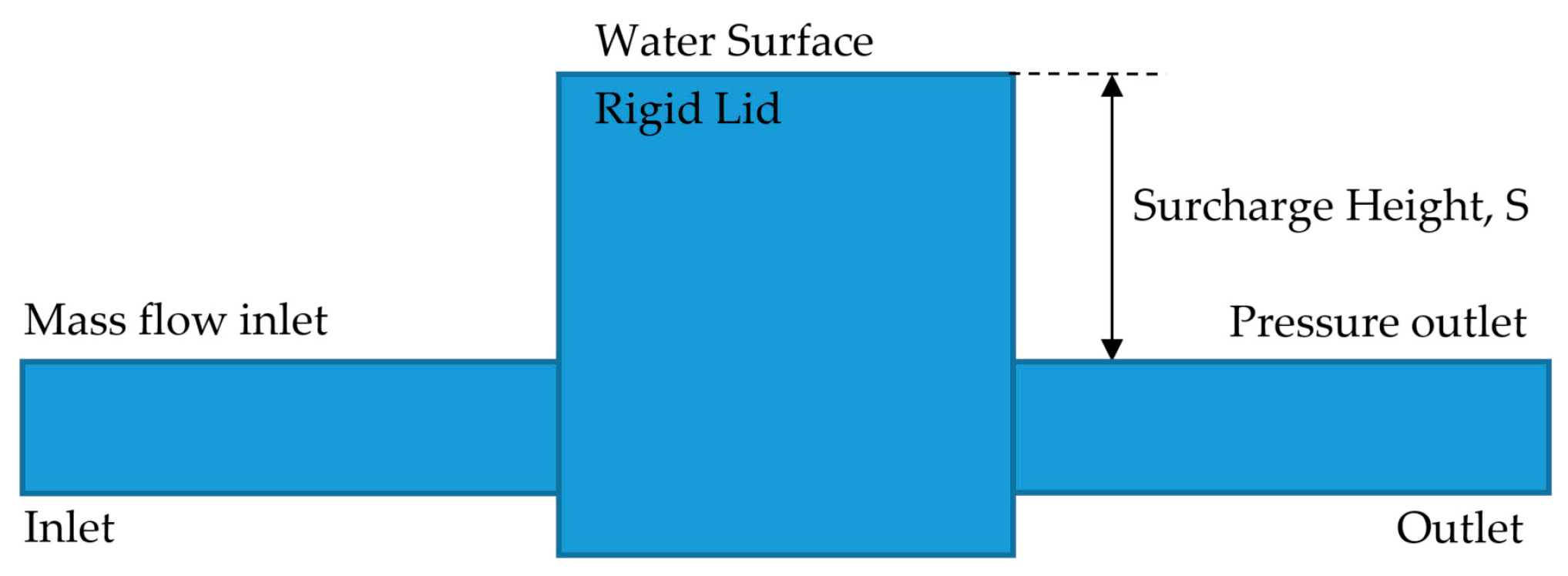
The three boundaries of the model are the water surface, inlet, and outlet (
Figure 4). The inlet boundary conditions were prescribed as a fully developed steady flow considering the mass flow rate of the section. A fixed gauge pressure boundary was prescribed at the outlet boundary condition. The water surface was modeled as a rigid lid with free slip, ensuring zero-shear stress at the surface. All the close wall boundaries were prescribed as no-slip conditions. All walls are specified as wall functions to save calculation time and do away with the need for thin-layered boundary meshes. Considering medium turbulence at the manhole, values of
,
, and
were computed for the turbulent wall function. The experimental facility, which was built with acrylic, was modeled numerically. In the wall boundary conditions, the roughness was not taken into account, since it was thought to be unimportant on the acrylic surface.
2.5. Computational Domain and Mesh
Three distinct computational meshes with various grid sizes were generated to test the mesh grid convergence using the realizable
turbulence model. The three meshes had corresponding minimum element size values of 2 mm for Mesh 1, 3 mm for Mesh 2, and 5 mm for Mesh 3. These meshes each included 3.109 million, 1.172 million, and 445 thousand cells, respectively. Following Celik et al. [
60], Richardson extrapolation was taken into account in the mesh convergence investigation. Flow parameters of the three meshes were determined to calculate the mesh convergence research. Meshed Type A manholes with different connection angles are given in
Figure 5.
Different parameters of the three meshes were determined to calculate the mesh convergence research. The iteration of the Equation (5) allowed for the calculation of the apparent order
for inlet pressure:
The values
and
in Equations (5) and (6), respectively, stand for the average mesh size ratio between Mesh 2 and Mesh 1, as well as the difference in data at a particular place between Mesh 2 and Mesh 1. Similar data from Mesh 3 and Mesh 2 are shown by values of
and
. S values that are negative signify oscillatory convergence. With the value of
, the Grid Convergence Index (GCI) Equation (8) may be determined.
where
is the computed approximate relative error between Mesh 2 and Mesh 1. Approximate relative error can be calculated from Equation (9).
The average mesh size ratio between Mesh 2 and Mesh 1, , and Mesh 3 and Mesh 2, , is 1.5 and 1.666, respectively. The difference in pressure at the entrance of Mesh 2 and Mesh 1, and Mesh 3 and Mesh 2, , is 9 and 26, respectively. Since the ratio of to is 0.346, the solution is monotonic convergent. The apparent order of accuracy, , was calculated with an iteration of 4.224. The approximate relative error is 0.004, and the Grid Convergence Index for fine mesh is calculated as 0.123%. Considering the duration of the simulation, Mesh 1 requires a substantial amount of processing resources due to the huge number of cells. Both the accuracy level and computing expenses are taken into account while choosing the cell size for this work, which is Mesh 2.
3. Results and Discussions
A dimensional analysis study was conducted by Marsalek and Greck [
24]. With the supporting data of Marsalek [
47] and the earlier studies of Sangster et al. [
15], it was concluded that the head loss coefficient K only depended on the junction geometry, such as D
m/D
p, base shape, and benching. Considering the similarity between the model and the prototype, Marsalek and Greck [
24] stated that if the model provides Reynolds number Re > 10,000 and the surcharge ratio S/D
p > 1/3, the energy loss coefficients measured in the model can be used directly in the prototype.
Marsalek [
47] and Marsalek and Greck [
24] conducted experiments on 180° and 90° manholes without considering the level of water in the manholes, respectively. Since it was previously concluded that the head loss was not related to S/D
p, Marsalek [
47] and Marsalek and Greck [
24] obtained a single value with the relation between energy head loss and pipe velocity head for each manhole mold. Arao and Kusuda [
25] studied 180°, 90°, and 135° connection angles of half-bench manholes with consideration of the surcharge ratio. In this study, the experimental findings are evaluated using both approaches.
For pressured flow and round manhole bases, three benching designs, and three flow alignments, a total of seven runs were completed as part of the experimental program. The flow jet head to the exit pipe had a 180° pipe orientation. Conversely, for the 90° and 135° orientations of inflow pipes, the jet head was towards the manhole wall. In all experiments, significant head losses were observed at the intersection. Even though the pressure changes in both pipe sections were minimal, especially for the 90° and 135° inflow alignments, the water’s surface agitation at the manhole was seen. Due to the different directions of the inlet and outlet currents, large eddies and vortices occurred in the flow inside the manhole, and this also affected the conditions of the outlet pipe flow.
The data encountered in the experimental work were grouped by considering two essential variables to compare with the literature. The first one is the manhole mold, and the second one is the connection angle. Type A manholes with a sump zone were previously experimented with by different researchers [
27,
38,
47,
50] with different manhole-to-pipe diameter ratios (D
m/D
p). Type B half-bench manholes were previously experimented with in different studies [
24,
25] with different manhole-to-pipe diameter ratios (D
m/D
p). Type C full-bench bottom manholes were previously experimented with using only [
24] different manhole-to-pipe diameter ratios (D
m/D
p).
3.1. Type A Manhole Change in Head Loss Coefficients Due to Pipe Direction and Comparison with the Literature
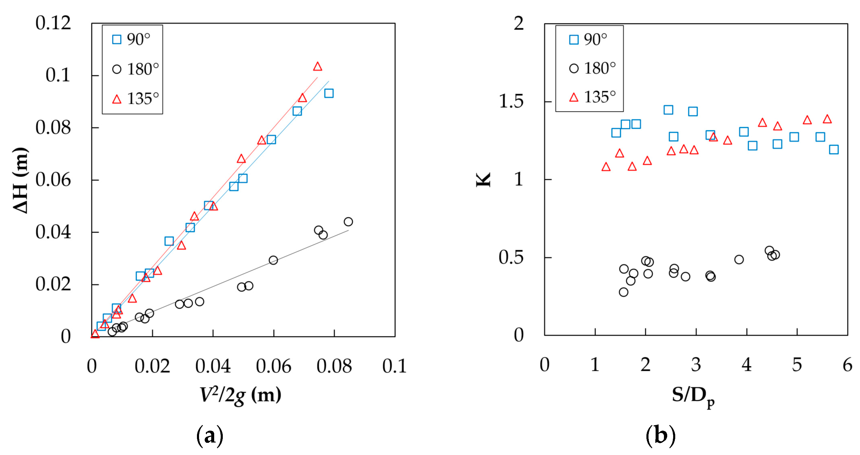
The experimental head losses for particular inflow directions for Type A manholes are displayed as head loss (ΔH) versus velocity head
(
Figure 6a). The head loss coefficients are the slope of the regression lines fitted to the experimental data. Additionally, the head loss coefficients were calculated with Equation (1) for every single solution. The head loss coefficients were found to be 0.48, 1.25, and 1.34 for 180°, 90°, and 135° respectively. The loss coefficient for the 180° connected manhole was smaller than an angled connection. It can be broadly divided into flows that collide directly with the downstream wall of the manhole without being affected by it, losing almost all of its kinetic energy. The 135° connection energy loss was higher than the 90° angled connections, since the jet flow negative effect on the outlet was distinctive.
Marsalek [
47] tested 180° connected manholes with three different molds using a manhole with D
m/D
p = 1.93, which was much smaller than the current experimental study. One of the tested flat-bottom manholes without a sump had a 0.208 head loss coefficient. The highest head loss, according to Stovin, Bennett, and Guymer [
50], was determined to be around 0.8 from CFD modeling. Similarly, Beg, Carvalho, and Leandro [
27] determined head loss coefficients around 0.4 at post-threshold surcharge from CFD modeling for D
m/D
p = 5. The result of the presented experimental study is compatible with the Beg, Carvalho, and Leandro [
27] CFD modeling.
Marsalek and Greck gave the experimental results of a 90° inflow pipe connection of a flat bottom without a sump zone. The energy loss coefficients of the manholes with diameter ratios Dm/Dp = 2.3 and 4.6 are 1.8 and 1.87, respectively, for a 90° pipe connection. The published results are higher than those of the current study.
Figure 6b shows the relationship between the ratio of the surcharge height inside the manhole to the pipe diameter and the energy loss coefficients. In the case where the inlet pipe is connected at 135°, the loss coefficients decrease as the ratio of the water height in the manhole to the pipe diameter and the pipe flow decreases. At high velocities, the jet striking closer to the manhole outlet pipe labels the flow in the outlet pipe and causes an increase in energy losses.
3.2. Type B Manhole Change in Head Loss Coefficients Due to Pipe Direction and Comparison with the Literature
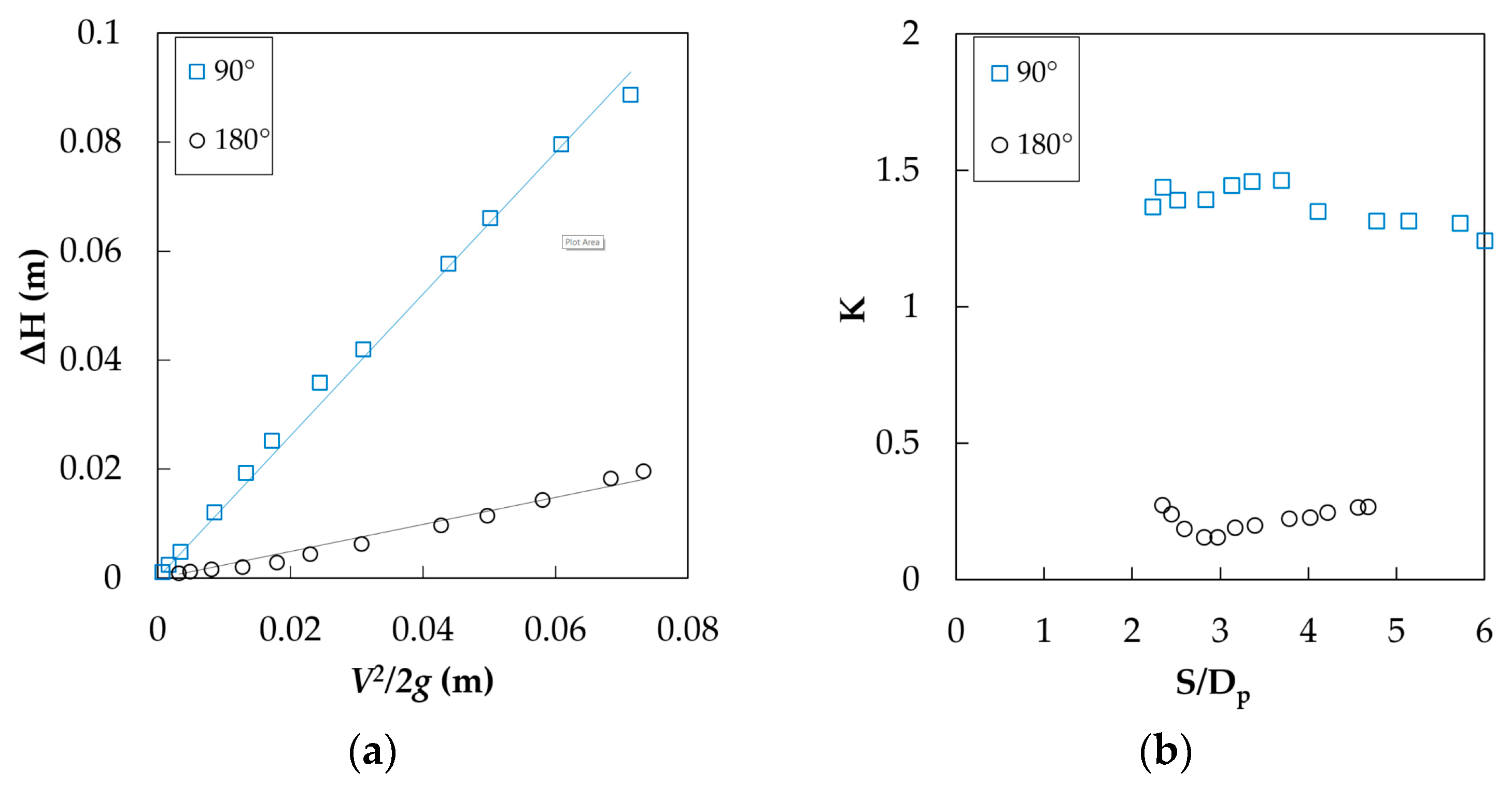
The experimental head losses for particular inflow directions for Type B manholes are displayed as head loss (ΔH) versus velocity head
(
Figure 7a). The head loss coefficients are the slope of the regression lines fitted to the experimental data. The head loss coefficients are 0.25 and 1.30 for 180° and 90°, respectively. The maximum and minimum values of head loss coefficient are 1.46 and 1.20 for a 90° pipe connection, and the maximum and minimum values are 0.27 and 0.16, respectively, for a 180° pipe connection.
Arao and Kusuda [
25] carried out experiments for pipe angles of 180°, 135°, and 90° for Type B half-bench manholes with D
m/D
p = 3.6. The energy loss coefficients varied between 0.1 to 0.6 for 180° connections in post-threshold flow conditions. For a 90° connection, the head loss coefficient varied between 1.0 and 1.8; for post-threshold flow conditions, the head loss coefficient was almost 1.4. Marsalek and Greck [
24] gave loss coefficients of the manholes with diameter ratios D
m/D
p = 2.3 and 4.6, which were 1.69 and 1.67, respectively, for Type B manholes connected with a 90° inflow pipe. The loss coefficients were almost constant for all surcharge height ratios where the inlet pipe was connected at 90° (
Figure 7b). However, the loss coefficients were slightly decreased at the surcharge ratio equal to three for a 180° connection.
3.3. Type C Manhole Change in Head Loss Coefficients Due to Pipe Direction and Comparison with the Literature
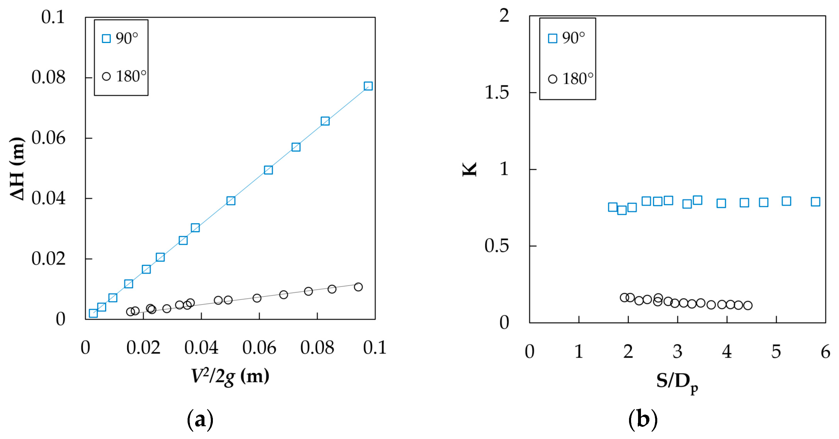
The experimental head losses for particular inflow directions for Type C manholes are displayed as head loss (ΔH) versus velocity head
(
Figure 8a). The head loss coefficients are the slope of the regression lines fitted to the experimental data. The head loss coefficients are 0.12 and 0.79 for 180° and 90°, respectively. The maximum and minimum values of the head loss coefficient are 0.80 and 0.73 for the 90 ° pipe connection and 0.17 and 0.11 for the 180° pipe connection, respectively. Marsalek and Greck [
24] gave loss coefficients of the manholes with diameter ratios D
m/D
p = 2.3 and 4.6, which were 0.97 and 1.12, respectively, for Type C manholes connected with a 90° inflow pipe. The loss coefficients were almost constant for all surcharge height ratios for both the 90° and 180° inlet pipe connections (
Figure 8b).
3.4. Head Loss Coefficients at Different Manhole Molds for 180° Pipe Connections
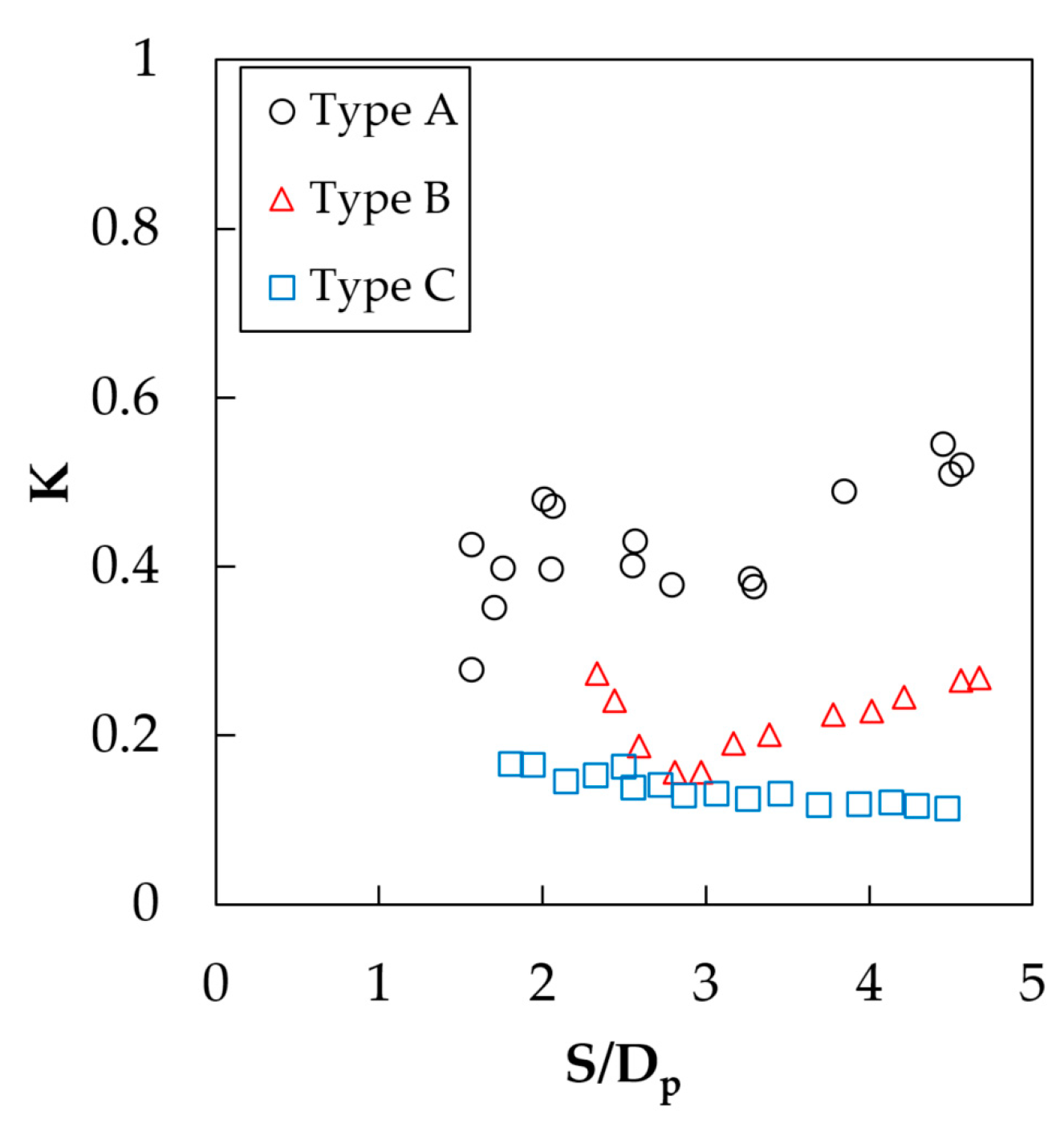
Figure 9 shows the measured surcharge ratios and head loss coefficients for the three distinct manhole mold types. In every scenario, the Type A manhole had comparable, more significant head loss coefficients than those of the Type B and Type C manholes. The head loss coefficients for Type A manholes varied between 0.3 and 0.6 for all inflow circumstances. It should be noted that if the manhole sump zone depth varies, the Type A findings may change. The circular jet was constrained by the benching in the manhole, which also reduced the head loss coefficient at high surcharge conditions. The Type B with a half bench on the bottom manhole head loss coefficients vary between 0.16 and 0.27 for different surcharge heights. The Type C manhole with a full-bench bottom gives minimum head loss coefficient, and the measured values for different flow conditions vary between 0.11 and 0.17.
3.5. Head Loss Coefficients at Different Manhole Molds for 90° Pipe Connections
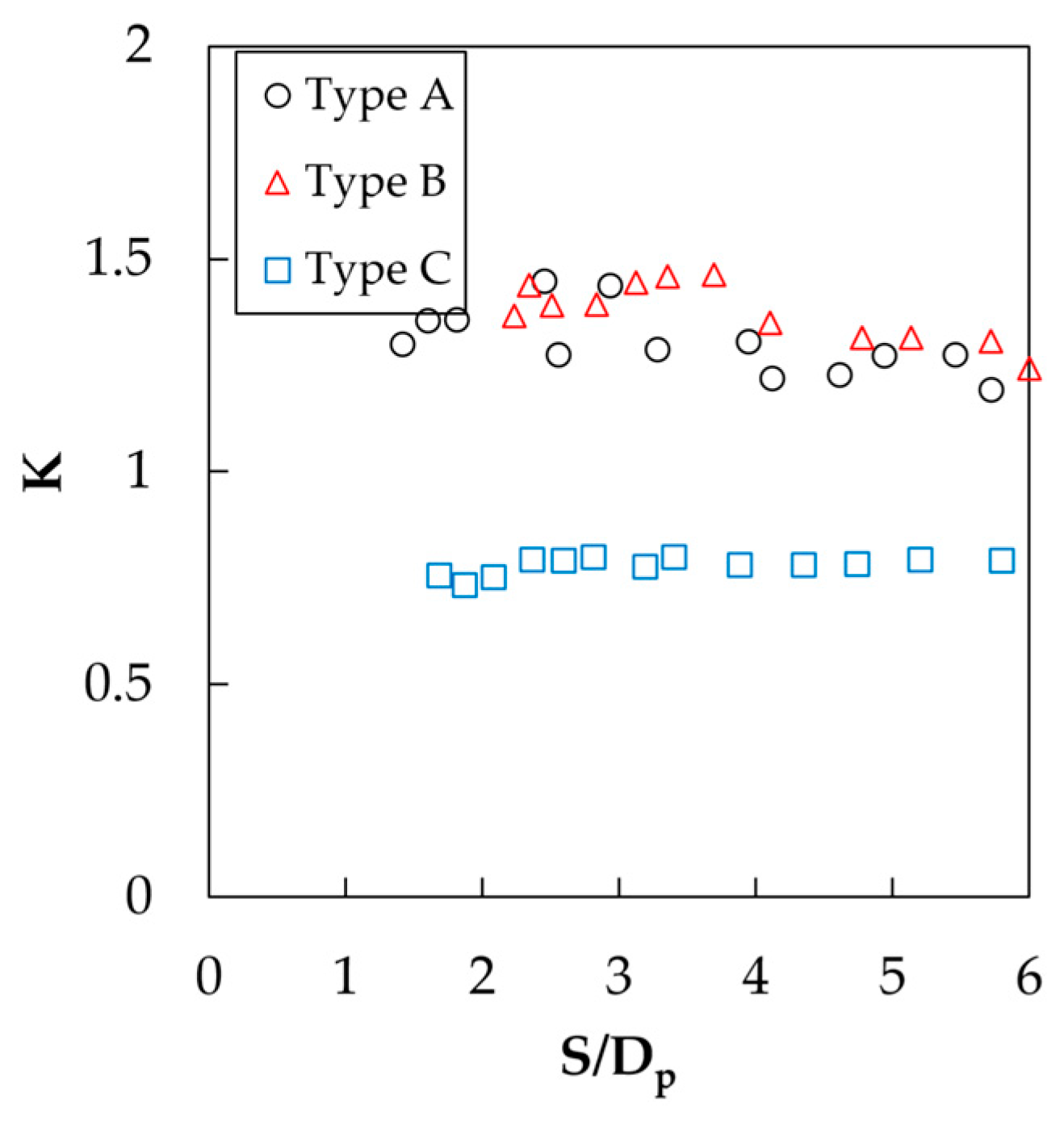
The reported manhole head losses were significantly impacted by manhole benching. The benching inside the manhole had the most impact on the head loss of all the experimental conditions examined (
Figure 10). The momentum of inflow is partially conserved, and the head losses are decreased by the manhole flow guiding applied on the bottom. The Type C manhole had better performance than Type A and B. The Type B manhole had no improvement on the head loss coefficients. The incoming stream was directed upwards by a half bench on the bottom, which resulted in significant turbulence and head loss at the confluence, according to detailed inspections of its functioning [
37].
3.6. Comparison of Experimental and Numerical Modeling Results
The CFD study consists of a numerical solution of all experimental molds and connection angles. Five different boundary conditions are applied within experimentally observed data in each case. The required values are extracted from the numerical solution. Similar to the experimental study, the head loss (ΔH) versus velocity head
are plotted, and the overall head loss coefficients K
fit are obtained from the fitted regression line. The K
min and K
max values are the minimum and maximum head loss coefficients calculated from Equation (1) for each run of the studied mold and connection angle. Each case’s experimental and numerical findings are tabulated for comparison (
Table 1). The overall fitted head loss coefficient values for all mold types are almost similar for 180° connections. However, for 90° and 135° pipe connections, the numerical model gives more significant head loss coefficients.
Especially in Type A and Type B manholes, the vortex inside the manhole becomes stronger when the current enters at 90° and 135°. The vortex formed in the manhole extends into the outlet pipe and causes spiral flow in the outlet pipe. The spiral flow in the outlet pipe affects pressure measurements and may increase the pipe’s energy loss and decrease the head loss of the manhole during the experiments study. In the experimental study, the pressure was measured from the boundary of the pipe wall, where the spiral flow was more effective than the center region. Oppositely, in the CFD study, pressure at the corresponding points was obtained from cross-section average values with less impact from spiral flow. This was for a Type C manhole, since the flow was guided with a full bench on the bottom. The force of the vortex is comparably smaller than that of the Type A and Type B manholes. When it comes to energy loss coefficient values, CFD results are more reliable than experimental results. Further studies are required to choose proper measurement points for experimental studies.
The connection angle and benching design had an impact on the head loss and drainage capacity of the two-way junction manhole, according to the physical model experiments in the preceding section. Thus, a numerical simulation was used to assess the significance of flow direction (inflow to outflow), which was not validated in the experiment, and the location and height of the vortexes in the manholes. The study of the two-way junction manholes’ flow patterns with different connection angles in flatbed manholes is shown in
Figure 11 as pathlines and velocity fields.
Figure 11a is a 3D pathlines plot colored according to the velocity magnitude of the 180° connection manhole without benching. The plot shows that the separation zone occurred in the simulation all around the jet stream. A low-velocity circular flow covers all water flow in a manhole—the velocity magnitude of the circular flow is less than 0.16 m/s. Additionally, the pipe center line horizontal plane velocity distribution shows the core and diffusion zones of jet flow (
Figure 11d). The core zone reaches the outlet pipe entrance while preserving its momentum. The uniformly developing diffusive zone is seen all around the jet, since there is no benching on the bottom. The circular separation zones on both sides of the jet diffusion cover all horizontal planes with a velocity of less than 0.16 m/s.
Figure 11b,e illustrates the 90° connection of the inflow pipe to the manhole. The analysis showed that although the inflow pipe is horizontally connected to the manhole, the jet gradually turns upward and forms large eddies in the manhole. The velocity of eddies in the manhole is between 0.5–1.0 m/s. The eddies inside the manhole occur on inclined planes, not in horizontal or vertical planes. They follow the manhole wall and water surface and move towards the inside of the outlet pipe, narrowing their turning diameter. The eddies move into the outlet pipe, and a spiral flow in the outlet pipe is observed. The resulting vortex structure prolongs the residence time of the fluid in the manhole, ensures complete mixing, and may cause air suction at low water levels [
30].
Figure 11e shows the pipe centerline horizontal plane velocity distribution. After entering the manhole, the jet flow loses momentum, and the diffusion zone rapidly grows. While the maximum flow speed of the inlet pipe in the 90° connected manhole is 1.434 m/s, the maximum flow speed in the contracted region of the outlet pipe reaches 1.654 m/s.
Figure 11c,f shows the 135° inflow pipe connection pathlines and pipe centerline horizontal plane velocity field. The eddies form on an inclined plane and cover all water bodies in the manhole. The velocity of the eddies in the manhole is between 0.3–0.7 m/s. The jet flow affects the outlet pipe flow and the velocity in the outlet pipe. The eddies move into the outlet pipe, and a spiral flow is formed in it. While the maximum flow speed of the inlet pipe in the 90° connected manhole is 1.434 m/s, the maximum flow speed in the contracted region of the outlet pipe reaches 1.654 m/s.
The velocity profiles of the three types of 180° manholes are given in
Figure 12. The diffusion region in the Type A manhole expands in all directions, and the core region loses its energy (
Figure 12a). On the contrary, the benching in the Type C manhole jet is confined, and the diffusion region is seen only in the upper part with a more significant velocity and cross-sectional area (
Figure 12c). The jet effect reaches the surface. The same condition can also be observed with a small effect in the Type B manhole (
Figure 12b).
4. Conclusions
The work given in this research examines the head loss coefficients and surcharged two-way manhole hydraulics as a result of different adjustments to their parameters. The relationship between the head loss coefficients and the effluent flow discharge, benching floor arrangement, and surcharge ratio is studied on a 1/5 scale experimental setup with manholes and pipelines. The software Ansys 14.5 FLUENT solver was used to simulate the manholes numerically.
Surcharged manhole molds of three different kinds were tested: Type A, which had a flat bottom, lacked a guided channel, and had a sump zone below the inlet–outlet pipe invert level; Type B, which was half-bench; and Type C, which was full-bench as a U-shaped invert guided channel at the manhole bottom. The manhole-to-pipe diameter ratio for each of the three manholes was 5.3. In the post-threshold surcharged conditions, the variation in the head loss coefficients was comparably tiny for all molds and connection orientations.
The loss coefficients obtained from the numerical and experimental study are in good agreement for all types of 180° connected manholes. However, for the 90° and 135° pipe connection orientations, the head loss coefficients obtained from the numerical model are larger than the experimental result in an approvable range.
In the manholes with 90° and 135° connections, the eddies entirely cover the inside of the manhole. The eddies formed inside the manhole and the velocity distribution in the outlet area cause spirals and a nonuniform velocity distribution in the outlet pipe. The complex flow structure inside the outlet pipe may cause differences in measurements.
The Type C full-bench manhole showed the best performance under all flow conditions. Reducing the head loss coefficients will enable the network to operate more efficiently in case of a surcharge.
With numerical modeling, the flow conditions inside the manhole and the flow structures in the outlet pipe have been revealed. In future studies, it will be useful to experimentally examine the flow structure in manholes with 90° and 135° pipe connections.
