1. Introduction
The three main types of losses in irrigation canals are water seepage from the canal’s sides and bed, losses of evaporation from the open surface of the channel’s top width, and transpiration losses from weeds and grass. The author in [
1] suggested using an approach to calculate bed width and water depth using known discharge, side slope, longitudinal slope, Manning’s coefficient, evaporation rate, and soil type. To guarantee that the irrigation system works properly and that water is used efficiently, these losses must be decreased. Unlined canals are used to replenish groundwater through seepage, while lined canals are mostly used to stop water seepage through the soil. The transmission losses between the stream and the underlying aquifers were examined using the reach length water balance (RLWB) method [
2]. In [
3], the outcomes of a numerical simulation used to examine the factors that contribute to seepage from earthen channels were evaluated. The performance of irrigation schemes is impacted by a number of variables, including planning, design, construction, facility operation, maintenance, and water application [
4]. For example, equity [
5,
6,
7], adequacy [
8,
9], productivity [
10,
11], sustainability [
12,
13], and flexibility [
14] are just a few of the indicators that researchers have used to assess the performance of irrigation schemes. In many studies, characteristics of performance indicators have been introduced and analyzed. Water availability [
15], profitability [
16], resiliency [
17], timeliness of irrigation [
18,
19], irrigation intensity [
20], and regularity [
21] have all been studied.
Canal lining can be defined as adding a layer of impermeable material over the excavated surface of the canal to minimize the leakage of water into the surrounding soil. In cases where the canal lining is on the side slope of the canal, it should be stable enough to protect the lining layer from excessive lateral forces. The probable technical and environmental effects of such a national project were discussed by authors in [
22]. Lining 30% of the early section of watercourses led to an average yearly water savings of 10.32 ha-m, according to [
23]. The author in [
24] provided a method for selecting the best seepage-control lining for canals based on optimal performance levels and calculations of the present rates of various types of traditional (concrete monolithic and reinforced concrete prefabricated) and geosynthetic (geomembrane, geocomposite) coatings. In [
25], researchers studied the competence, equity, efficiency, and dependability indices to determine how well water delivery performed in a western Turkish irrigation network. Regarding competence, equity, confidence, and dependability, the water supply performance of the analyzed canals was rated as inappropriate in each irrigation season. The physical structure and the management section are where these difficulties’ root causes can be found, according to an analysis of the spatial and temporal dimensions of these indices. The authors in [
26] demonstrated that the hydraulic characteristics of the liner had a significant impact on the amount of seepage. The most effective liners were concrete, geo-membrane, and bentonite; in the absence of pumping, these percentages would be around 99%, 96%, and 54% via wells from the aquifer, respectively.
Both lined and unlined canals have been investigated by a huge number of authors. Those in [
27] investigated how the Al-Hagar Canal’s lining affected the flow characteristics and compared the canal’s before- and after-lining conditions. Al-Hagar Canal water losses were 38.74% when unlined but fell to 29.25% when lined. In a particular region of Pakistan’s Indus Basin, the differences in water losses caused by lined and unlined streams were evaluated [
28]. The lining was found to have reduced water loss by 22.5%. The maximum water losses from canal networks are from seepage losses. If the soil of the canal ensures higher losses, canal lining is the most suitable and applicable solution. According to [
29], the two precast concrete slabs’ joint cracks and the geomembrane’s perforations were to blame for the increasing seepage loss. The combination of fresh concrete and geomembrane lining decreased seepage by 86% when compared to unlined canals; after three years of operation, the combination could still reduce seepage by 68%. The author in [
30] indicated that three case studies have been simulated and compared, including unlined, lined, and lined canals with a drainage pipe. The results demonstrate that irrigation canal rehabilitation has decreased the losses from canals, resulting in lowering the groundwater, where the case of lining gave a higher reduction than the case of lining with a drainage pipe.
Economically viable changes in the operation and management of irrigation systems have been the subject of extensive research. One such study [
31] laid the foundation for utilizing performance assessments to enhance irrigation services. Furthermore, researchers have delved into the utilization and challenges associated with canal models [
32]. They identified three key factors—distance, time-step, and weighting parameters—that were hypothesized to impact the model’s output accuracy. The modelling of open channel flows holds paramount importance in hydraulic and irrigation engineering. Numerous investigations have focused on simulating flow in single channels or open channel networks. Examples include studies using a 2D curvilinear grid [
33,
34], a 2D numerical model for sediment transport in alluvial shallow-wide streams in the River Nile [
35], the simulation of open channel network flows employing a finite element approach [
36], and the simulation of a sub-critical flow at open-channel junctions [
37]. Additionally, a 1D model was verified through comparisons with the outputs of the 1D SOBEK model of the El-Mahrousa Canal [
38]. The SOBEK model serves a vital role in decision-making for significant river projects, daily river level forecasts, realistic high-water level assessments for safety evaluations, and salt intrusion calculations during dry seasons.
Given that SOBEK is a 1D model, its applicability is restricted to problems with negligible 2D or 3D impacts; it may be used to conduct studies on flood mitigation, canal system development, river dredging methods, and salt intrusion at lower levels of rivers. Some of these models should occasionally be modified to incorporate specific operational parameters or irrigation system architecture that are not represented in the model. In case studies, these models were commonly applied by many scholars (e.g., [
39,
40,
41,
42,
43,
44,
45,
46,
47,
48,
49]). Egypt’s growing population, along with municipal and industrial needs, has led to water shortages.
Due to the growing need for irrigation water and the limited water resources, it is imperative for irrigation systems to enhance their dependability and effectiveness in the coming years, according to [
50,
51]. This necessity has drawn the attention of decision-makers keen on improving irrigation system efficiency. To address this, this study opted to reconstruct a natural canal, complete with its functional cross-sections, and compare it to the restored canals within Egypt’s canal networks. This choice was driven by the lack of available data. Employing this approach facilitates the prediction of the water, environmental, and financial outcomes of the NPCR.
This study involved simulating the water surface profile in a canal affected by flow conditions. Specifically, the Western Meleg Canal in Menoufia, Egypt, was chosen as part of an irrigation network restoration plan due to its strategic location near the vital Shebeen-Berket Al-Sabaa Road. However, a segment of this canal, spanning from 1500 to 3400 km, faced challenges in implementing a concrete lining due to nearby buildings that could not be removed. Consequently, two scenarios were examined: narrowing the canal width and covering this problematic stretch. These scenarios underwent hydraulic and cost assessments. This study included a hydraulic analysis of the current state of the canal’s restoration issues using a hydraulic model. It also examined the rehabilitation design for various components, including dry pitching, concrete work, and covering. Additionally, the impact of these scenarios on water levels and flow velocities along the Western Meleg Canal was investigated.
2. Description of the Study Area
The Western Meleg Canal branches from the Bahr Shebin Canal in front of Regulator km 53.500; the canal inflows through two gates on the Bahr Shebin Canal; the width of the opening is 3 m; and the canal serves a total area of (44.1 × 10
6) m
2. The discharge of the canal ranges from 200,000 to 250,000 cubic m per day. It extends on the right side of the Western Meleg Canal, along the Shebin Al-Kom-Berket Al-Saba road, for a distance of 1.500 km; then, the road goes away from it after 1.500 km, and it is parallel again at 2.900 km and extends parallel to the right side until the end of the canal, which is 6.230 km long. There is a parallel road on the left mainland of the canal starting at 1.500 km. The canal passes through a large population block on the right and left sides (the village of Meleg). The Western Meleg Canal feeds three canals: the Maqtaa Shamma Canal, which takes water on the left side at 2.600 km and extends 8.680 km to serve (7.98 × 10
6) m
2; the Al-Ghouri Canal, which takes water on the left side at 6.200 km and extends 13,680 km to serve (22.26 × 10
6) m
2; and the Al-Halfaya Canal, which drains the Western Meleg Canal (end of the canal) and extends for a length of 5.950 km to serve (7.14 × 10
6) m
2.
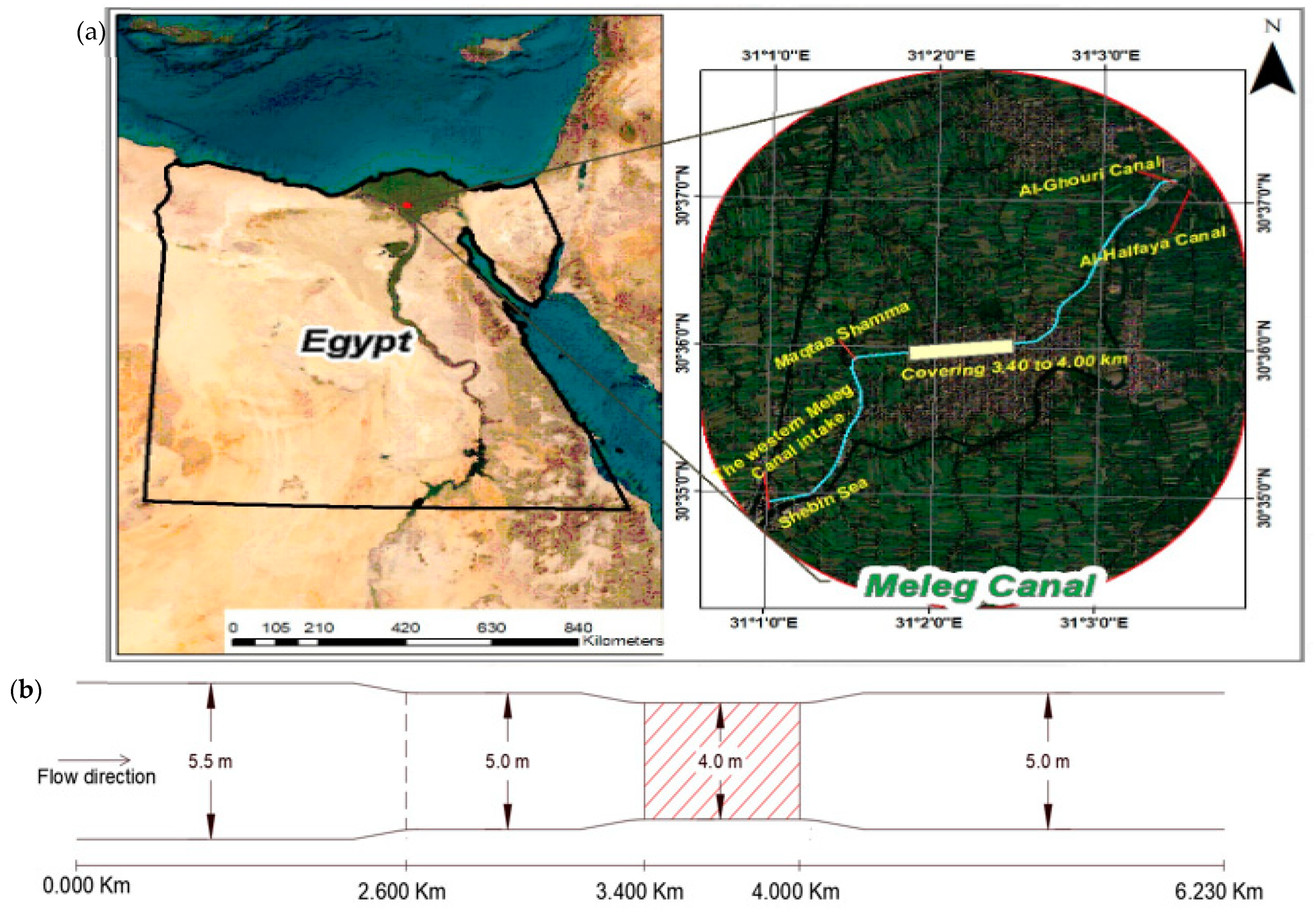
Figure 1a shows the location of the region of the Western Meleg Canal, as well as the locations of the Maqtaa Shamma, Al-Ghouri, and Al-Halfaya Canals.
Figure 1b shows a graph of cross-sectional changes along the canal; the hydraulic and design data of the canal are shown in
Table 1, and since the Western Meleg Canal is located within the national project for the lining and rehabilitation of canals, the design sector for lining these canals is (30 cm Big Cobbles + 10 cm plain concrete).
It is clear from the design data of the Western Meleg Canal that the bed width is 5.50 m in the distance from the intake to 2.600 km, and the slope of the bed in this distance is 8 cm/km. While the bed width is 5.0 m in the distance from 2.600 km to the end of the canal and the design of the slope bed in this distance is 7 cm/km, side slopes along the length of the canal are 1:1. There is a box section with one vent, a bed width of 4.0 m, and a height of 2.30 m on the canal. This coverage is located in the distance from 3.400 km to 4.000 km; at some distances along the canal, there are vertical retaining walls on the left bank.
3. Numerical Model
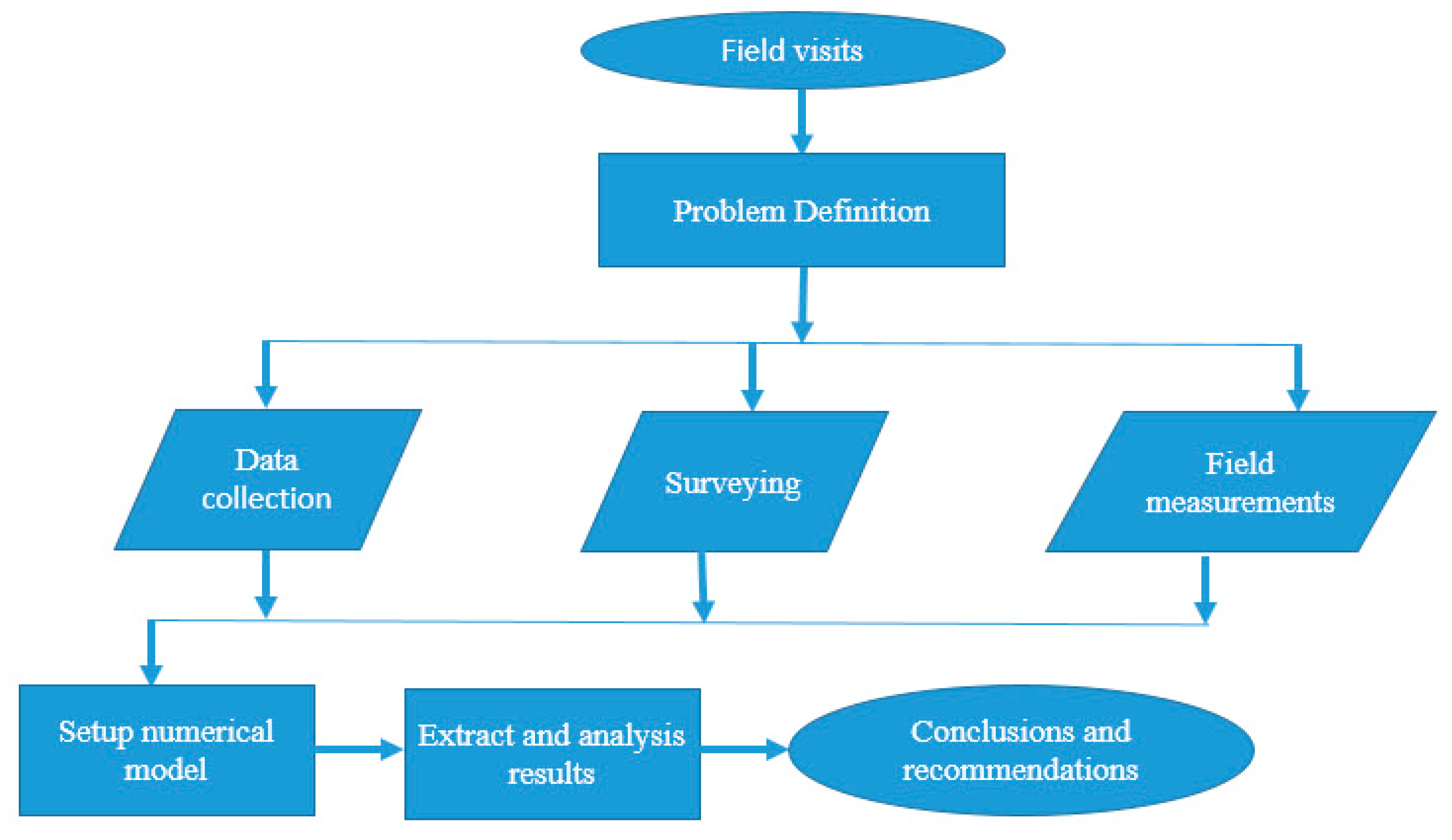
Figure 2 illustrates the research methodology employed. Hydraulic modelling was employed to assess the impact of two factors: narrowing the bed width and covering the Western Meleg Canal segment from 1500 km to 3400 km. Given that lining work had commenced on the canal, the current canal conditions were simulated using design cross-sections, and model variables were adapted to the non-lined distances. Moreover, the study examined the canal’s status after the lining process and its condition following bed width reduction and coverage.
SOBEK-1D was the primary modelling tool employed throughout this investigation due to its versatility in accounting for various local-scale factors. This model possesses the capability to handle complex canal configurations, including variable cross-sectional shapes, as well as simulate the flow within extensive canal networks featuring numerous lateral off-takes and hydraulic structures, such as weirs and culverts. SOBEK was selected for modelling the drainage system because of its high adaptability to adjusting Manning’s coefficient value, a critical parameter. The foundation of SOBEK-1D relies on the Saint-Venant equations, which are rooted in continuity and momentum principles. They are a collection of equations that describe the dynamic behavior of irrigation canal networks that are frequently useful:
where the discharge is
Q, the longitudinal distance along the channel in the direction of flow is
x, time is
t, water surface width is
W, water depth is
H, the bed slope of the channel is
S0, the slope of the energy grade line is
Sf, and the gravitational acceleration is
g.
According to [
52], the flow in SOBEK-2D is described by fundamental equations that encompass three key components: the continuity equation, the momentum equation for the
x-direction, and the momentum equation for the
y-direction used in [
46]. The continuity equation is expressed as follows:
where velocity in the
x-direction is
u, velocity in the
y-direction is
v, and water level above the plane of reference is
ξ. For two-dimensional flow, two momentum equations were calculated, together with the continuity equation. The momentum equations can be written as follows:
where velocity magnitude
V = (u
2 + v
2)
0.5, the Boussinesq coefficient is
α, gravitational acceleration is
g, and the Chezy coefficient is
C. The Delft scheme was used to numerically solve these equations. This method uses a staggered grid to solve the De Saint-Venant equations in [
52]. The connection nodes and calculation points in this staggered grid define the water levels, whilst the intermediate reaches or reach segments define the discharges.
A numerical model was created for the entire length of the Western Meleg Canal, which reaches a length of 6.230 km. All the intakes on the canal were represented, including the Maqtaa Shamma Canal km 2.600, the Al-Ghouri Canal km 6.200 and the Al-Halfaya Canal 6.230 km. The numerical model was designed using the design cross-sections and data of the structures built on the canal. For the water levels and the discharges at the boundaries of the canal (boundary conditions), the hydraulic model was designed based on the maximum discharge passing through the canal (2.89 m
3/s), and the Manning’s coefficient (n) was used (n = 0.03 s/m
1/3) before the lining according to the unlined distances based on model calibration by the field data. Manning’s coefficient was used (n = 0.018 s/m
1/3) for the case after the lining according to the Ven Te Chow tables and the previous experiences in lining. The water levels and velocities along the canal were deduced for all the study scenarios.
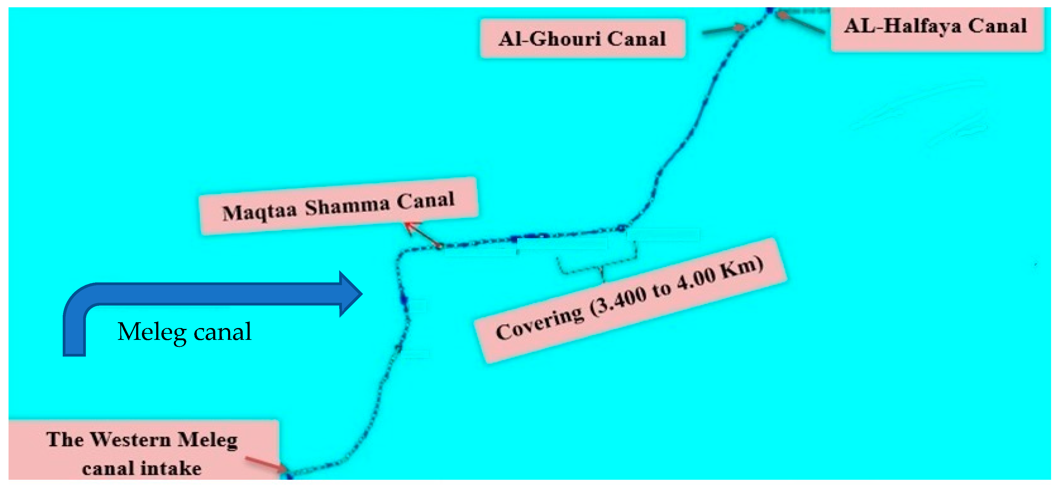
Figure 3 shows a plan of the Meleg Canal on the numerical model.
Model Calibration
Calibration is the process of adjusting the input parameters of the model until obtaining results that match the field measurements. Several runs were performed to achieve the best agreement between measured and computed values from the model. This was carried out by adjusting roughness coefficients along the modelled canal. The downstream river reaches can be well simulated using a coupled one-two-dimensional (1D-2D) flow model. Thus, a model was schematized based on the numerical SOBEK software package [
52], which is the 1D analysis along the modelled canal and the 2D unsteady formulations of the full dynamic equations along overland water flooded flow.
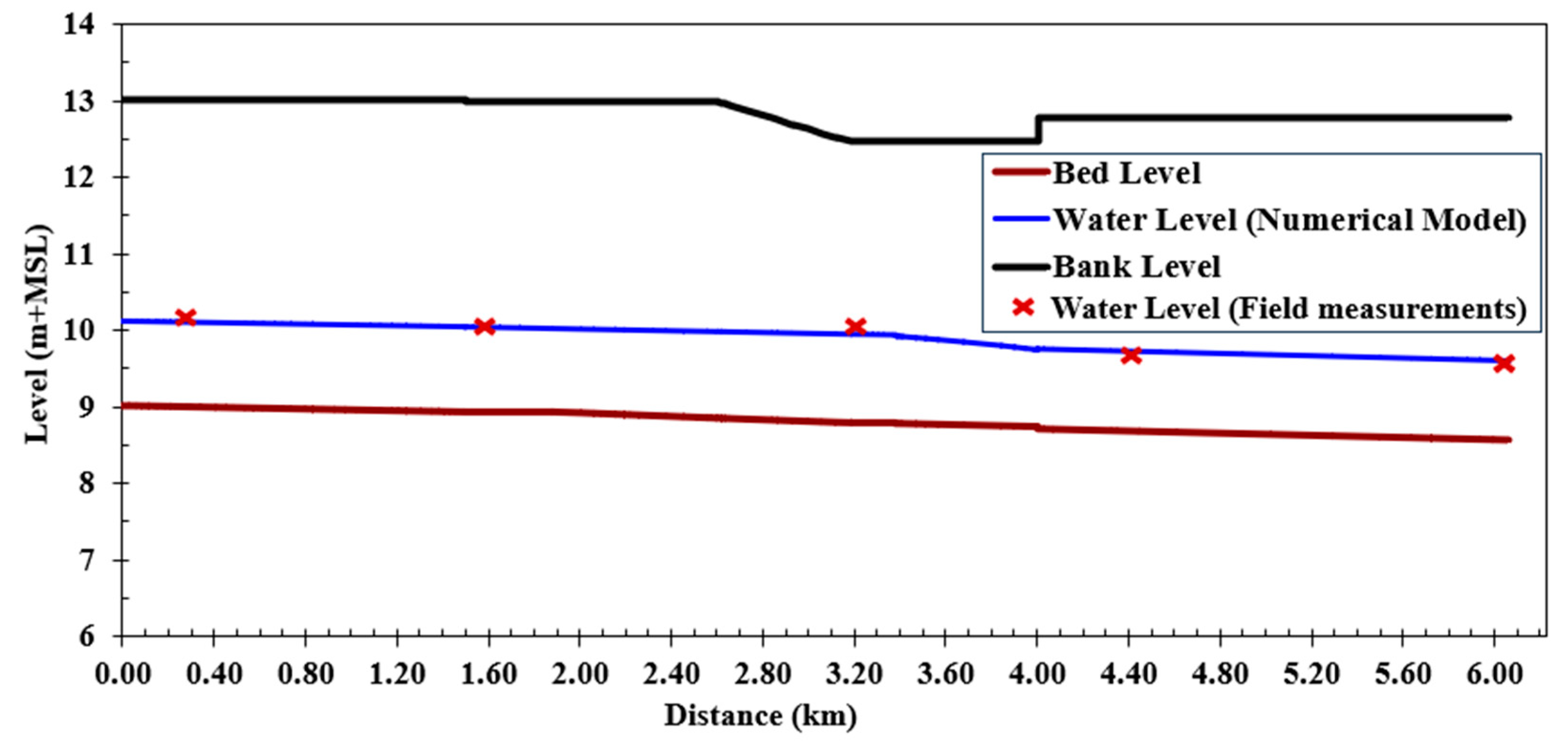
In this calibration, the Western Meleg Canal’s maximum discharge was reached, and the design cross-sections were used before the lining work. In
Figure 4, the Manning coefficient of soil was established at a value of 0.03 based on the field data, which were achieved using the SOBEK model. The water levels along the canal were observed if all the intakes were shut off. As shown in this figure, they ranged from 10.35 m at the beginning to 9.62 m at the end and are very close to the design water level for the canal. On the coverage, there is a 9.8 cm difference in water pressure, and the coverage operates in free flow. The canal’s water depths range from 1.06 to 1.34 m, and its flow velocities range from 0.36 to 0.62 m/s.
4. Results
The numerical model of the Western Meleg Canal was executed after inputting all relevant data, and it utilized Manning’s coefficient values for four distinct scenarios. These scenarios were evaluated using the designated cross-sections. The maximum canal discharge observed was 2.89 m3/s in three cases: (a) in the absence of water withdrawal from side intakes along the canal; (b) with the closure of the intake at the Maqtaa Shamma Canal (at 2.600 km), while the intakes at the Al-Ghouri Canal (at 6.210 km) and Al-Halfaya Canal (at 6.230 km) were operational; (c) with the operation of all intakes along the Western Meleg Canal, including the Maqtaa Shamma Canal, Al-Ghouri Canal, and Al-Halfaya Canal.
4.1. First Scenario (Runing the Canal Model without the Lining)
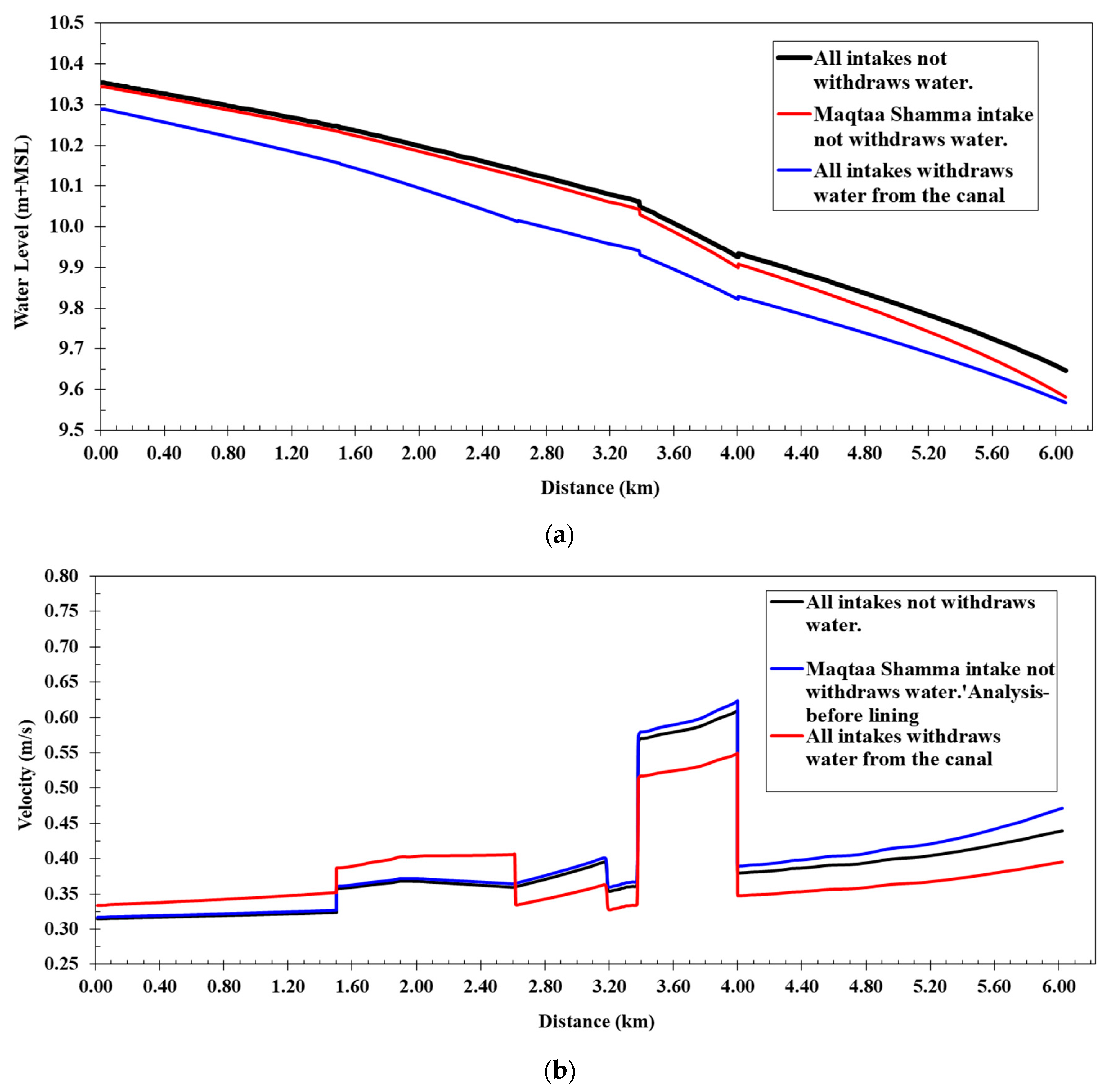
Figure 5 shows a comparison between the water levels of the cases of operation (a, b, and c) along the Western Meleg Canal before lining, the Manning’s coefficient value of 0.030, and a comparison between the flow velocities of the cases of operation along the canal. The comparison of the water levels revealed that the highest water levels occurred at the passage of the maximum discharge, and without operating the intakes, the lowest water level appeared when all the intakes were operating on the canal, where the water levels ranged from 10.29 m at the beginning of the canal to 9.54 m at the end of the canal, and the flow velocities ranged from 0.33 to 0.55 m/s, which reduced the water pressure difference on the coverage to 6.7 cm. In the second case, the Maqtaa Shamma Canal was closed, but the Al-Ghouri and Halfaya Canal intakes were operating. The water levels ranged from 10.34 m at the beginning of the canal to 9.54 m at the end, flow velocities along the canal in this case ranged from 0.34 to 0.61 m/s, and the water pressure difference on coverage was less than when all intakes were closed, at 8.8 cm.
4.2. Second Scenario (Runing the Canal Model with the Lining)
In this scenario,
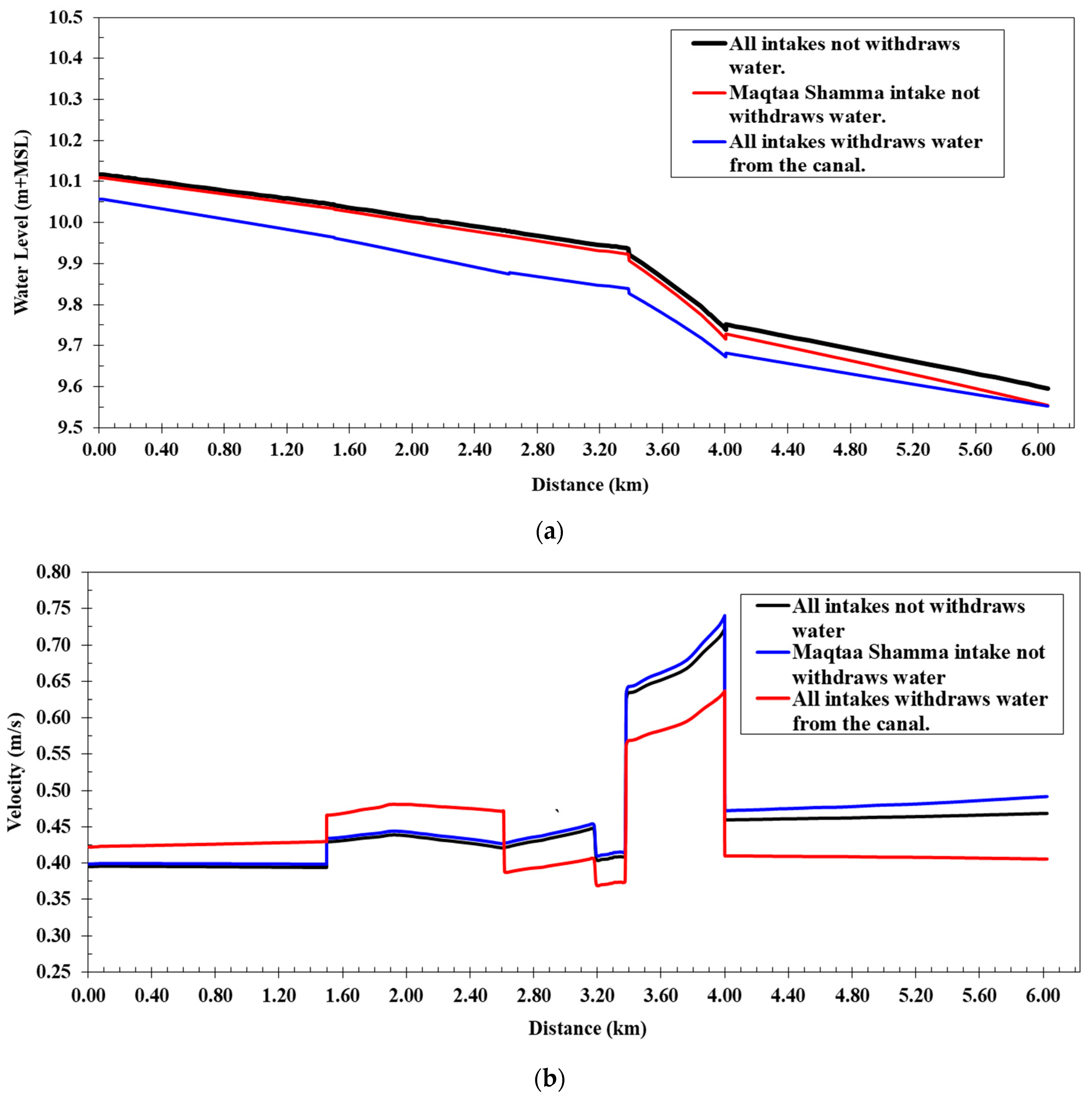
Figure 6a shows a comparison between the water levels of the cases of operation (a, b, and c) along the Western Meleg Canal after lining and shows that the water levels along the canal, as inferred from the numerical model, varied from 10.12 m at the beginning of the canal to 9.58 m at the end. They were lower than the water levels before lining to increase the velocity after the lining works. The flow velocities along the canal ranged from 0.39 to 0.72 m/s, and the water depths in the canal varied from 1.02 m to 1.16 m. The water pressure difference increased the coverage to 13.9 cm, and the coverage was still under free flow when the maximum discharge of the Western Meleg Canal was passed. The canal’s design cross-sections were used after lining works with a Manning roughness coefficient of 0.018, and the water levels along the canal were calculated if all canal intakes were closed.
Figure 6b shows a comparison between the flow velocities of the cases of operation along the canal. It is clear from the comparison of the water levels that the maximum water levels occurred when the maximum discharge was passed and without operating the intakes. The flow velocities along the canal in this case ranged from 0.37 to 0.64 m/s, and the water pressure difference on the covering was less than 11.14 cm. Water levels ranged from 10.11 m at the beginning of the canal to 9.54 m at the end when the Maqtaa Shamma Canal intake was closed and only the Al-Ghouri and Al-Halfaya Canal intakes were operating. In this case, the flow velocities along the canal ranged from 0.40 to 0.74 m/s. The maximum velocity appeared at the entry to the coverage if the difference in water pressure on the coverage was 14.83 cm. The speeds rose, and the water depths reduced, as compared to before and after lining. Thus, when lining the canal, the width needs to be reduced to maintain the canal’s water level.
4.3. Third Scenario (Runing the Canal Model after Contraction the Bed Width)
The hydraulic model of the Western Meleg Canal was run using the cross-sections of the design after the lining works and the contraction for the bed width in a distance from 1500 km to 3400 km, so that the bed width in this distance was 4.00 m and the maximum discharge of the canal was 2.89 m3/s. The width proposed for the bed, which was 4 m, was greater than the critical bed width, according to the specific energy equations.
The energy equation was applied between the two sections along the canal in which the bed was gradually contracted (15:1) from b
1= 5.50 m to b
2 = 4.0 m, as shown in
Figure 7. The application of the energy equation gives the following:
where
E is the specific energy,
HL is head losses, y is the water depth,
Q is the discharge, g is the gravitational acceleration,
A is the cross-section area, and the subscripts 1 (b
1 = 5.50 m) and 2 (b
2 = 5.50 m) denote the two successive
Section 1 and
Section 2.
Figure 8a shows a comparison between the water levels of the operating cases (a, b, and c) along the Western Meleg Canal after lining works and the contraction of the bed width in the distance. It also shows that the water levels along the canal, as inferred from the numerical model, varied from 10.16 m at the beginning of the canal to 9.59 m at the end of the canal; the flow velocities along the canal ranged from 0.37 to 0.72 m/s; and the water depths in the canal varied from 1.03 m to 1.17 m. The pressure difference between the coverage was 13.89 cm, and the coverage was still under free flow when the maximum discharge of the Western Meleg Canal was passed. The designed cross-sections of the canal were used after the lining works with a Manning coefficient of 0.018, causing the canal bed width to be 4.0 m in the distance from 1.500 km to 3.400 km. The water levels along the canal were deduced in case all outlets on the canal were closed.
Figure 8b shows a comparison between the different flow velocities of the operating cases along the canal. It is clear that the maximum water levels occurred at the passage of the maximum discharge and without the operation of all intakes. The lowest water level occurred when all intakes were operated on the canal, as the water level range in this case was from 10.10 m at the beginning of the canal to 9.54 m at the end. In this case, the water velocity along the canal varied between 0.40 and 0.64 m/s, and the differential in water pressure on the coverage decreased by 11.13 cm. As for the closure of the Maqtaa Shamma Canal intake and the operation of Al-Ghouri and Al-Halfaya Canal intakes, the water levels ranged from 10.15 m at the beginning of the canal to 9.55 m at the end of the canal,; the flow velocities ranged along the canal in this case from 0.38 to 0.74 m/s; and they increased. The difference in water pressure on the coverage was 14.84 cm, where, in this case, the maximum water velocity was at the entrance of the coverage.
4.3.1. Studying Effect of Contracting the Bed Width (4.0 m)
When the maximum discharge in the Western Meleg Canal was determined using the design cross-sections of the canal after the lining works with a Manning coefficient of 0.018, the water levels and velocities along the canal were compared for the canal lined without contracting the bed width (5.50 m) and the canal lined with contracting the bed width (4.0 m). In the distance, from 1500 km to 3400 km, for the two cases: (1) all intakes on the Western Meleg Canal were operated, and (2) there was no water withdrawal from the side intakes of the canal.
- (1)
Operating all intakes on the Western Meleg Canal
The study examined the operation of all intakes along the Western Meleg Canal, including the Maqtaa Shamma Canal, Al-Ghouri Canal, and Al-Halfaya Canal.
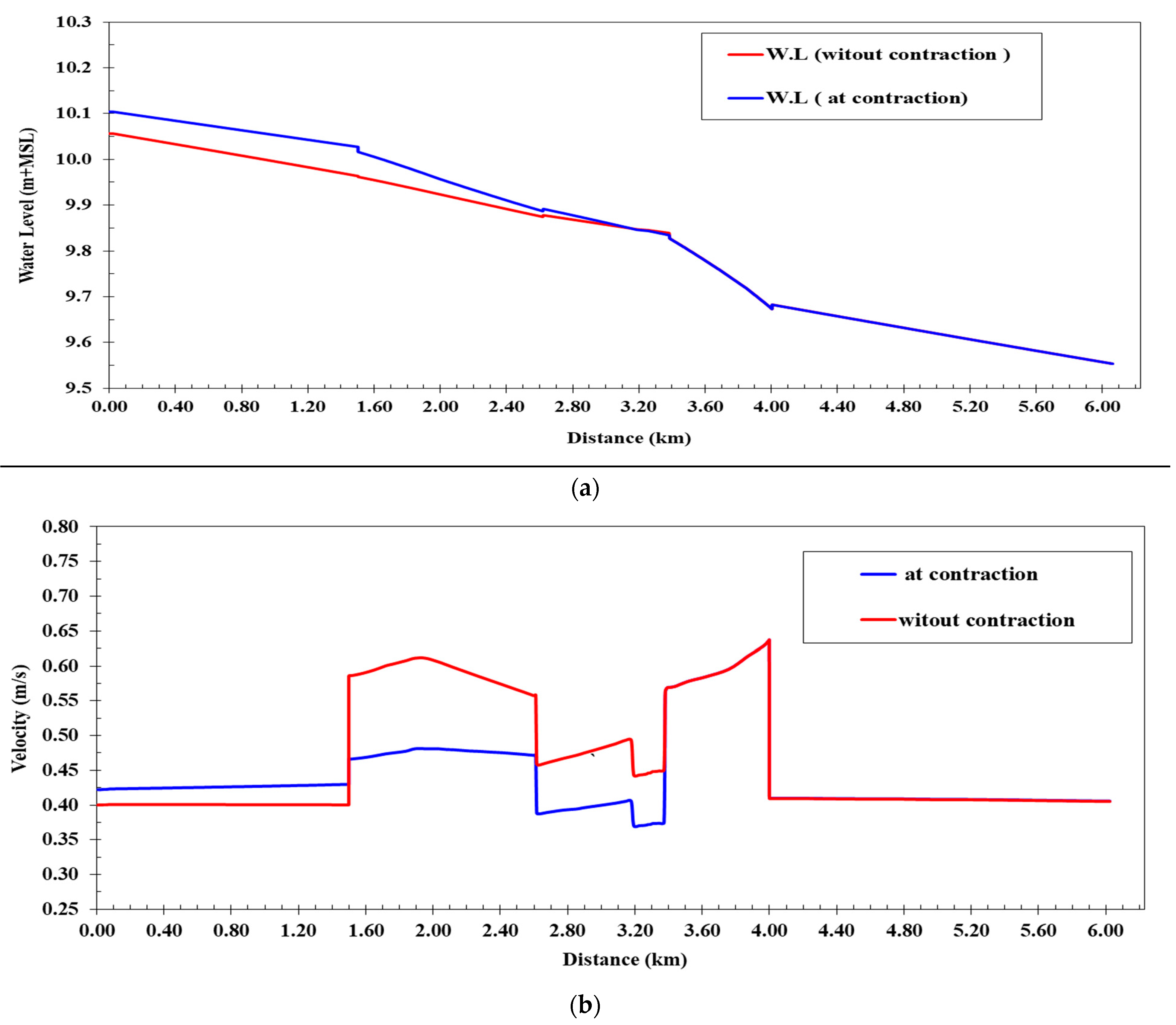
Figure 9a provides a comparison of water levels in the lined canal before and after narrowing the bed width in the specified stretch. Interestingly, there was stability in water levels from 3400 km to the end of the canal at 6230 km, as the coverage width at 3400 km matched the post-contraction bed width (4.0 m). However, a modest increase in water levels, ranging from 2 cm to 6 cm, occurred only in the segment from the intake up to 2600 km compared to levels before the bed width reduction.
Figure 9b presents a comparison of flow velocities in the lined canal before and after the bed width contraction. Similar to the water levels, flow velocities remained stable from 3400 km to the end of the canal at 6230 km. The bed width contraction led to a slight rise in water levels coupled with a decrease in water velocity of 0.023 m/s in the stretch from the intake to 1500 km. However, water velocity increased by 0.13 m/s in the span from 1500 km to 2600 km compared to pre-contraction velocity levels. Overall, the maximum water velocity post-bed width contraction reached 0.64 m/s, well within acceptable limits.
There was no water withdrawal from the side intakes of the canal.
This study examined the complete closure of all intakes along the Western Meleg Canal, with no withdrawal of water.
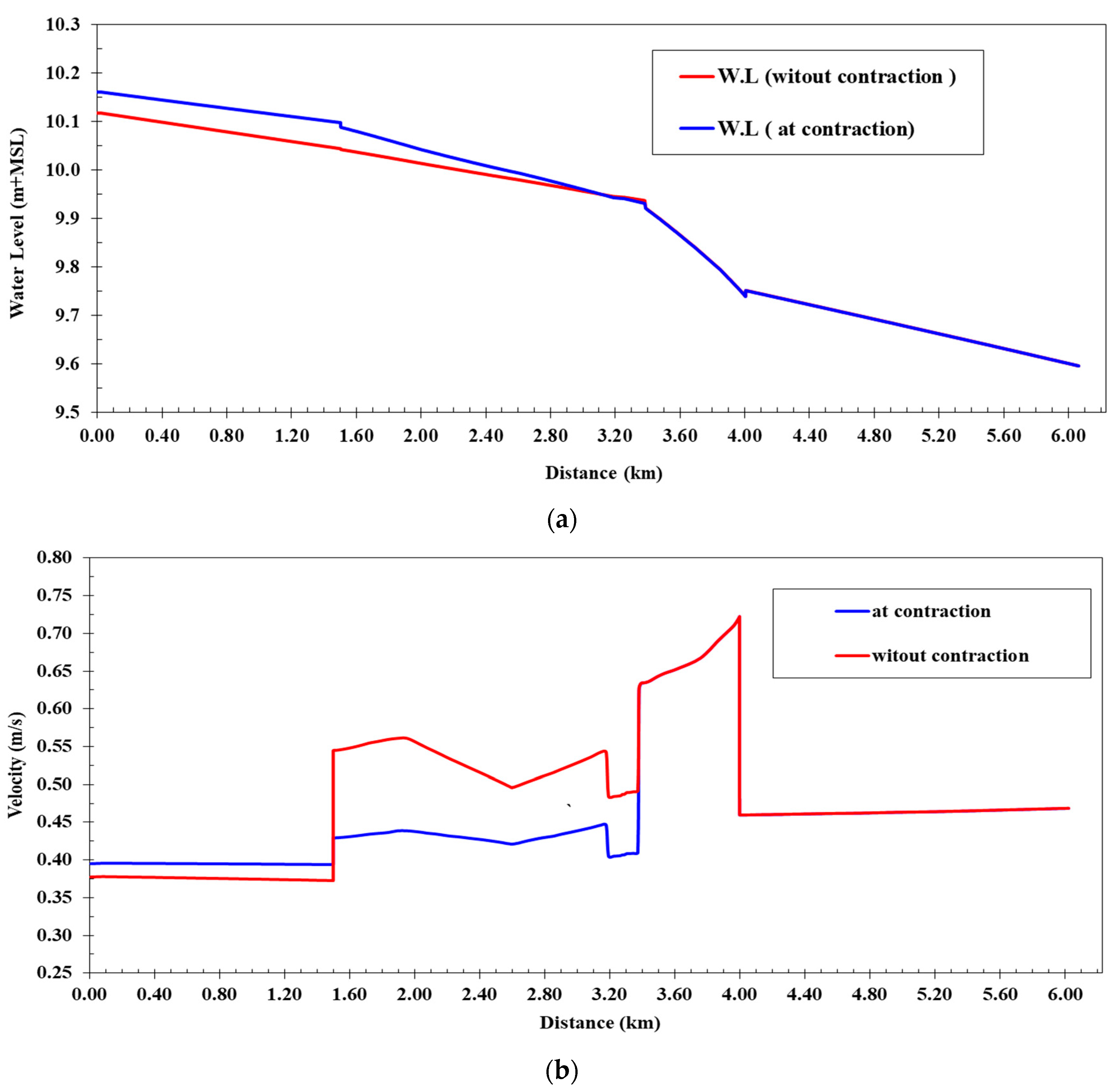
Figure 10a provides a comparison of water levels in the lined canal before and after the bed width was narrowed at the specified distance. Interestingly, water levels remained stable from 3400 km to the end of the canal at 6230 km, both before and after the bed width contraction. However, as a result of the bed width reduction, there was a modest increase in water levels, ranging from 1 cm to 4.7 cm, occurring only in the segment from the head regulator up to 2600 km compared to water levels before the bed width reduction.
Figure 10b shows a comparison between the flow velocities of the lined canal before and after the bed width contraction. There was stability in the flow velocities in the distance from 3.400 km to the end of the canal at 6.230 km, where, because of the bed width contraction, a rise in water levels occurred, accompanied by a decrease in the water velocity values by 0.026 m/s. At a distance of 1.500 km from the intake, the water velocity increased. In the distance, from km 1.500 to km 2.600, it increased by 0.14 m/s compared to the velocity before the bed width contraction. In general, the maximum water velocity after the bed width contraction was 0.72 m/s, which is within the permissible limits. Due to the rise in velocities during lining, which causes the water depths to decrease, it was determined that it is important to lower the sections during the lining and not to work with the same design sections. This is necessary to maintain the water depth. To maintain the water levels inside the canal, as described in the first scenario, the distance had to be made smaller, which caused the water levels to rise relative to those after the lining without suffocation. The maximum speed allowed within the coverage was similar to the speed after the lining without contraction and was within the range that is acceptable.
4.3.2. Effect of Contracting the Bed Width on Quantities of Lining Material
Table 2 shows the quantities of cobbles and concrete needed to line the canal in the distance from 1.500 km to 3.400 km before and after contracting the bed width. It shows the percentage of quantities that were provided, as the savings in cobbles reached 20.7% and in concrete reached 24.29%, which are very good percentages.
4.4. Forth Scenario (Covering)
The fourth scenario serves as an alternative to the third scenario, where a section spanning from 1500 to 3400 km was covered using two pipes, each with a diameter of 1.80 m, instead of contracting the canal bottom. Within this scenario, the Western Meleg Canal experienced its maximum discharge, and the canal’s design cross-sections post-lining, with a Manning coefficient of 0.018, were applied. The distance from 1.500 to 3.400 km was entirely covered by the two 1.80 m diameter pipes. Water levels along the canal were evaluated for all operation cases (a, b, and c).
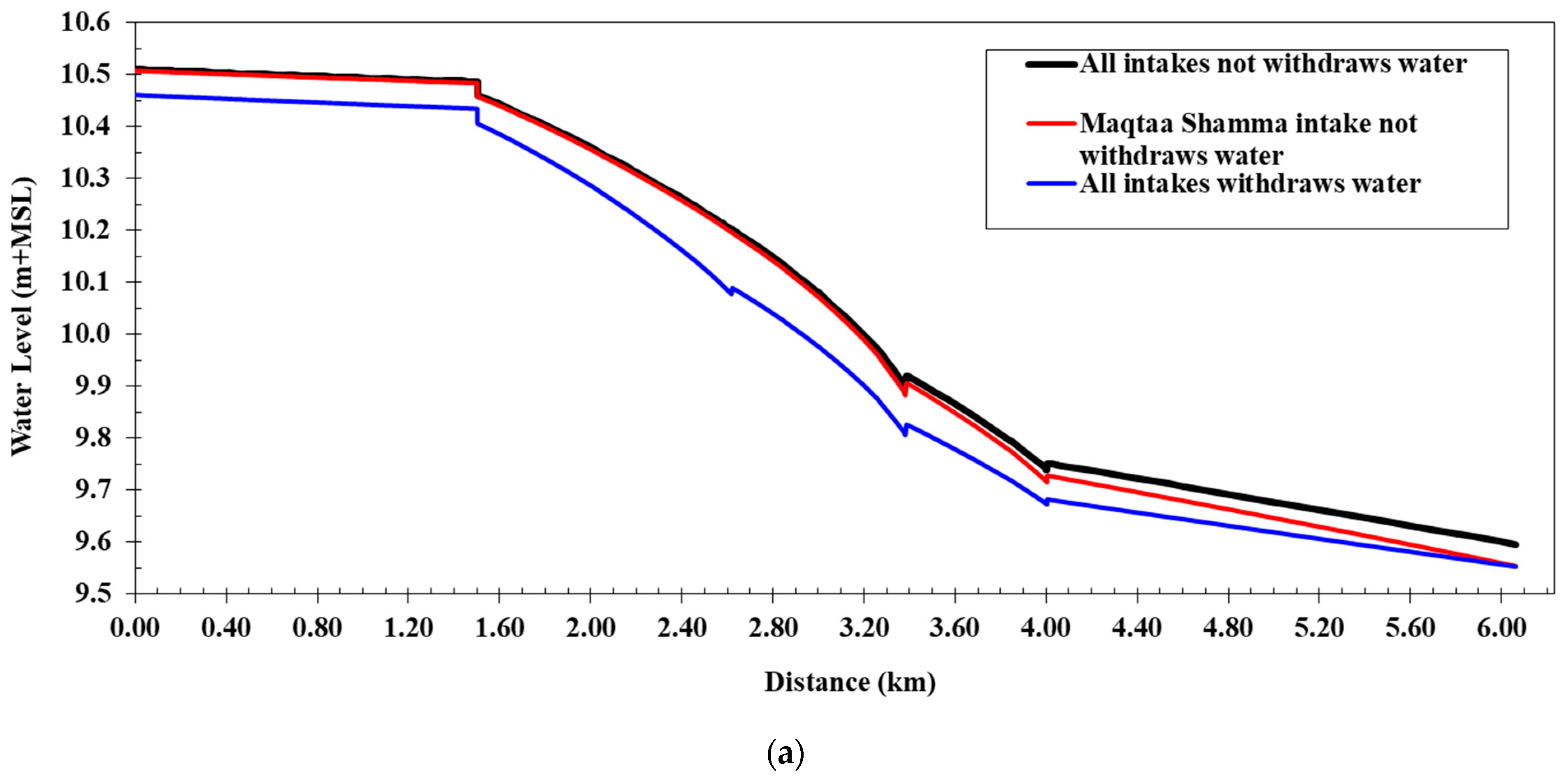
Figure 11a illustrates a comparison of water levels along the Western Meleg Canal after lining and covering the designated stretch for cases a, b, and c.
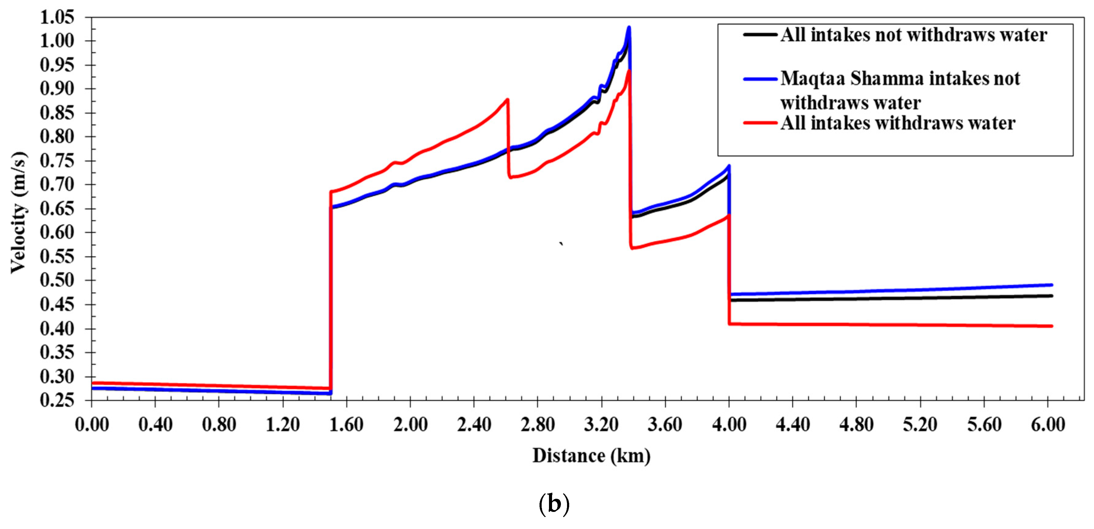
Figure 11b provides a comparative view of water velocities under these operation scenarios.
It can be noticed that when all intakes on the canal were closed, water levels along the canal, as determined by the numerical model, ranged from 10.51 m at the canal’s outset to 9.59 m at the canal’s end. Flow velocities within the canal spanned from 0.26 to 1.00 m/s, and water depths varied from 1.00 m to 1.55 m. The water pressure difference over the covered section (1.500–4.000 km) amounted to 74 cm, with the coverage maintaining free flow. The lowest water levels were observed when all canal intakes were operational, ranging from 10.46 m at the canal’s beginning to 9.54 m at the end. In this scenario, flow velocities ranged from 0.28 to 0.93 m/s, and the water pressure difference over the coverage increased to 76 cm. For the case involving the closure of the Maqtaa Shamma Canal intake and the operation of the Al-Ghouri and Halfaya Canal intakes, water levels ranged from 10.51 m at the canal’s outset to 9.54 m at the canal’s end. Flow velocities within the canal under this scenario ranged from 0.26 to 1.03 m/s, and the pressure difference on the coverage reached 76 cm, with the maximum water velocity occurring at the coverage entrance.
4.5. Scenario Costs
Table 3 shows the difference between the total cost of executing the second scenario of canal lining and the fourth scenario of canal coverage for the distance from 1.500 to 3.400 km, which indicates that the cost of coverage is more than four times the cost of lining.
4.6. Discussion
The hydraulic model of the canal also simulated the reach after lining works, bed width contraction, and covering of the distance from 1.500 km to 3.400 km, for the following three cases: (1) no water withdrawal from the intakes along the canal; (2) closure of the intake of the Maqtaa Shamma Canal at km 2.600 only, while intakes of the Al-Ghouri Canal and Halfaya Canal were turned on; and (3) all intakes along the Western Meleg Canal, including the Maqtaa Shamma Canal, Al-Ghouri Canal, and Halfaya Canal, were turned on. It is clear that the effect of narrowing the bed width of the Western Meleg Canal on the water levels was above the design levels by 2 to 6 cm, and the maximum flow velocity was 0.72 m/s, which is a safe velocity in lined canals. For the covering alternative, the pressure difference through the covering (1.500:4.000 km) is 74 cm, and the covering operates under free flow. The cost of covering is four times greater than the cost of plain concrete lining. New canal designs should be considered by irrigation directories and research centres in Egypt to gain the best hydraulic performance after rehabilitations and to maintain the required water levels.
5. Conclusions
A comprehensive case study was conducted to address the need for improved irrigation system management near the Meleg El Gharbia Canal in Menoufia Governorate, Egypt. This study focused on a specific section of the canal, spanning from 1.500 to 3.400 km, facing challenges related to the proximity of existing buildings along the canal banks, which could not be removed. The presented study utilized a hydraulic model of the Western Meleg Canal, initially considering its maximum discharge as 2.89 m3/s before lining, with a Manning’s roughness coefficient of n = 0.030. The hydraulic model was then used to simulate various scenarios, including the post-lining phase, bed width contraction, and covering of the canal from 1.500 km to 3.400 km, where the bed width was set at 4.00 m. Three distinct cases were examined: (1) no water withdrawal from the intakes along the canal; (2) closure of the intake of the Maqtaa Shamma Canal at km 2.600, while opening intakes of the Al-Ghouri Canal and Halfaya Canal; (3) activation of all intakes along the Western Meleg Canal, including the Maqtaa Shamma Canal, Al-Ghouri Canal, and Halfaya Canal. The study revealed that narrowing the bed width of the Western Meleg Canal had a limited impact on water levels and flow velocities, with water levels remaining within 2 to 6 cm of design levels, and it had a maximum flow velocity of 0.72 m/s, which is considered safe for lined canals. Regarding covering the canal, the pressure difference along the covered stretch (1.500 to 4.000 km) was 74 cm, and the covering operated under free flow conditions. However, it was noted that the cost of covering was significantly higher than plain concrete lining.
The study’s key recommendation was to contract the bed width of the Western Meleg Canal from kilometer 1.500 to kilometer 3.400 to 4.0 m. This change had a limited impact on water levels and velocities but preserved the width of an adjacent road (Shebeen—Berket El-Saba). To mitigate the rise in velocities during lining, the study suggested the importance of adjusting the design sections to maintain water depth. In conclusion, these findings support Egypt’s national project for canal lining and rehabilitation, emphasizing the need for customized canal designs and a focus on hydraulic performance and water level maintenance during rehabilitation efforts. Each canal slated for rehabilitation should undergo an individualized study to determine optimal design dimensions.
