Article

Influence of Blade Exit Angle on the Performance and Internal Flow Pattern of a High-Speed Electric Submersible Pump

1
School of Energy and Control Engineering, Changji University, Changji 831100, China
2
College of Electrical and Mechanical Engineering, Nanchang Institute of Technology, Nanchang 330044, China
3
College of Hydraulic Science and Engineering, Yangzhou University, Yangzhou 225009, China
*
Author to whom correspondence should be addressed.
Water 2023, 15(15), 2774; https://doi.org/10.3390/w15152774
Submission received: 29 June 2023 / Accepted: 28 July 2023 / Published: 31 July 2023
(This article belongs to the Special Issue Design and Optimization of Fluid Machinery)

Abstract

:
The impeller vane exit placement angle has a critical role in the flow characteristics of the fluid inside the lobe, thus having a profound effect on the overall pump performance. The purpose of this study is to investigate the effect of the impeller exit angle on the operating characteristics of a high-speed well submersible pump, and the numerical calculation results of the original model are in good agreement with the experimental results. In this paper, five different impeller vane exit angles, namely 10°, 15°, 20°, 25° and 30°, are selected for numerical analysis based on the original model, and the flow conditions of 0.6 Q, 1.0 Q and 1.4 Q are analyzed for each angle. The results show that the impeller vane exit placement angle not only affects the static pressure distribution, velocity distribution and streamline distribution within the impeller and guide vane, but also has a significant effect on the head curve, power curve and efficiency curve of the well submersible pump. As the flow slip inside the impeller of high-speed well submersible pumps intensifies, the large impeller outlet angle will cause the power of the impeller to increase linearly with the flow rate, thus reducing the pump efficiency. In the low-flow and high-flow conditions, a small outlet angle of 10° will make the efficiency of high-speed submersible pumps higher than in other conditions, and these findings can provide some reference for the optimal design of high-speed submersible pumps.

1. Introduction

With the rapid development of agricultural modernization, well submersible pumps are widely used in farm irrigation and sprinkler irrigation [1]. According to the data given by the construction of water conservancy projects in 2022, the effective irrigated area of farmland in China is 1.037 billion mu, accounting for 54% of the arable land area. Groundwater used for irrigation is a valuable underground resource with high development value. In addition, well submersible pumps are also widely used in oil production and geothermal utilization [2]. As well, submersible pumps are the core equipment for pumping low-level fluids [3], and so the market has also placed higher demands on their performance in recent years [4,5,6]. Due to the superiority of well submersible pumps in pumping underground fluids, more and more scholars have conducted research on well pumps [7]. With the help of theoretical analysis, numerical simulation and experimental measurement, much detailed and in-depth research has been conducted for the optimal design of impeller and guide vane parameters of well submersible pumps [8], which has enriched the theoretical basis of well submersible pump design and made a useful exploration in improving the design method of submersible pumps and improving the hydraulic performance of pumps.
The selection of the impeller outlet placement angle of the submersible pump is closely related to the internal flow field distribution of the diffuser [9], which becomes the key to the performance of the well submersible pump. The impeller vane outlet placement angle will directly affect the hydraulic efficiency of the whole pump, and how to set the impeller vane outlet placement angle has become a key issue of concern to enterprises and scholars, and is also the main focus of this research paper. Therefore, this paper will take different impeller vane outlet angles as the research scenario for supplementary research, focusing on the analysis and study of how the pump performs under different impeller vane outlet angles, in order to explore the influence of the impeller vane outlet angle on the overall efficiency of well submersible pumps, and put forward countermeasure suggestions to provide the basis for more in-depth research.
For the selection of impeller inlet and outlet parameters of submersible pumps, a large number of scholars at home and abroad have carried out relevant research. There has been much research, mainly from the analysis of diffuser structure parameter changes and air inlet structure perspective, based on setting different parameters of the import and export scenario theoretical approach, with scholars carrying out qualitative research on the import and export diffuser structure parameter changes. It is confirmed that the angle of the diffuser and the angle of the vane inlet have a great influence on the efficiency and head of the well submersible pump. The following areas are specifically included. Neverov et al. [10] focused on the selection and analysis of impeller inlet and outlet parameters of pumps by analyzing the experimental results of impeller inlet and outlet parameters, and found that the hydraulic performance of submersible pumps is influenced by the impeller inlet and outlet parameters. Siddique et al.’s [11] CFD method was used to study the centrifugal pump by changing the impeller inlet and outlet angles in the shape of the impeller radial surface, and it was found that the input power can be reduced and the head of the centrifugal pump can be increased by changing the impeller inlet and outlet angles. Firatoglu et al. [12] studied the effects of the number of stages, impeller outlet width and vane outlet placement angle on the performance of well submersible pumps. They investigated these using a combination of CFD and experimental methods, and it was found that the impeller vane outlet placement angle had a significant effect on the pump performance. Arocena et al. [13] conducted a numerical study of the performance of submersible pumps. The prediction of backflow, vortex formation and cyclonic flow caused by off-design conditions was investigated using CFD simulations to verify the pump head, efficiency, flow rate and other characteristics derived in different inlet structure designs. The performance degradation of TDH predicts a change in both the hydraulic phenomena and the characteristic curve of the pump. Qingshun et al. [14] modeled and simulated five different guide vane blade inlet angles, and the results show that the guide vane blade inlet angle has a large effect on efficiency and maximum flow rate.
Based on the above analysis, scholars have conducted simulation and experimental research based on different techniques to improve the overall performance of submersible pumps by improving their key components [15,16,17], but the research on the influence of the impeller outlet angle of well submersible pumps on the pump performance is not detailed enough. Therefore, this paper selects different impeller vane outlet angles to analyze their effects on the performance of well submersible pumps, in order to provide some reference for the optimal design of well submersible pumps. This paper is aimed at researching the impact of the well submersible pump impeller vane outlet angle on pump performance and other issues of research that have a certain theoretical significance and practical significance. This paper will conduct an in-depth analysis of well submersible pumps, and the results will expand the scope of research on well submersible pumps and enrich the research on the influencing factors of well submersible pump performance. The results of the study will help the government and enterprises to gain a deeper understanding of the factors affecting the performance of well submersible pumps, and will propose solutions to the problem of loss of performance of well submersible pumps to help the current studies of well submersible pumps and to help develop strategies to manage the problem.

2. Numerical Simulation Methods

2.1. Computational Models

In this paper, a centrifugal pump with a speed n = 6000 r/min was selected to study the effect on pump performance, and the main design parameters of this centrifugal pump are shown in Table 1.
The commercial 3D software UG12.0 [18] was used to model all calculation domains in the numerical calculation. And in order to consider the influence of the leakage of the mouth ring gap on the pump performance, the full-flow field numerical calculation is used, as shown in Figure 1. The calculation domain includes the inlet section, impeller, pump chamber, diffuser, outlet section, where the gap portion of the oral ring includes two parts, and the anterior and posterior chambers. In order for the flow to develop more fully, the length of the inlet and outlet sections of the calculation domain are extended by four times the diameter of the inlet and outlet pipes, respectively.

2.2. Grid Division

In this paper, the commercial software ANSYS-ICEM is used for meshing each computational domain. Because this article mainly studies the influence of single-factor changes in structural parameters in the impeller on pump performance and internal flow field, we adopt structured grids for the impeller part and encrypt the leading and trailing edge parts of the blade. The overall computational domain grid is shown in Figure 2, where the number of grid cells is 541,482, the grid type is a hexahedral mesh and the number of nodes is 93,469.The efficiency, head and power are used as indicators for the grid irrelevance test, the global grid size is used to control the grid density, and the grid quality of the calculation domain is ensured by refinement of the local style, as can be seen from Table 2. Considering the calculation time and calculation accuracy, the global grid size of 1 mm is used for the numerical calculation.

2.3. Calculation Scheme and Boundary Conditions

Numerical calculations were performed using ANSYS-CFX 17.0 software (Pittsburgh, PA, USA). The standard k-ε turbulence model is used for the turbulence model. The computational impeller domain is set to the rotational domain, and all other computational domains are set to the stationary domain. The frozen rotor method is used for data transfer to the intersection between the stationary and rotational domains. In order to consider the influence of the impeller cover on the flow, the other inner wall surfaces in the pump chamber, excluding the contact with the impeller outlet surface, are set as rotating wall surfaces. A roughness of 10 μm is set for each calculation domain surface to take into account the influence of the material on the internal flow characteristics of the pump. The boundary conditions are set to pressure inlet and mass outflow. The reference pressure is set to a standard atmospheric pressure, and the residual convergence accuracy is set to 10−4, with a no-slip boundary condition and standard wall surface function for convergence accuracy. The schematic diagram of the import and export boundary conditions is shown in Figure 3.

2.4. Identification of Test Factors

This paper focuses on the effect of the impeller blade outlet placement angle on the pump performance. The impeller blade exit angle is the blade leaf-type exit side tangent line and the impeller outer edge of the same point made by the tangent line angle, as shown in Figure 4. The blade exit placement angles set in this paper are 10°, 15°, 20°, 25° and 30°, and the three flow conditions of 0.6 Q, 1.0 Q and 1.4 Q are used to study the effect of different vane outlet angles on the performance of submersible pumps.

3. Analysis of Numerical Simulation Results

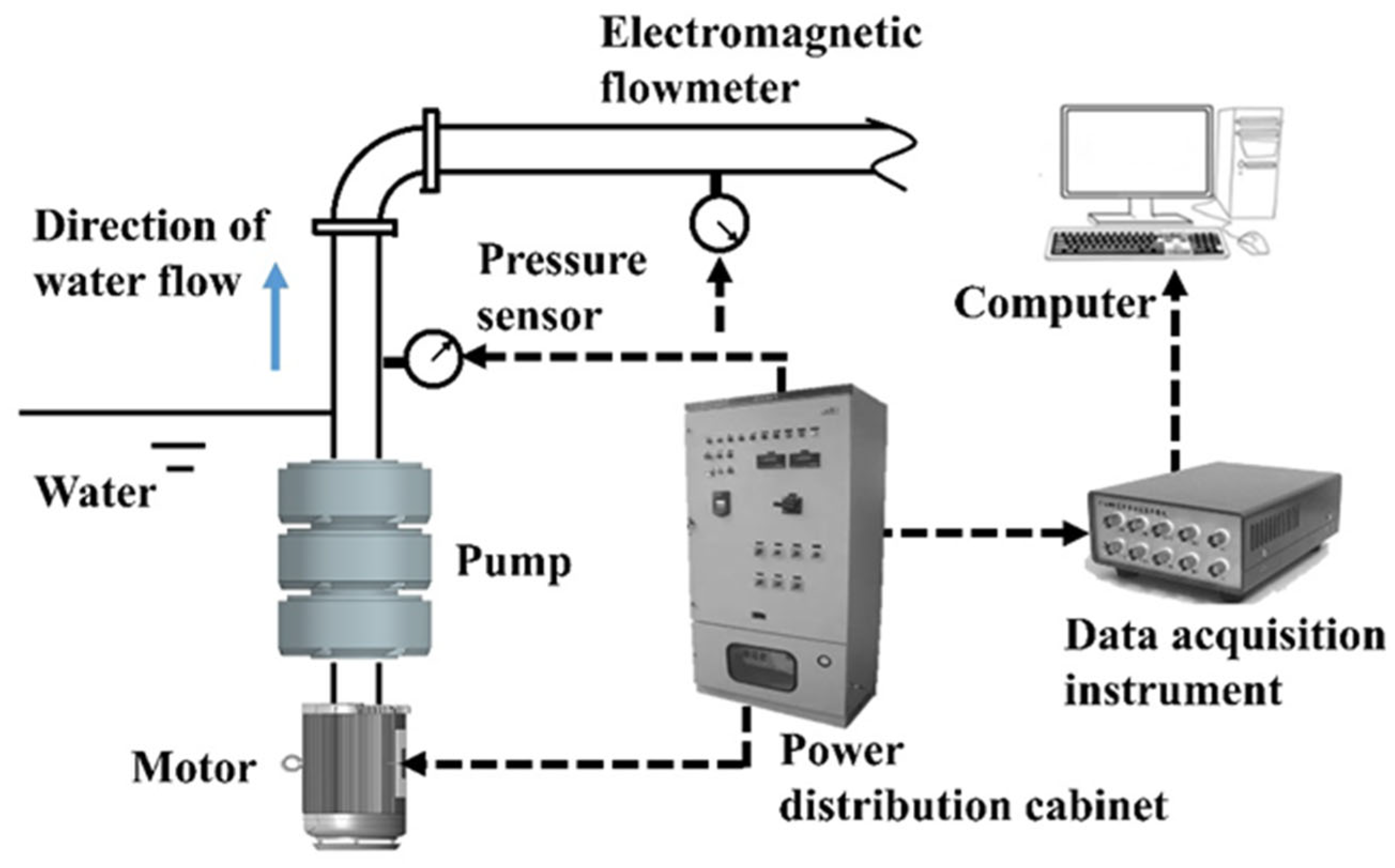
3.1. Experimental Verification

3.1.1. Practical Experimental Control

In order to verify the correctness of the numerical simulation method used, the original model was tested experimentally using a turbine flowmeter DN100 type, with 0.5 accuracy, to collect the flow points of the medium-ratio submersible well pump. The schematic diagram of the two-dimensional setup of the experimental bench is shown in Figure 5. During the test, the pump inlet line valve was kept fully open, and the flow condition points were collected through the turbine flow meter on the outlet line. Table 3 shows the results of the pump performance tests. Since the actual speed of the pump during the test was 6000 r/min, the pump outlet pressure was much higher than the inlet pressure, and the inlet pressure was set to 0 Kpa during the test because the pressure gauge range was larger and the negative inlet pressure was smaller.
A comparison of the experimental performance of the pump and the calculated performance of the numerical simulation is shown in Figure 6. In order to reflect the external characteristic change curve from the shut-off point to the maximum flow condition during the pump test completely, five flow condition points are taken in the numerical calculation, namely 0.6 Q, 0.8 Q, 1.0 Q, 1.2 Q and 1.4 Q. The comparison shows that the results of the numerical simulation experiment and the actual operation experiment have approximately the same curve changes in the whole operating condition range of the pump, and accurately predict the trend of the pump’s external characteristics curve. This shows that the method of the numerical simulation experiment adopted in this paper is feasible and has practical research significance. This further ensures the accuracy of the design solution to study the effect of the impeller blade outlet placement angle on pump performance by numerical simulation.
Also, the pump used in this paper is a three-stage centrifugal pump, because the primary impeller of a three-stage centrifugal pump is more affected by the initial conditions of different fluid flows and pressures. The three-stage impeller is affected by the first two stages of the impeller and the outlet over-flow fluid, which, like the first-stage impeller, does not restore the smooth flow field in the pump well. Therefore, in this paper, the secondary impeller is selected for the impeller internal flow field analysis.

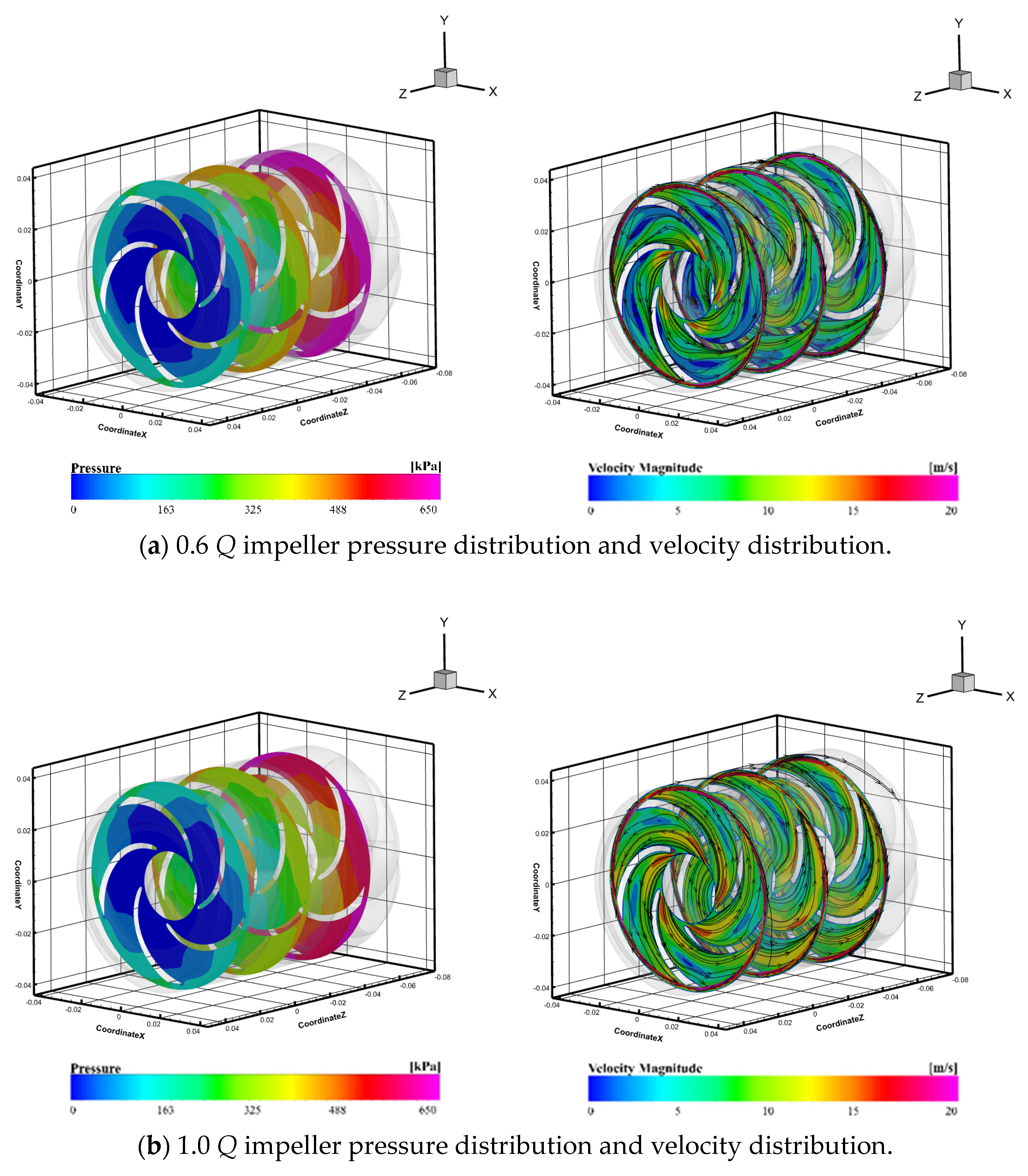
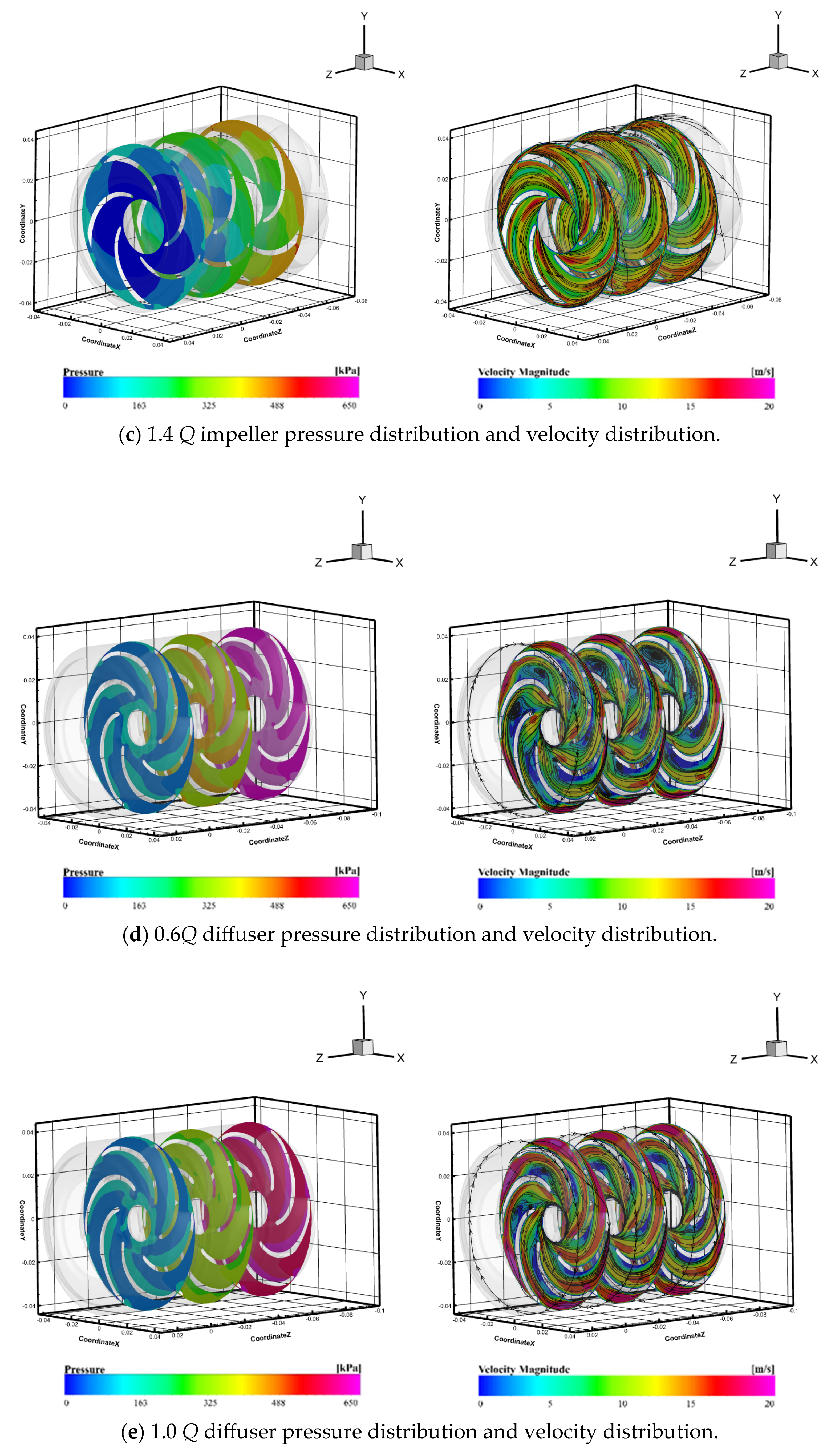
3.1.2. Initial Model Impeller and Diffuser Flow Field Distribution under Different Flow Conditions

It is clear from Figure 7a–c that the working surface of the blade is more evenly distributed in terms of pressure and velocity flow line compared with the back of the blade. This is because, when entering the impeller internal flow field, the more fitted the impeller blade exit placement angle of the fluid into the flow rate is, the closer it will be to the blade work surface flow, leading to the formation of a relatively stable laminar flow environment. However, in the back of the blade, due to the faster loss of fluid, the blade attachment state will be formed after the blade is not connected with each other separation area, and these areas of the flow rate and pressure are different from the design value of the impeller, as the original has been maintained in the blade above the high-pressure fluid flowing into a low-pressure, slow-speed area, thus producing the corresponding energy loss that is the separation loss. The separation loss is closely related to the impeller blade exit angle setting, and, after adjusting, the impeller blade exit angle constantly adapts to the actual working conditions to obtain a more stable impeller internal flow field.
Similarly, in the diffuser section, the analysis in Figure 7d–f shows that, in the outlet of the diffuser, because the liquid has just obtained a large amount of kinetic energy from the rotation of the impeller, in contact with the stationary diffuser, the instantaneous velocity change is large, so a large pressure is generated in the diffuser internal flow field, but the velocity distribution value is small and the flow line can be seen to produce a large turbulence area and a higher vortex position. This paper analyzes this phenomenon based on the relevant design basis of the pump, and finds that the inlet section of the diffuser is influenced by the impeller blade exit angle, and the diffuser inlet angle of the impeller blade exit angle can make the fluid flow out of the impeller into the internal flow field of the diffuser to reduce the velocity loss significantly, so that the pressure and velocity distributions of the internal flow field of the diffuser are smooth and even. In summary, this paper found that the impeller and diffuser internal flow fields, and even affect the performance of the entire pump, are very important factors, as is the impeller blade exit angle, as, if the exit angle is set too small, it will be difficult for the fluid to obtain the kinetic energy provided by the impeller, and, if the exit angle is set too large, the fluid will face a faster diffusion rate when entering the impeller internal flow field, resulting in large separation losses. And, an unreasonable impeller vane outlet placement angle will affect the liquid flowing into the diffuser and the inlet velocity, resulting in turbulence in the internal flow field of the diffuser, a vortex phenomenon, and increased energy loss, which will reduce the efficiency of the pump.
Therefore, in this paper, the analysis of the flow field inside the impeller is carried out by changing the angle of the impeller blade exit angle, which has a direct influence on the flow field, under the premise of controlling the above variables in unison. Determining a stable and uniform, non-rotating, non-turbulent vortex flow field inside the impeller that best suits the actual ideal state will ensure stable and efficient operation of the impeller and, ultimately, will improve the overall efficiency of the centrifugal pump.

4. Analysis and Discussion

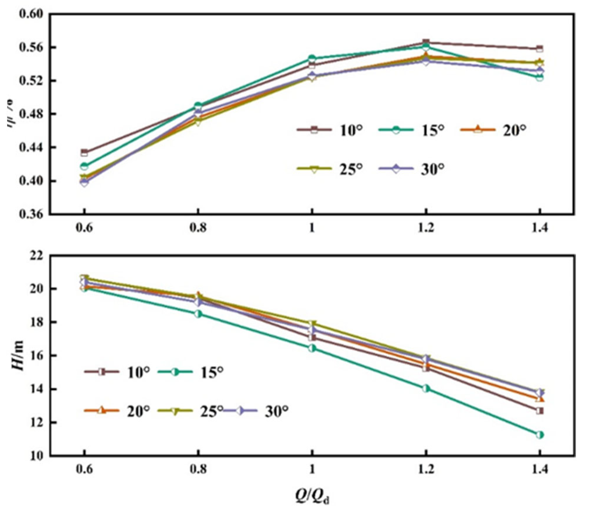
4.1. Effect of Different Blade Exit Placement Angles on External Characteristic Curves

Figure 8 shows the effect of different blade placement angles on the external characteristic curves of head and efficiency. From the figure can be seen that, in the small flow conditions, the smaller the blade outlet angle is, the higher the head is, and, in the large flow conditions, the larger the blade outlet angle is, the higher the head is. It can also be found from the graph that, when the vane placement angle is 25°, the well submersible pump has a high head in a wide range.
It can be seen from Figure 8 that, when the impeller outlet angle is small, the efficiency is higher in the entire flow range. Analysis of the reason shows that this is mainly due to the well submersible pump and to the limitations of the well diameter: the inner pump casing is generally cylindrical, and, when the impeller speed is high, the impeller outlet water flow will have a large slip angle. That is, the actual impeller outflow angle will be less than the blade outlet resting angle, resulting in the blade outlet resting angle being larger when the relative slip is more serious.
Figure 9 shows the effect of different blade placement angles on the power external characteristic curves. From the figure it can be seen that the effect of the blade exit placement angle on the power is greater with the 20°, 25° and 30° impeller exit placement angles of power than 10° and 15°, where the impeller blade exit placement angle is higher. The main reason is that the impeller vane outlet placement angle is set relatively large, to a certain extent to increase the pump outlet flow. At this time, in order to provide a corresponding energy supply to overcome the greater resistance to fluid flow, it is necessary to provide greater power to the pump. From the figure it can also be seen, when the blade exit angle is small and the flow rate increases, the power will appear to first increase and then reduce the phenomenon. Analysis of the reason shows that this is mainly due to the blade placement angle being small, which will cause the turbulent flow of water and vortex generation, and the formation of the backflow phenomenon inside the pump body, resulting in the impeller consumption power increase.
Table 4 shows the comparison of head, efficiency and power of the well submersible pump when the vane placement angles are 10° and 25°, respectively, and from Table 4 it can be seen that the small vane outlet placement angle can affect single-stage power and improve the efficiency of high-speed pumps. Therefore, our work will provide some reference for researchers to study the optimal design related to high-speed submersible pumps.

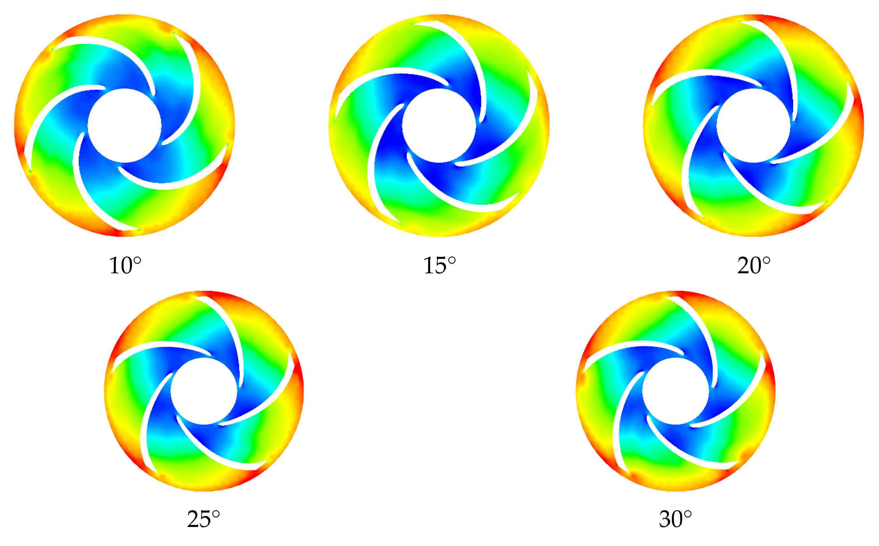
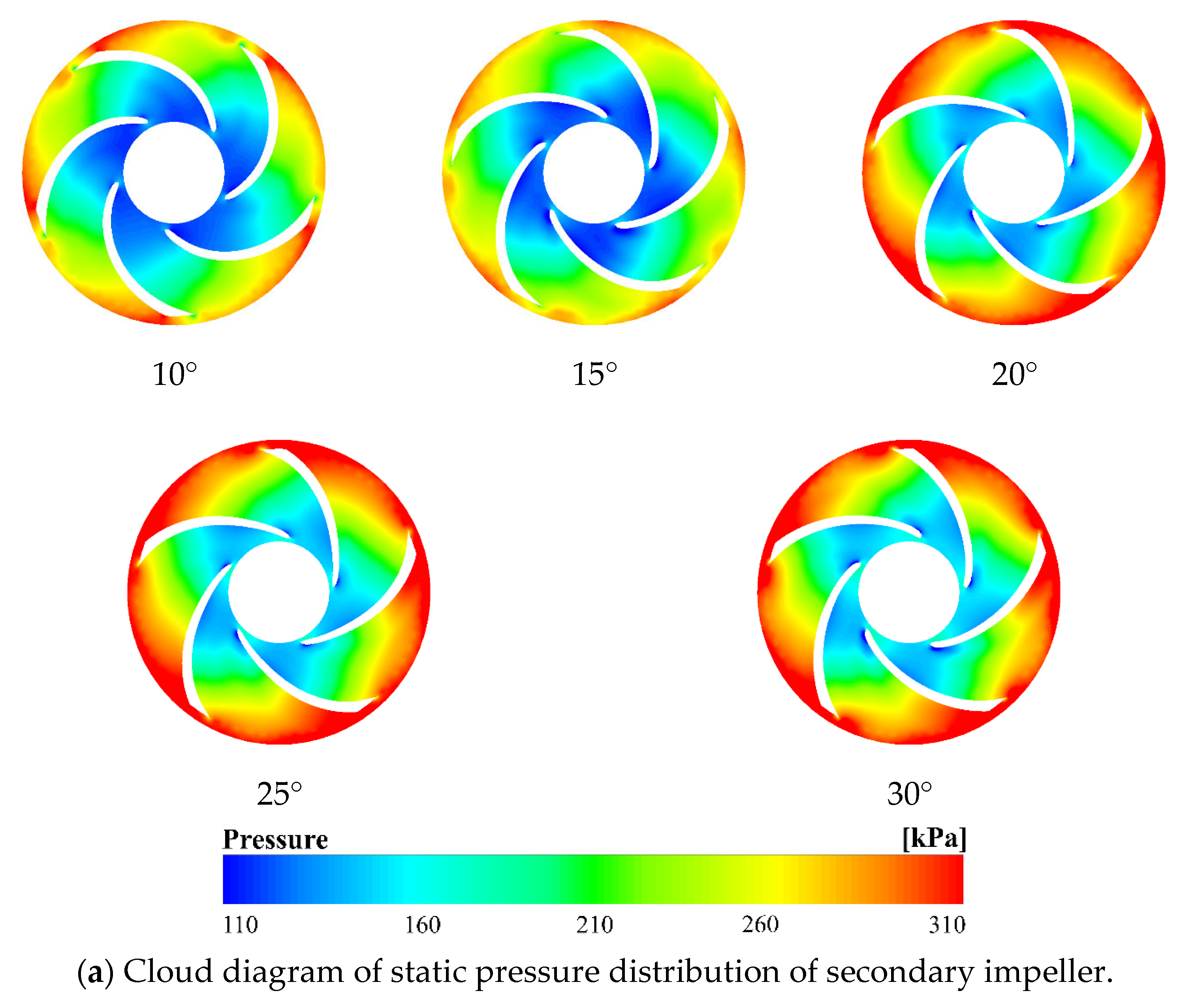
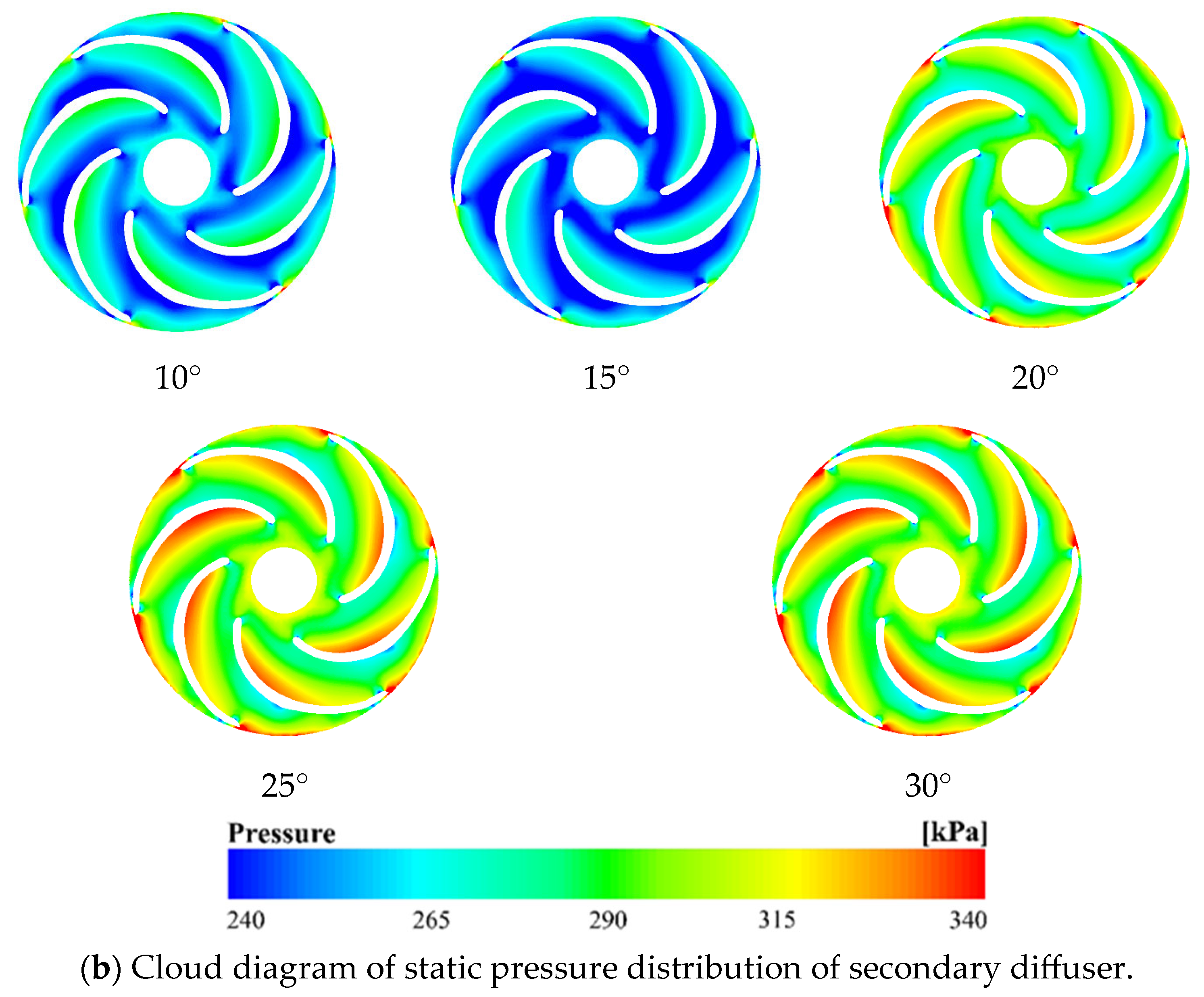
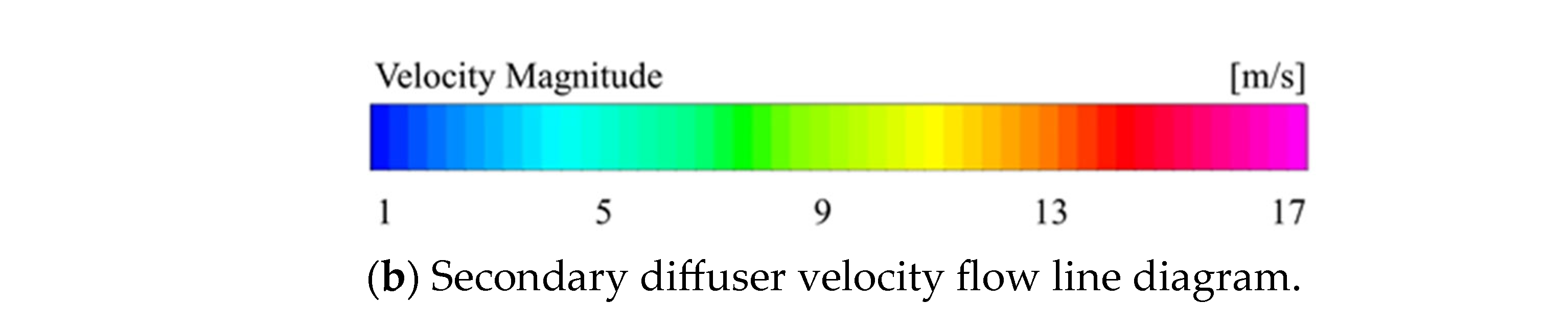
4.2. Internal Flow Field Analysis

Figure 10, Figure 11 and Figure 12 show the static pressure distribution clouds at the second-stage impeller cross section under 0.6 Q, 1.0 Q and 1.4 Q operating conditions, respectively. All show a gradual increase in pressure along the radial direction of the impeller to the outside. In other words: the impeller has a low pressure in the inlet area and a high pressure in the outlet area. It can be seen from Figure 11 that the impeller static pressure gradient increases and then decreases with the increase of impeller blade outlet placement angle under the 0.6 Q working condition. The 1.0 Q flow condition and the 1.4 Q high-flow condition in Figure 12a show the same trend as the low-flow condition in Figure 13, and the magnitude of the change is more obvious. Accordingly, it can be seen that the impeller blade outlet placement angle has a certain influence on the pressure distribution of the internal flow field of the impeller. Under the small-flow condition of 0.6 Q, it can be seen by the comparison between the working surface of the blade and the back of the blade that, when the blade exit angle is set to 10°, the distribution of the impeller internal flow field static pressure distribution cloud is more uniform, and, under the 1.0 Q flow condition, it can be seen in the Figure 12a graph that the internal flow field pressure distribution is more even when the blade exit angle is 25°. However, under high-flow conditions, when the impeller blade outlet placement angle is set to a large angle of 20° or more, the high-pressure area of the impeller internal flow field is widely distributed, the low-pressure area generated in the inlet area is smaller, and the pressure distribution of the impeller internal flow field is smoother. This paper has found that this is because, when the flow conditions are small, the impeller’s blade exit speed is low, and the rotation speed of the impeller center is also low. Therefore, the outlet placement angle should be set smaller to avoid problems such as reduction of the impeller flow coefficient and impeller stall speed. When the flow conditions become larger, there is a need to adjust the impeller blade outlet placement angle, in order to increase the impeller outlet channel area, to ensure that the flow channel has sufficient through capacity to avoid the flow being too large, resulting in flow-channel blockage or flow instability.
On the other hand, it is evident from the guide lobe portion of Figure 10b, Figure 11b and Figure 12b that a very obvious low-pressure area forms in the inlet area of the diffuser, which is due to the fluid in the impeller, after the acceleration into the diffuser, being restricted by the inlet geometry inside the diffuser, so that the fluid in contact with the diffuser of the instant flow is met with a certain resistance, and then produces a pressure drop. This is not conducive to the smooth distribution of pressure in the flow field inside the diffuser. The impeller outlet placement angle will have an important influence on the pressure distribution inside the diffuser. The pressure distribution on the diffuser shows a general trend of gradually increasing from the inlet to the outlet, reaching the highest at the diffuser outlet. Different blade outlet placement angles will change the low-pressure area of the diffuser inlet area, and from Figure 12 it can be seen that, with the increase of the placement angle, the low-pressure area of the diffuser inlet position gradually reduces, causing the internal hydraulic loss of the diffuser to reduce. At the same time, by comparing the static pressure clouds of the diffuser under different flow conditions under 0.6 Q, 1.0 Q and 1.4 Q, it can be found that, the smaller the impeller outlet placement angle is, the more serious the influence on the static pressure clouds of the diffuser under high-flow conditions is. It can be seen from Figure 13 that, when the impeller’s outlet resting angles are 10° and 15°, a more serious low-pressure area is generated inside the diffuser. A serious hydraulic loss is generated, which is the reason for the sudden increase in power in Figure 9 under low-flow conditions when the outlet resting angle is 10°.
The velocity and streamline distributions at the second-stage impeller cross section under 0.6 Q, 1.0 Q and 1.4 Q operating conditions are shown in Figure 13a, Figure 14a and Figure 15a, respectively. As can be seen from the diagram in Figure 14, when the blade outlet placement angle is 10°, more obvious low-speed zones are seen in the impeller inlet leading edge and impeller outlet position, and there is secondary flow from the flow line distribution, which can be found in the low-speed zone, and these problems may lead to impeller vibration. As the blade placement angle increases, the low-speed zone inside the runner will shift from the back area of the blade to the working surface area of the blade, and it can also be found that the location of the low-speed zone will move from the outlet position to the inlet position. And it can be found that, with the increase of the blade exit placement angle, the low-speed region inside the impeller runner will be further reduced. Analysis of the secondary impeller velocity streamline distribution clouds in Figure 14 and Figure 15 shows that, with the change of the blade exit placement angle, there will be obvious changes in the impeller runner, while the increase of the exit placement angle can make the velocity cloud distribution at the impeller exit position more uniform.
The velocity and streamline distribution at the cross section of the second-stage diffuser under 0.6 Q, 1.0 Q and 1.4 Q operating conditions are shown in Figure 13a, Figure 14a and Figure 15a, respectively. As can be seen from Figure 14b, the effect of different blade exit placement angles on the internal flow field of the diffuser is relatively large. Specifically, under small-flow conditions, when the blade placement angle is 10°, the internal velocity field of the diffuser has an obvious low-pressure area, and the internal low-speed area of the diffuser is close to the position of the working surface of the diffuser. At the same time, it can be found that the velocity gradient is larger in the diffuser exit area, and with the increase of the impeller blade exit placement angle. It can be found that the velocity gradient in the region of the inlet position of the diffuser matching the impeller increases significantly, and analysis of the reason shows that this is mainly due to the fact that the inner casing of the well submersible pump is cylindrical, in the impeller outlet position there is an obvious slippage phenomenon, and that when the impeller outlet placement angle is large this will produce a large impact loss. With the increase in traffic, further analysis of Figure 14b and Figure 15b reveals that, as the flow rate increases, the low-speed zone inside the diffuser will gradually decrease, and the velocity distribution inside the diffuser will be more uniform. The same can be found when the impeller blade exit angle increases: and the impeller matching diffuser inlet area velocity gradient will also increase, and the loss increases. This is consistent with the conclusion of the data from the external characteristic curve in Figure 9, resulting in a monotonic linear increase in power with flow for larger angles of placement, while a smaller angle of placement will appear as the flow changes with the power, and the power will essentially tend to level off.

5. Conclusions

In this study, a combined approach of numerical simulation and experimental analysis was employed to investigate the external characteristic curves and internal flow fields of multi-stage well submersible pumps by varying the outlet angle of five groups of impellers under corresponding boundary conditions. Through rigorous analysis, the following conclusions have been derived.
The numerical simulation results presented in this paper demonstrate that the selected impeller blade outlet angles of 10°, 15°, 20°, 25° and 30° exert a notable influence on the hydraulic performance of centrifugal pumps. Examining the head-flow curve reveals that smaller blade outlet angles result in higher head values under low-flow conditions, while larger outlet angles lead to increased head values under high-flow conditions. Analyzing the power-flow curve reveals a saturation power phenomenon with smaller impeller blade outlet angles, whereas larger angles exhibit a monotonically increasing trend with increasing flow rates. Moreover, examining the efficiency-flow curve for high-speed well submersible pumps indicates that smaller impeller blade outlet angles yield higher pump efficiency. Compared with a blade exit angle of 25°, using a small blade exit angle of 10° will result in an increase of 7.4%, 2.6% and 3.1% for small-flow case 0.6 Q, rated-flow case 1.0 Q and high-flow case 1.4 Q, respectively.
Analyzing the static pressure distribution within the impeller reveals that the impeller blade outlet angle significantly affects the internal static pressure distribution. As the outlet angle increases, the impeller’s static pressure gradient initially rises and then declines. Notably, under high-flow conditions, the impeller’s internal flow field exhibits a wider distribution of high-pressure areas and a smaller generation of low-pressure areas in the inlet region, resulting in a smoother pressure distribution throughout the impeller. Consequently, large impeller outlet angles are recommended for high-flow pumps to ensure optimal outflow performance.
Examining the velocity flow field distribution within the impeller, it becomes evident that the impeller blade outlet angle notably impacts the distribution of velocity flow lines, particularly in the diffuser’s inlet area, where the velocity gradient is significantly influenced. Increasing the impeller blade outlet angle leads to a higher velocity gradient in the diffuser’s inlet area, further exacerbating diffuser losses.
In conclusion, this study provides comprehensive insights into the influence of impeller blade outlet angles on the performance characteristics of well submersible pumps. The findings highlight the importance of selecting appropriate outlet angles to optimize hydraulic performance, efficiency and pressure distribution within the impeller. These results contribute to the design and operation of well submersible pumps, enabling engineers to make informed decisions for achieving superior performance and efficiency in various applications. Further research can build upon these findings to explore additional factors impacting pump performance and refine design strategies for enhanced operational outcomes.

Author Contributions

Conceptualization, C.H. and Y.Y.; methodology, X.C.; software, J.L.; validation, Y.Y. and J.L.; formal analysis, C.H.; data curation, X.C.; writing—original draft preparation, C.H.; writing—review and editing, Y.Y.; supervision, Y.Y. All authors have read and agreed to the published version of the manuscript.

Funding

This work was supported by the Natural Science Foundation of Xinjiang (Grant No. 2021D01C008); Natural Science Foundation of Jiangsu Province (Grant No. BK20220587); Cooperative research project of the Ministry of Education’s “Chunhui Program” (Grant No. HZKY20220117); China Postdoctoral Science Foundation: (Grant No. 2023M732979).

Data Availability Statement

Not applicable.

Conflicts of Interest

The authors declare no conflict of interest.

References

  1. Bai, L.; Zhou, L.; Han, C.; Zhou, Y.; Shi, W. Numerical study of pressure fluctuation and unsteady flow in a centrifugal pump. Processes 2019, 7, 354. [Google Scholar] [CrossRef] [Green Version]
  2. Petrochenkov, A.; Ilyushin, P.; Mishurinskikh, S.; Kozolov, A. Development of a Method for Improving the Energy Efficiency of Oil Production with an Electrical Submersible Pump. Inventions 2023, 8, 29. [Google Scholar] [CrossRef]
  3. Yang, Y.; Zhou, L.; Hang, J.; Du, D.; Shi, W.; He, Z. Energy characteristics and optimal design of diffuser meridian in an electrical submersible pump. Renew. Energy 2021, 167, 718–727. [Google Scholar] [CrossRef]
  4. Shi, W.D.; Lu, W.G.; Wang, H.L.; Li, Q.F. Research on the theory and design methods of the new type submersible pump for deep well. In Proceedings of the Fluids Engineering Division Summer Meeting, Vail, CO, USA, 2–6 August 2009; Volume 43727, pp. 91–97. [Google Scholar]
  5. Bai, L.; Yang, Y.; Zhou, L.; Li, Y.; Xiao, Y.; Shi, W. Optimal design and performance improvement of an electric submersible pump impeller based on Taguchi approach. Energy 2022, 252, 124032. [Google Scholar] [CrossRef]
  6. Aydin, H.; Merey, S. Design of Electrical Submersible Pump system in geothermal wells: A case study from West Anatolia, Turkey. Energy 2021, 230, 120891. [Google Scholar] [CrossRef]
  7. Zhu, J.; Banjar, H.; Xia, Z.; Zhang, H.-Q. CFD simulation and experimental study of oil viscosity effect on multi-stage electrical submersible pump (ESP) performance. J. Pet. Sci. Eng. 2016, 146, 735–745. [Google Scholar] [CrossRef]
  8. Fengwu, Z. Electric submersible Pump lifting process optimization. In Proceedings of the 2013 2nd International Conference on Measurement, Information and Control, Harbin, China, 16–18 August 2013; Volume 2, pp. 1328–1331. [Google Scholar]
  9. Li, J.; Tang, L.; Zhang, Y. The influence of blade angle on the performance of plastic centrifugal pump. Adv. Mater. Sci. Eng. 2020, 2020, 1–20. [Google Scholar] [CrossRef]
  10. Neverov, V.V.; Kozhukhov, Y.V.; Yablokov, A.M.; Lebedev, A.A. Optimization of a centrifugal compressor impeller using CFD: The choice of simulation model parameters. IOP Conf. Ser. Mater. Sci. Eng. 2017, 232, 012037. [Google Scholar] [CrossRef]
  11. Siddique, M.H.; Mrinal, K.R.; Samad, A. Optimization of a centrifugal pump impeller by controlling blade profile parameters. In Turbo Expo: Power for Land, Sea, and Air; American Society of Mechanical Engineers: New York, NY, USA, 2016; Volume 49712, p. V02CT45A009. [Google Scholar]
  12. Firatoglu, Z.A.; Alihanoglu, M.N. Investigation of the effect of the stages Number, the impeller outlet width, and the impeller outlet angle on the performance of an industrial electric submersible pump. J. Fluids Eng. 2022, 144, 081203. [Google Scholar] [CrossRef]
  13. Arocena, V.M.; Abuan, B.E.; Reyes, J.G.T.; Rodgers, P.L.; Danao, L.A.M. Numerical Investigation of the Performance of a Submersible Pump: Prediction of Recirculation, Vortex Formation, and Swirl Resulting from Off-Design Operating Conditions. Energies 2021, 14, 5082. [Google Scholar] [CrossRef]
  14. Qingshun, W.; Xihuan, S.; Shamseldin, A.Y.; Chaoqun, L. Impacts of blade inlet angle of diffuser on the performance of a submersible pump. Proc. Inst. Mech. Eng. Part E J. Process Mech. Eng. 2020, 234, 613–623. [Google Scholar] [CrossRef]
  15. Yuanyi, L.; Yongyan, L.; Ruiguang, L. The Effect of the Clearance Value of Impeller and Draft-tube for the Performance of Stamping Multistage Centrifugal Pumps. In Proceedings of the 2009 International Conference on Computer and Communications Security, Hong Kong, 5–6 December 2009; pp. 142–145. [Google Scholar]
  16. Shuiguang, T.; Hang, Z.; Huiqin, L.; Yue, Y.; Jinfu, L.; Feiyun, C. Multi-objective optimization of multistage centrifugal pump based on surrogate model. J. Fluids Eng. 2020, 142, 011101. [Google Scholar] [CrossRef]
  17. Zhu, J.; Zhu, H.; Zhang, J.; Zhang, H.-Q. A numerical study on flow patterns inside an electrical submersible pump (ESP) and comparison with visualization experiments. J. Pet. Sci. Eng. 2019, 173, 339–350. [Google Scholar] [CrossRef]
  18. Yu, E.S.; Myoung, B.; Mun, D.; Lee, J.; Lee, J.Y.; Kil, W. Development of an UG NX-based Plug-in Type System for the Simplification of 3D CAD Assembly Models. Trans. Korean Soc. Mech. Eng. A 2017, 41, 1239–1246. [Google Scholar]
Figure 1. Schematic diagram of the full-flow field water domain 3D model of the well submersible pump.
Water 15 02774 g001
Figure 2. Schematic diagram of the main computational domain grid model.
Water 15 02774 g002
Figure 3. Boundary condition model diagram.
Water 15 02774 g003
Figure 4. Impeller blade profile and blade exit placement angle schematic.
Water 15 02774 g004
Figure 5. Schematic diagram of the pump test bench setup.
Water 15 02774 g005
Figure 6. Comparison of the initial model numerical simulation and experimental external characteristic curve of the well submersible pump.
Water 15 02774 g006
Figure 7. Distribution of the flow field in the impeller and diffuser of the original model of the centrifugal pump under different flow conditions.
Water 15 02774 g007aWater 15 02774 g007bWater 15 02774 g007c
Figure 8. Effect of different blade placement angles on head and efficiency external characteristic curves.
Water 15 02774 g008
Figure 9. Effect of different blade placement angles on the external characteristic curve of efficiency.
Water 15 02774 g009
Figure 10. 0.6 Q impeller and diffuser static pressure cloud distributions.
Water 15 02774 g010aWater 15 02774 g010b
Figure 11. 1.0 Q impeller and diffuser static pressure cloud distributions.
Water 15 02774 g011aWater 15 02774 g011b
Figure 12. 1.4 Q impeller and diffuser static pressure cloud distributions.
Water 15 02774 g012aWater 15 02774 g012b
Figure 13. 0.6 Q impeller and diffuser velocity flow line distributions.
Water 15 02774 g013aWater 15 02774 g013b
Figure 14. 1.0 Q impeller and diffuser velocity flow line distributions.
Water 15 02774 g014
Figure 15. 1.4Q impeller and diffuser velocity flow line distributions.
Water 15 02774 g015
Table 1. Main design parameters of the centrifugal pump.
Design ParametersTakes Values
Rated point head22 m
Rated point flow13 m3/h
Impeller inlet diameter40 mm
Impeller outlet diameter80 mm
Impeller outlet width9.5 mm
Blade wrap angle108°
Blade exit placement angle22°
Diameter of guide lobe inlet85.2 mm
Table 2. Analysis of grid independence.
CaseGlobal Maximum Mesh Size/mmNumber of ElementsEfficiency/%Head/mPower/kW
123,302,39454.156.223.68
214,395,40253.556.313.73
30.514,853,19853.356.253.74
Table 3. Pump performance experimental results.
Q/(m3/h)Inlet Pressure
/kPa
Outlet Pressure/kPaH/mP/kWη/%
00130422.210.600.00
2.020126021.460.7120.24
4.010120020.450.7934.39
6.010112919.250.8744.27
8.060106618.160.9451.83
10.01098216.750.9857.07
12.01087014.830.9959.76
14.05072912.450.9759.88
16.0305669.660.9155.98
18.0603936.730.8547.44
2002313.980.7234.51
Table 4. Comparison of submersible pump performance under two different vane outlet placement angles.
Power/kWEfficiency/%Head/m
Flow Rate Conditions10°25°10°25°10°25°
0.6 Q1.011.0843.440.420.6420.62
1.0 Q1.121.2153.852.417.117.9
1.4 Q1.131.2655.854.112.713.8
Disclaimer/Publisher’s Note: The statements, opinions and data contained in all publications are solely those of the individual author(s) and contributor(s) and not of MDPI and/or the editor(s). MDPI and/or the editor(s) disclaim responsibility for any injury to people or property resulting from any ideas, methods, instructions or products referred to in the content.

