Article

Sensitivity Analysis of Adjustable River Surf Waves in the Absence of Channel Drop

1
Department of Civil Engineering, University of Ottawa, 161 Louis Pasteur St., Ottawa, ON K1N6N5, Canada
2
Surf Anywhere Consulting Inc., 1059 5 Avenue NW, Unit 205, Calgary, AB T2N4S8, Canada
*
Author to whom correspondence should be addressed.
Water 2021, 13(9), 1287; https://doi.org/10.3390/w13091287
Submission received: 17 March 2021 / Revised: 20 April 2021 / Accepted: 26 April 2021 / Published: 1 May 2021
(This article belongs to the Section Hydraulics and Hydrodynamics)

Abstract

:
Most artificial river wave technologies require a drop in the riverbed to generate recreational surf waves; herein a new technology is introduced that can be used on a flat bed. The mechanism includes an adjustable ramp, transition and kicker, which can be independently manipulated to generate a surf wave. A 3-D numerical model of the described mechanism is developed based on a prototype Kananaskis River wave in Alberta, Canada, and is calibrated by means of physical model data. Numerical experiments are conducted to demonstrate sensitivity of the wave to geometric features of each element of the structure in different hydraulic conditions such as flowrate and tailwater depth. Results are presented in dimensionless form to be generalizable and describe the wave behavior. It is shown that the ramp slope, the heaviest and most expensive element of the structure, has a minimal effect on the wave profile, while the tailwater depth, kicker geometry and kicker position can significantly augment and accelerate the wave.

1. Introduction

Surfing on standing waves in rivers is a popular sport, but there are safety and availability issues associated with surfing natural river waves [1,2,3]. The first artificial structure to generate a surfable standing wave in a river was built in 1970 in Eisbach Canal in Munich, Germany [4]. However, while there are many studies in the literature on optimum design of surfboards (e.g., [5,6,7]), very little previous research has examined artificial surf waves. Most previous surf wave research has focused on ocean waves and how to form them [8,9,10]. Artificial reefs were initially built for coastal protection against erosion, but led to breaking ocean waves, thus were subsequently designed to form surf waves (e.g., [11,12]). One of the first research experiments in a flume physical model of a stationary surf wave investigated surfboard design for ocean waves [13]. In that research, an obstacle was exposed to supercritical flow to form a 0.18 m high breaking wave. Although results were not used to improve surfboard design due to scale effects and surface tension forces, they reported successful production of laboratory surf flows. Oertel et al. [14] combined flume experiments and computational fluid dynamics (CFD) to study a similar concept, i.e., an obstacle exposed to supercritical flow, for forming river surf waves. The volume of fluid (VOF) method and the re-normalization group (RNG) k ε turbulence model were applied for numerical simulations and the breaking wave was simulated within an 80–95% accuracy with respect to physical model results. However, this method is not very common for generating river surf waves as it is often associated with safety problems due to presence of large deflector reefs. Another mechanism to form river surf waves is through sheet flows, in which a flap across the bed guides a high velocity sheet of flow upward, such as the Cunovo wave in the Danube River near Bratislava, Slovakia, where damages to surfboard fins are reported as a result of the sheet flow with low depth [15].
The most common method to build artificial river surf waves is to form a hydraulic jump with a structure that has adjustable elements to accommodate variable river conditions, since minor changes in river condition drastically affect the wave. For example, a 5% reduction in tailwater depth can lead to 50% reduction in wave height [16] or can change a safe wave into a life-threatening roller that can trap surfers [17]. The adjustments systems can be manual, hydraulic or pneumatic. Manual adjustment systems are lower in cost but difficult to operate, while hydraulic and pneumatic adjustment systems allow very precise adjustments while flow is on.
Hydraulic jumps have been studied extensively ever since Leonardo da Vinci in the 16th century, but the main purpose of previous studies has been to utilize hydraulic jumps as a means of energy dissipation in hydraulic structures (e.g., [18,19]). Mahtabi et al. [20] provided a decision tree algorithm for classification of hydraulic jumps and Macian-Perez et al. [21] experimentally characterized the profile and velocity distribution of hydraulics jumps. Hassanpour et al. [22] investigated the flow behavior and pressure fluctuations of the hydraulic jump at a channel expansion. In surf wave study of hydraulic jumps the purpose is to sculpt waves with more attractive geometry (i.e., a relatively tall, steep, and fast wave face) with a crystal surface (no surface rollers and less entrained air). There are a variety of different technologies for generating surfable hydraulic jumps with more or less adjustable elements, but almost all these technologies need a drop in channel bed. At a simple abrupt drop, an upstream Froude number of 2.5 to 3 is needed to form a surf wave [23], but with adjustable elements and deflectors, it can be achieved in Froude numbers less than 2, as in Eisbach, Flosslande and Almwelle which have upstream Froude numbers of 1.65, 1.8 and 1.7, respectively [24]. Academic research and scientific reports on hydraulic behavior of these adjustable structures are very scarce. Fuchs [25] studied the effect of an adjustable flap on an abrupt drop for modification of surfable hydraulic jumps. He concluded that a flap can increase the wave height up to 30%; however, in certain length and angle, the flap may decrease the wave height. Fuchs [25] also showed that in the highest possible waves there is too much air entrainment for surfing, because the mixed air reduces the density of the flow, which restricts surfing maneuvers and results in a dangerous loss of buoyancy. Typical surf waves should have a minimum inclination of 0.15 and a minimum velocity of 3.5 m/s and their height is usually more than 0.5 m [24].
Retsinis and Papanicolaou [26] provided a comparison of the numerical and experimental modeling of classic hydraulic jumps. For numerical simulation of hydraulic jumps, different Eulerian and Lagrangian methods have been developed, with relative costs and benefits as reviewed by Viti et al. [27]. Among all, solving Reynolds-Averaged Navier–Stokes (RANS) equations in Eulerian frame is the most common method in engineering applications that can produce results within a range of accuracy of up to 90% for mean flow parameters [27]. Selecting the correct water surface tracking method, turbulence model and air entrainment/transport parameters is key to obtaining reliable results. In general, the most challenging aspect of numerical simulation of hydraulic jumps—a two phase flow problem with fluctuating boundaries—is air modeling both in terms of air concentration and bubble size distribution. Ideal surf waves have minimum mixed air with a crystal clear surface in the surf section, but further downstream, where the supercritical flow meets the subcritical downstream water body, air entrainment is inevitable. Although downstream air does not affect the surf section, it is important from a safety perspective and needs to be modeled correctly.

Necessity of the Research and Novelty

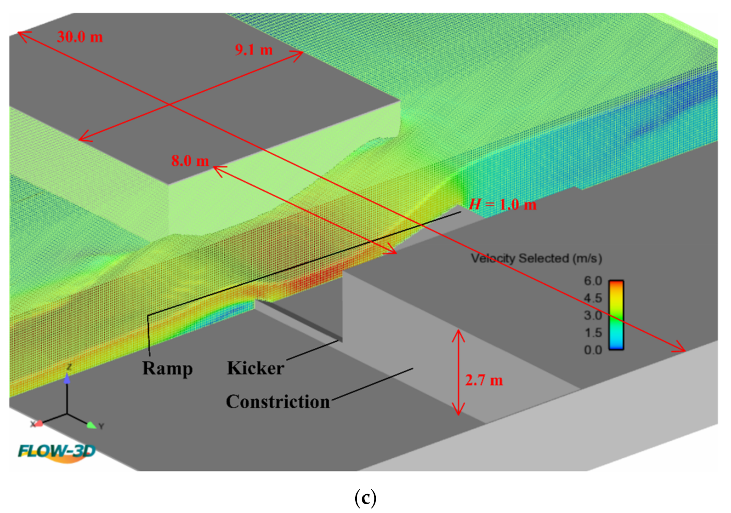
Almost all existing river surf wave research and technologies are applicable at channel drops and downstream pools [28], but drops and downstream pools cannot be found everywhere and it is expensive to create them artificially. Additionally, sediment deposition shortly fills artificial drops and they need expensive maintenance. A surf wave structure suitable for a flat-bed would be preferable, as it would be more widely applicable, easier and less expensive to create and maintain. Accordingly, the objectives of this paper are to introduce a new adjustable hydraulic structure for generation of artificial surf waves in rivers with flat bed, and to assess the sensitivity of the surf wave to structure geometry and flow conditions. This paper presents and evaluates such a structure (Figure 1), recently developed by the third author (Surf Anywhere Consulting Inc.) to form desirable surf waves on flat river bottoms. The structure is assessed via a numerical parametric study, analyzing the sensitivity of the surf wave to different geometric features of the structure and hydraulic boundary conditions. In short, the novelty of this research is to introduce a mechanism for generation of adjustable river surf waves that works on flat bed, which has not previously been addressed in the literature, and to numerically demonstrate the competence of the mechanism and investigate the flow behavior.

2. Methodology

2.1. Mathematical Model and Numerical Solver

For mathematical modeling of the river surf wave flow, the incompressible form of the unsteady Reynolds Averaged Navier–Stokes equations were used as shown in Equations (1) and (2);
V ¯ = 0
V ¯ t + V ¯ . V ¯ = 1 ρ p + υ 2 V ¯ + F b ¯
In which V is velocity, t is time, ρ is density, p is pressure, υ is kinematic viscosity, F b referes to body forces including weight and surface tension, and overbar represents time averaging. A surface tracking algorithm needs to be applied alongside Navier–Stokes equations to achieve the free surface of the flow domain. For this purpose, the Volume Of Fluid (VOF) method was used, an Eulerian method first described by Hirt and Nichols [29]. In this method, the ratio of water and air, referred to as volume fraction (β), is attributed to each computational grid cell. A transport equation (Equation (3)) is needed to simulate the distribution of the volume fraction throughout the domain and the free surface can be drawn as a result.
β t + V . β = 0
To account for turbulence with the RANS equations, a two equation turbulence model with the Boussinesq eddy viscosity assumption is affordable and yields accurate results for simulation of hydraulic jumps [27]. The Standard k ε two equation model (Equations (4) and (5)) that calculates the turbulent kinetic energy ( k ) and the dissipation rate ( ε ) was applied in this research.
ρ k t + ρ k V i x i = x j μ t σ k k x j + 2 μ t e i j e i j ρ ε
ρ ε t + ρ ε V i x i = x j μ t σ ε ε x j + G 1 ε ε k 2 μ t e i j e i j G 2 ε ρ ε 2 k
In which k is turbulent kinetic energy, ε is turbulent dissipation rate, V i is the velocity compotnent in each direction, e i j is component of rate of deformation and μ t ( μ t = ρ C μ k 2 / ε ) is eddy viscosity. Constants in the above equations have been determined to be valid for a wide range of turbulent flows and could be found in the literature as: C μ = 0.09 , σ k = 1.00 , σ ε = 1.30 , G 1 ε = 1.44 , G 2 ε = 1.92 [30].
To compile the described mathematical model and conduct numerical experiments, Flow-3D, a commercial solver package developed by Flow Science Inc. (Santa Fe, New Mexico, USA) was used that utilizes the finite volume method. In two-phase air-water flows, volume bulking takes place and changes the depth, thus affecting momentum distribution [31] and this becomes more critical when investigating flows with steep free surfaces. Therefore, air entrainment/distribution functions were incorporated into physical description of the problem.
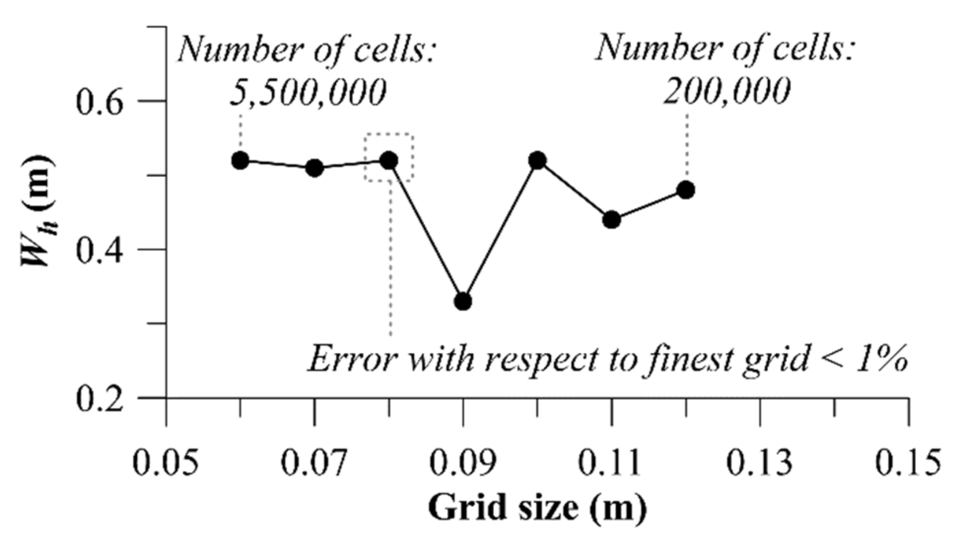
A structured, rectangular hexahedral, topologically orthogonal mesh was used to create the computational space as it is more accurate than the unstructured mesh and more stable when simulating multiphase flows [32]; however, finer mesh had to be selected to capture the edges. Mesh independence analysis was performed and as shown in Figure 2 for cells smaller than 0.08 m, the wave height ( W h ) does not considerably change, thus this value was considered as the grid size for the homogenous single block mesh throughout the computational domain to guarantee the accuracy and minimum computational cost. The spike in the grid size-wave height trend seen in Figure 2 is due to use of a structured rectangular mesh, since for certain grid sizes all edges of a modelled structure may not meet the gridlines of the mesh. As will be seen, the wave height is particularly sensitive to the kicker geometry, and for some grid sizes the kicker in the model mesh was slightly lower, curved or irregular.
A specified volume flowrate boundary condition was set to the upstream face of the computational domain through which pure water (no mixed air) enters the domain steadily. Specified pressure (fluid elevation) boundary condition was set to the downstream face of the domain which allows the tailwater depth manipulation that has principal effect on the surf wave and generally all types of hydraulic jumps. Wall roughness was neglected and no-slip boundary condition was set to solid surfaces of the domain. The boundary layer can be subdivided into three zones based on y + value ( y + = d V τ υ ) which is a function of d , distance from the wall, V τ , shear velocity and υ , kinematic viscosity [31]. A value of y + < 5 designates the viscous sub-layer where V V τ is lineally correlated with y + . Values of 5 < y + < 70 indicates the buffer zone where laminar and turbulence features both exist and y + > 70 is the log-law region where the velocity profile is logarithmic. A wall function can be applied instead of directly modeling these regions that allows coarser mesh and less computational cost. The requirement for accurate application of the wall function is the wall adjacent cells should reside in the log-law region. Post-simulation checking of simulated flow field shows that the selected grid size in this study (i.e., 0.08 m) satisfies this condition.

2.2. Calibration

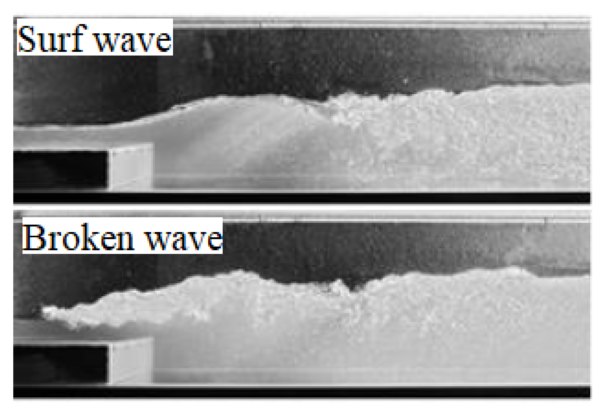
Numerical simulation of surf waves requires initial input of uncertain values to the model that can only be determined by comparing results with a corresponding real-world event. Calibration plays a more important role when modeling surf waves comparing with most other hydraulic phenomena as these waves are on the fragile boundary of two different hydraulic states (Figure 3), so that a minor deviation in introducing a value to the model completely changes the flow pattern. River surf waves appear where a supercritical flow transforms into a subcritical flow, conventionally known as a hydraulic jump. A classic hydraulic jump is a non-surfable highly turbulent region of air-water mixed flow with recirculating currents on the surface and significant energy dissipation. However, in special geometric and hydrodynamic arrangements, supercritical flow can overrun above the slow subcritical flow in the form of a crystal fast upward jet, followed by diving/dispersion of the fast core and air entrainment into the downstream slower water body (Figure 3). The upward crystal jet in its steepest state, before breaking into a conventional hydraulic jump, is the ideal surf wave, but a small change can break the wave into a conventional hydraulic jump (broken wave). Koch [24] modeled such waves in the laboratory on an abrupt drop with an adjustable flap at the edge, which is numerically modeled herein for calibration purposes.
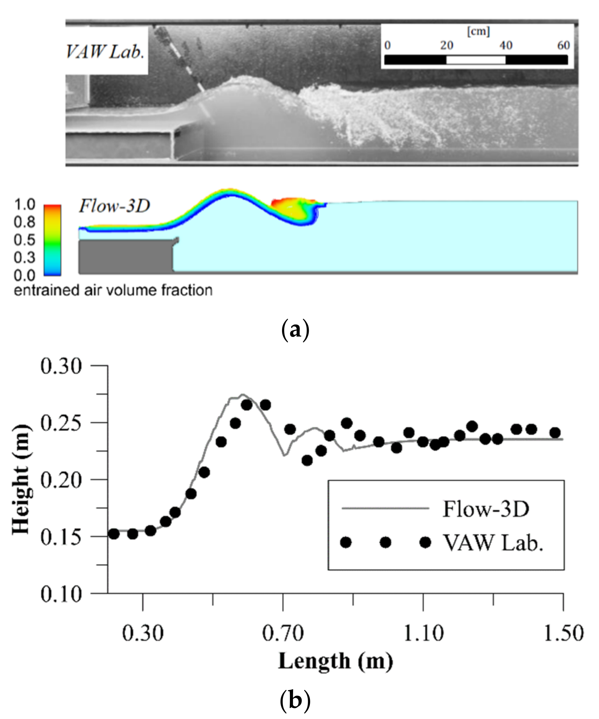
The laboratory physical model was in a rectangular flume with 0.1 m abrupt drop, and a 0.025 m flap at the drop edge set at 30° with respect to horizontal, at the Laboratory of Hydraulics, Hydrology ad Glaciology (VAW) at ETH Zurich. A 0.05 m deep, horizontal supercritical flow with velocity of 1.75 m/s approached the drop. Experiments showed that a maximum tailwater depth of 0.242 m produced the highest surf wave and further tailwater depth broke the wave. The described experiment was numerically reproduced in this work and the maximum tailwater depth that could be achieved before wave breaking was found to be 0.235 m. The turbulence model, air entrainment rate coefficient, escape rate coefficient, initial bubble diameter and minimum volume fraction of water phase were manipulated to gain the nearest tailwater depth to the laboratory model before breaking the wave, yielding a numerical maximum tailwater depth only 2.9% smaller than that in the physical model. Figure 4 shows a comparison of laboratory and numerical surf wave after the calibration.
The objective function in the calibration procedure was matching numerical and physical tailwater depth. Even though the tailwater depth in the calibrated numerical model is 2.9% smaller than that in the physical model, the numerical wave is slightly higher and steeper. Manipulation of parameters to produce a numerical wave with closer height and steepness, or air distribution pattern, to the physical model was possible, but the tailwater depth (downstream boundary condition) would have differed more from the physical model. During this calibration the Standard k ε model yielded more satisfactory results than either the RNG k ε or k -w models since both latter cases break the surf wave into a conventional hydraulic jump (Figure 3) at the same boundary condition.

2.3. Parametric Analysis

The geometry of the structure (Figure 1) is codified by: ramp height ( H ), ramp length ( R ), transition length ( T ), kicker length ( K ) and angle of the kicker (ψ). Wave height ( W h ), wave slope ( S ) and depth averaged velocity at the kicker tip ( V k t ) are characteristics of the surf wave. Flowrate per unit width ( q ) and tailwater depth ( T w ) are flow features (hydraulic boundary conditions). Gravitational acceleration ( g ), dynamic viscosity of the fluid ( μ ), and fluid density ( ρ ) are ambient and fluid properties. Equation (6) shows all the influential variables in this study in functional form:
f W h ,   S ,   V k t ,   H , R , T , K , ψ ,   q , T w ,   g ,   μ ,   ρ = 0
Phenomenologically, river surf waves are a form of hydraulic jump. Ohtsu et al. [34] showed that in hydraulic jumps at q ρ μ   > 6.5 × 10 4 the Reynolds number does not affect the flow and it will be governed by Froude number [35]. In all experiments of this research q ρ μ was greater than 4 × 10 6 . H , g and ρ were selected as repeat variables, applying the Buckingham π theorem, Equation (6) could be rearranged in dimensionless form to show the wave parameters as a function of the structure geometry and hydraulic boundary condition parameters as shown in Equation (7):
W h H ,   S , V k t g H = f   ( R H ,   T H ,   K H ,   ψ ,   T w H ,     μ ρ g H 3 , q g H 3 )
In this research, parameters on the right hand side of the Equation (7), except   μ ρ g H 3 due to independence of the flow from viscous effects, were varied in a parametric analysis to investigate the effect on surf wave features. Although Froude number ( V g y in which y is the flow depth) did not appear among the dimensionless parameters, it will be used in the following to explain the flow condition in downstream pool (downstream of the surf wave) using velocity and depth at the downstream boundary and it will be referred to as F r d o w n s t r e a m . It is a common practice in hydraulic jump research to use upstream Froude number (supercritical section) to characterize the behavior of the hydraulic jump, but the trough depth (supercritical depth upstream of the jump) is a function of the ramp height ( H ) and flow per unit width ( q ), thus cannot come among the independent elements for the dimensional analysis. This is due to emphasis on keeping geometric features (specifically ramp height) of the structure in formulation since the main purpose of this research is seeking sensitivity of the surf wave to adjustment of geometric features. Independently, it is worth noting that the Froude number of the trough (supercritical section upstream of the surf wave) changed from 1.66 to 2.73 in the numerical experiments of this research.
The complete matrix space of parameter combinations was not tested, (a) to avoid numerous time-consuming 3-D CFD simulations, and (b) because many scenarios of a full solution space will result in formation of a conventional hydraulic jump rather than a surf wave. Instead, parameters were varied systematically in a phase-by-phase approach based on degrees of freedom in the design process. In other words, geometric parameters that are more difficult to be used for wave adjustment at prototype scale were investigated first and considered to be fixed for subsequent experiments. The sophisticated phase-by-phase variation of parameters employed herein revealed extremes, such as maximum tailwater depth that leads to maximizing the wave height, beyond which the surf wave breaks into a hydraulic jump. Admittedly, the found extremes are valid only for the particular geometric arrangement established for that phase, but the parameters that have already been fixed are less likely to be used for wave adjustment in practice or to have a considerable effect on the wave.
Initial values for the geometry of the wave structure and the hydraulic boundary conditions were adopted from a prototype river surf wave, “The Mountain” in Kananaskis River in Alberta, Canada, which has been constructed by suitably arranging boulders on the riverbed to create a flow contraction. The ramp height is the most independent variable so that a higher ramp is desirable as it provides more energy input to the system, but it needs to satisfy a constraint of not being too high to flood upstream banks. Once ( H ) is calculated according to described conditions, every other parameter needs to be calculated as a function of ( H ). Unit width discharge ( q ) for most successful existing human-made surf waves is between 2 to 4 m3/s/m [36] which has been covered in the experiments of this research ( q m a x = 4   m 3 / s / m ) and could be achieved in practice by constricting the river width. The tailwater depth can be changed from the initial value, normal depth of the river, to a maximum value in which the surf wave breaks into a conventional hydraulic jump. In this research, tailwater depth ranged from the normal depth of the Kananaskis River and iteratively increased to meet the maximum value. Tailwater depth adjustment takes place by stop-logs or coffer dams in practice which is not shown in Figure 1. While the modelling has been parameterized using this case study, the dimensionless results are generalizable to other locations.

3. Results

A surf wave generated by the explained mechanism in a river with flatbed (no drop) is affected by parameters such as adjustable ramp, transition, adjustable kicker, tailwater depth and flowrate. This parametric study seeks to demonstrate sensitivity of the wave to these geometric and hydraulic features through numerical experiments.

3.1. Ramp

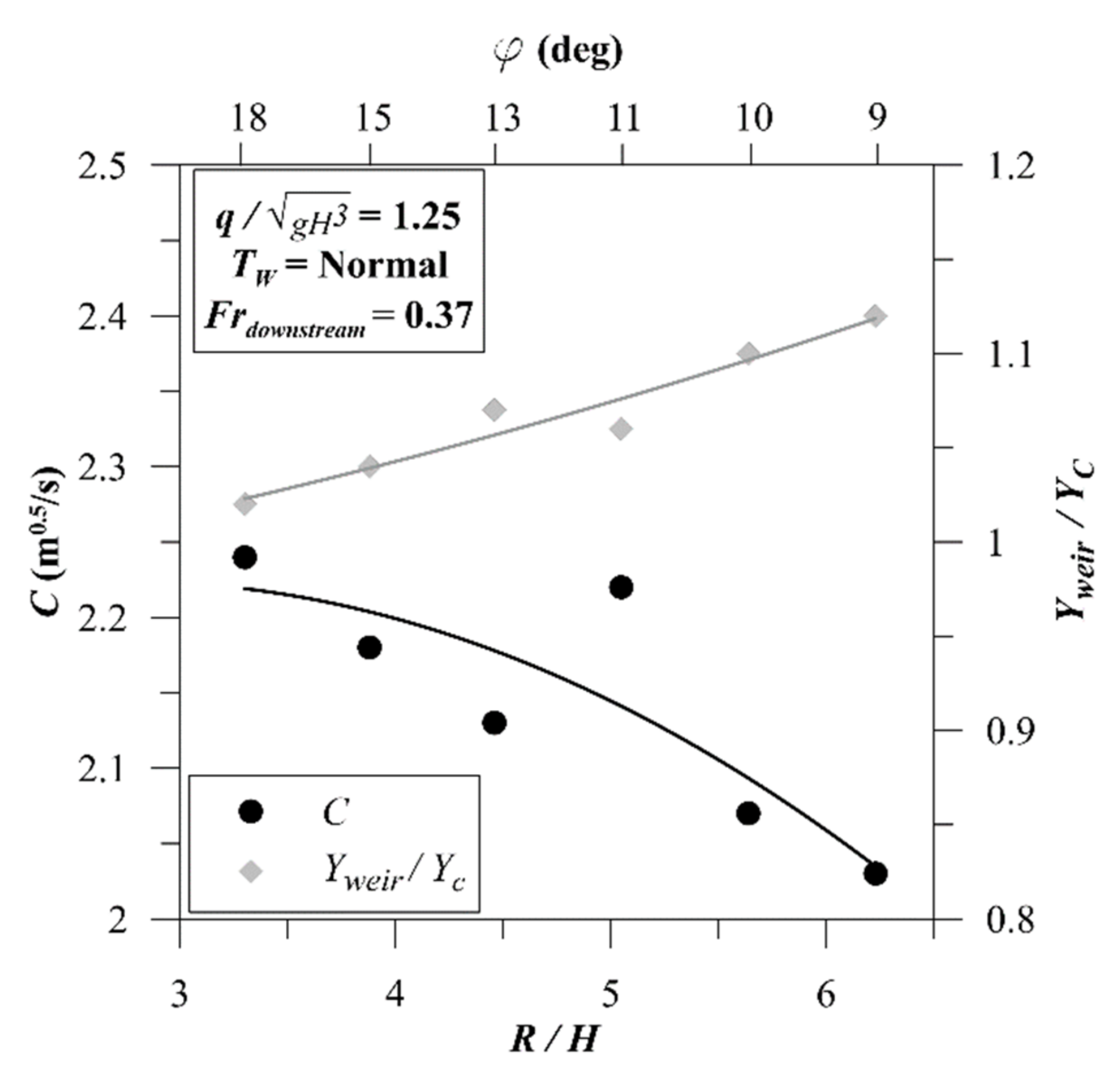
The ramp height, alongside the flowrate, determines the energy input to the system and guarantees safety of upstream regions from flooding at the maximum surfing flowrate. The height of the ramp was not changed for the sensitivity analysis, because the highest possible ramp could be selected to achieve maximum acceleration and stronger waves, but the length of the ramp ( R ) was changed when the height was constant for the sensitivity analysis. Note that in higher flowrates and flood condition, adjustment jacks under the ramp could be utilized to flatten the ramp and minimize the resistance. To have the maximum ramp height, weir equation; E = Q / ( C . L ) 2 / 3 in which E is the water head over the weir (neglecting the velocity), Q is the flowrate, C is weir coefficient and L is the length of the weir, could be applied to calculate the water head over the ramp crest and compare with river capacity to prevent flooding. For this calculation weir coefficient ( C ) is required; which numerical experiments of this research showed that on average C = 2.15 (m0.5/s) when ramp slope is between R / H = 6.23 (ϕ = 9°) and 3.30 (ϕ = 18°) (Figure 5). The ratio of water depth on weir crest to critical depth decreased from 1.12 to 1.02 as R / H decreased from 6.23 (ϕ = 9°) to 3.30 (ϕ = 18°) which implies that the ramp crest cannot be considered as a control section.
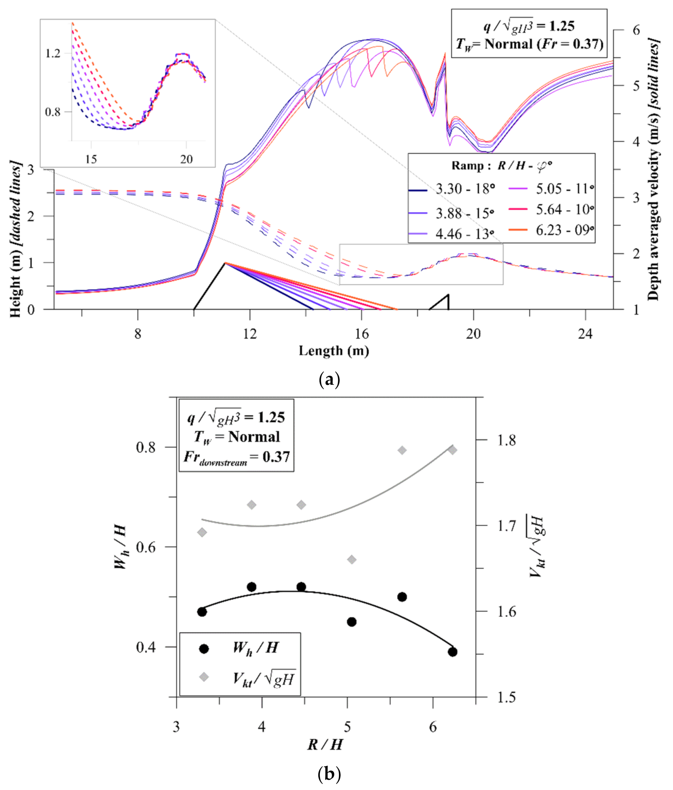
Figure 6 shows how different ramp lengths ranging from 3.3 to 6.2 times longer than ramp height could affect wave profile and velocity distribution. In R / H = 3.30 (ϕ = 18°) and 6.23 (ϕ = 9°) the wave peak elevation is lower than for intermediate ramp slopes; however, the more influential effect of ramp slope is on trough elevation. Longer ramps lead to shorter transition in which the supercritical flow does not have enough space to fully develop, thus leading to undesirably higher water surface elevation in troughs. Taking the highest wave peak and lowest trough and the shortest possible ramp as the favorable condition, R / H = 3.88 (ϕ = 15°) was found to be the best value among other experiments. The other parameter that should be checked is the flow velocity in the surf section. On-site flowrate and depth measurements of existing river waves have shown that appropriate surf waves have depth averaged velocity around 5 m/s. Figure 6 shows that the velocity at the kicker tip is a local maximum in the range of 5.2 to 5.6 m/s, increasing with the ramp length. In other words, the milder the ramp, the higher the depth averaged velocity at the kicker tip; however, the change is not intense and a 100% increase in ramp length increases the velocity by less than 8%. Analyzing the sensitivity of the wave to ramp slope according to Figure 6b shows that while R / H   = 3.88 (ϕ = 15°) provides marginally less velocity at the kicker tip, this is the preferred ramp steepness because it provides the maximum wave height with the minimum material for construction.

3.2. Transition

To show how transition length affects the surf wave, different transition lengths at different flowrates were examined. With a ϕ = 15° ramp, transition length to ramp height ( T / H ) was changed from 0.83 to 4.91 and examined under three different flowrates. Figure 7a shows that the flow leaving the ramp continues to accelerate on the horizontal bed of the transition, thus decreasing the trough depth. Therefore, a minimum transition length is required for complete development of the trough. Additionally, wave peak increases with initial elongation of the transition. However, an undesirable H3 profile (i.e., increasing supercritical flow depth along a horizontal bed) begins to develop with a longer transition. The choppy surface of the wave profile in Figure 7a is due to numerical resolution and a smooth surface is expected in prototype; nevertheless, this resolution gives sufficient accuracy for understanding wave profile sensitivity to related parameters.
As shown in Figure 7b, increasing R / H from 0.83 to 4.91 increases the wave height and decreases the wave slope. Results also show that the depth-averaged velocity at the kicker tip is independent of the transition length. Thus, selecting a transition length is a compromise between maximizing wave height and wave slope since they showed opposite trend. the required transition length for full development of the trough that yields maximum wave height can be expressed as T / H = 3.55 . Admittedly, however, the wave steepness is not maximum at this transition length.

3.3. Tailwater Depth

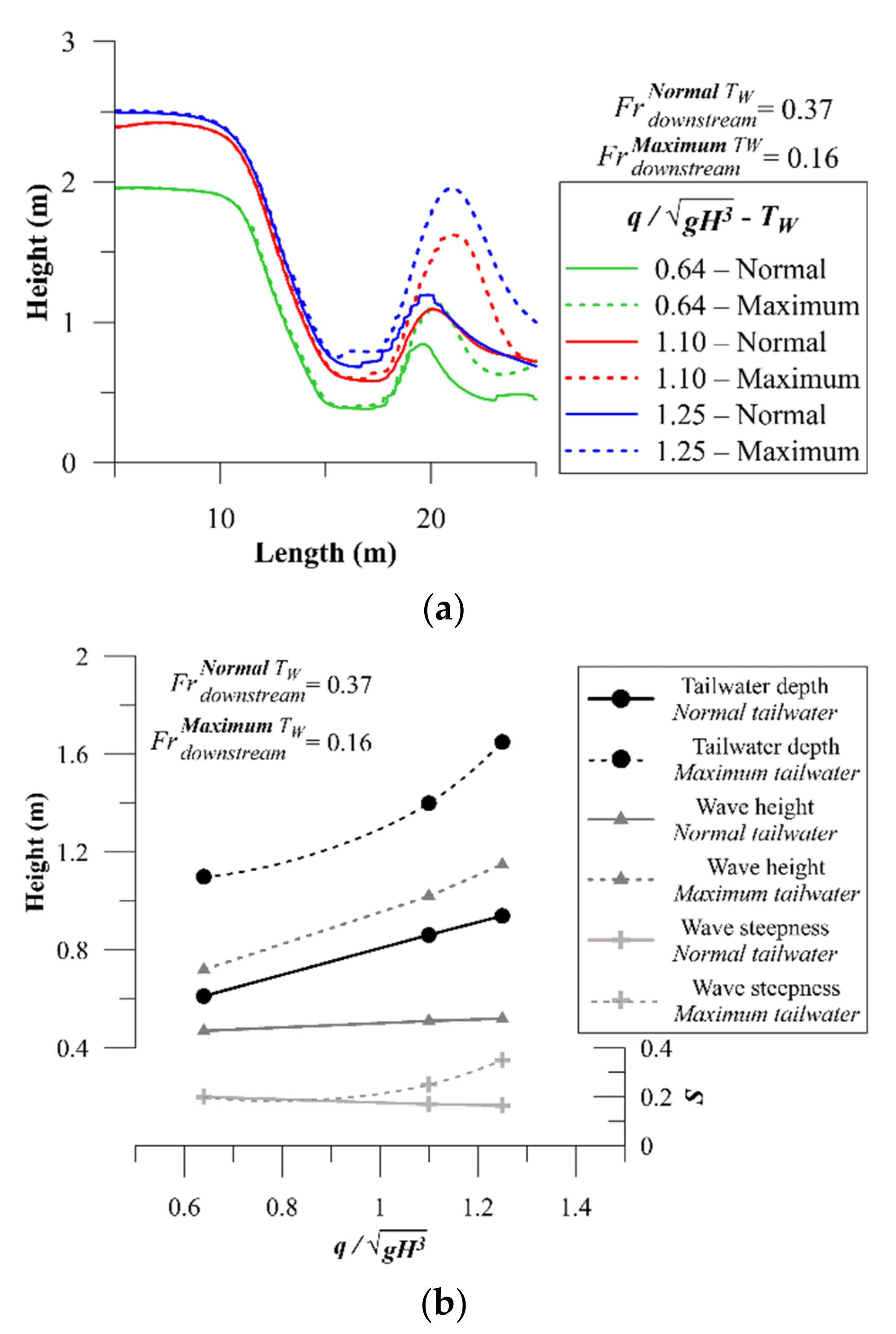
A parameter that significantly affects the wave height is tailwater depth. Naturally, the tailwater depth downstream of the wave structure is the normal depth of the river. By means of regulating structures such as simple stop-logs or coffer dams the tailwater depth could be increased to augment the wave. Structure geometry, ϕ = 15° and T / H = 3.55 , was taken from the previous steps and the tailwater depth (downstream boundary condition of the numerical model) was increased in increments of 0.05 H to find the maximum tailwater depth before the wave breaks at different flowrates. Nearby gauge data, local measurements, and observations at the prototype wave site in Kananaskis River were used to calculate the normal depth as the downstream boundary condition for flowrates from 32 m3/s ( Q m a x ) to 16 m3/s ( 0.5 Q m a x ). The Froude number calculated using these normal depths varies from 0.374 to 0.356, respectively, which will roughly be referred to as 0.37 hereafter due to its slight variation. Figure 8 shows how increasing tailwater depth from normal to maximum value affects the wave. Note that Figure 8a shows only the surf wave while omitting the downstream water surface fluctuations, but tailwater elevation (downstream boundary) can be observed in Figure 8b. For the range of flowrate from 0.5 Q m a x to Q m a x the ratio of maximum tailwater depth to normal tailwater depth is approximately 1.7. At maximum tailwater depth, where the wave is at the threshold of breaking, downstream Froude number varies from 0.161 to 0.148 for flowrate changing from Q m a x to 0.5 Q m a x . Due to slight variation of Froude number at maximum tailwater depth, it will roughly be referred to as 0.16 hereafter regardless of the flowrate. At Q m a x and maximum tailwater condition, tailwater depth is 60% larger than ramp height, yet the wave is not broken. Wave height as the most important parameter in designing a surf wave showed no significant change by flowrate when tailwater depth is normal. However, in maximum tailwater condition, increase in flowrate considerably increases the wave height. In other words, increasing the tailwater depth not only increases the wave height, but also makes the wave height sensitive to flowrate. The tailwater depth as the major parameter affecting the wave height could increase the wave height by up to 2.2 times the initial value. This increase in wave height is also associated with increase in wave steepness.

3.4. Kicker Geometry

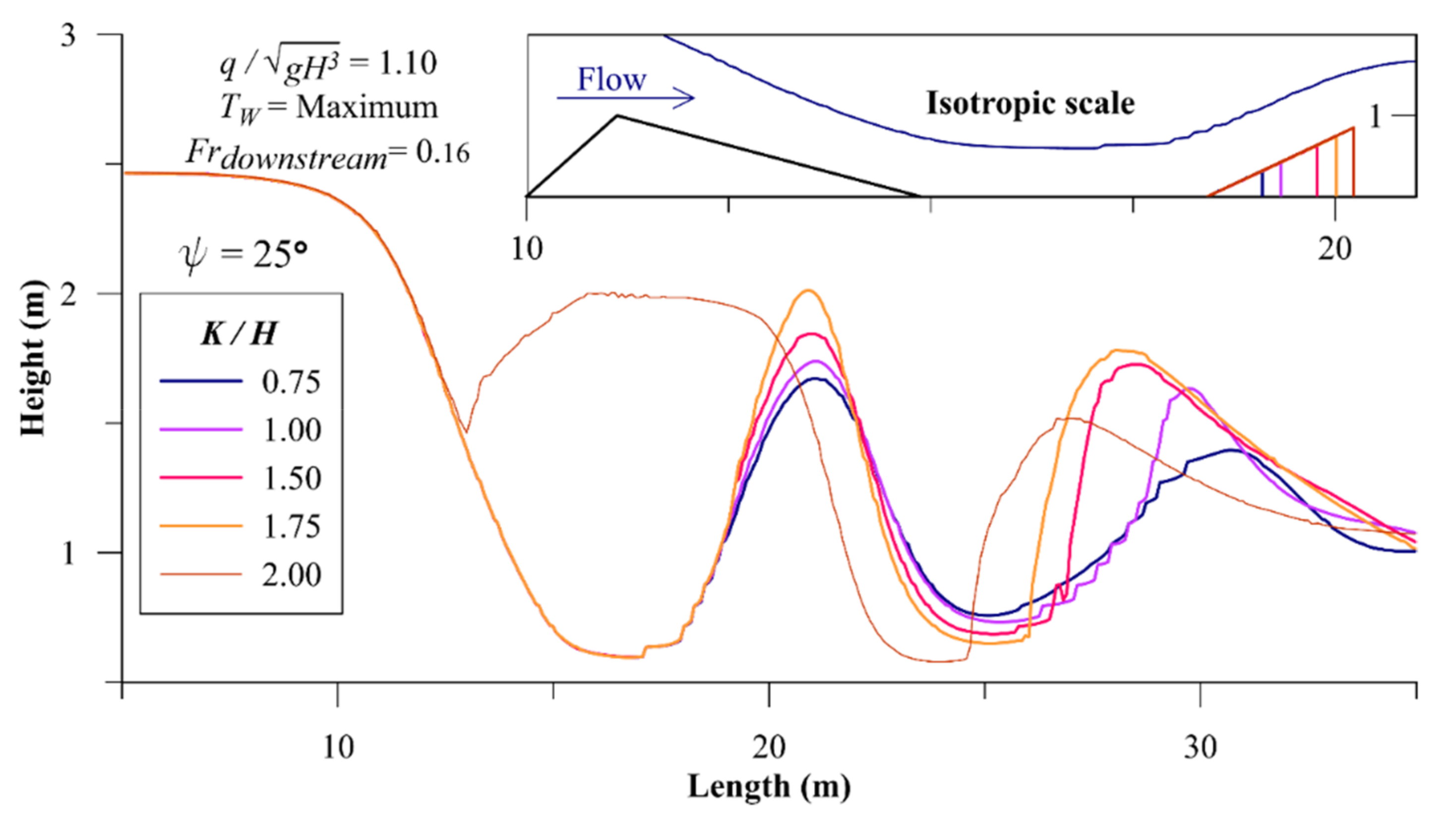
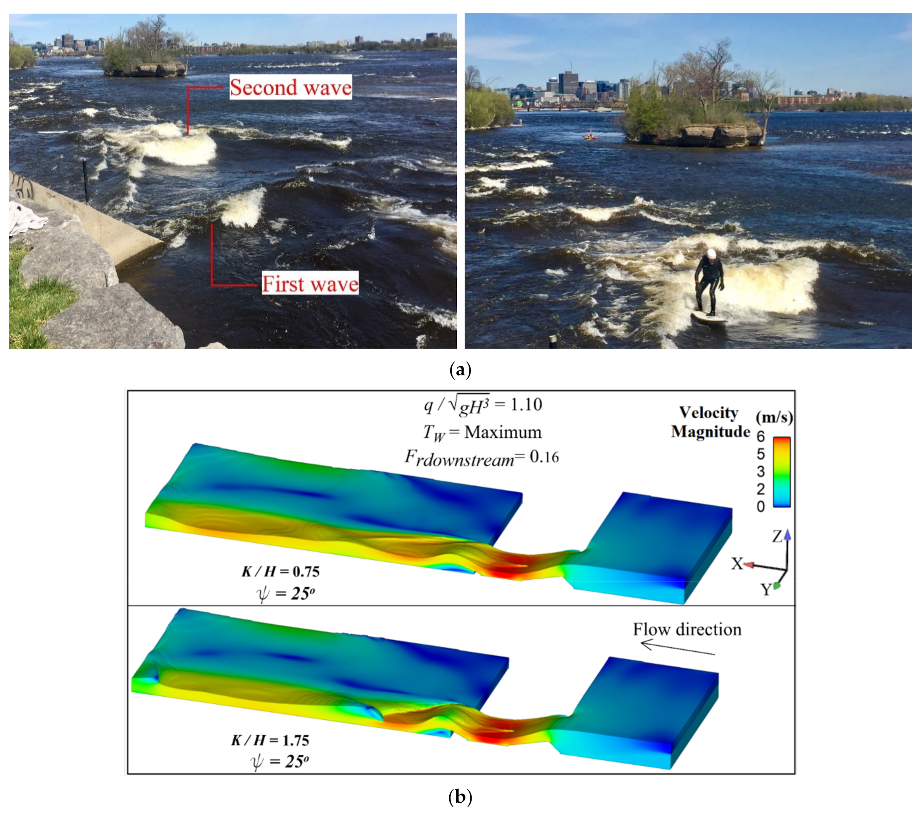
The kicker as the lightest element of the wave generation setup should be considered adjustable for easy wave manipulation with minimum force and cost. The recommended ramp slope, transition length and tailwater depth found in the previous steps were kept constant and kicker geometry was changed to show how it affects the wave. A kicker may be enlarged by keeping the angle; (ψ) constant and increasing the length ( K ) or keeping the length constant and increasing the angle. Figure 9 shows that increasing kicker length increases both wave height and steepness. At the constant angle ψ = 25°, increasing K / H from 0.75 to 1.75 increased the wave height by 30% and steepness by 80%. The wave breaks if K / H exceeds 1.75. Kicker geometry also significantly affects the second wave. In certain range of geometric and hydraulic boundary conditions the first wave (over the kicker) is not a hydraulic jump; rather, the flow leaving the kicker section remains supercritical leading to formation of a wave train in the downstream pool. Figure 10a shows an example wave train, naturally existing in Ottawa River, with a surfer on the second wave. Figure 9 shows how elongation of the kicker augments the second wave and brings it to break. Figure 10b shows 3-D velocity fields, cut along the longitudinal axis, for shorter and longer kickers. A triangular pattern around the broken apex of the second wave, resembling the Ottawa River wave, can be seen in the flow field with the larger kicker, vividly demonstrating the effect of kicker enlargement on increasing height and steepness of the first and second wave.
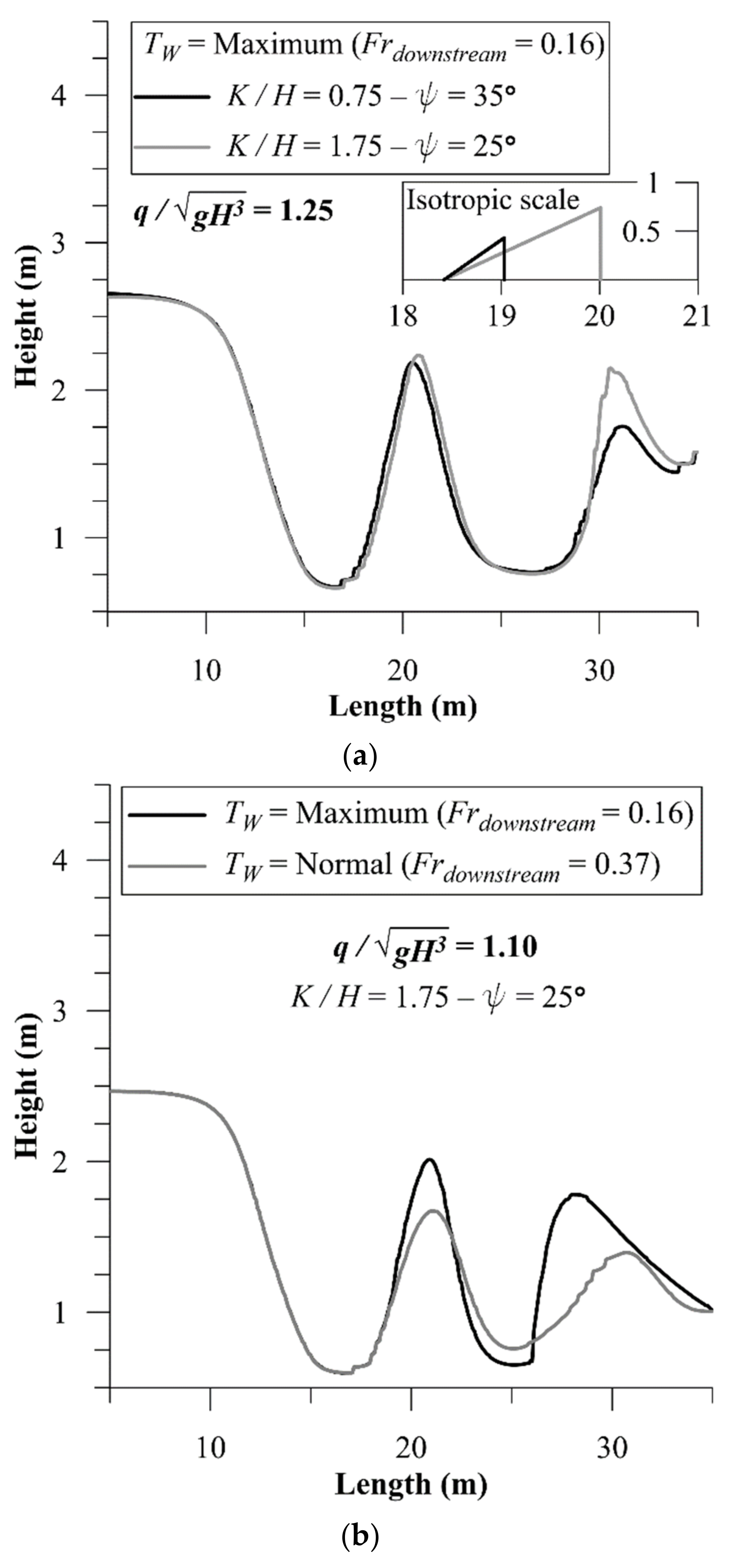
Another approach for enlargement of the kicker to maximize the surf wave is keeping the length constant and increasing the angle (ψ). A set of experiments at K / H = 0.75 with 5-degree increments of kicker angle was conducted to find the maximum kicker angle without wave breaking. Figure 11a compares waves generated by the kicker of the maximum length versus the kicker of the maximum angle. The “first wave” generated by maximum kicker length ( K / H = 1.75 , ψ = 25°) has almost the same height and steepness as the first wave generated by maximum kicker angle ( K / H = 0.75 , ψ = 35°). However, the longer kicker has a higher vertical projected height than the steepest kicker and the second wave is significantly higher and steeper in case of using the longer kicker.
Since the kicker is the easiest element to manipulate in a wave generation mechanism, it may be adjusted to compensate for changes in flowrate or tailwater depth. Figure 11b,c show how extreme kickers respond to reduction in tailwater depth and flowrate. Figure 11b compares wave profiles with the longest kicker when tailwater depth is maximum versus at normal. The maximum length of the kicker found in maximum tailwater condition brought the wave to the threshold of breaking, yet Figure 11b shows reduction in the tailwater to normal does not break the wave. Furthermore, with the initial kicker (not optimized size; K / H = 0.75 , ψ = 25°) reduction in the tailwater from maximum to normal reduced the wave height more than 60% (Figure 8), but with the extreme kicker the corresponding value is about 30% (Figure 11b).
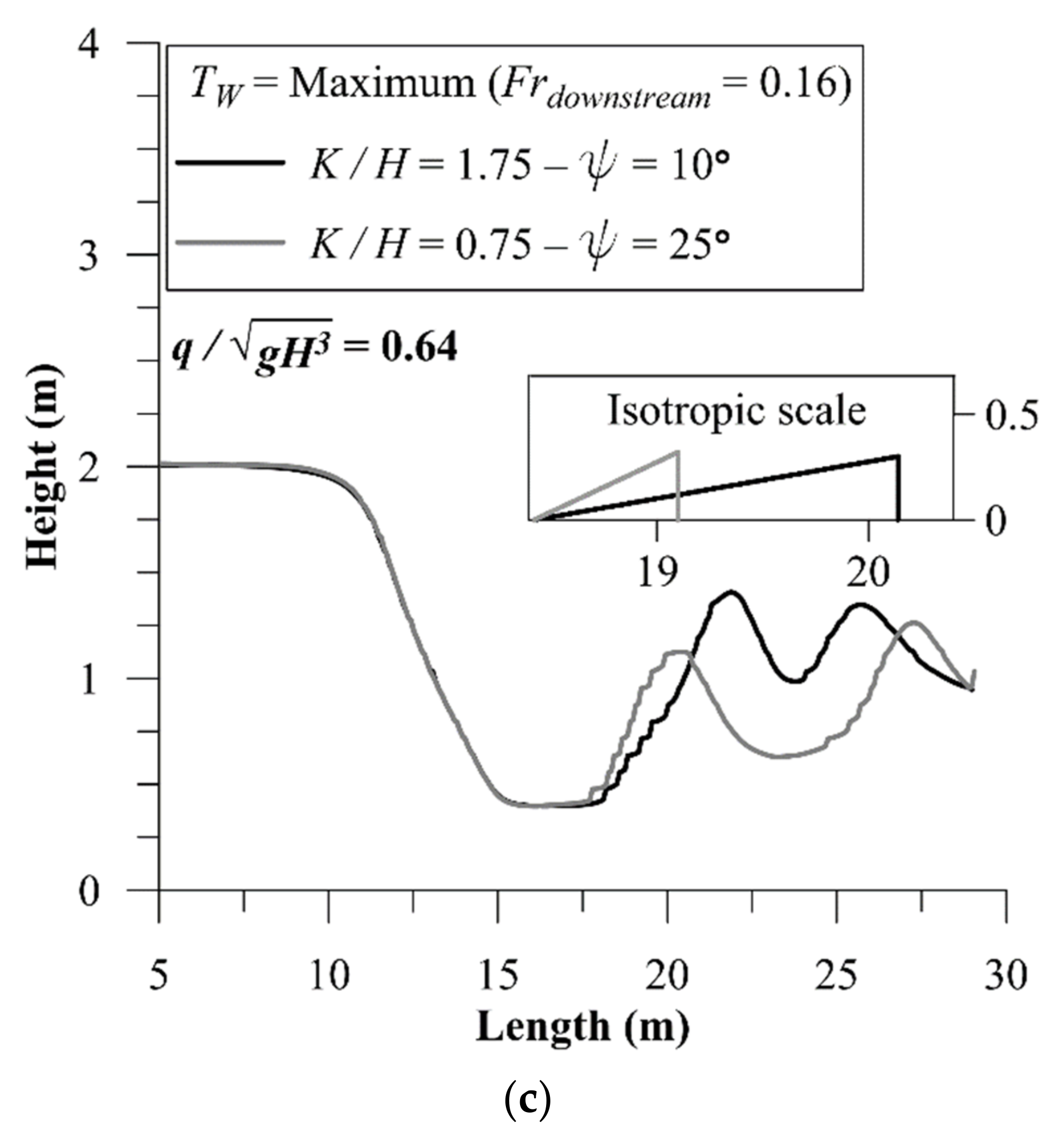
To examine the effect of flowrate reduction when using extreme kickers, flowrate was reduced from 0.87 q m a x to 0.5 q m a x . Unlike tailwater reduction, flowrate reduction led to breaking waves when using an extremely long or extremely steep kicker that have been proved to be functional for the higher flowrate. Thus, when using extreme kickers, they must be readjusted as the flowrate changes. In lowered flowrate, kicker geometry was again manipulated and the new adopted extreme kickers were found to be K / H = 1.75 , ψ = 10° (extremely long) and extremely steep: K / H = 0.75 , ψ = 25°. These two extreme kickers have almost similar vertical projected height, but the resultant wave of extremely long kicker is higher and less steep than that of extremely steep kicker (Figure 11c).

4. Discussion

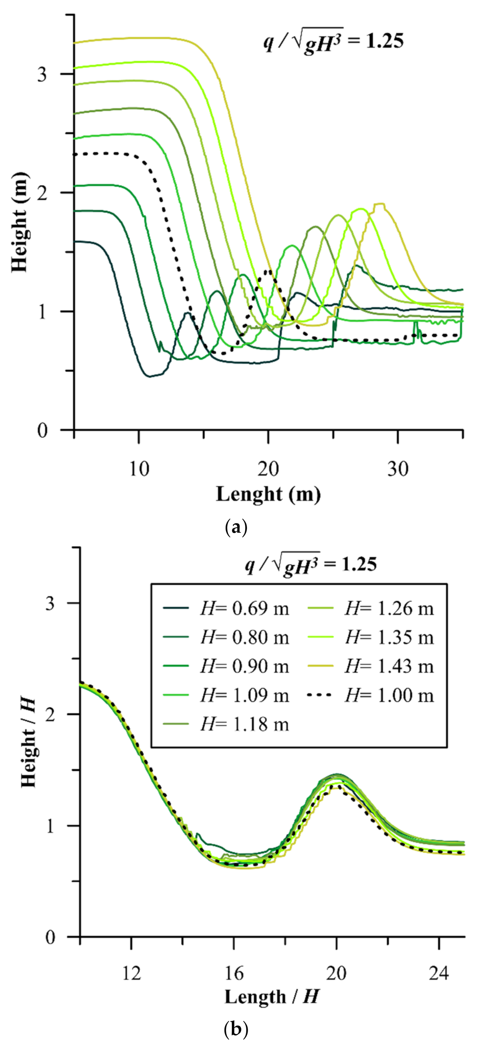
As mentioned above, depending on site considerations the highest feasible ramp is desired, thus in the present numerical experiments ramp height was kept constant at 1 m, since any higher ramp would have induced overbank flooding at the prototype. Nonetheless, a criterion is needed to attribute findings of this research to other sites where shorter or higher ramps are needed. A dimensionless group, ( q g H 3 ) that correlates the ramp height to flowrate was evaluated as the similarity criterion. By keeping the q g H 3 = 1.25 constant, where H is higher or shorter than 1 m, a corresponding q could be calculated. Figure 12 shows that if the structure height changes and all other geometric features such as ramp length, transition length, kicker length and tailwater depth are changed proportionally, and the scaled flowrate based on similarity of ( q g H 3 ) runs over the structure, a similar, scaled wave profile is predicted. Flowrate adjustment can take place by constricting the river width or bypassing a portion of the flow. The average, point by point discrepancy, of profiles in Figure 12b is only 6.75%.
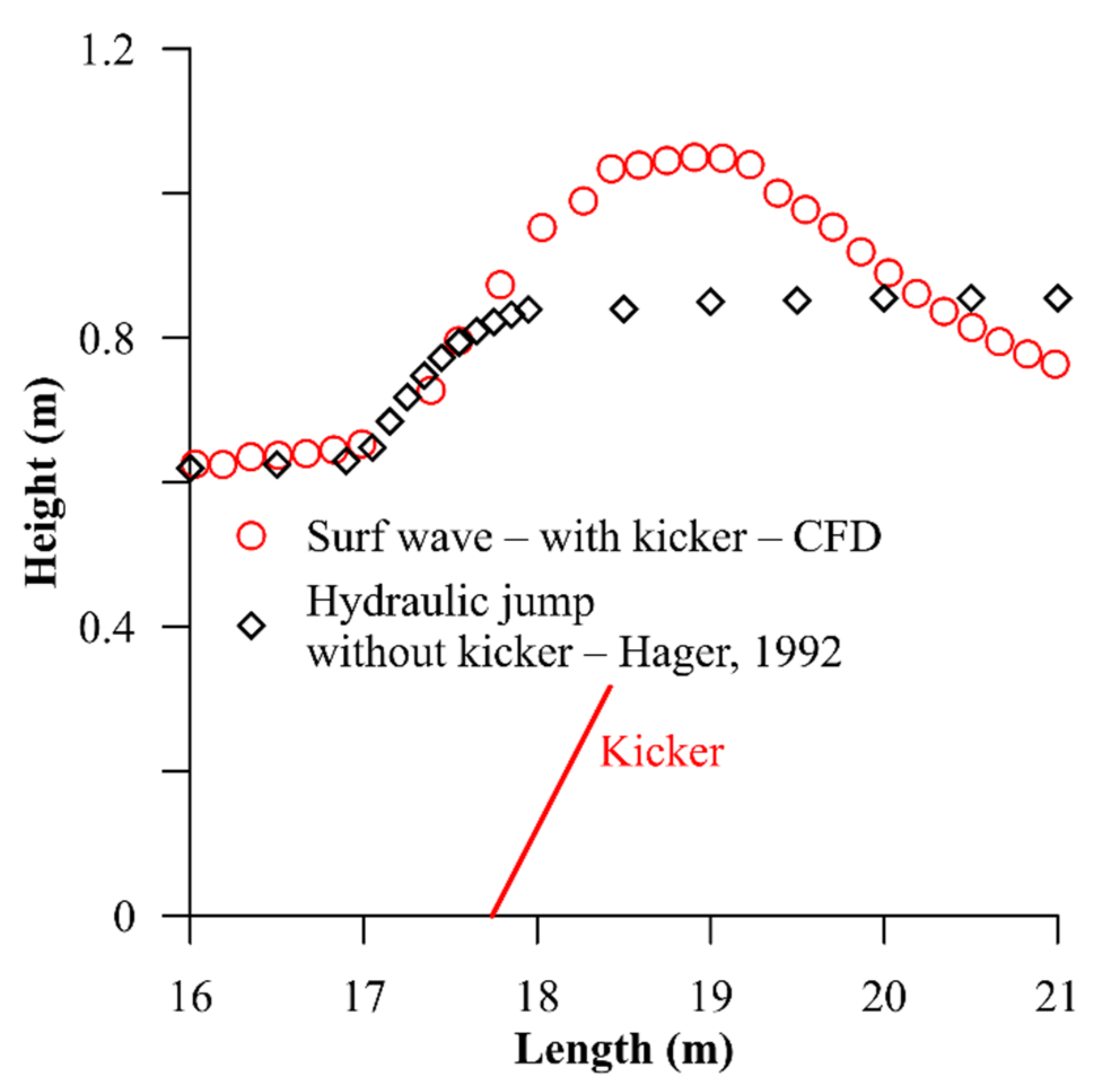
As discussed in this paper, kickers have the principal role in generation of surf waves, so that without kickers the surf wave reforms to a conventional hydraulic jump with surface rollers and severe air entrainment. In order to show this, suggested equations in the literature ([37]—Equations (1) and (6)) were utilized to draw the water surface profile of the conventional hydraulic jump in the absence of the kicker to be compared with the corresponding surf wave. It is considered corresponding because the trough and downstream (tailwater) depth and velocity of the surf wave were used in Hager’s equations as input to derive the free surface profile of the hydraulic jump. These two depths do not satisfy the classic Belanger equation [38] for calculation of the conjugate depths of the hydraulic jump, because a channel expansion exists and therefore the specific discharge is different between the trough and the downstream boundary. Figure 13 compares the free surface profile of the corresponding surf wave and hydraulic jump.
As shown in Figure 13 the conventional hydraulic jump connects the supercritical to subcritical section in a much shorter distance, however the graph does not show the associated air entrainment and intense energy dissipation. However, in case of surf wave, the kicker helps the water surface to rise from the supercritical section to a level beyond the downstream subcritical depth without a hydraulic jump (the change to subcritical is smooth with a crystal-clear water body without surface rollers). The theory and physics of this phenomenon has been previously explained by Kabiri-Samani et al. [39]; Kabiri-Samani and Naderi [40]. Following the crest of the surf wave, the water surface level falls again to a supercritical value where a conventional hydraulic jump takes place to facilitate the transition to the subcritical downstream boundary. The location and intensity of this jump depends on the tailwater and kicker specifications as could be seen in Figure 10b.
The CFD analysis in this research had both strengths and limitations. The major strength of the CFD was facilitation of undistorted modeling. Since this scheme of wave generation involves river constriction, and constriction determines the Froude number change in the wave canal and downstream pool, transverse scale matters in addition to longitudinal profile scale. In typical hydraulic laboratory experiments, it is not usually possible to achieve a full undistorted model of a river process without sacrificing depth to prevent domination of the surface tension. CFD provided a full undistorted model of the river wave. Furthermore, the CFD approach enabled flexible parametric change of structure features and easy output of desired parameters throughout the flow field, both of which are expensive and time-consuming to achieve in a physical model. On the other hand, calibration of the CFD model with laboratory data showed difficulties with modeling air entrainment. In the CFD model, the entrained air does not penetrate and distribute throughout the water body as observed in physical models. This problem could be solved by decreasing the initial bubble diameter, which is an input parameter to the model that reduces the buoyancy of bubbles. However, it was observed during model calibration that manipulation of model parameters to better simulate air entrainment and distribution deviated the wave water surface profile from the observed data. Air entrainment occurs downstream of the surf wave and to understand how it can affect the wave profile one can consider the surf wave in a control volume with balanced forces as the flow is steady. External force exerting on the downstream face of this control volume is a function of the ambient fluid density which considerably varies due to air entrainment. Thus, accuracy of the air entrainment was sacrificed to achieve a more reliable wave profile. However, correctly simulating the associated air process is principally important in analysis of the wave safety.
After studying influence of all relevant parameters on wave shape and codifying wave behavior, flowrate and tailwater were reduced dramatically to assess wave resilience and to check if the wave breaks for a parameterization. Results suggest that once the kicker is set in extreme position it need not be readjusted for reduction in tailwater depth but it should be readjusted in response to reduction in flowrate. This is important since kicker adjustment may be manual, labor-intensive, and require shutting down the river flow. Note that manual adjustments are preferred not only because of lower cost, but because application of hydraulic or pneumatic jacks in a river poses a more complicated environmental permitting process.

5. Conclusions

An innovative mechanism was introduced herein to generate adjustable surf waves in flat bed rivers (no drop) and sensitivity of the wave to geometric and hydraulic parameters was investigated numerically. Average weir coefficient of 2.15 m0.5/s was found to be valid for calculation of water head over the ramps of different slope. Results demonstrated slight sensitivity of the wave to ramp slope and the recommended value that maximizes the wave and minimizes the cost was found to be R / H = 3.88 (ϕ = 15°). The transition, which is the horizontal distance between ramp toe and kicker, should be long enough to facilitate full development of the trough, but no longer to inhibit development of a H3 profile. Numerical experiments of this research recommend T / H = 3.55 for a range of q g H 3 = 0.64 to 1.25. Results showed that although the ramp slope does not have significant effect on the wave profile, tailwater depth could significantly augment the wave. As an estimate of maximum tailwater depth, which could be provided by means of regulating structures downstream, the results showed maximum tailwater depth can be 60% higher than the ramp crest. Increasing the tailwater depth from normal depth to the maximum value can double the wave height. The kicker is the most convenient design element for readjustment and results showed the wave has considerable sensitivity to this geometric parameter. The surf wave can be brought to the threshold of breaking by either elongating or steepening the kicker. In the range of numerical experiments reported herein, extreme kickers were found to be K / H = 0.75 , ψ = 35° (steepest), and K / H = 1.75 , ψ = 25° (longest).

Author Contributions

Conceptualization, N.E. and P.A.; Methodology, C.D.R.; Simulation and Analysis, P.A.; Supervision, C.D.R. and N.E.; Writing—original draft, P.A.; Writing—review and editing, C.D.R. and N.E.; Funding Acquisition P.A. and N.E.; Project Administration, C.D.R. All authors have read and agreed to the published version of the manuscript.

Funding

This research was funded through the MITACS Accelerate program. Authors would like to appreciate MITACS for financial contribution (Application Ref: IT15884—Funding Request Ref: FR42145) in project entitled: “Redefining Recreational River Waves”, and Surf Anywhere Consulting Inc., a Calgary-based Tech. Company for financial contribution.

Institutional Review Board Statement

Not applicable.

Informed Consent Statement

Not applicable.

Data Availability Statement

Some data and models that support the findings of this study are available from the corresponding author upon reasonable request. (Water surface profiles, velocity distribution and hydraulic boundary condition).

Acknowledgments

Jacob Kelly Quinlan, Wave and Culture Explorer, and Ryan Richards, Wave Technician and Wave Design Consultant both from Surf Anywhere Consulting Inc. are appreciated because of their insightful comments on design of experiments and interpretation of results.

Conflicts of Interest

The authors declare no conflict of interest.

Nomenclature

The following symbols are used in this paper:
C weir coefficient
d distance from the wall
E water head over the weir;
e i j component of rate of deformation;
F b body forces;
F r d o w n s t r e a m Froude number of the flow downstream of the wave;
g gravitational acceleration;
H ramp height;
K kicker length;
k turbulent kinetic energy;
L weir length;
p pressure;
Q flowrate;
q flowrate per unit width of the wave structure;
R ramp length;
S wave slope;
T transition length;
T w tailwater depth;
t time;
V velocity;
V i velocity component in each direction;
V k t depth averaged velocity at kicker tip;
V τ shear velocity;
W h wave height;
y + dimensionless wall coordinate;
Y C critical depth;
Y w e i r depth over the weir crest;
β volume fraction (water toair ration);
ρ density;
μ dynamic viscocity;
μ t eddy viscosity;
ε turbulent dissipation rate;
ϕramp acute angle with respect to horizon;
ψkicker acute angle with respect to horizon;

References

  1. Addicks, R. Catch a Wave in Wyoming. CNN 2010. Available online: http://www.cnn.com/2010/TRAVEL/08/09/wyoming.river.surfing/ (accessed on 9 August 2010).
  2. Hjort, B. “Nidelva II”. Elveguide. Available online: http://elveguide.netrunner.nu/guider/soer-troendelag/nidelva-ii (accessed on 10 December 2020).
  3. Bung, D.B.; Hildebrandt, A.; Oertel, M.; Schlenkhoff, A.; Schlurmann, T.; Smith, J.M. Bore Propagation over a Submerged Horizontal Plate by Physical and Numerical Simulation; ICCE: Hamburg, Germany, 2009; pp. 3542–3553. [Google Scholar]
  4. Whitley, D. “Riding the Wave of Change on Munich’s Eisbach”. BBC Travel. 2013. Available online: http://www.bbc.com/travel/feature/20130517-riding-the-wave-of-change-on-munichs-eisbach/1 (accessed on 20 September 2020).
  5. Falk, S.; Kniesburges, S.; Janka, R.; O’Keefe, T.; Grosso, R.; Döllinger, M. Numerical Investigation of the Hydrodynamics of Changing Fin Positions within a 4-Fin Surfboard Configuration. Appl. Sci. 2020, 10, 816. [Google Scholar] [CrossRef] [Green Version]
  6. D’Ambrosio, D. Hydrodynamic Characterization of Planing Surfboards Using CFD. Proceedings 2020, 49, 68. [Google Scholar] [CrossRef]
  7. Shormann, D.; Oggiano, L.; Panhuis, M.I.H. Numerical CFD Investigation of Shortboard Surfing: Fin Design vs. Cutback Turn Performance. Proceedings 2020, 49, 132. [Google Scholar] [CrossRef]
  8. Scarfe, B.E.; Elwany, M.H.S.; Mead, S.T.; Black, K.P. The Science of Surfing Waves and Surfing Breaks: A Review; Technical Report, 1–12. Scripps Inst. of Oceanography; University of California: La Jolla, CA, USA, 2003. [Google Scholar]
  9. Cáceres, I.; Trung, L.H.; Van Ettinger, H.D.; Reniers, A.; Uijttewaal, W. Wave and Flow Response to an Artificial Surf Reef: Laboratory Measurements. J. Hydraul. Eng. 2010, 136, 299–310. [Google Scholar] [CrossRef]
  10. Carmo, J.S.A.D.; Neves, M.G.; Voorde, M.T. Designing a multifunctional artificial reef: Studies on the influence of parameters with most influence in the vertical plane. J. Coast. Conserv. 2010, 15, 99–112. [Google Scholar] [CrossRef]
  11. Voorde, M.T.; Carmo, J.S.A.D.; Neves, M.G. Designing a Preliminary Multifunctional Artificial Reef to Protect the Portuguese Coast. J. Coast. Res. 2009, 251, 69–79. [Google Scholar] [CrossRef]
  12. Black, K.; Mead, S. Design of surfing reefs. Reef J. 2009, 1, 177–191. [Google Scholar]
  13. Hornung, H.G.; Killen, P. A stationary oblique breaking wave for laboratory testing of surfboards. J. Fluid Mech. 1976, 78, 459–480. [Google Scholar] [CrossRef]
  14. Oertel, M.; Mönkemöller, J.; Schlenkhoff, A. Artificial stationary breaking surf waves in a physical and numerical model. J. Hydraul. Res. 2012, 50, 338–343. [Google Scholar] [CrossRef]
  15. Bauer, J. Lessons from Cunovo. TEC21 2015, 141, 34–36. [Google Scholar]
  16. Puckert, D.K.; Mester, B.; Noack, M.; Wieprecht, S. Neckarwelle: A River Surfing Wave Facility in the Heart of the City of Stuttgart. Hydrolink 2018, 2, 38–40. [Google Scholar]
  17. Aufleger, M.; Neisch, V. Stationary Surf Waves in Rivers. Hydrolink 2018, 2, 36–37. [Google Scholar]
  18. Chanson, H. Current knowledge in hydraulic jumps and related phenomena. A survey of experimental results. Eur. J. Mech. B Fluids 2009, 28, 191–210. [Google Scholar] [CrossRef] [Green Version]
  19. Hager, W.H. Energy Dissipators and Hydraulic Jump; Springer: Dordrecht, The Netherlands, 1992. [Google Scholar]
  20. Mahtabi, G.; Chaplot, B.; Azamathulla, H.M.; Pal, M. Classification of Hydraulic Jump in Rough Beds. Water 2020, 12, 2249. [Google Scholar] [CrossRef]
  21. Macián-Pérez, J.F.; Vallés-Morán, F.J.; Sánchez-Gómez, S.; Estrada, M.D.R.; García-Bartual, R. Experimental Characterization of the Hydraulic Jump Profile and Velocity Distribution in a Stilling Basin Physical Model. Water 2020, 12, 1758. [Google Scholar] [CrossRef]
  22. Hassanpour, N.; Dalir, A.H.; Bayon, A.; Abdollahpour, M. Pressure Fluctuations in the Spatial Hydraulic Jump in Stilling Basins with Different Expansion Ratio. Water 2020, 13, 60. [Google Scholar] [CrossRef]
  23. Ohtsu, I.; Yasuda, Y. Transition from supercritical to subcritical flow at an abrupt drop. J. Hydraul. Res. 1991, 29, 309–328. [Google Scholar] [CrossRef]
  24. Koch, K. Influence of the Flap on Surfablility of Waves. Master’s Thesis, ETH Zurich, Zurich, Switzerland, 2016. [Google Scholar]
  25. Fuchs, H. Effect of Adjustable Flaps on River Surf Waves at Abrupt Drops. In Proceedings of the 37th IAHR World Congress, Kuala Lumpur, Malaysia, 13–18 August 2017. [Google Scholar]
  26. Retsinis, E.; Papanicolaou, P. Numerical and Experimental Study of Classical Hydraulic Jump. Water 2020, 12, 1766. [Google Scholar] [CrossRef]
  27. Viti, N.; Valero, D.; Gualtieri, C. Numerical Simulation of Hydraulic Jumps. Part 2: Recent Results and Future Outlook. Water 2018, 11, 28. [Google Scholar] [CrossRef] [Green Version]
  28. Kawagoshi, N.; Hager, W.H. Wave type flow at abrupt drops. J. Hydraul. Res. 1990, 28, 235–252. [Google Scholar] [CrossRef]
  29. Hirt, C.; Nichols, B. Volume of fluid (VOF) method for the dynamics of free boundaries. J. Comput. Phys. 1981, 39, 201–225. [Google Scholar] [CrossRef]
  30. Versteeg, H.; Malalasekera, W. An Introduction to Computational Fluid Dynamics: The Finite Volume Method; Pearson Education Limited: London, UK, 2007. [Google Scholar]
  31. Bayon, A.; Valero, D.; García-Bartual, R.; Vallés-Morán, F.; López-Jiménez, P.A. Performance assessment of OpenFOAM and FLOW-3D in the numerical modeling of a low Reynolds number hydraulic jump. Environ. Model. Softw. 2016, 80, 322–335. [Google Scholar] [CrossRef]
  32. Hirsch, C. Numerical Computation of Internal and External Flows; Butterworth-Heinemann: Burlington, VT, USA, 2007. [Google Scholar]
  33. Wyl, R.V. Influence of the Flap on Surfablility of Waves. Master’s Thesis, ETH Zurich, Zurich, Switzerland, 2015. [Google Scholar]
  34. Ohtsu, I.; Yasuda, Y.; Takahashi, M. Discussion of “particle image velocity measurements of undular and hydraulic jumps”. J. Hydraul. Eng. 2009, 135, 434–436. [Google Scholar] [CrossRef]
  35. Fakhari, Z.; Kabiri-Samani, A. Scour in the transition from super- to subcritical flow without a hydraulic jump. J. Hydraul. Res. 2017, 55, 470–479. [Google Scholar] [CrossRef]
  36. Surf Anywhere Consulting Inc. Available online: https://www.surfanywhere.ca/ (accessed on 30 April 2021).
  37. Hager, W.H. Classical hydraulic jump: Free surface profile. Can. J. Civ. Eng. 1993, 20, 536–539. [Google Scholar] [CrossRef]
  38. Chanson, H. Development of the Bélanger Equation and Backwater Equation by Jean-Baptiste Bélanger (1828). J. Hydraul. Eng. 2009, 135, 159–163. [Google Scholar] [CrossRef] [Green Version]
  39. Kabiri-Samani, A.; Rabiei, M.H.; Safavi, H.; Borghei, S.M. Experimental–analytical investigation of super- to subcritical flow transition without a hydraulic jump. J. Hydraul. Res. 2013, 52, 129–136. [Google Scholar] [CrossRef]
  40. Kabiri-Samani, A.; Naderi, S. Turbulent structure in the transition from super- to subcritical flow without a hydraulic jump. J. Hydraul. Res. 2016, 55, 1–13. [Google Scholar] [CrossRef]
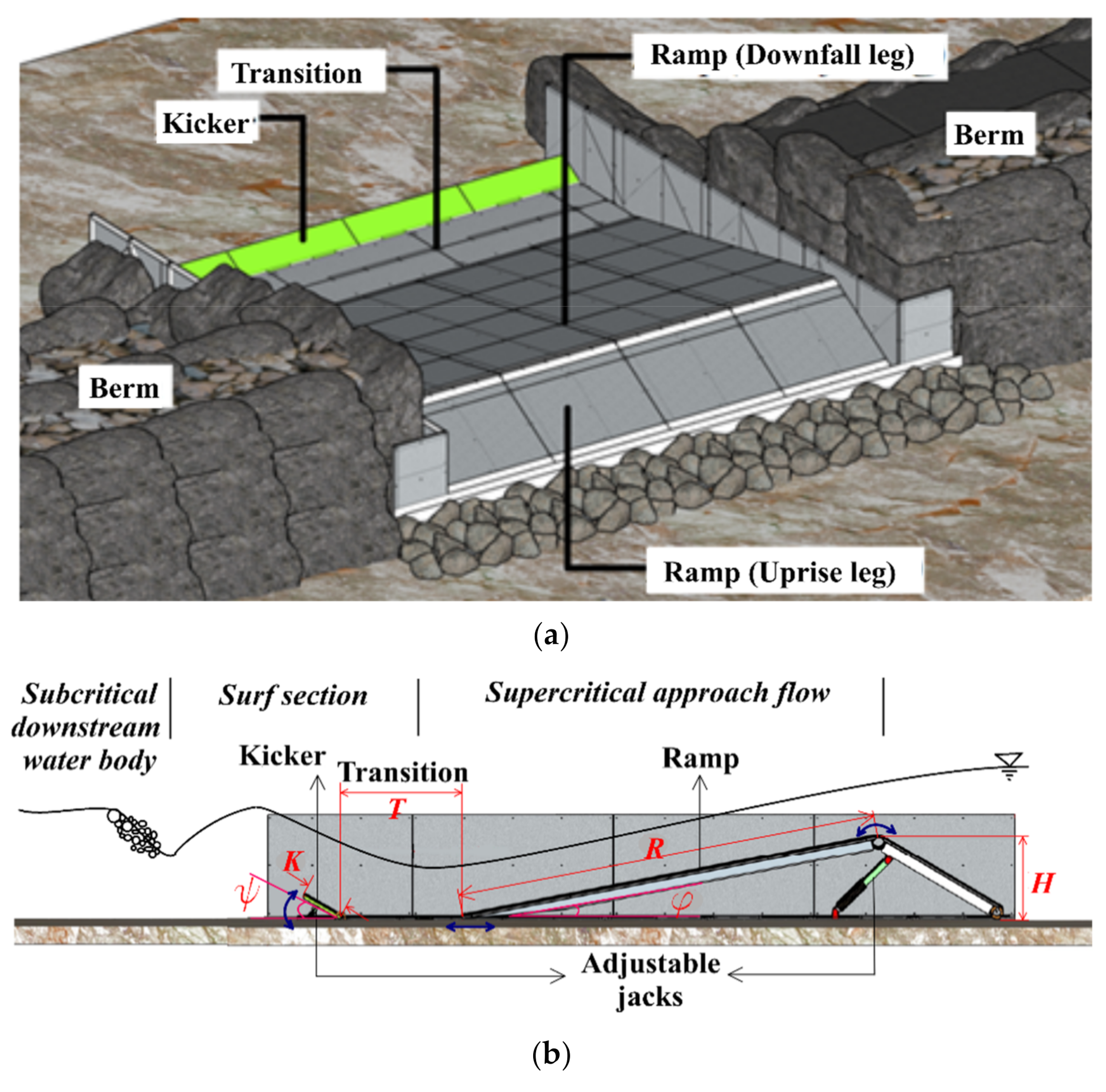
Figure 1. Structure under investigation: (a) perspective, (b) profile, (c) geometry of the numerical model (this does not show the full model extent to the upstream and downstream boundaries).
Water 13 01287 g001aWater 13 01287 g001b
Figure 2. Variation of the wave height versus grid size of the computational mesh. (flow per unit width of the ramp = 3.5 m2/s, tailwater depth = 0.86 m, ramp height = 1.0 m, Kicker length = 0.75 m, kicker angle = 25°).
Water 13 01287 g002
Figure 3. Transition from surf wave to broken wave (conventional hydraulic jump) by tailwater manipulation—photo courtesy of Wyl [33].
Water 13 01287 g003
Figure 4. Calibration of the numerical model with laboratory data: (a) physical versus numerical simulated wave (images are at the same scale—physical model photo courtesy of Koch [24]), (b) comparison of water surface profiles.
Water 13 01287 g004
Figure 5. Weir coefficient and relative depth for ramps of different steepness.
Water 13 01287 g005
Figure 6. Effect of the ramp profile on the surf wave: (a) effect of the ramp steepness on wave profile and velocity distribution, (b) sensitivity of the surf wave to ramp slope.
Water 13 01287 g006
Figure 7. Effect of the transition length on the surf wave: (a) required transition for complete development of the trough, (b) sensitivity of the surf wave to transition length.
Water 13 01287 g007
Figure 8. Sensitivity of the surf wave to tailwater depth at different flowrates: (a) effect of tailwater depth on wave profile, (b) tailwater depth, wave height and steepness versus flowrate.
Water 13 01287 g008
Figure 9. Effect of kicker length on wave profile.
Water 13 01287 g009
Figure 10. Flow field of river surf waves: (a) wave train in Ottawa river, (b) effect of kicker length on velocity field—cutaway view down the channel centerline.
Water 13 01287 g010
Figure 11. Wave adjustment by means of the kicker: (a) extremely long versus extremely steep kicker, (b) sensitivity of the extreme wave to reduction in tailwater depth, (c) extreme kickers of same height—longer versus steeper.
Water 13 01287 g011aWater 13 01287 g011b
Figure 12. Similarity of wave profiles for ramps of different height; (a) natural dimension water surface profiles, (b) scaled (dimensionless) water surface profiles.
Water 13 01287 g012
Figure 13. Comparing surf wave (with kicker) versus hydraulic jump (without kicker).
Water 13 01287 g013
Publisher’s Note: MDPI stays neutral with regard to jurisdictional claims in published maps and institutional affiliations.