Sloshing Motion in a Real-Scale Water Storage Tank under Nonlinear Ground Motion


Abstract
1. Introduction
2. Numerical Method and Model
2.1. Governing Equation
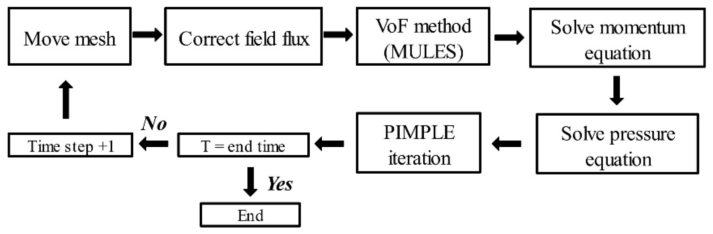
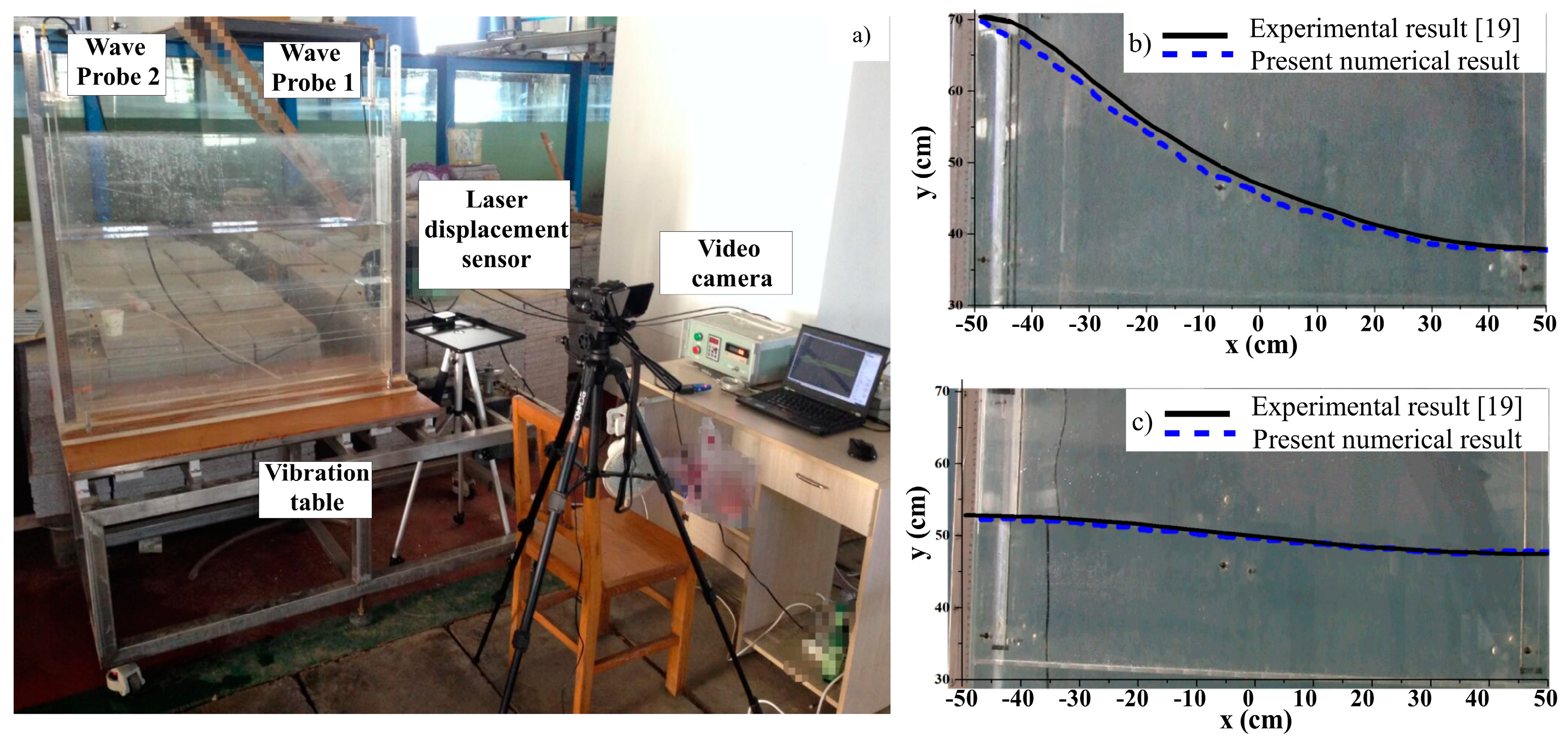
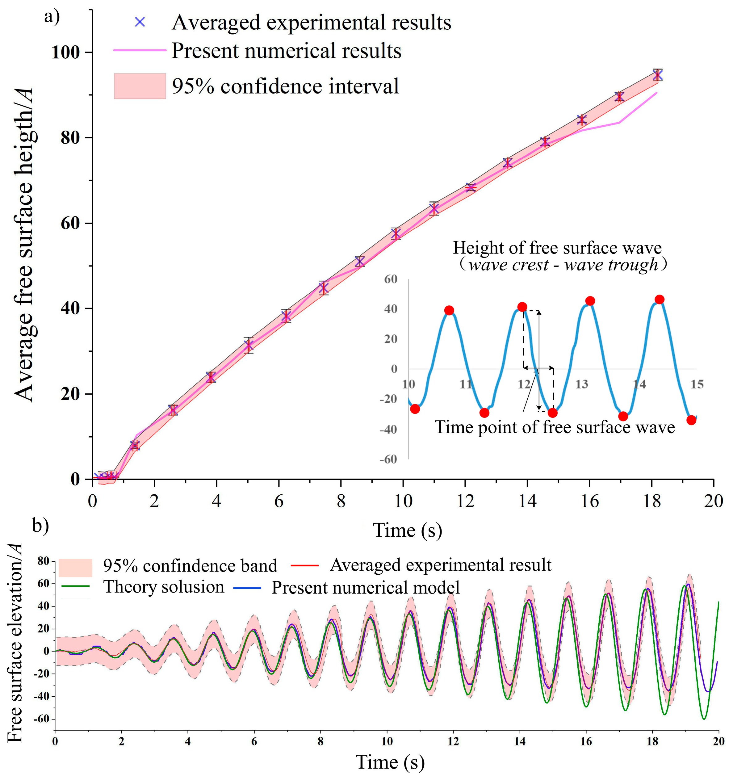
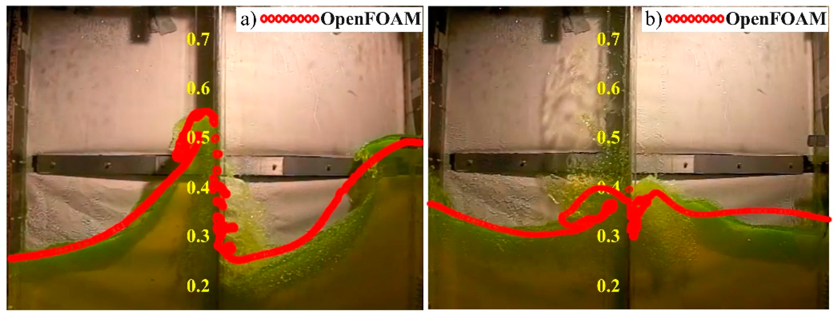
2.2. Numerical Model
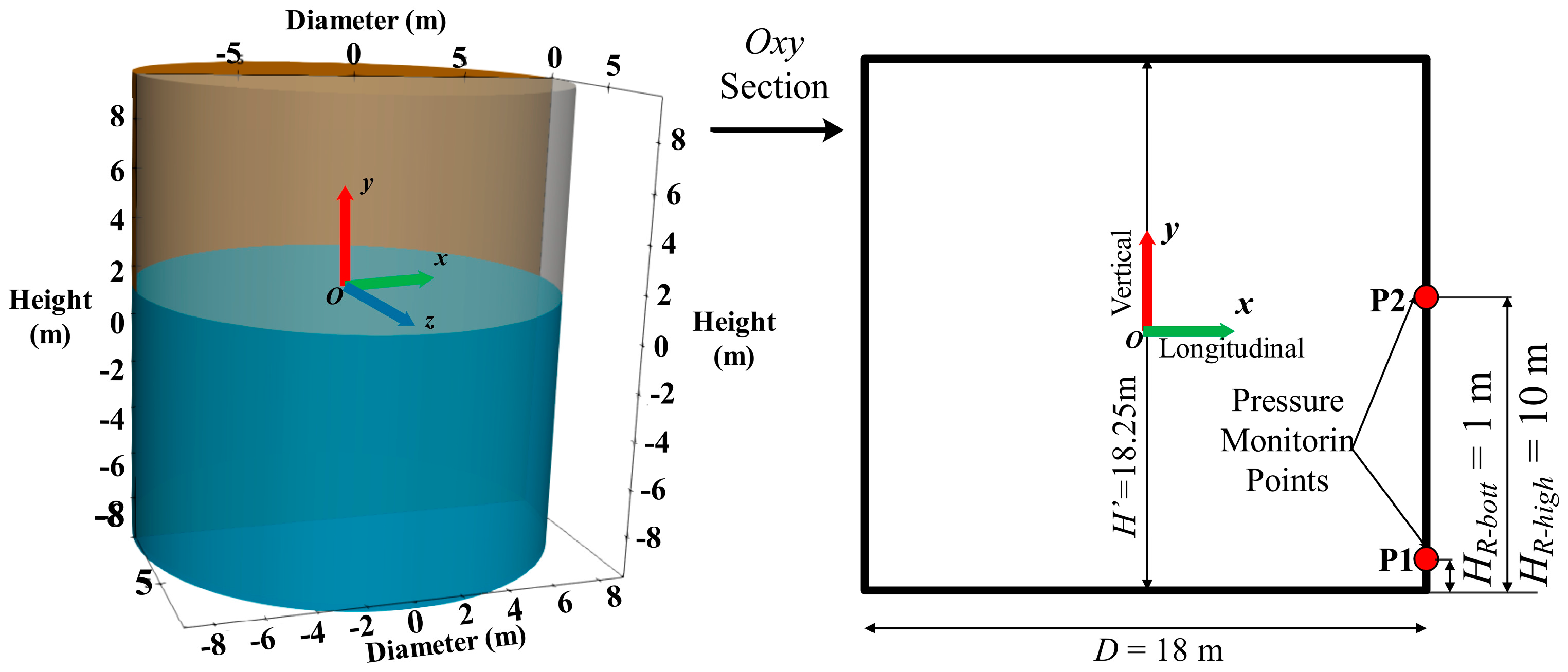
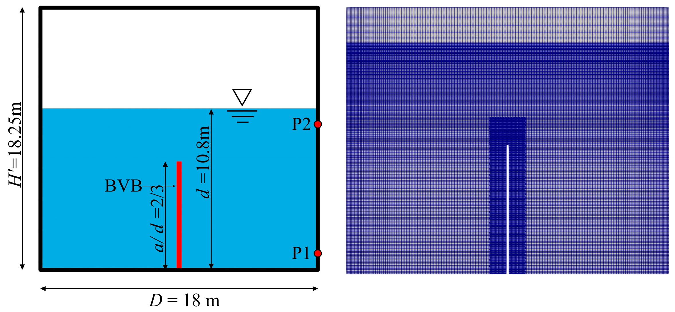
2.3. Problem Description
3. Results and Discussion
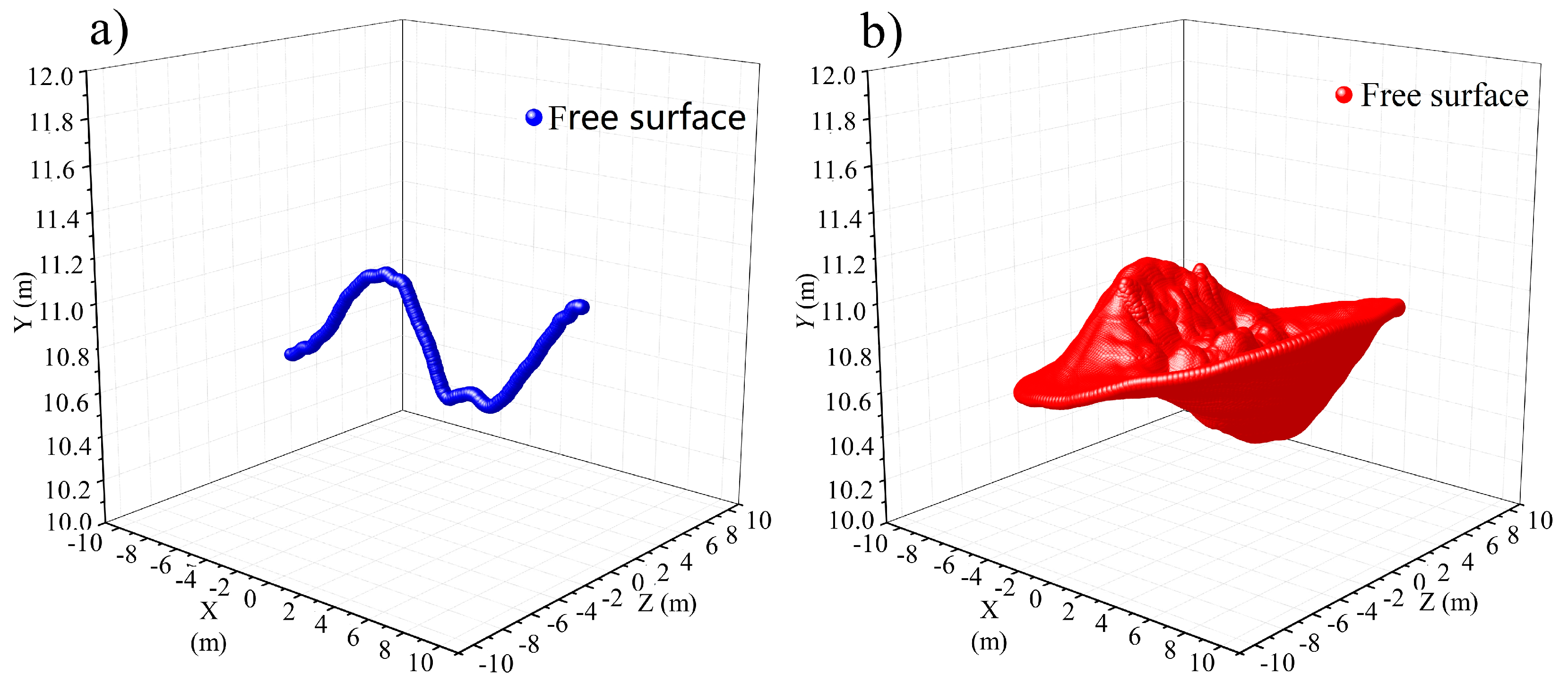
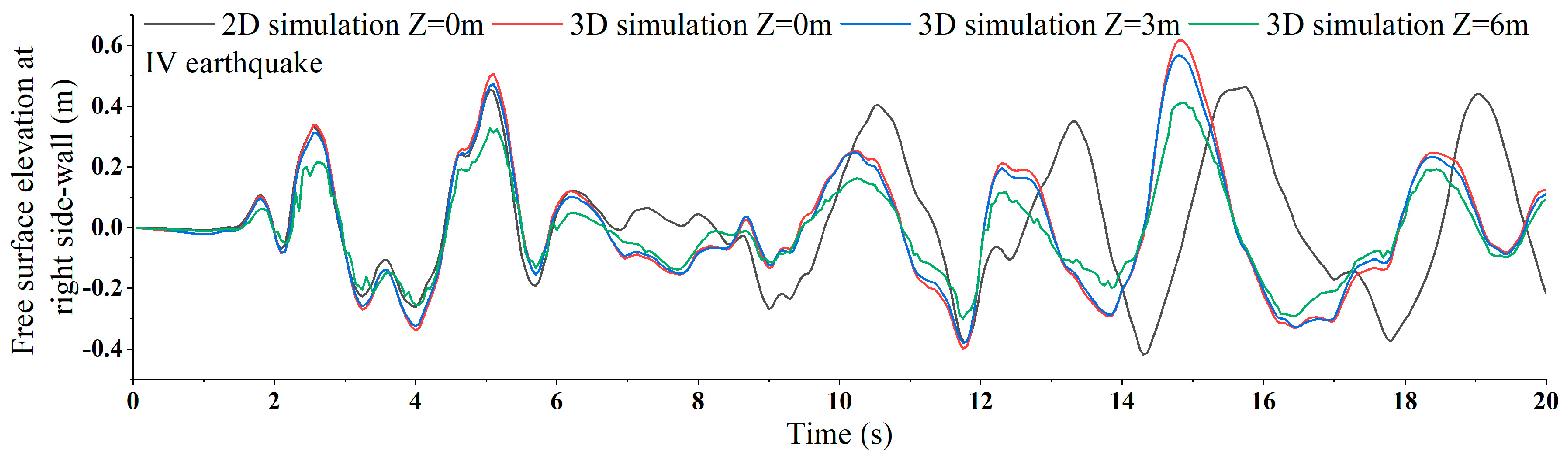
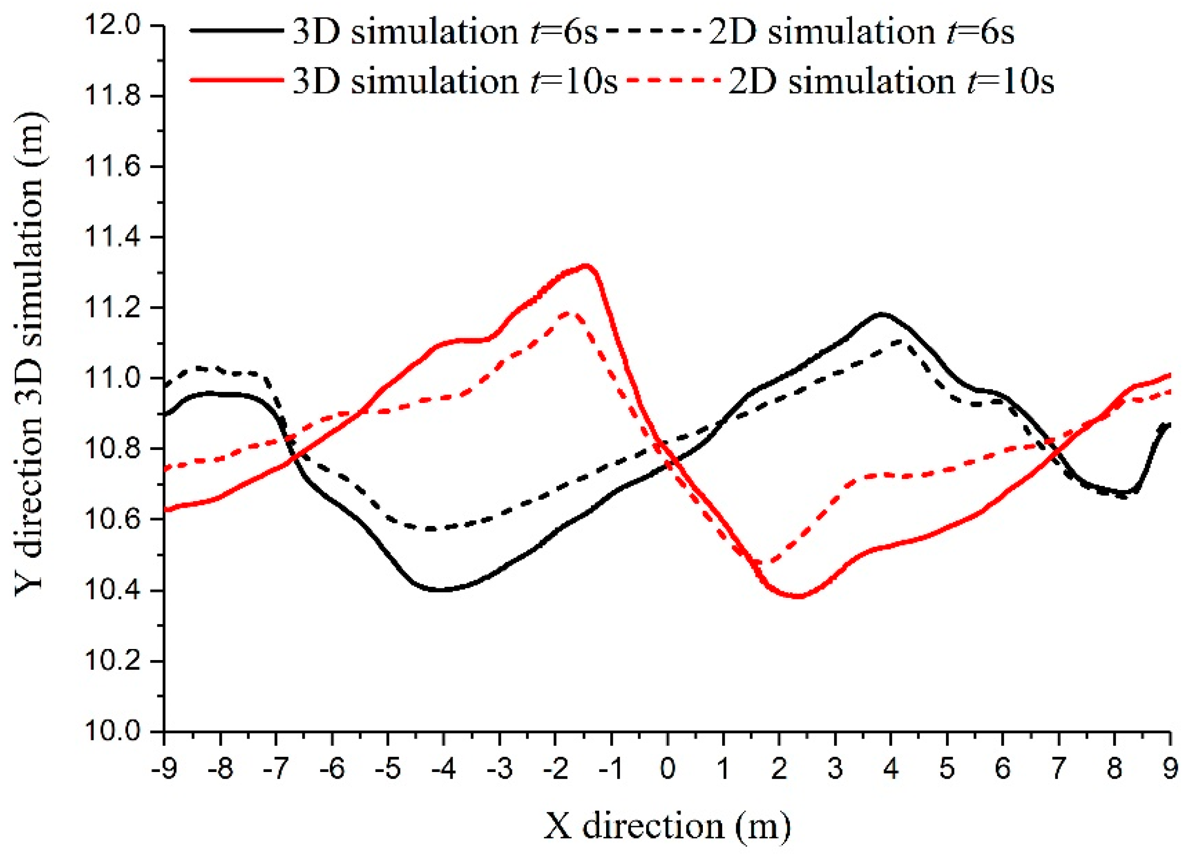
3.1. Comparison of Water Motion between Two-Dimensional and Three-Dimensional Results
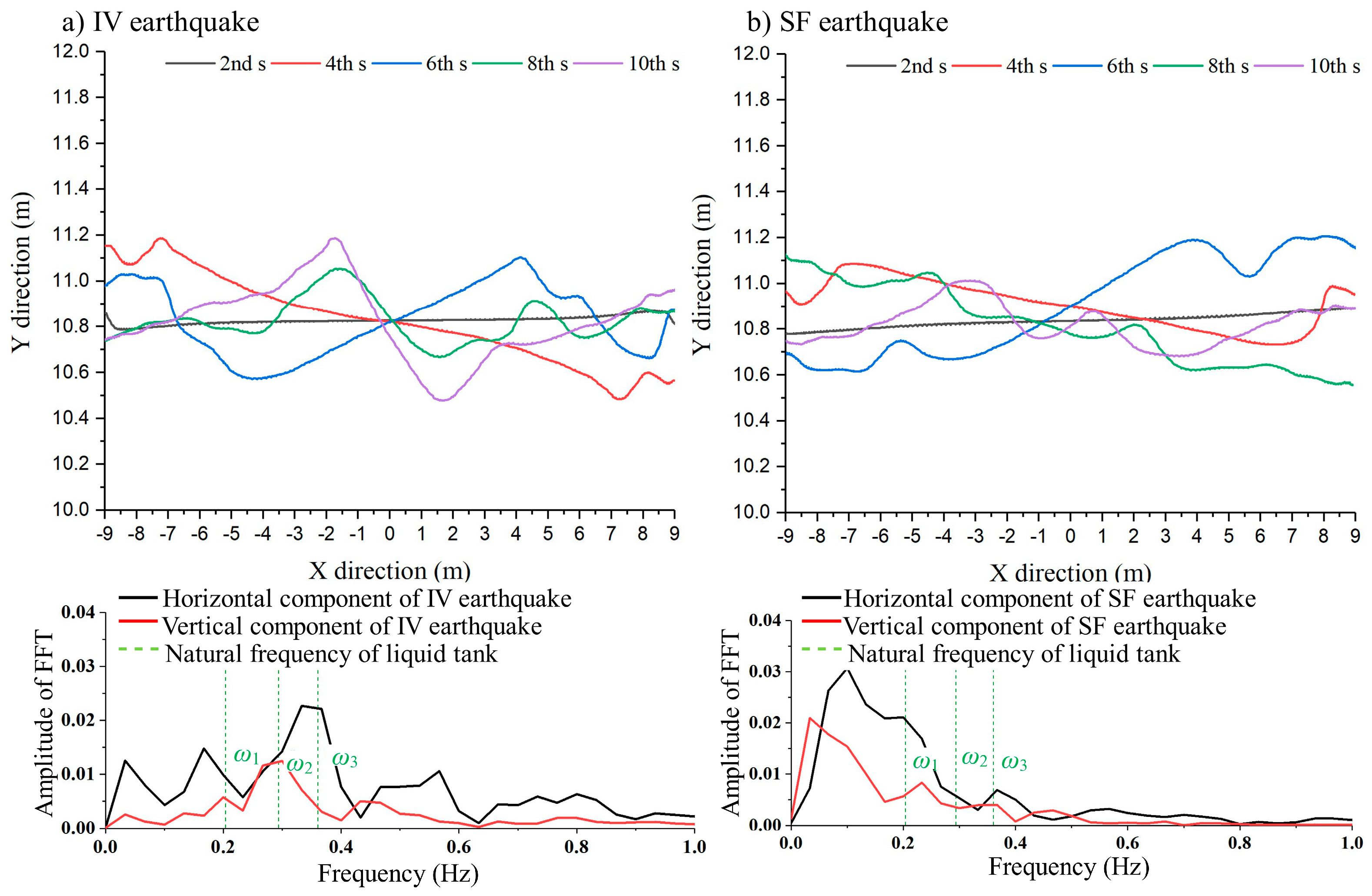
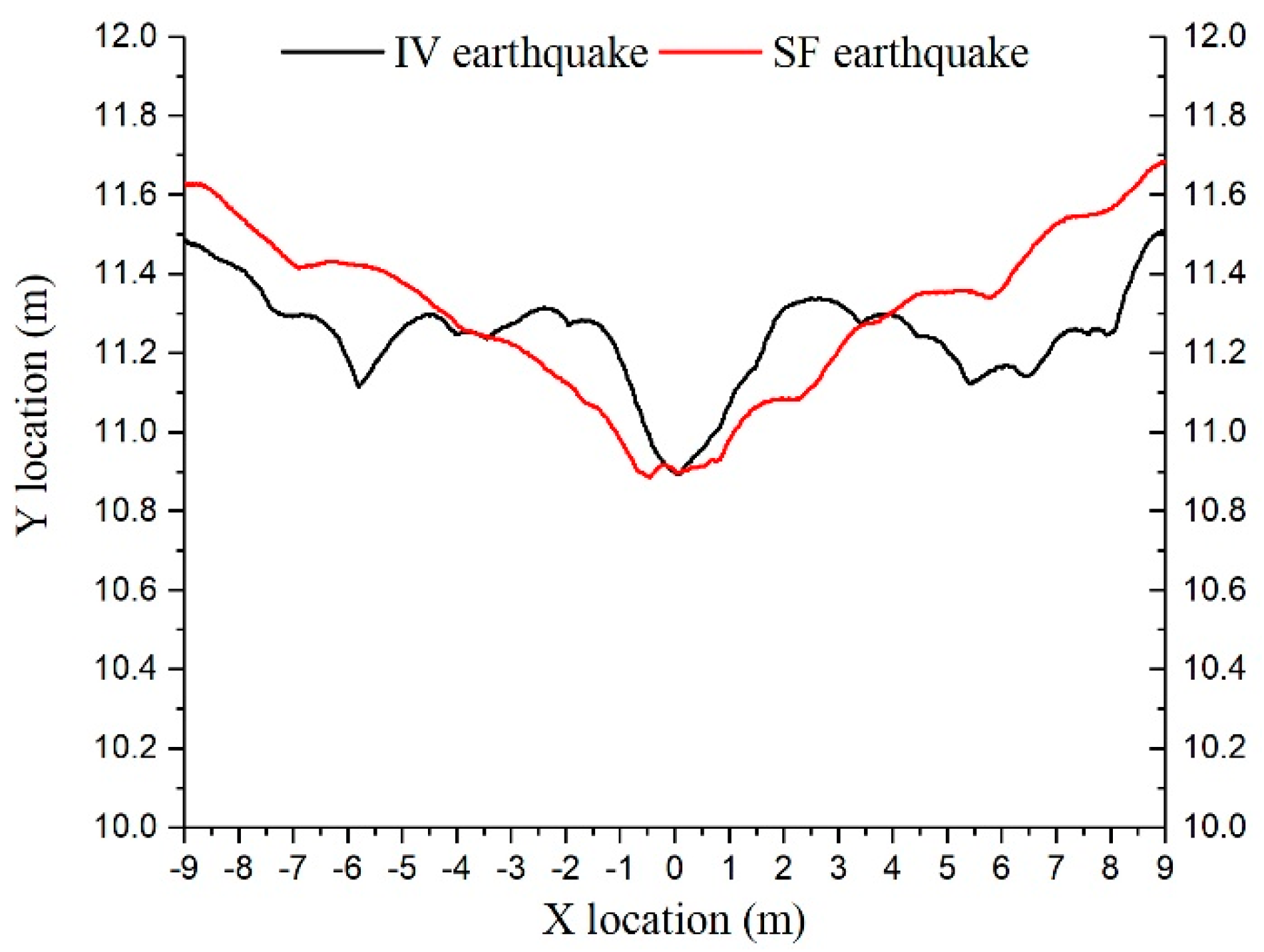
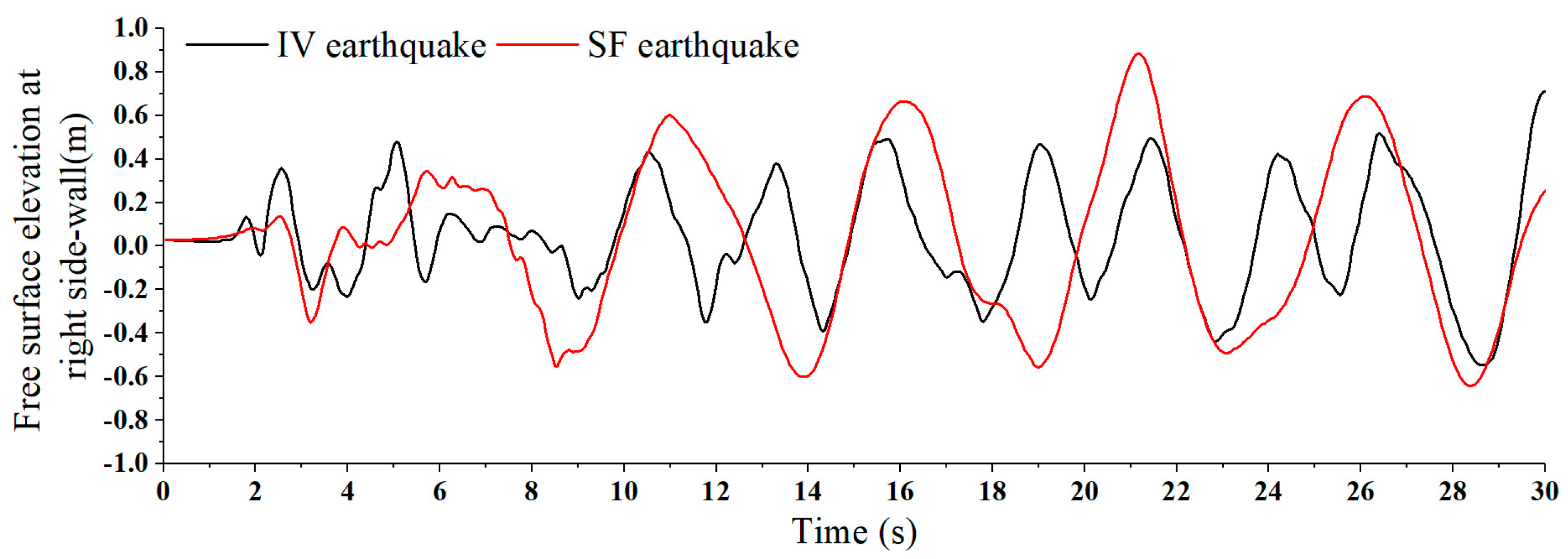
3.2. Free Surface Motion in the High Filling Depth Water Tank under Seismic Excitation
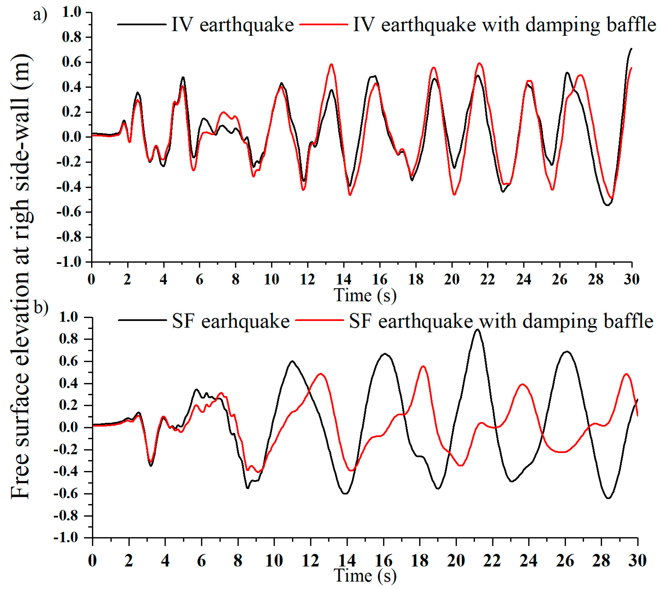
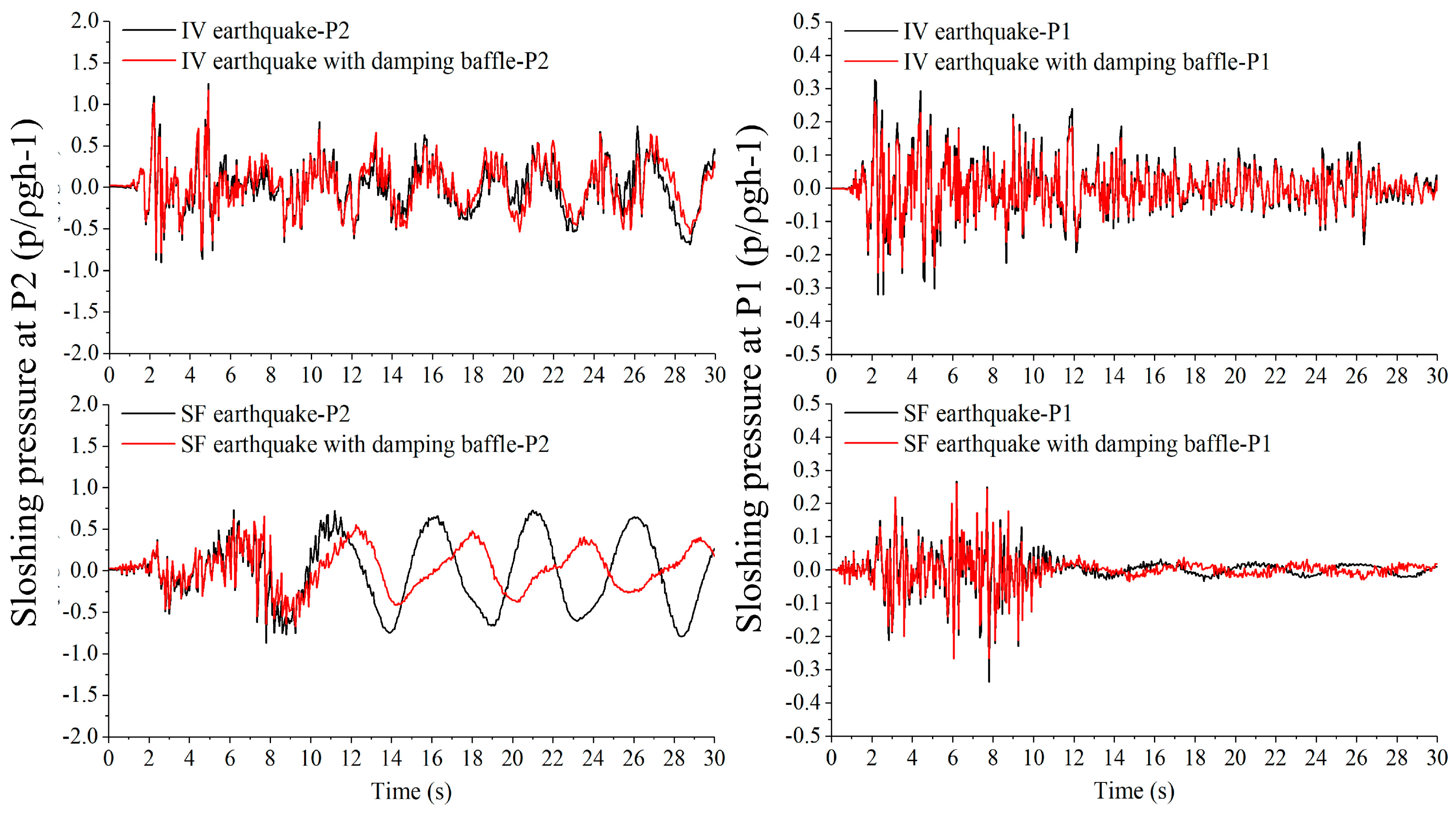
3.3. Seismic Design of the Water Storage Tank and the Anti-Sloshing Ability of the Damping Baffle
4. Conclusions
Author Contributions
Funding
Conflicts of Interest
References
- Soroushnia, S.; Tafreshi, S.T.; Omidinasab, F.; Beheshtian, N.; Soroushnia, S. Seismic performance of RC elevated water tanks with frame staging and exhibition damage pattern. Procedia Eng. 2011, 14, 3076–3087. [Google Scholar] [CrossRef]
- Korkmaz, K.A.; Sari, A.; Carhoglu, A.I. Seismic risk assessment of storage tanks in Turkish industrial facilities. J. Loss Prev. Process Ind. 2011, 24, 314–320. [Google Scholar] [CrossRef]
- Vakilaadsarabi, A.; Miyajima, M.; Murata, K. Study of the Sloshing of Water Reservoirs and Tanks due to Long Period and Long Duration Seismic Motions. In Proceedings of the 15th World Conference on Earthquake Engineering, Lisbon, Portugal, 24–28 September 2012; pp. 1–10. [Google Scholar]
- Zama, S.; Nishi, H.; Yamada, M.; Hatayama, K. Damage of Oil Storage Tanks Caused by Liquid Sloshing in the 2003 Tokachi Oki Earthquake and Revision of Design Spectra in the Long-Period Range. In Proceedings of the 14th World Conference on Earthquake Engineering, Beijing, China, 12–17 October 2008; pp. 1–8. [Google Scholar]
- Faltinsen, O.M.; Timokha, A.N. Sloshing; Cambridge University Press: Cambridge, UK, 2009. [Google Scholar]
- Frandsen, J.B. Sloshing motions in excited tanks. J. Comput. Phys. 2004, 196, 53–87. [Google Scholar] [CrossRef]
- Faltinsen, O.M.; Timokha, A.N. An adaptive multimodal approach to nonlinear sloshing in a rectangular tank. J. Fluid Mech. 2001, 432, 167–200. [Google Scholar] [CrossRef]
- Virella, J.C.; Prato, C.A.; Godoy, L.A. Linear and nonlinear 2D finite element analysis of sloshing modes and pressures in rectangular tanks subject to horizontal harmonic motions. J. Sound Vib. 2008, 312, 442–460. [Google Scholar] [CrossRef]
- Gavrilyuk, I.; Lukovsky, I.; Trotsenko, Y.; Timokha, A. Sloshing in a vertical circular cylindrical tank with an annular baffle. Part 1. Linear fundamental solutions. J. Eng. Math. 2006, 54, 71–88. [Google Scholar] [CrossRef]
- Chen, Y.; Xue, M.A. Numerical simulation of liquid sloshing with different filling levels using OpenFOAM and experimental validation. Water 2018, 10, 1752. [Google Scholar] [CrossRef]
- Akyldz, H.; Erdem Ünal, N.; Aksoy, H. An experimental investigation of the effects of the ring baffles on liquid sloshing in a rigid cylindrical tank. Ocean Eng. 2013, 59, 190–197. [Google Scholar] [CrossRef]
- Faltinsen, O.M.; Timokha, A.N. Analytically approximate natural sloshing modes for a spherical tank shape. J. Fluid Mech. 2012, 703, 391–401. [Google Scholar] [CrossRef][Green Version]
- Isaacson, M.; Premasiri, S. Hydrodynamic damping due to baffles in a rectangular tank. Can. J. Civ. Eng. 2001, 28, 608–616. [Google Scholar] [CrossRef]
- Biswal, K.C.; Bhattacharyya, S.K.; Sinha, P.K. Non-linear sloshing in partially liquid filled containers with baffles. Int. J. Numer. Methods Eng. 2006, 68, 317–337. [Google Scholar] [CrossRef]
- Faltinsen, O.M.; Firoozkoohi, R.; Timokha, A.N. Analytical modeling of liquid sloshing in a two-dimensional rectangular tank with a slat screen. J. Eng. Math. 2011, 70, 93–109. [Google Scholar] [CrossRef]
- Lee, D.H.; Kim, M.H.; Kwon, S.H.; Kim, J.W.; Lee, Y.B. A parametric sensitivity study on LNG tank sloshing loads by numerical simulations. Ocean Eng. 2007, 34, 3–9. [Google Scholar] [CrossRef]
- Jin, H.; Liu, Y.; Song, R.; Liu, Y. Analytical Study on the Effect of a Horizontal Perforated Plate on Sloshing Motion in a Rectangular Tank. J. Offshore Mech. Arct. Eng. 2020, 142. [Google Scholar] [CrossRef]
- Jin, H.; Liu, Y.; Li, H.; Fu, Q. Numerical analysis of the flow field in a sloshing tank with a horizontal perforated plate. J. Ocean Univ. China 2017, 16, 575–584. [Google Scholar] [CrossRef]
- Jin, H.; Liu, Y.; Li, H.J. Experimental study on sloshing in a tank with an inner horizontal perforated plate. Ocean Eng. 2014, 82, 75–84. [Google Scholar] [CrossRef]
- Xue, M.A.; Zheng, J.; Lin, P.; Yuan, X. Experimental study on vertical baffles of different configurations in suppressing sloshing pressure. Ocean Eng. 2017, 136, 178–189. [Google Scholar] [CrossRef]
- Chen, W.; Haroun, M.A.; Liu, F. Large amplitude liquid sloshing in seismically excited tanks. Earthq. Eng. Struct. Dyn. 1996, 25, 653–669. [Google Scholar] [CrossRef]
- Huerta-Lopez, C.I.; Shin, Y.; Powers, E.J.; Roesset, J.M. Time-frequency analysis of earthquake records. In Proceedings of the 12th World Conference on Earthquake Engineering, Auckland, New Zealand, 30 January–4 February 2000; pp. 1–8. [Google Scholar]
- Chen, Y.-H.; Hwang, W.-S.; Ko, C.-H. Sloshing behaviours of rectangular and cylindrical liquid tanks subjected to harmonic and seismic excitations. Earthq. Eng. Struct. Dyn. 2007, 36, 1701–1717. [Google Scholar] [CrossRef]
- Xue, M.; Chen, Y.; Yuan, X.; Dou, P. A Study on Effects of the Baffles in Reducing Sloshing in a Container under Earthquake Excitation. In Proceedings of the Twenty-ninth (2019) International Ocean and Polar Engineering Conference, Hawaii, HI, USA, 16–21 June 2019; pp. 3393–3397. [Google Scholar]
- Faltinsen, O.M.; Timokha, A.N. Asymptotic modal approximation of nonlinear resonant sloshing in a rectangular tank with small fluid depth. J. Fluid Mech. 2002, 470, 319–357. [Google Scholar] [CrossRef]
- Ockendon, H.; Ockendon, J.R.; Johnson, A.D. Resonant sloshing in shallow water. J. Fluid Mech. 1986, 167, 465–479. [Google Scholar] [CrossRef]
- Bouscasse, B.; Antuono, M.; Colagrossi, A.; Lugni, C. Numerical and experimental investigation of nonlinear shallow water sloshing. Int. J. Nonlinear Sci. Numer. Simul. 2013, 14, 123–138. [Google Scholar] [CrossRef]
- Waterhouse, D.D. Resonant Sloshing Near a Critical Depth. J. Fluid Mech. 1994, 281, 313–318. [Google Scholar] [CrossRef]
- Rognebakke, O.F.; Faltinsen, O.M. Sloshing induced impact with air cavity in rectangular tank with a high filling ratio. In Proceedings of the 20th International Workshop on Water Waves and Floating Bodies, Spitsbergen, Norway, 29 May–1 June 2005. [Google Scholar]
- Jasak, H.; Jemcov, A.; Tukovic, Z. OpenFOAM: A C++ library for complex physics simulations. In Proceedings of the International Workshop on Coupled Methods in Numerical Dynamics, Dubrovnik, Croatia, 19–21 September 2007; pp. 1–20. [Google Scholar]
- Liu, D.; Tang, W.; Wang, J.; Xue, H.; Wang, K. Comparison of laminar model, RANS, LES and VLES for simulation of liquid sloshing. Appl. Ocean Res. 2016, 59, 638–649. [Google Scholar] [CrossRef]
- Faltinsen, O.M. A numerical nonlinear method of sloshing in tanks with two-dimensional flow. J. Ship Res. 1978, 22, 193–202. [Google Scholar]
- Faltinsen, O.M.; Firoozkoohi, R.; Timokha, A.N. Steady-state liquid sloshing in a rectangular tank with a slat-type screen in the middle: Quasilinear modal analysis and experiments. Phys. Fluids 2011, 23. [Google Scholar] [CrossRef]
- Haroun, M.A. Vibration studies and tests of liquid storage tanks. Earthq. Eng. Struct. Dyn. 1983, 11, 179–206. [Google Scholar] [CrossRef]
- Jones, L.M.; Hauksson, E. Evaluation of Earthquake Potential in Southern California. In Proceedings of the Future directions in evaluating earthquake hazards of southern California, Los Angeles, CA, USA, 12–13 November 1985; pp. 63–72. [Google Scholar]
- Goudarzi, M.A.; Sabbagh-Yazdi, S.R. Analytical and experimental evaluation on the effectiveness of upper mounted baffles with respect to commonly used baffles. Ocean Eng. 2012, 42, 205–217. [Google Scholar] [CrossRef]
- Faltinsen, O.M. Sloshing. Adv. Mech. 2017, 47, 1–24. [Google Scholar] [CrossRef]
- Ancheta, T.D.; Darragh, R.B.; Stewart, J.P.; Seyhan, E.; Silva, W.J.; Chiou, B.S.J.; Wooddell, K.E.; Graves, R.W.; Kottke, A.R.; Boore, D.M.; et al. NGA-West2 database. Earthq. Spectra 2014, 30, 989–1005. [Google Scholar] [CrossRef]
- Sanapala, V.S.; Rajkumar, M.; Velusamy, K.; Patnaik, B.S.V. Numerical simulation of parametric liquid sloshing in a horizontally baffled rectangular container. J. Fluids Struct. 2018, 76, 229–250. [Google Scholar] [CrossRef]
- Demirel, E.; Aral, M. Liquid Sloshing Damping in an Accelerated Tank Using a Novel Slot-Baffle Design. Water 2018, 10, 1565. [Google Scholar] [CrossRef]
- Dinçer, A.E. Investigation of the sloshing behavior due to seismic excitations considering two-way coupling of the fluid and the structure. Water 2019, 11, 2664. [Google Scholar] [CrossRef]


| Mesh | Description | Maximum Size (x × y) | Calculation Time (s) | Averaged Free Surface Peaks at Right Side Wall (x = 9 m) | Relative Difference |
|---|---|---|---|---|---|
| 1 | Fine | 0.075 × 0.025 | 3391 | 0.1839 m | - |
| 2 | Medium (used) | 0.15 × 0.05 | 464 | 0.1746 m | 5% |
| 3 | Coarse | 0.3 × 0.1 | 88 | 0.1580 m | 14% |
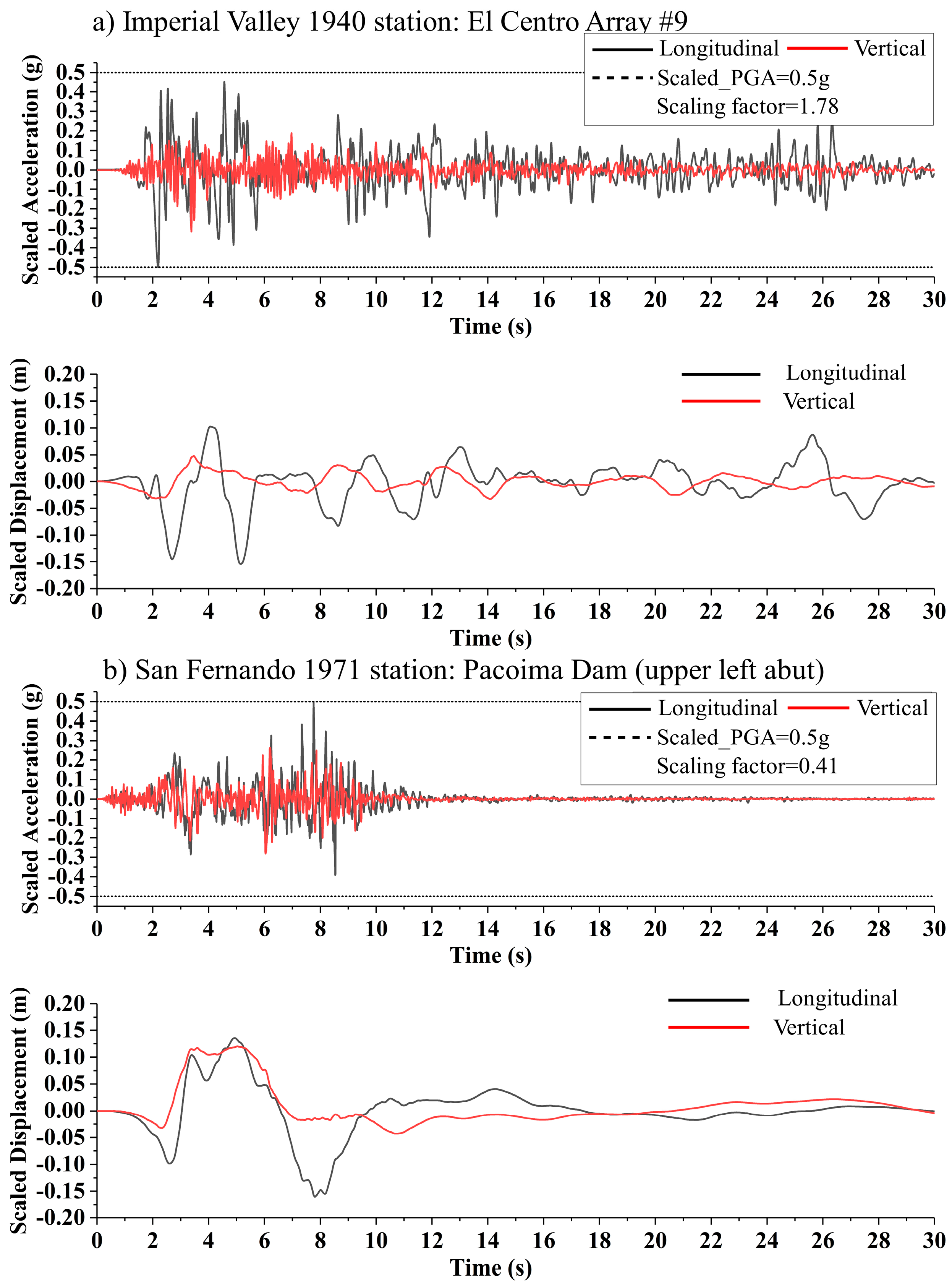
| Earthquake Event | Scaled PGA (g) | Scale Factor | Scaled PGD* (m) | Strong Motion Duration (s) |
|---|---|---|---|---|
| IV | Longitudinal: 0.5 Vertical: 0.317 | 1.78 | Longitudinal: 0.154 Vertical: 0.048 | 30 |
| SF | Longitudinal: 0.5 Vertical: 0.282 | 0.41 | Longitudinal: 0.160 Vertical: 0.120 | 18 |
© 2020 by the authors. Licensee MDPI, Basel, Switzerland. This article is an open access article distributed under the terms and conditions of the Creative Commons Attribution (CC BY) license (http://creativecommons.org/licenses/by/4.0/).
Share and Cite
Jin, H.; Song, R.; Liu, Y. Sloshing Motion in a Real-Scale Water Storage Tank under Nonlinear Ground Motion. Water 2020, 12, 2098. https://doi.org/10.3390/w12082098
Jin H, Song R, Liu Y. Sloshing Motion in a Real-Scale Water Storage Tank under Nonlinear Ground Motion. Water. 2020; 12(8):2098. https://doi.org/10.3390/w12082098
Chicago/Turabian StyleJin, Heng, Ruiyin Song, and Yi Liu. 2020. "Sloshing Motion in a Real-Scale Water Storage Tank under Nonlinear Ground Motion" Water 12, no. 8: 2098. https://doi.org/10.3390/w12082098
APA StyleJin, H., Song, R., & Liu, Y. (2020). Sloshing Motion in a Real-Scale Water Storage Tank under Nonlinear Ground Motion. Water, 12(8), 2098. https://doi.org/10.3390/w12082098