1. Introduction
The processes of managing and monitoring complex water distribution networks are often based on the design of district metered areas (DMAs) [
1,
2,
3,
4,
5,
6,
7], which allow for easier system monitoring and leakage identification [
8]. In the partitioning of networks into DMAs, pressure-reducing valves (PRVs), or devices capable of regulating the pressure downstream of the installation site, are often used [
9,
10,
11,
12]. Indeed, controlling pressures in the district allows limiting the water losses in the system itself [
13,
14,
15,
16,
17].
Among the different types of pressure-reducing valves, the most common are diaphragm valves, in which the pressure-regulating device operates in a direction transverse to the flow. Another type of pressure regulating valves, even though less frequently used, is piston-actuated valves, in which the regulating device operates in a direction parallel to the flow. The pilot that regulates the downstream pressure control mechanism can be mechanical or remotely electronically controlled, even in a real-time mode.
In the literature, diaphragm pressure-reducing valves have been extensively investigated, from device modelling, possibly in combination with an electronic control apparatus [
18,
19,
20,
21,
22,
23,
24] also under transient regimes [
25], to the optimisation of their location in networks and their setting value [
26,
27,
28,
29,
30,
31,
32,
33,
34,
35,
36,
37]. The efficiency of the use of PRVs in reducing losses has been demonstrated in several studies [
13,
14,
16,
17,
38].
However, the physical behaviour of PRVs has been investigated by only a limited number of studies. In particular, very few studies (e.g., [
23]) focused the attention on static and dynamic models of a PRV, as done more extensively for other types of valves like pressure relief valves [
39,
40], whereas some other studies focused on laboratory tests and analysis of the PRV behaviour. Within this latter case, Meniconi et al. [
41] characterised the behaviour of a diaphragm PRV through laboratory tests, both under steady and unsteady flow conditions, demonstrating the versatility of the device as an effective tool for pressure management. The same authors observed that pressure oscillations due to PRV adjustment manoeuvres are of short duration and do not result in any particular upstream propagations [
42]. Furthermore, the same authors [
43] observed that the PRV tends to act as a discontinuity in the presence of a pressure transient, splitting the system into two parts, and preventing any disturbances or pressure oscillations generated downstream of the valve from propagating upstream of the valve itself.
Other studies have instead highlighted some problems relating to the singular behaviours of these devices, an issue that also concerns different types of control valves [
44]. More specifically, some recent studies have shown the occurrence of instability in electronically controlled diaphragm PRVs under low-flow regimes. In particular, starting from field measurements, Ulanicki and Skworcow [
45] observed an unstable behaviour of PRVs below certain flow rates. Drawing on the latter study and through numerical simulations, Janus and Ulanicki [
19] showed that in the presence of a small randomly variable flow rate, the electronically controlled diaphragm PRV cannot maintain the pressure set-point, resulting in pressure oscillations around the set-point itself. In the context of fault detection and diagnosis with respect to diaphragm PRVs in water distribution networks, Changklom and Stoianov [
46] similarly identify possible anomalous behaviours of these devices that can lead to malfunctions and failures. It is worth stressing that the aforementioned studies mainly refer to diaphragm PRVs and, to authors’ knowledge, no study on the hydraulic application of a piston-actuated PRV is currently available.
Moving from these considerations, this paper is aimed at characterising the behaviour of a piston-actuated PRV (hereinafter labelled as PA-PRV) with a mechanical pilot. In particular, like other studies on diaphragm PRVs which are focused on valve field behaviour rather than on its static and dynamic modelling, the analysis are developed through laboratory tests by installing the PA-PRV in a hydraulic testbed and subjecting it to low-flow regimes, a condition consistent with the normal operating conditions of real small networks or DMAs. In fact, the analyses are carried out by means of laboratory tests, in which the PA-PRV is subjected to both pre-established flow rates and historical flow rates observed at the inlet section of a small DMA. The main characteristics of the pressure reduction valve and the testbed are given below and the tests carried out are then described. The results obtained are analysed and compared with those reported in other studies and, finally, some concluding remarks are given.
2. Materials and Methods
2.1. The PA-PRV and the Testbed
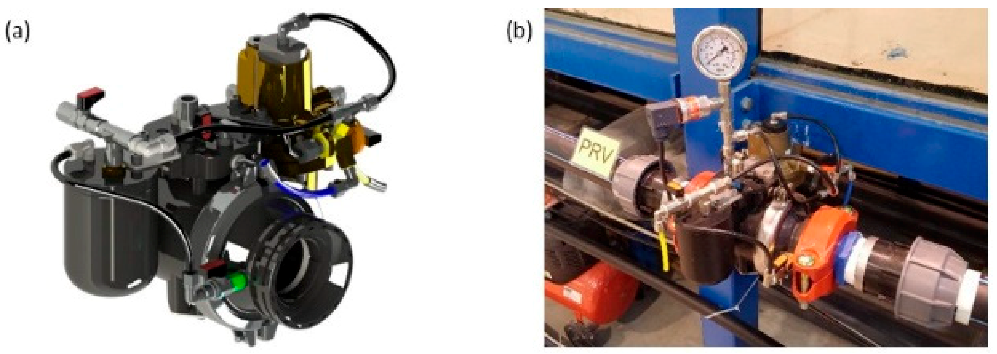
The PA-PRV analysed in this study (
Figure 1a,b) consists of a plastic valve and an independent control unit made up of a pilot and a three-position selector of the C-valve type marketed by Saisanket Ltd [
47].
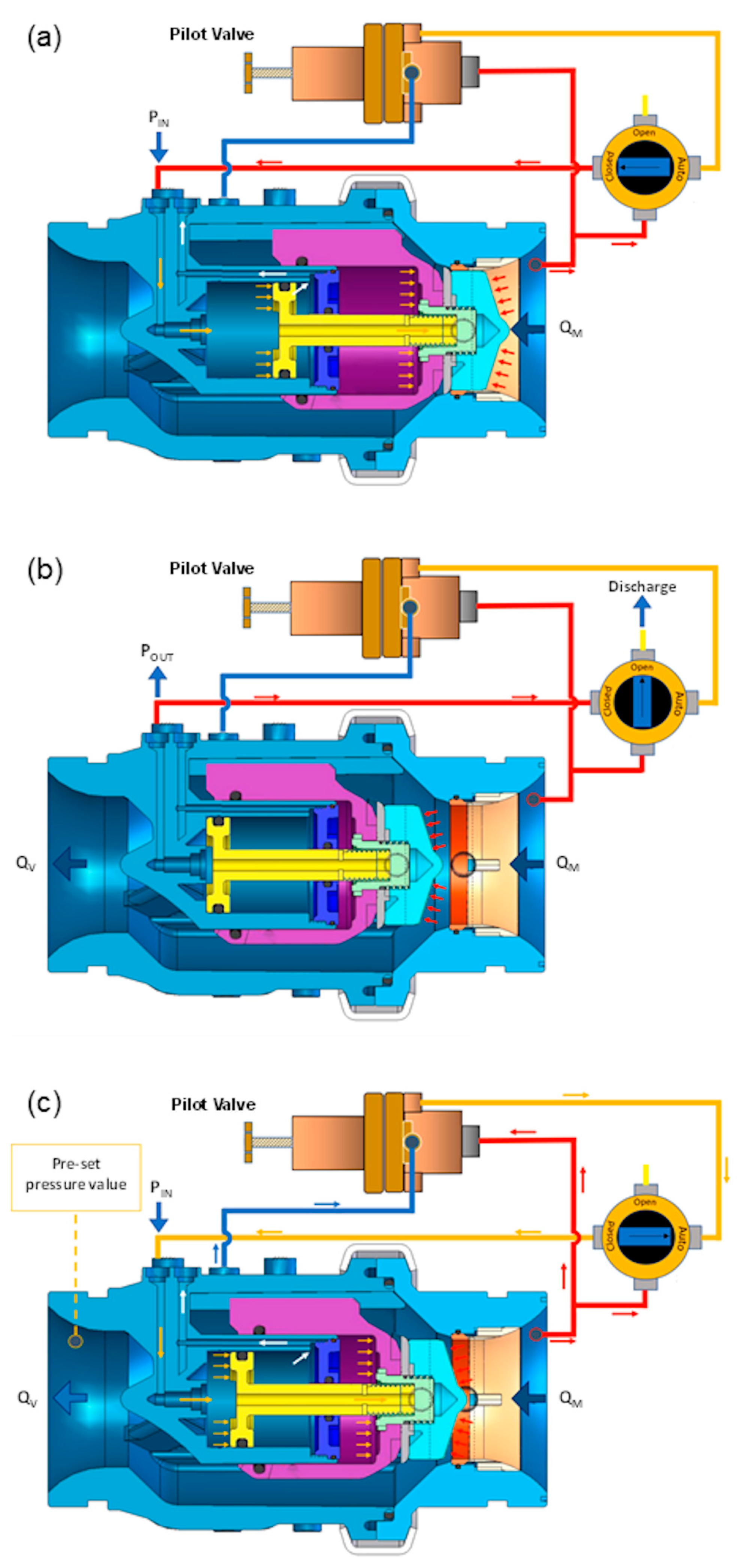
The three-way pilot controls the valve and in particular the movement of the piston, which in turn controls the pressure downstream of the valve. The piston is part of the double-chambered and bidirectional actuator system. The main closed control chamber and the secondary closing control chamber remain isolated from the valve’s flow (see
Figure 2).
In greater detail, the operating principle of the device is based on a balance of forces that is generated between the head of the piston and the pressure in the control chambers behind the piston itself. The force required to move the piston is derived from the high pressure upstream of the valve modulated by the pilot and then applied inside the closed control chamber. The ratio between the inner hydraulic surface area of the chamber and the external surface area allows the piston to move back and forth, providing a drive which enables the actuator to adjust to the required position, thus maintaining the pre-set parameter of downstream pressure (hereinafter, set-point). Control is applied by venting or supplying fluid to the closed control chamber (modulating functioning, see
Figure 2c). In the closure position (
Figure 2a), upstream pressure applied to the closing control chamber, on both front and back piston, creates a superior closing force overcoming upstream pressure applied to the actuator, thus closing the valve. In order to reach the opening position (
Figure 2b), the closing control chamber is vented while upstream pressure applied to the actuator creates a force that opens the valve.
The functioning of the device is based on the proprietary technology “Linear Flow Linear Control (LFLC)” which replaces a manual system that regulates the piston speed adjustment. This technology is based on the double-chambered actuator system which produces a soft closure, theoretically capable of preventing the occurrence of potentially dangerous pressure transients in the system. From an operational standpoint, the closed control chamber is directly connected to the pilot valve while the closing control chamber is completely filled with air in direct contact with the atmosphere through a specific hole on the valve body. The adjustment speed of the piston depends on the speed at which the air enters or leaves the secondary control chamber. The valve has a "Normally Open" function, which ensures that the valve will remain open in the event of pilot anomalies and, according to the manufacturer, the time required for the full stroke closure or opening of the PA-PRV results between 0.8 and 3.7 s [
47].
The PA-PRV considered has a nominal diameter DN of 50 mm. The operational range of the valve indicated by the manufacturer is between 0 and 25 bar and between 0 and 80 m³/h and the tolerance with respect to the set value of the downstream pressure is ±0.05 bar.
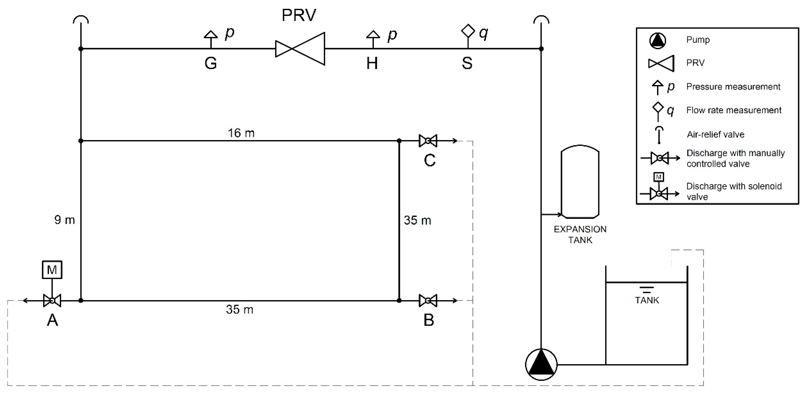
The behaviour of the PA-PRV was investigated through a set of laboratory tests performed using the hydraulic system located in the Hydraulic Laboratory of the Engineering Department of the University of Ferrara, the layout of which is illustrated in
Figure 3.
The closed hydraulic system is fed from a tank with a capacity of 0.9 m3 by a centrifugal pump which provides, at the best efficiency point, a flow rate of approximately 1 L/s and a head of 52 m. An electronic pressure switch and an expansion vessel are installed to protect the pumping system against dry-running and pressure fluctuations in the network, respectively.
The supply pipe consists of a polyethylene pipe with a diameter of 63 mm (PN 16) and a length of approximately 10 m, along which the PA-PRV, two pressure measurement sections, upstream and downstream of the PA-PRV (respectively, sections H and G in
Figure 3), and an electromagnetic flowmeter (section S in
Figure 3) are installed. The supply pipe is connected to a polyethylene loop with a diameter of 40 mm (PN 10) for a total length of 100 m and characterised by the presence of three junctions where the discharge can be released towards the tank through a solenoid valve, indicated with the letter A in
Figure 3 and two ball valves indicated with the letters B and C in
Figure 3.
The degree of opening of the three valves located at sections A, B and C allows the discharge flowing out from the loop towards the tank to be modulated and, consequently, makes it possible to control the discharge in the supply pipe flowing through the PA-PRV. In particular, the solenoid valve installed at manoeuvring section A is characterised by a remotely controlled modular opening, while the ball valves at sections B and C are manually controlled. The polyethylene loop and the three sections (A, B and C) basically represent a simple loop of a water distribution network with the associated water utility connections. From an operational standpoint, the flow from each of the three sections A, B and C is discharged into the supply tank, thus closing the hydraulic circuit.
During the experimental tests, the flow rate and the pressure at strategic sections of the system were monitored; in particular, the following instruments were installed: 1 electromagnetic flowmeter (DN 50) which outputs an electric current signal (4 to 20 mA) at section S, and 3 membrane pressure transducers which output a voltage signal (0 to 10 V), upstream and downstream of the PRV, at sections H and G, respectively, and at manoeuvring section A.
The simultaneous sampling of the pressure and flow rate was performed at a frequency of 100 Hz through a series of modules designed to convert the analogue signals into digital data; the acquisition was managed with the programming software LabView®.
2.2. Laboratory Tests
The characterisation of the PA-PRV was conducted through a set of laboratory tests aimed at verifying the ability of the PA-PRV to maintain an imposed set-point at the downstream section with respect to different flow rates. The laboratory tests can be schematically divided into two phases. In a first phase, the system was subjected to a rapid flow rate variation ∆Q starting from a pre-established initial flow rate Qin. In particular, tests were carried out by imposing the same flow rate variation ∆Q and considering different values of the initial flow rate Qin. During the second phase, the behaviour of the PA-PRV was analysed by subjecting the system to a series of flow rates historically observed at the inlet section of a small DMA. In both cases the set-point imposed was equal to 2.4 bar.
During the first phase, the behaviour of the PA-PRV was analysed in relation to a flow rate variation ∆Q within the system equal to 0.5 L/s starting from different values of the initial flow rate Q
in. In particular, nine initial flow rates Q
in with values between 1.4 and 0.6 L/s, with a step of 0.1 L/s, and corresponding final flow rates Q
fin between 0.9 and 0.1 L/s, were considered. The initial flow rate Q
in characterising each test was obtained by fixing a certain modulation of the valves at sections A and B through a trial and error procedure (see
Table 1) while the valve at section C was systematically closed. On the other hand, the final flow rate Q
fin at the end of each test was obtained through a complete closure of the ball valve located at section B.
Summarizing, the degree of opening of the valves A and B were determined by trial and error so that they would determine an initial flow rate in the system equal to Qin and a final flow rate equal to Qfin following the complete closure of the ball valve located at section B. In order to evaluate the variability of the behaviour of the PA-PRV with respect to the same boundary conditions, each test was repeated five times and for each test the sampling of the pressure and flow rate was carried out for a duration of 6 min, 1 min before and 5 min after the flow rate reduction manoeuvre.
The second phase of testing was aimed at the validation of the results obtained and consisted of an analysis of the PA-PRV based on a real-time series of flow rates. In particular, a 1 min time step time series of flow rates observed at the inlet section of a district was imposed within the laboratory system in order to show that the first phase test conditions can be found in ordinary operational conditions of real DMAs. The data gathered for this purpose refer to the water distribution network of Gorino Ferrarese (Ferrara, Italy), which serves approximately 300 users [
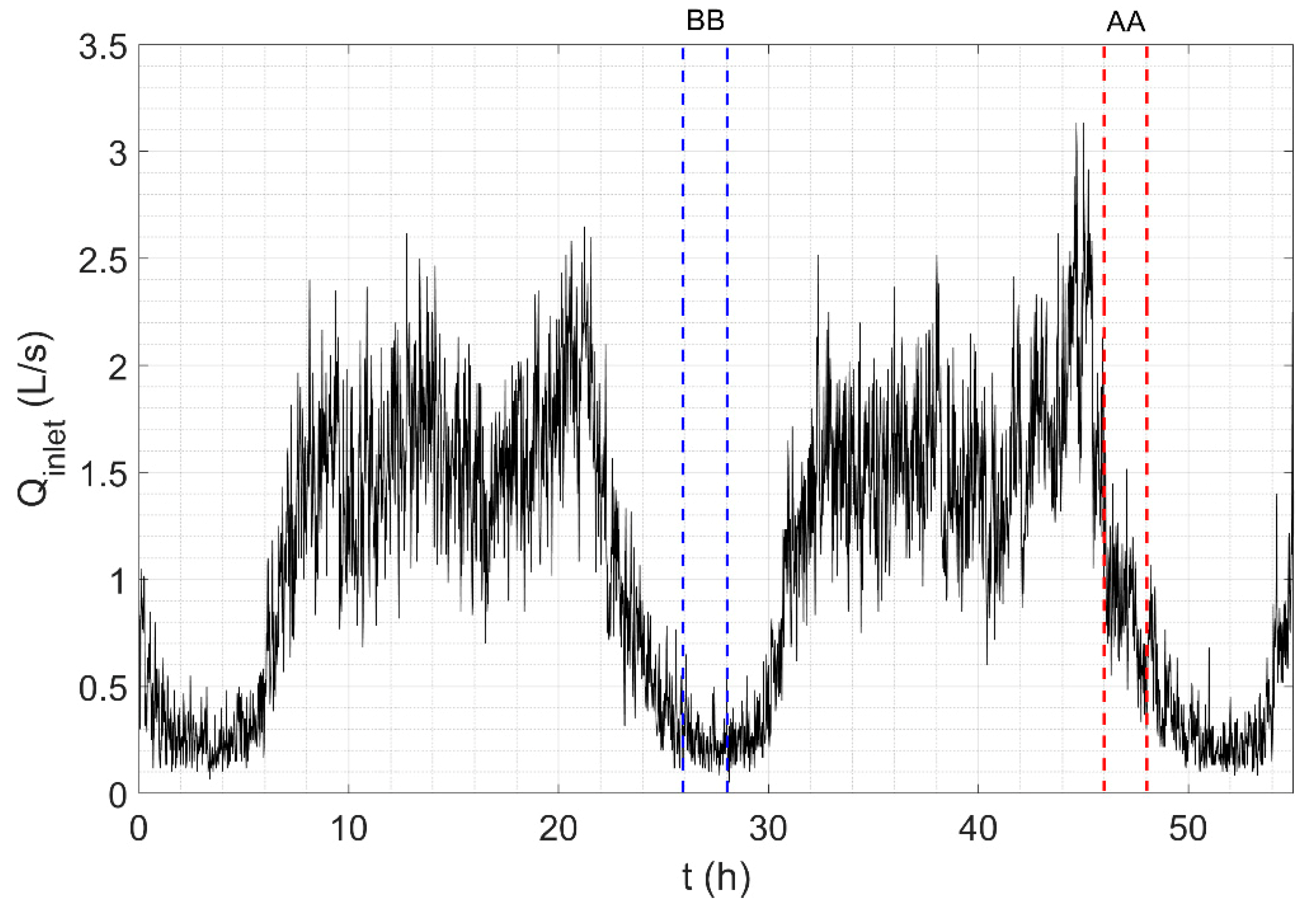
48]. The flow rates were measured at the inlet of the 160 mm diameter pipes that supply the district (where no PRV is actually installed), over a two day time window with a 1 min sampling step (from 00:00, 15/01/2018 to 07:00, 17/01/2018). Flow rates observed at the inlet section of the district metered area are in general very low, varying between 3.1 and 0.1 L/s as shown in
Figure 4.
Two distinct tests were conducted in order to characterise the behaviour of the PA-PRV with respect to different flow regimes, which were in any case in line with those of the tests in the first phase. Each test had a duration of two hours, corresponding, respectively, to the time window from 22:00 to 24:00, 16/01/2018 (period AA, see
Figure 4), and to the time window from 02:00 to 04:00, 16/01/2018 (period BB, see
Figure 4).
From an operational standpoint, the imposition of observed flow rates within the system was achieved for both test periods through the automation of the solenoid valve installed at section A, while the ball valves at B and C were kept fixed. In particular, a degree of opening of 25% was imposed for the ball valve at B while the ball valve at C was completely closed.
3. Results and Discussion
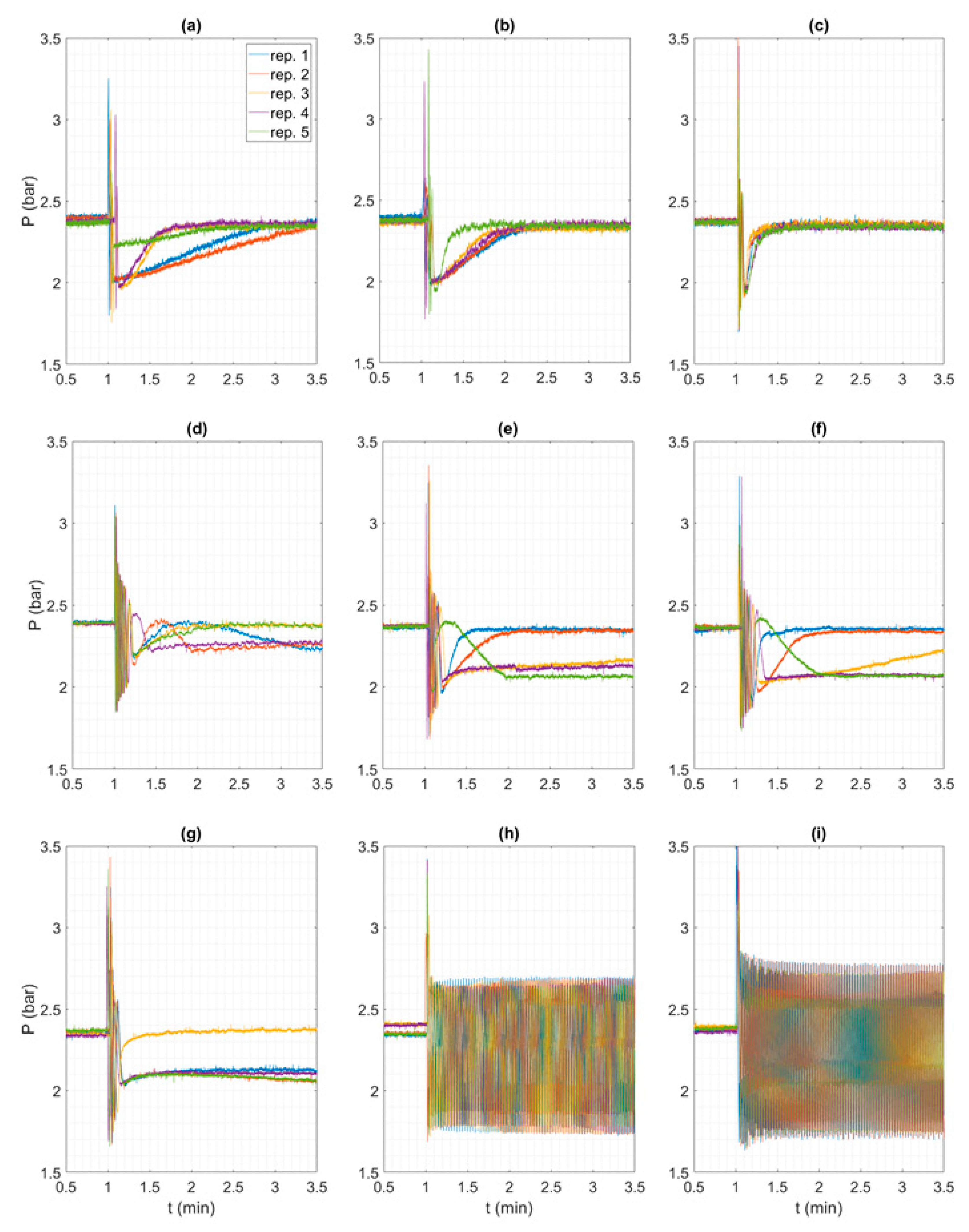
Pressure signals observed downstream of the PA-PRV (section G) are shown in
Figure 5 for the nine test configurations, each test being repeated five times. Based on the pressure signals obtained, it can be observed that the PA-PRV exhibits a correct behaviour for final flow rates Q
fin higher than or equal to 0.7 L/s (tests (a), (b) and (c) in
Table 1). Indeed, with reference to
Figure 5a–c, the pressure signal observed downstream of the PA-PRV shows some marked oscillations due to the flow rate reduction manoeuvre, but afterwards the pressure tends to stabilise around the imposed set-point.
The time it takes for the downstream pressure to become stabilised, that is, the stabilisation time intervals (hereafter labelled as STs), varies with an apparently decreasing trend as the final flow rate Q
fin decreases, as summarised in
Table 2.
In fact, although the rapid closing of the valve at section B is carried out manually and this may lead to slight differences in the manoeuvre times and, therefore, in the response of the system itself from one repetition to another also given the same test configuration (or Q
fin), in general it is worth noting that, with reference to test (a) (see
Figure 5a), the STs are around two minutes for repetitions 1, 2 and 5, and around 60 s for repetitions 3 and 4. For test (b) (see
Figure 5b), the STs generally take on lower values than in test (a): in repetition 5, ST is equal to 40 s and in repetitions 1, 2, 3 and 4 the STs are about 80 s. Finally, ST continues to decrease, with values between 38 and 46 s for test (c) (see
Figure 5c).
A further reduction of the initial flow rate within the system (tests (d), (e), (f) and (g) in
Figure 5) leads to an anomalous behaviour of the PA-PRV, which tends in some cases to quickly stabilise around the set-point (see for example repetitions 1 and 2, in blue and red, respectively, in
Figure 5f) but in others to reach the set-point in extremely prolonged times, longer than the sampling time of 6 min (see for example repetition 3, in yellow, in
Figure 5f), or to stabilise around smaller values that are approximately 0.4 bar lower than the setting value (see for example repetitions 4 and 5, in purple and green, respectively, in
Figure 5f).
Thus, it is worth noting that even though the flow rate and the pressure in the system are related and clearly depend on several factors, including the pipeline parameters and the PRV characteristics and setting, PA-PRV behaviour, in terms of imposed downstream pressure, is correct and univocal for all the repetitions of the three test configurations characterized by a final flow rate higher than or equal to 0.7 L/s, whereas looking at the repetitions of each of the six test configurations characterized by a final flow rate between 0.7 and 0.2 L/s, it is evident that the downstream pressure is not uniquely defined in the face of the same flow rate.
This abnormal behaviour was also pointed out by Changklom and Stoianov [
46], but for a diaphragm PRV, and it is defined as a deviation from the set-point or profile. The authors suggest as possible causes the blocking of control systems, the malfunction or failure of a physical component of the valve, insufficient inlet pressure, incorrect setting of the piston speed adjustment or the presence of trapped air in the control chamber. In the present case, however, the aforementioned causes should be ruled out. Indeed, the PA-PRV analysed in this study does not have an adjustment speed control system, as the operation of the device is based on the “Linear Flow Linear Control (LFLC)” technology, as described above, while any air trapped in the control chamber is eliminated by means of the air-relief valve placed on the valve body.
On the other hand, the tendency to stabilise around two set-points can be interpreted in light of a study presented by Dempster and Alshaikh [
49]. In fact, after studying the behaviour of safety valves in an industrial environment subjected to determined flow conditions, the authors show that the behaviour of these devices could be influenced by the interaction between the force acting on the disc and the spring force, for which two different conditions of equilibrium are identified.
Based on this analysis, at flow rates lower than 0.7 L/s the behaviour of the PA-PRV could be influenced by the operation of the pilot valve which, like the safety valve analysed in the study by Dempster and Alshaikh [
49], seems to have two distinct points of equilibrium that lead the PA-PRV to stabilise at different values of pressure (see
Figure 5d–g).
The difficulty of the PA-PRV in guaranteeing the set-point downstream of the valve is accentuated in tests (h) and (i): major instability occurs when the final flow rate Q
fin is lower than or equal to 0.2 L/s. Indeed, the pressure signal observed downstream of the PA-PRV starts to oscillate around an average value (lower than the set-point) with an amplitude of 0.5 bar and a frequency of about 0.5 Hz in response to the variation of the flow rate ∆Q. These oscillations are characterised by a persistent trend without damping and are comparable to harmonic motion (
Figure 5h,i). In this case, an estimation of ST is not possible. A similar result was found in the study by Ulanicki and Skworcow [
45], who showed an oscillatory behaviour under low-flow regimes due, however, to problems of stability of the electronic control system of the PRV and, in particular, to the fact that the dynamic gain, defined as the ratio between the variation of the pressure downstream of the PRV and the variation of the valve opening, does not decrease linearly with the opening. In this case, the device was controlled by a mechanical pilot, so the instability that emerged was probably an intrinsic characteristic of the device. Changklom and Stoianov [
46] have confirmed the possibility of hydraulic instability in the device in the form of pressure oscillations. In particular, the authors differentiate between high- and low-frequency instabilities due, respectively, to incorrect sizing of the PRV and the interaction between the PRV and other devices.
In the present case, pressure data sampled upstream of the PA-PRV during the tests (h) and (i) did not show significant amplitude oscillations. Thus, the PA-PRV tends to split the hydraulic system into two parts, respectively, upstream and downstream of the PRV itself, a result similar to the one presented by Meniconi et al. [
41]. Moreover, the presence of an expansion vessel between the centrifugal pump and the supply pipe rule out that this behaviour may be caused by an interaction between the pumping system and the PA-PRV.
Summing up, the first phase of tests highlights that the behaviour of the PA-PRV differs as the flow rate characterising the specific test decreases. In particular, the following characteristic types of behaviour can be observed:
B1: for Qfin ≥ 0.7 L/s, the PA-PRV functions correctly, maintaining the downstream pressure around the setting value and showing variable time intervals of stabilisation of the piston, or STs;
B2: for 0.7 < Qfin < 0.2 L/s, the PA-PRV tends to fail to maintain the imposed set-point, setting the downstream pressure around values lower than the set-point or showing extremely long stabilisation time intervals in order to reach the setting value. This behaviour can be related to an intrinsic difficulty of the pilot valve in reaching a single equilibrium configuration; and
B3: for Qfin ≤ 0.2 L/s, a condition of persistent instability is observed.
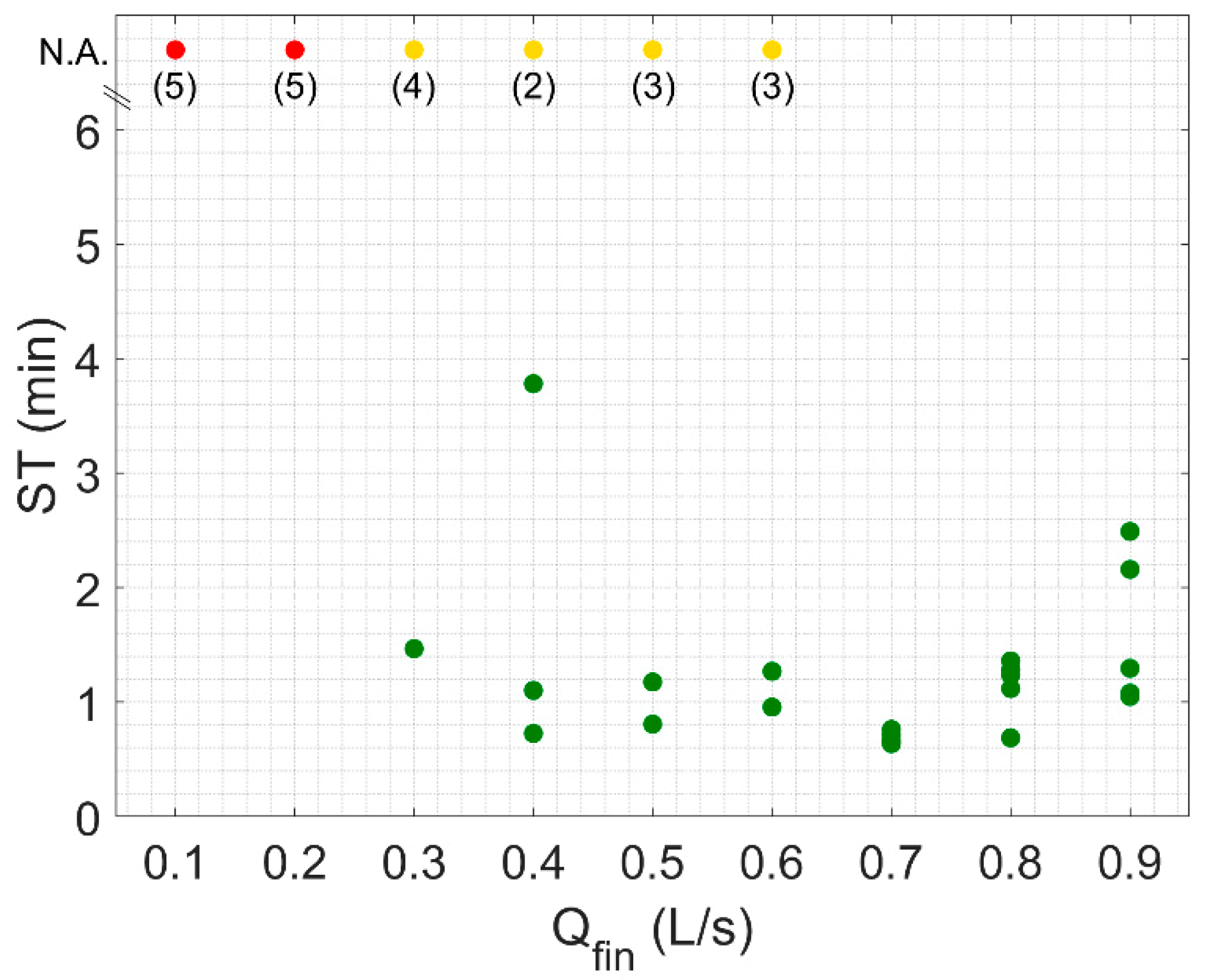
These three distinct behaviours that characterise the analysed piston valve can be distinguished with reference to the STs of the PA-PRV as a function of the final flow rate Q
fin (
Figure 6).
The green dots indicate the test repetitions during which the PA-PRV reached the set-point. In particular, with reference to Qfin ≥ 0.7 L/s (tests (a), (b) and (c)), the STs and their scattering tend to decrease as the value of the test end flow rate Qfin decreases.
Yellow dots (
Figure 6) identify the repetitions of tests (d), (e), (f) and (g) which showed a stabilisation of the PA-PRV around a lower value than the set-point or STs greater than the duration of the test (6 min). The red dots indicate the occurrence of unstable behaviour (B3).
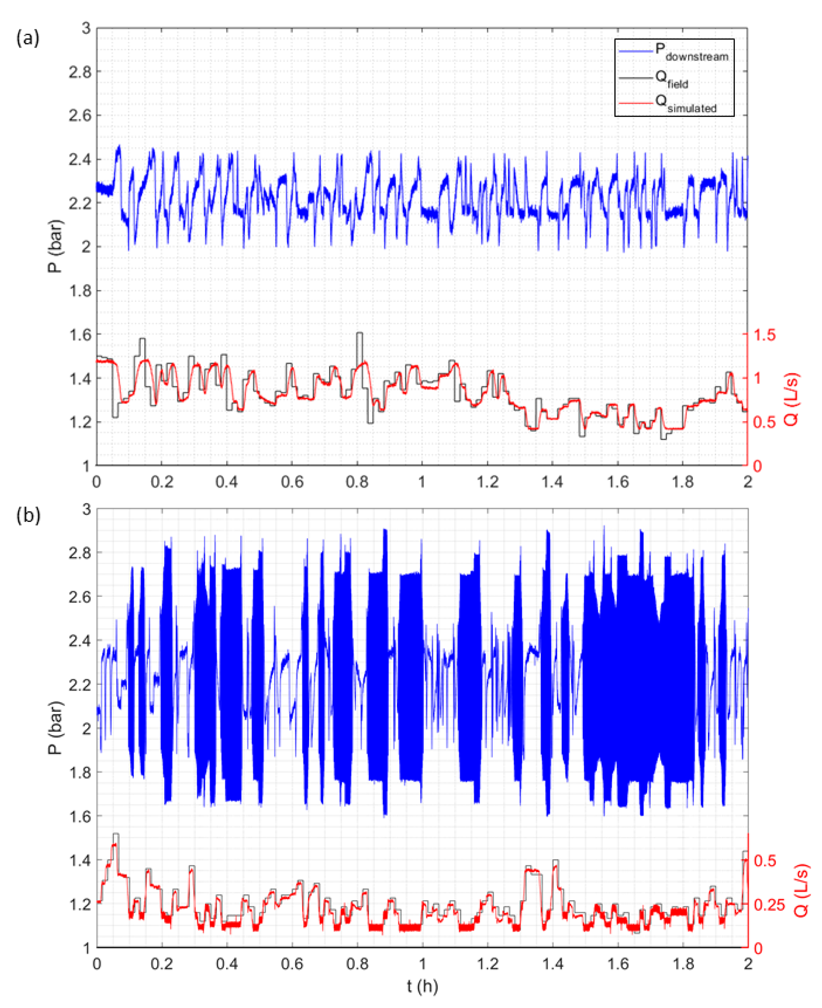
With reference to the second phase of tests,
Figure 7a,b shows the flow rate signals observed at the inlet section of the real district and imposed on the laboratory hydraulic system and the corresponding pressures sampled downstream of the PA-PRV (section G, set-point 2.4 bar) for periods AA and BB, respectively.
Firstly, it is worth noting that the imposition on the system of flow rates observed during period AA produces a simulated flow rate which tends, in general, to trace the observed one correctly. Some discrepancies are related to the manoeuvring speed and the adaptation time of the solenoid valve with remotely controlled modular opening at manoeuvring section A, which tends to reproduce smaller, more gradual variations rather than large, sudden changes in discharge. With reference to the pressure signals, the set-point is not properly maintained with the imposition of the series of observed flow rates in period AA (see
Figure 7a).
Pressure fluctuations between 2 and 2.5 bar due to the rapid variability of the flow rate regime are evident. From an operational standpoint, given the stabilisation times of the PA-PRV, which are in the order of one or more minutes, the rapid variability of the flow rate regime (1 min step) means that the PRV is unable to reach the set-point before the flow rate in the system varies again.
Moreover, when the flow rate in the system decreases below 0.7 L/s, the PA-PRV exhibits behaviours that can be traced back to B2 as characterised in the first phase of the tests.
For example, with reference to the time interval preceding the instant t = 1.8 h in
Figure 7a, the PA-PRV stabilises the downstream pressure around a value equal to 2.2 bar, lower than the set-point imposed despite the fact that the flow rate remains the same for approximately three minutes of simulation.
With the imposition of the series of flow rates observed in period BB (see
Figure 7b), the pressure signals show that the set-point is not maintained and an instability occurs whenever the flow rate becomes smaller than or equal to 0.2 L/s. This behaviour can be related to the flow rate regime characterising the system, which oscillates between a maximum value of 0.7 L/s and a minimum value of 0.1 L/s. This flow range causes the PRV to work between behaviours B2 and B3 previously defined: the instability of the PA-PRV at such low flow rates determines a pressure oscillation downstream of the device itself, which in this case is between 1.7 and 2.9 bar.
This second simulation is useful for highlighting how the occurrence of instability can occur under the ordinary operational conditions in a DMA and consequently subject a real system to stresses that are potentially harmful to pipes and hydraulic devices.
