1. Introduction
The history of using the energy of water is comparable with the history of human civilization. In recent decades, the generated power from water (hydropower) has been increased considerably as a significant source of renewable energy. Worldwide generation from hydropower, which varies each year with shifts in weather patterns and other local conditions, was an estimated 1292 GW (4200 TWh) in 2018, which is about 25.6% of the global electricity generation and 15.9% of renewable electricity (
Figure 1) [
1]. Pumped-storage hydropower (PSH) systems have played an essential role in the flexibility of renewable energy sources such as the integration of wind and solar energies. The global PSH installed capacity in 2018 was 160.3 GW, which increased by about 1% during the year [
2]. The hydropower capacity has been growing quite rapidly during the last few decades and the forecasts show that it will remain the world’s primary source of renewable power in 2024. Hydropower will account for 10% of the total increase in renewable capacity based on a forecast for the period of 2019 to 2024 by the International Energy Agency (IEA) [
3]. The main source of renewable electricity in Europe is provided by hydropower, with an estimated electricity generation of 643 TWh (pump-storage not included), which accounts for 17% of the total generation [
1]. Despite the fact that most of the European countries do not provide good potential in the hydropower generation field due to their flat landscape, some countries, like Norway, Russia and Portugal, can provide a good contribution in hydropower energy generation [
4].
Traditionally, hydropower facilities can appear in different types, namely impoundment (storage), pumped-storage, run-of-river, offshore hydropower plants and inline solutions in the water sector. Hydropower potential can be categorized in terms of the installed capacity as large (>10 MW), small (<10 MW), mini (<1 MW), micro (<0.1 MW) and pico (<0.005 MW) [
4]. Indeed, many of the potential hydropower spots cannot be exploited as a result of technical and economic reasons, but this estimation proves the huge potential behind the hydropower energy generation [
4]. Traditional and large hydropower plants are mostly of the impoundment type, which calls for large financial investment. In addition, the development of large hydropower plants can trigger big environmental impacts and requires specific topographical conditions. For this reason, this study mostly focuses on less expensive technologies.
Apart from the traditional hydropower types, which are mostly of large potential types, some new lower potential types have been introduced and examined recently. Among them, PSH has been very promising. This system takes advantage of off-peak electricity to transfer water to the upper reservoir using a pump and then produces electricity from the potential energy of water during peak hours [
5,
6,
7]. PSH is currently the most common form of on-grid electricity storage, with an operating condition which is very well fitted to reversible turbomachines, namely Francis or pumps as turbines (PATs) [
8]. The recent increasing influence of variable renewable energy sources forces innovations in energy storage technologies [
9]. This has been the main motivation behind other PSH types, such as underwater PSH (UPSH), which some studies have shown can be competitive with conventional PSH and compressed air energy storage (CAES) systems. In UPSH, seawater acts as an upper reservoir and an underwater tank has the role of a lower reservoir working with the same concept of a conventional PSH [
9].
Accordingly, the novel renewable energies should be designed on the basis of new technologies and small decentralized hydropower plants to decrease the investment costs and increase the reliability and flexibility of the renewable source by making it less dependent on climate factors [
10,
11,
12]. There is a huge untouched potential in the micro-hydropower category with low and medium heads available in different water conveyance systems [
13]. In that sense, energy recovery in potable water networks (urban, rural), irrigation water networks and wastewater and process industry systems received a lot of attention. For this purpose, the pump as turbine (PAT) systems have been recently under consideration and increasing studies have come out addressing different aspects of that [
14,
15]. PATs are hydraulic pumps that operate in reverse mode for energy production purposes by means of a connected induction motor working as a generator [
9]. The operational cost of a PAT is five to 10 times lower than that of a conventional turbine [
16]. However, the contribution to renewable energy sources is very slight, which may come from the lack of knowledge, some institutional barrier for implementation and interest. But lately, several studies have been published, mostly examining the PAT application in the water sector through the REDAWN project. In a study [
17], a hybrid solution of leakage reduction and energy recovery using PATs was analysed in rural water distribution networks in Ireland, showing the significant contribution of generated power in local energy demand. Another study [
18] focused on the off-grid PAT combined with a self-excited induction generator, which led to a boost in system efficiency of 20%.
Besides rural and urban water networks, irrigation water networks also have provided great potential in energy recovery, where a substantial amount of energy used for water distribution can be recovered [
19]. The energy harvesting in irrigation water networks is relatively a new area, with very challenging concerns because of the flow variation. Still, studies show that high potential exists in this area [
20,
21,
22]. Although studies have shown that conventional turbines (Francis, Pelton, Kaplan, Turgo, and crossflow) can still compete with new emerging technologies, the new technologies might provide more economic solutions due to a modular design [
23]. However, new unconventional hydropower solutions are putting a new spin on hydropower generation for future energy generation [
24].
Recently, the CAES systems were considered as a proper solution for geographical conditions in which PSH and PATs cannot be implemented. The first test of a CAES system was in 1949 by Stal Laval, when he registered the first patent of CAES to store energy in the form of compressed air in underground caverns. The basic concept of a CAES is based on stored compressed air which is released to generate energy when needed [
25]. Currently, two large capacity plants exist in Germany and the USA, but a lot of studies are appearing in the literature focusing on different solutions, such as the thermodynamic behaviour and hybrid solutions, along with some novel conceptual ideas. A lot of studies have focused on the thermodynamic inspection of CAES systems which have led to the development of different types of CAES system, such as advanced adiabatic CAES (AA-CAES), isothermal CAES (I-CAES), adiabatic CAES (A-CAES) or others [
26,
27].
In two recent studies, a hybrid solution was proposed to assess the combination of PSH and CAES (pumped hydro CAES or PH-CAES). These studies [
28,
29] presented an experimental investigation of a PH-CAES system operating using a Pelton turbine. The reported efficiency for the PH-CAES system was 45% and the authors claimed that, unlike conventional CAES systems, this system works with constant power [
28,
29]. In another study, a new concept for the CAES system was a geographically independent system which was proposed and tested in the laboratory. The feasibility of the concept was proved while reporting the experimental electrical roundtrip efficiency and hydraulic (thermodynamic) efficiency of 24% and 97%, respectively. The authors mentioned the energy loss in the machinery as the main reason for a low electrical roundtrip efficiency [
30]. Also, some new concepts for using compressed air have been tackled by some researchers, either in underground caverns or underwater inflatable balloons [
31]. Also, another study was published to evaluate the dynamic behaviour of air-water for pressure storage and recovery [
32].
Correspondingly, this study aims to present a new conceptual idea of energy storage/recovery using Transient Flow-Induced Compressed Air Energy Storage (TI-CAES). The transient flow is induced in the system by creating a waterhammer event, which has been widely studied and addressed in the literature from different aspects [
33,
34], giving enough knowledge to employ it for this purpose. For that, experimental data were collected in a system composed of a water pipeline, a compressed air vessel (CAV) and some valves. The results of experimental investigations are used to assess two ideas: (a) generating energy by means of a water turbine; (b) pumping water using the stored pressure inside the entrapped air.
2. System Description
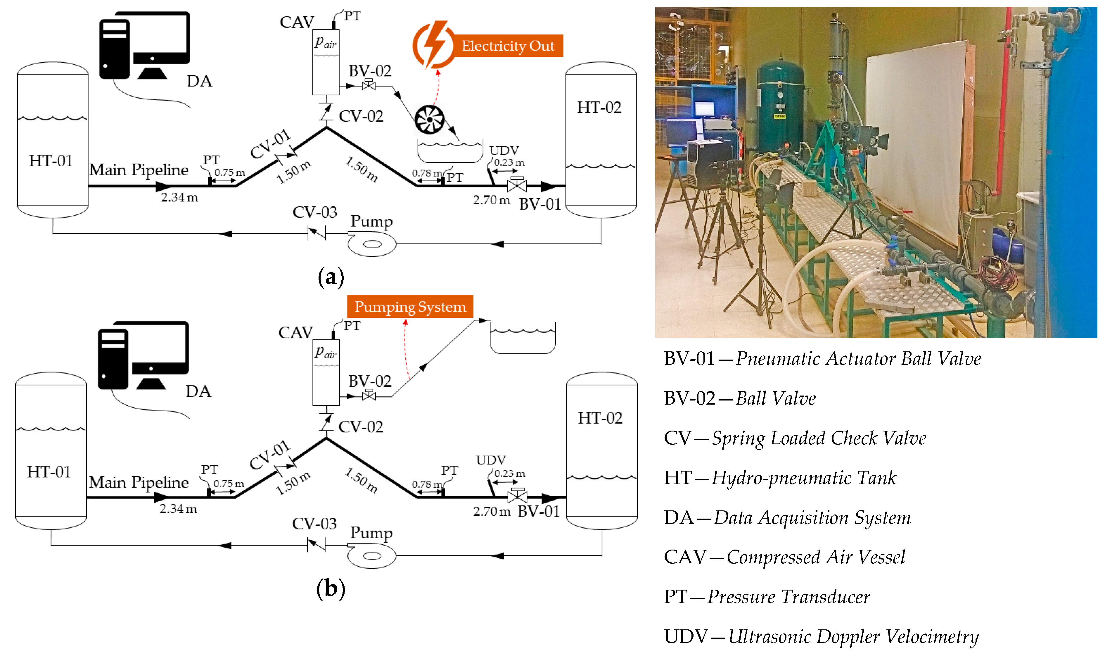
A schematic drawing of the experimental system is presented in
Figure 2, showing the auxiliary components for the purpose of this study. The system is composed of PVC pipes with a nominal diameter of 63 mm and the nominal pressure of 16 bar connecting two hydro-pneumatic tanks. By means of recirculating the flow, a steady-state flow condition is established. The data acquisition system records the pressure values and also the velocity profiles. The pressure sampling is done using S-10 WIKA pressure transducers, with the maximum sampling error of ±0.5% as reported by the manufacturer [
35]. The velocity profiles are measured by an ultrasonic doppler velocimetry (UDV) system from MET-FLOW offering an accuracy of ±1 ms [
36]. The sampling rates for pressure and velocity measurements were 910 and 10 Hz, respectively. Three pressure transducers were installed in the system, as shown in
Figure 2. In the measurements, the charging/discharging flow rate and pressure were recorded for different steady-state velocities in the main pipeline (represented by Reynolds (Re) number in the current paper) and the volumes of air inside the CAV. A volume fraction ratio (VFR) has been defined as the volume of air over the volume of CAV in percentage to express the volume of air inside the CAV. The CAV can operate through two different approaches, i.e., the electricity dispatch system by means of a hydro-turbine (
Figure 2a) and the pumping system (
Figure 2b). The transient flow is induced into the system by the action of BV-01, a ball valve manoeuvred by an electro-pneumatic actuator from +GF+ company [
37].
The system can be used to generate energy using a hydro turbine, when the CAV works in two stages, i.e., water charge and discharge (
Figure 2a). In the water charge stage, the BV-01 is actuated in a closed/open action to induce a waterhammer into the system. A pressure surge will be propagated in the system by the upsurge occurrence travelling in the upstream direction. As a result of the pressure surge and the special arrangement of CV-01 and CV-02 in the system, the backflow will be directed towards the CAV. The pressure of air in the CAV (
), which initially was equal to the atmospheric pressure, will increase due to the compression of the air. In the water discharge stage, since the BV-02 is in open position, the compressed air starts to expand and consequently expels water through BV-02. The charge and discharge stages can be performed frequently. In this study, 9 charge/discharge stages were examined, meaning 9 waterhammer event occurrences.
On the other hand, the system might work for pumping (
Figure 2b). For that, the CAV operates as well in the charge and discharge stages. In the charge stage, the BV-01 closes and opens to create upsurges. The pressure surge will be stored in the CAV (because the BV-02 is closed). The waterhammer action is repeated until the desired or maximum pressure is reached inside the CAV. Then, the BV-02 will be opened, allowing compressed air to expand and drive water out of the CAV. Depending on the pressure of the air, it can elevate water to a significant differential level or compensate head losses in a pumping system.
The current study focuses on the energy generation idea (
Figure 2a), in which the transient effect includes 9 consecutive waterhammer events taking a total time of 18 s. This effect is created by the closing/opening action of BV-01, taking 0.4 s (0.2 s for each opening or closing action). The major measuring parameters in this system are the main pipeline pressure, the air pressure, the air volume (displayed by VFR), the flow velocity and the CAV outlet flow rate. The measured range for major parameters of TI-CAES system in the current experimental tests is presented in
Table 1. The initial pressure of the whole system has been set to the atmospheric pressure. The pressure in the main pipeline starts fluctuating upon starting the transient event. When the transient event finishes, the pressure in the main pipeline returns to the initial condition. The flow condition before and after the transient event should be the same.
3. Parametric Analysis
The pressure variation in the entrapped air within the CAV is recorded, and demonstrates the charge and discharge stages through pressure spikes (
Figure 3). The pressure spikes caused by the compression of the air under the waterhammer action shows different values and a fluctuation behaviour based on the air size (represented by VFR) and Re of the pipeline flow. Two pressure variation results are presented in
Figure 3 for a constant Re = 155,000, showing quite different fluctuation and minimum pressure values when compared to the initial pressure (
).
It was analysed how the mentioned different pressure consequences can affect the functionality of the TI-CAES system. For that, a thermodynamic approach was used to analyse the pressure data. Thermodynamic behaviour in closed air vessels is traditionally modelled using the polytropic equation:
where
and
represent the air-phase pressure and volume, respectively [
38].
n is a real number known as the polytropic exponent which includes the heat transfer and depends on the type of thermodynamic process (usually for isothermal process
n = 1 and for adiabatic process
n = 1.4) [
39]. In order to define the
n value, one should first determine the type of the thermodynamic process. Previous studies proved that, for rapid transitions, the process is close to adiabatic with zero heat transfer [
39,
40,
41,
42,
43,
44,
45,
46]. However, in this kind of transient, an average value of
n = 1.2 is suggested [
35,
43], because of the different behaviour of the transient phenomenon from the beginning of the process to the end. In the study [
39], it was demonstrated that, for medium and big air volumes, the polytropic exponent
n = 1.2 gives very good agreement with the measured pressures. According to this, the new volume of air, changing due to transient (
) and corresponding to the new pressure surge (
), is calculated using Equation (2).
where
and
stand for the initial pressure and volume, respectively. Hence,
corresponds to a new volume due to changing the pressure from
to
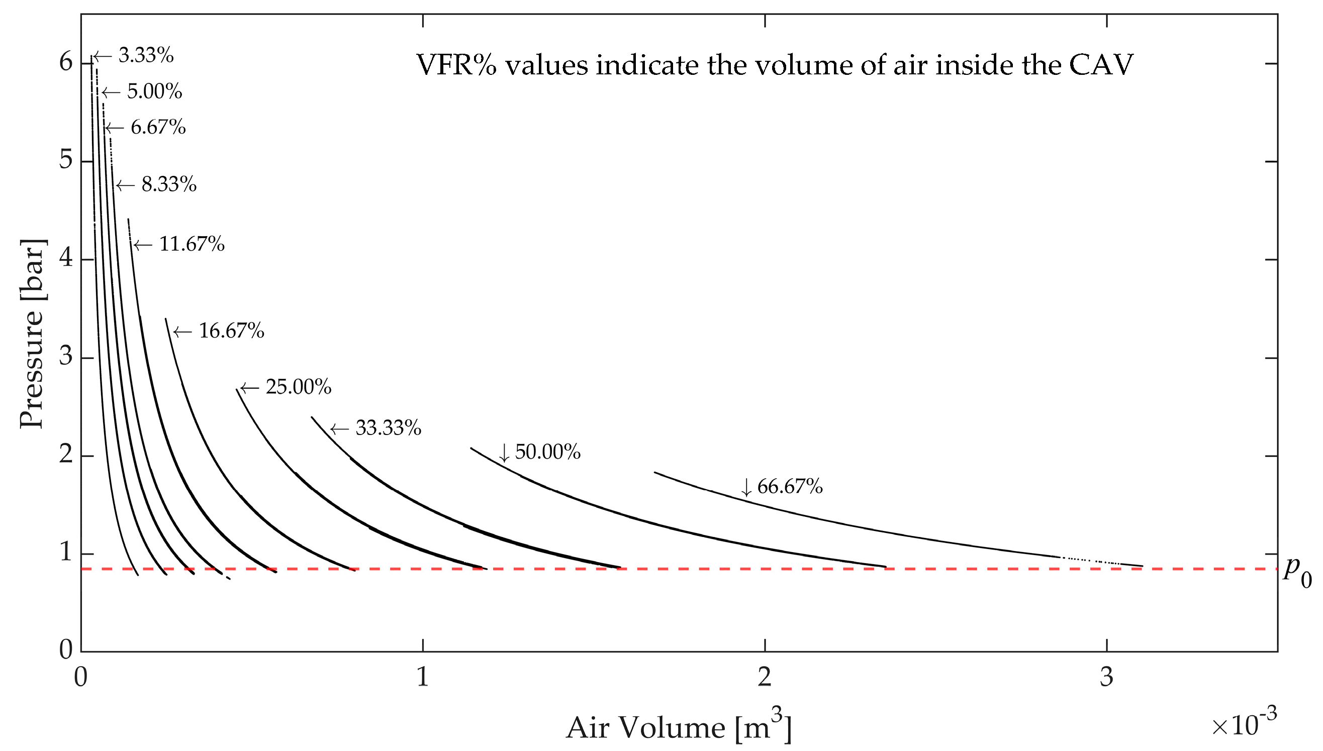
. Based on that, the pressure–volume diagram for different volumes of air inside the CAV is plotted in
Figure 4. It demonstrates that bigger changes in the air volume correspond to higher VFRs.
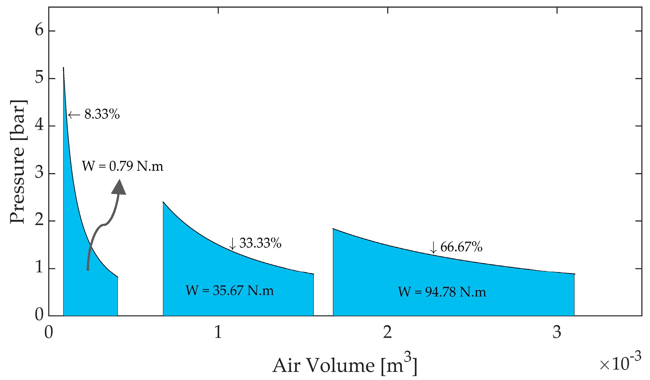
The area below each pressure–volume curve shows the work done by the expansion of air for a specific VFR. In
Figure 5, the works done for bigger VFRs are greater than those with smaller VFRs, promising a higher hydraulic power generation.
The hydraulic power can be determined by integrating the work over the charge and discharge time. It can be calculated using Equation (3).
where
is the work and
is the flow rate. Two approaches can be tackled in the calculation of
since it is fluctuating during the time as shown in
Figure 3. Either
can be considered as the integration of the pressure variation graph over time or a function of time. For the first approach, the integral of
along the time was calculated for different tests using Equation (4), in which
stands for integrated pressure values.
The resulting integrated pressure values were divided by
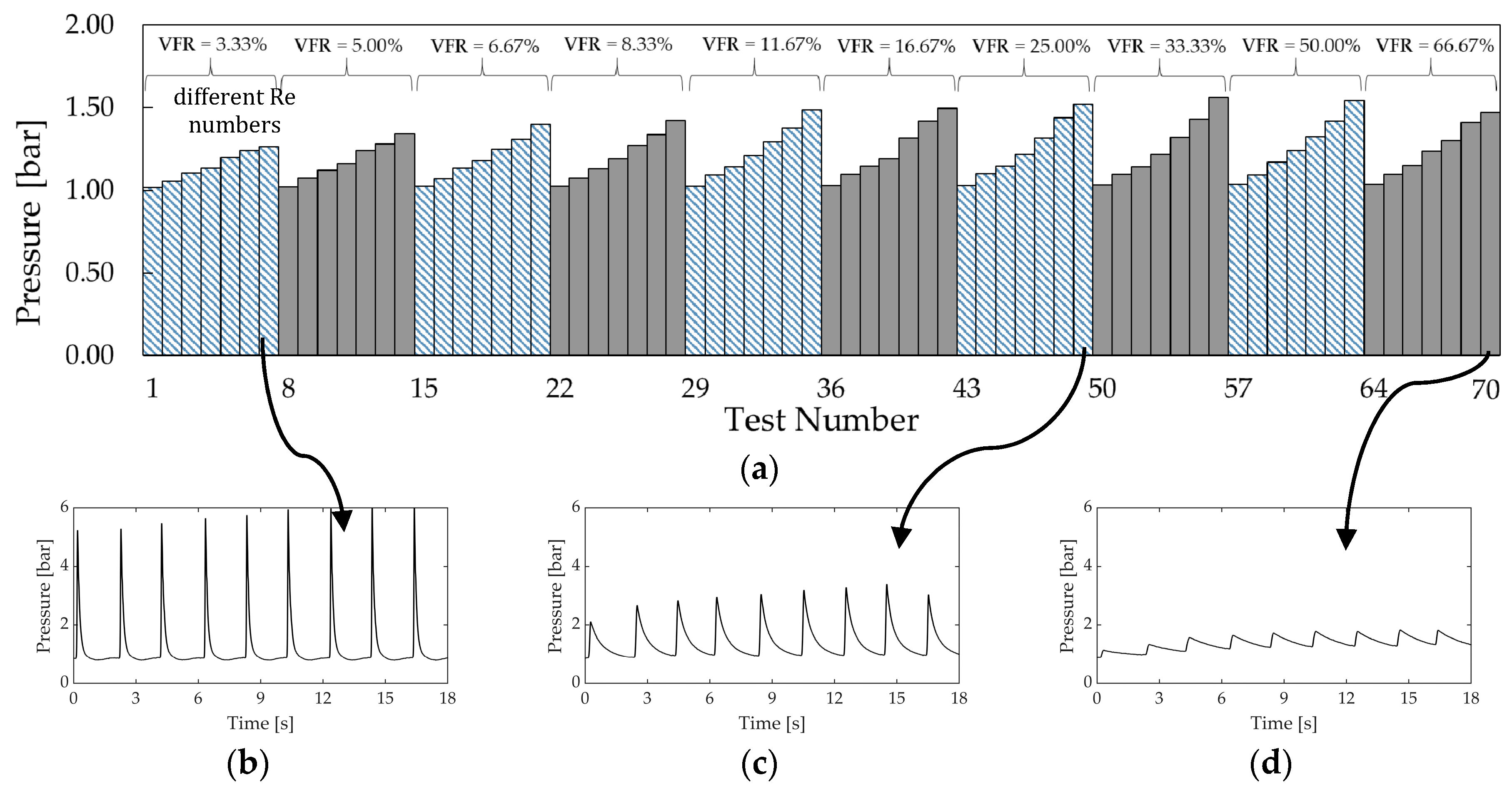
(the total transient events’ duration) to achieve an average pressure. The attained average pressures are presented in
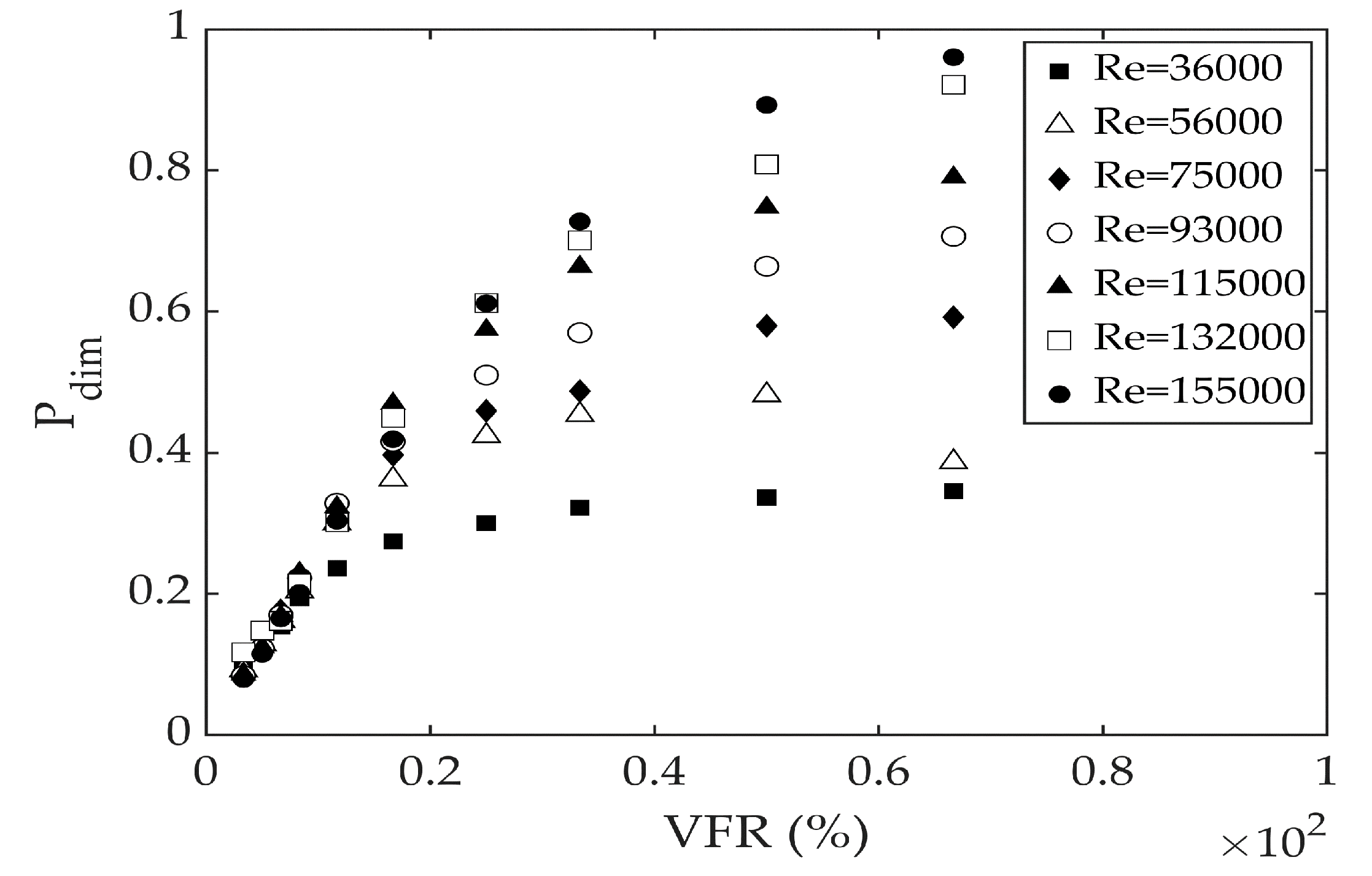
Figure 6a for different VFRs and Re numbers. Despite very high peaks for smaller VFRs, as shown in
Figure 6b, the average pressure is lower, and the highest average pressure belongs to 10% < VFR < 60%. For each VFR, pressure results of seven different Re numbers are shown in
Figure 6a, starting from low Re to high Re, including 36 × 10
3, 56 × 10
3, 75 × 10
3, 93 × 10
3, 115 × 10
3, 132 × 10
3, and 155 × 10
3.
In the second approach, the hydraulic power can be calculated using Equation (3) considering
as a function of time (
Figure 7). The resulting power will be a function of time, as presented in
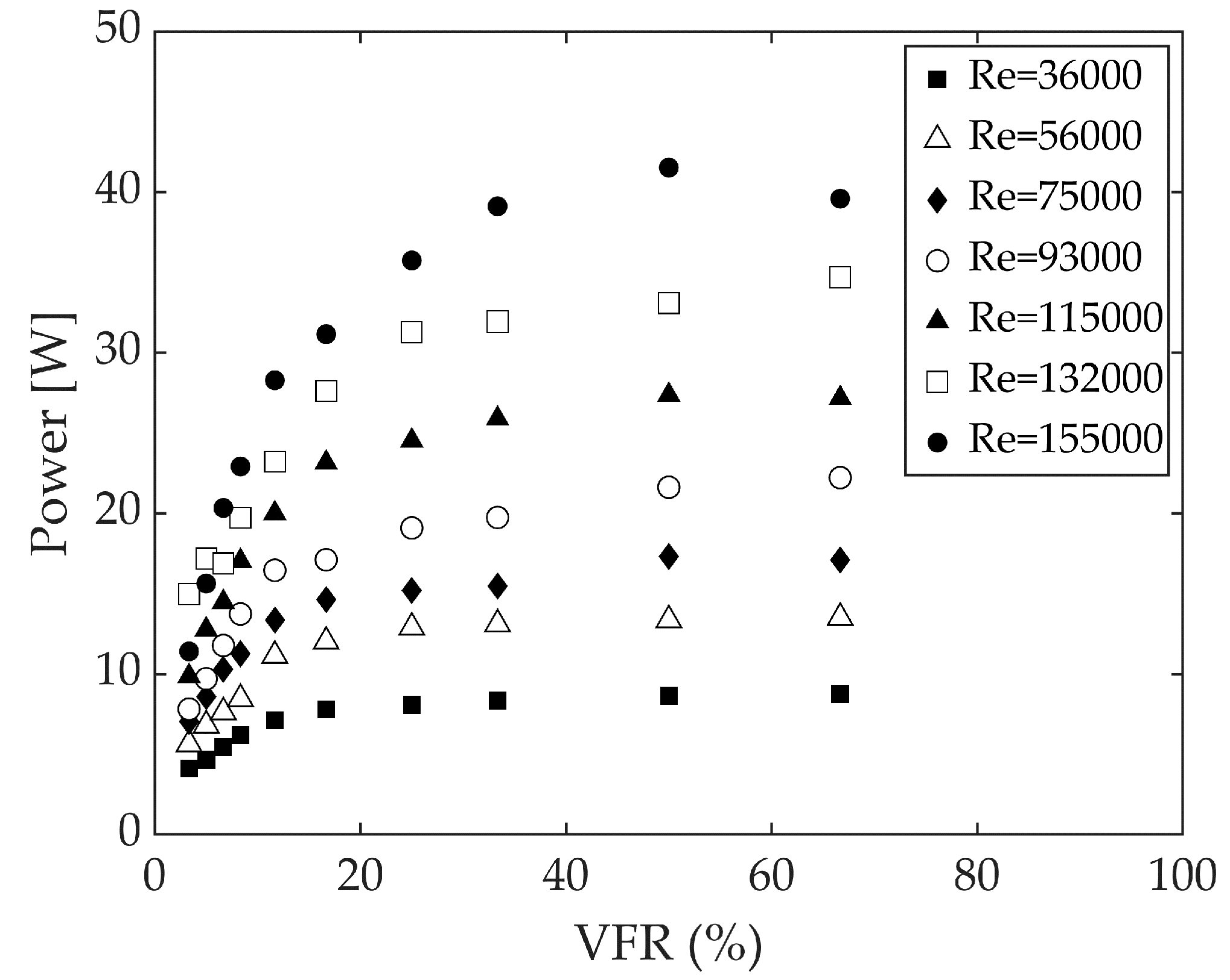
Figure 7. As is evident in this figure, by increasing the VFR (i.e., increasing the air volume) the maximum spikes of achieved power are decreased. But, on the other hand, the minimum attained power with time is higher. The maximum attained hydraulic power is 90.08 W, which is a power related to VFR = 8.33% and Re = 155,000.
The hydraulic power of CAV was estimated using Equation (3) when the
is calculated from both abovementioned approaches. Both calculation approaches were found, as expected, to give the same values of power as in
Figure 8. Considering the small volume of CAV in these experiments (4.7 L), and also the very short time associated to the transient events (only 18 s), the achieved power can be a significant and promising value for higher Re numbers.
4. Recovery Flow Behaviour
To approach the energy recovery concept in the TI-CAES system, it is important to verify the consistency of the main pipeline flow with less perturbation and possible dissipative effects when inducing waterhammer events. For this purpose, the velocity profile in the transient was recorded by means of ultrasonic doppler velocimetry (UDV) [
47] to see how the waterhammer action affects the flow characteristics. As studied by Brunone and Berni [
48], for a constant flows rate, the shape of velocity profile in a fast transient condition is very different from the steady-state one.
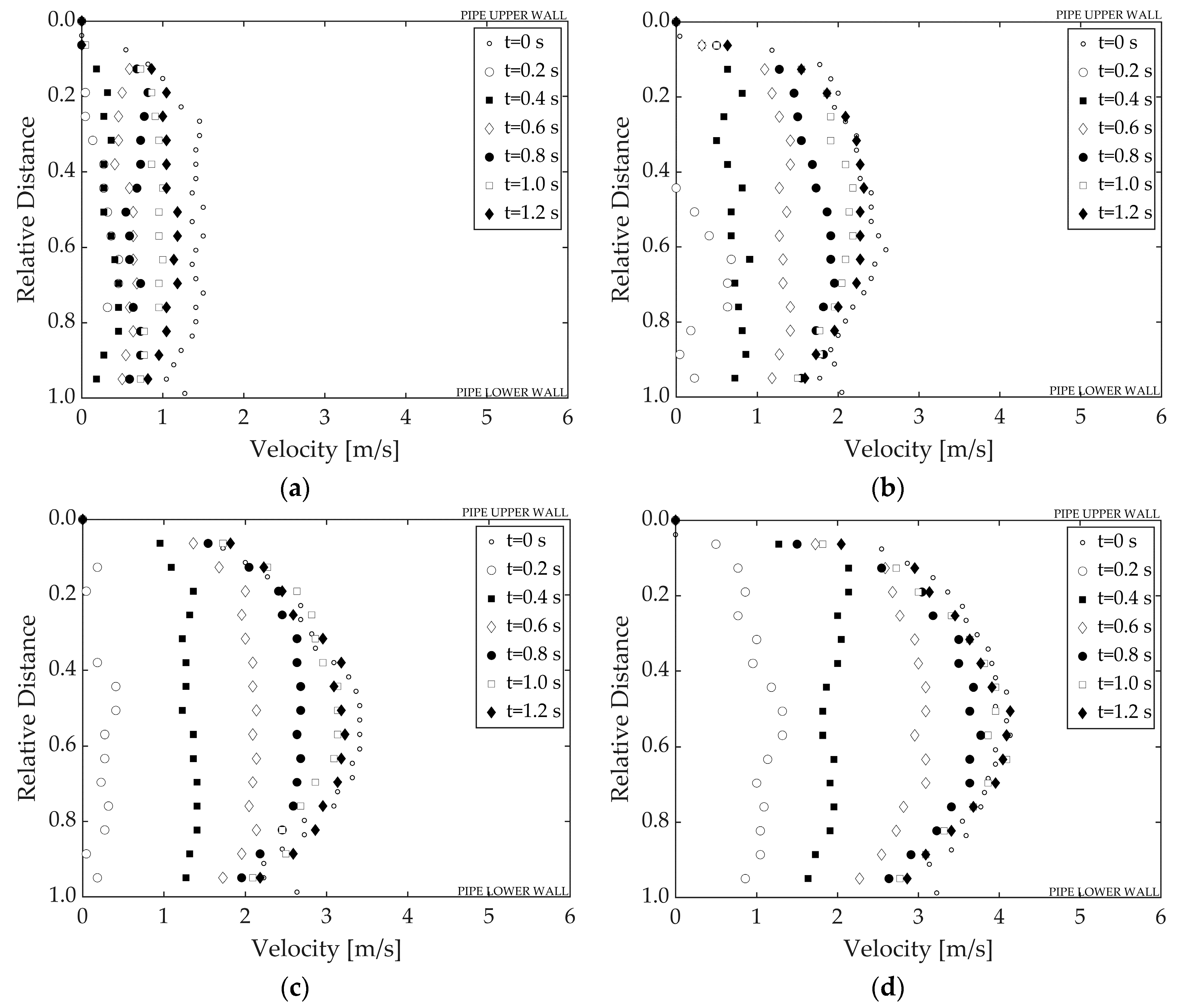
Figure 9 shows the plot of the variation of velocity profiles based on a 0.2 s interval. The time intervals that were selected were small enough to show the variations of the velocity profiles in detail during the transient. In the majority of the cases, the flow returns to the initial condition in around 1.2 s.
By calculating the velocity differences between a transient mean velocity (
) and the initial mean velocity (
) and dividing it by maximum initial velocity as
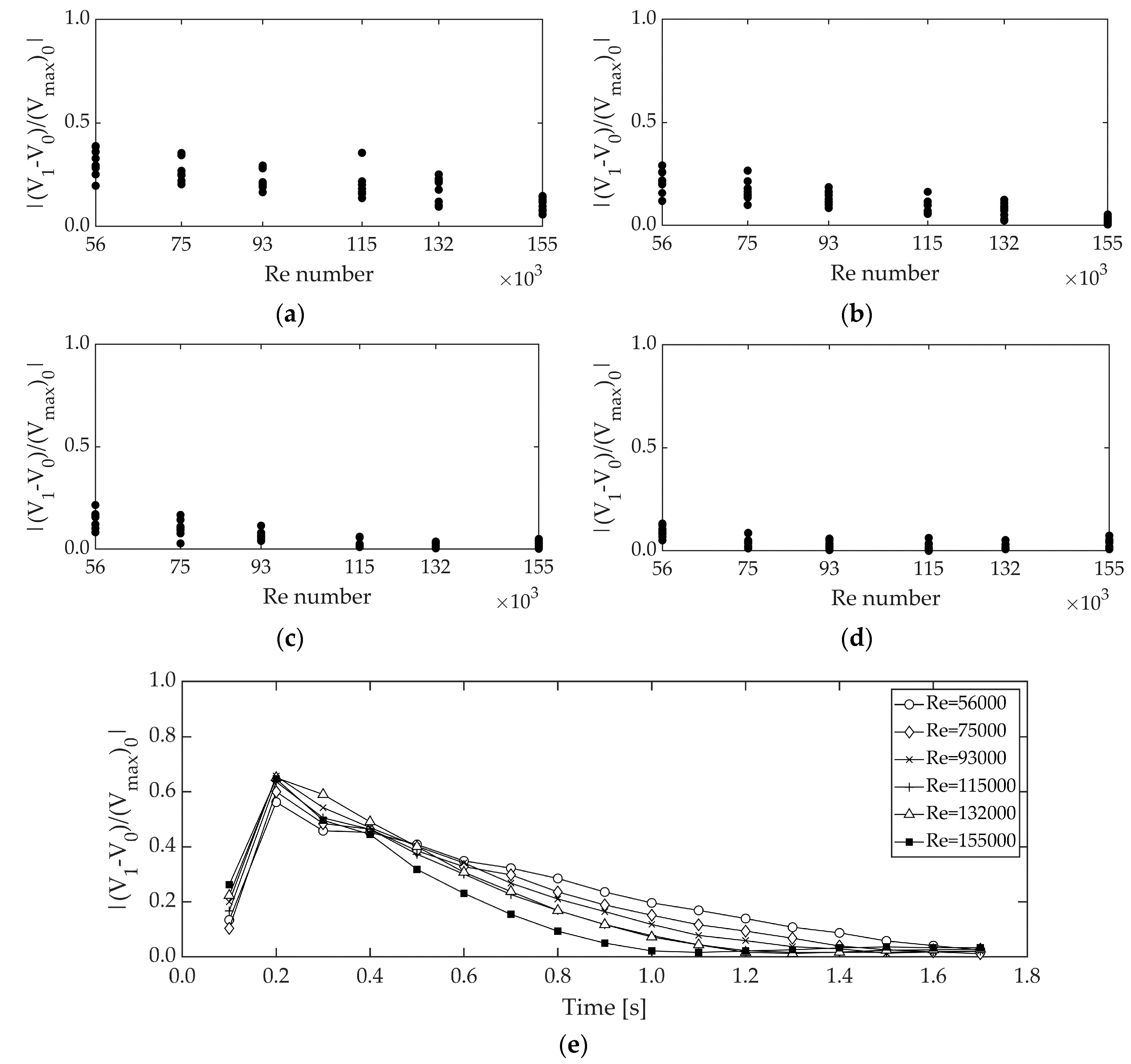
, an index for the velocity change can be achieved for further evaluation. It can help us to understand how much the velocity is going to change with time and provide information about the dissipative effects associated to flow velocity. This parameter is plotted in
Figure 10 for all the tests and time steps of 0.8, 1.0, 1.2 and 1.4 s from the beginning of the transient event. The selected time steps are the closest time steps to the initial conditions, making the comparison easier. As can be seen in
Figure 10a–d, the velocity index is very small after 1 s from the beginning of the transient event, proving the recovery of initial flow conditions. Also, it can be deducted that the initial condition recovery occurs better for higher Re numbers.
As a general conclusion, the initial flow velocity recovery with time is plotted in
Figure 10e, showing the highest difference in the time of valve closure (0.2 s) and recovering the flow very fast upon re-opening the valve. As a result, the flow change during the current transient event can be recuperated with almost neglected dissipative effects for the main flow conditions.
5. Dimensional Analysis
In this section, the Buckingham pi theorem is exploited to study the transient hydraulic behaviour caused in the CAV. The flow is based on the pressure with the same liquid (water) being adopted in the model and prototype. So, on the basis of dimensional analysis, a scale factor is defined by:
where
is defined as a scale parameter of model dimension over prototype dimension. The subscripts
and
stand for model and prototype, respectively.
The CAV (as an air vessel) can be reproduced similarly to a reservoir, where the gravity force is the main predominant force. The parameters, demonstrated in
Table 2, are important in the operation of the CAV in the TI-CAES model functionality (represented by subscript:
m):
Applying dimensional analysis is possible to forecast the characteristic parameters for different length-scales, supposing the similarity law applied only to the CAV operation, since dimensions and characteristics of the model were obtained based on the Froude and Allievi similarity, and the effect of viscosity forces on the combined friction effect of the flow inside the tank and inertia forces were neglected. Hence, from the basic equations of dimensionless variables, the compatibility between the Froude and Allievi criteria is obtained by imposing that the elastic wave velocity scale (
), and the liquid velocity scale (
); both are equal to
. This criterion corresponds to the assumption that the Mach number (V/c) is constant [
49]. Therefore, for example, with
= 1/10, it was necessary to ensure, in the experimental installation, a slower speed than the prototype. Thus, for the wave speed of 1000 m/s in a prototype, the equivalent in the experimental installation should be 316 m/s. This reduction has been achieved by selecting PVC material for the pipe. Failure to comply with Reynolds’ criterion leads to the unit pressure drop not being similar. However, given that the objective of the study is the analysis of the total integrated pressure (
) that occurs in the transient time, it is assumed that the effect of friction losses are not relevant for this type of study, as proved in former research [
49].
In this context, by putting different variable scales as a function of the size, one can get the following scales for different parameters based on Froude similarity:
| Velocity scale: | | (6) |
| Time scale: | | (7) |
| Acceleration scale: | | (8) |
| Flow rate scale: | | (9) |
| Mass scale: | | (10) |
| Force scale: | | (11) |
| Pressure scale: | | (12) |
| Energy scale: | | (13) |
| Power scale: | | (14) |
As a result, the transient or waterhammer event time, flow rate, power and energy in the prototype can be calculated using the following equations:
The measured values of pressure and flow rate related to Re = 155,000 (corresponding to highest achieved power) along with physical specifications of the experimental system were used to calculate the hydraulic power (the same data as
Figure 8) and energy of the system, as shown in
Table 3. The data for different air volumes (VFRs) are presented in
Table 3 to be comparable with later scaled-up data of prototypes.
The experimental values shown in
Table 3 are used to calculate the scaled-up values for three length-scales of 1/10, 1/20 and 1/25 presented in
Table 4,
Table 5 and
Table 6 for the same Re = 155,000, demonstrating an estimation of the installed power and available energy for the respective prototypes.
6. Discussion
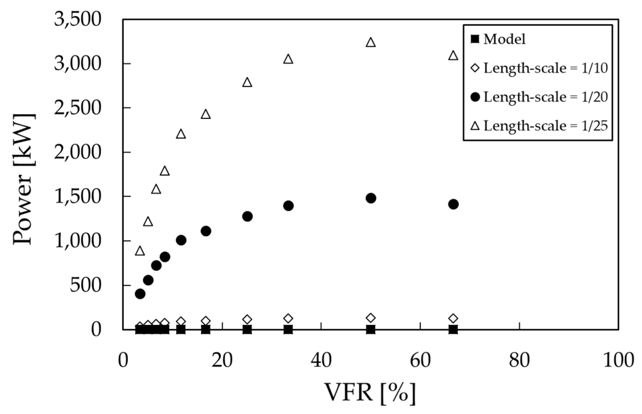
The results presented in the current study are based on measurements in an experimental model and a set of properly developed analyses. This study inspected the TI-CAES idea from different aspects and reported different achievements, most importantly the amount of attainable hydraulic power. The presented data for three different prototypes demonstrate encouraging values of hydraulic power having the maximum values of 131.33, 1485.79 and 3244.46 in kW for the length-scales of 1/10, 1/20 and 1/25, respectively, while the maximum power of the model was equal to 41 W. The power grew considerably by increasing the length-scale, as can be seen in the comparison of the length-scales of 1/20 and 1/25 in
Figure 11, when the maximum power growth is more than double, changing from 1485.79 to 3244.46.
Isolating the CAV from the main pipeline, to observe the behaviour of air in charge/discharge phases, it can be concluded the CAV behaviour does not depend on the Re number. This has been justified earlier in the discussions of
Section 5, since the friction factor effect in the CAV can be omitted. However, the CAV receives influence from the main pipeline in each waterhammer event. So, as presented in
Figure 8, the Re number in the main pipeline will affect the output hydraulic power. The above results showed the outcomes only for a Re = 155,000, this being the highest tested one. In order to have an idea of how the hydraulic power varies for different Re numbers (i.e., different flow velocities in the main pipeline), a dimensionless parameter is defined as Equation (20) by removing the effect of CAV volume and maximum pressure:
where
is the maximum recorded
for each individual test in the experimental system. The dimensionless graph in
Figure 12 shows that for VFRs < 20%, the power in different prototype scales does not depend on the Re numbers of the main pipeline flow. Nevertheless, bigger VFRs are more impressionable and therefore for VFRs > 20%, the power will be more dependent on the Re number of the main pipeline flow.
The results show that the CAV is working in charge/discharge cycles by the compression/expansion of the air after each waterhammer occurrence. The charge/discharge action of the CAV includes two pressure values of
(the initial pressure) and
(the transient pressure in each cycle). Small VFRs produce very high peaks, as presented in
Figure 3, creating the expectation to have higher powers for small VFRs. In fact, due to the direct relation between hydraulic power and pressure, the variation of power during the transient time will also include high power peaks for small VFRs, as presented in
Figure 7. Regardless, the total hydraulic power during the test time calculated based on an integrated pressure value (see
Figure 6) will be higher for bigger VFRs. In fact, for big VFRs, the air–water interface encounters a big displacement upon receiving the first pressure surge. Since the time interval between waterhammer repetitions is small, the available time is not enough for the air–water interface to return to the initial position and as a result, the initial pressure (
) is not recovered (see
Figure 3b). This will be repeated in the next entrance of the pressure surges into the CAV as well. So, after a while, the pressure of the whole CAV increases, leading to less displacement but a higher pressurized CAV system that generates greater outlet flow rate and consequently hydraulic power. This issue has been proved also via the expansion work analysis in
Figure 5.
In another part of the study, the consistency of the main pipeline flow was studied as another significant parameter in the feasibility of the TI-CAES, verifying a very short-lasting change in the velocity profile of the main pipeline. In addition, the maximum flow rate taken from the main pipeline was equal to 0.29 L/s (as shown in
Table 3), indicating a total volume of about 5 L for the tested transient time (i.e., 18 s). These values are less than 4% of the main pipeline flow and the corresponding volume for Re = 155,000, which confirms the flow consistency and limited perturbation again.

