Remediating Contaminated Groundwater with an Aerated, Direct-Push, Oxidant Delivery System

 ,
,
Abstract
:1. Introduction
2. Materials and Methods
2.1. Treatability Studies, Oxidant Manufacturing and Field-Scale Installation and Sampling Procedures
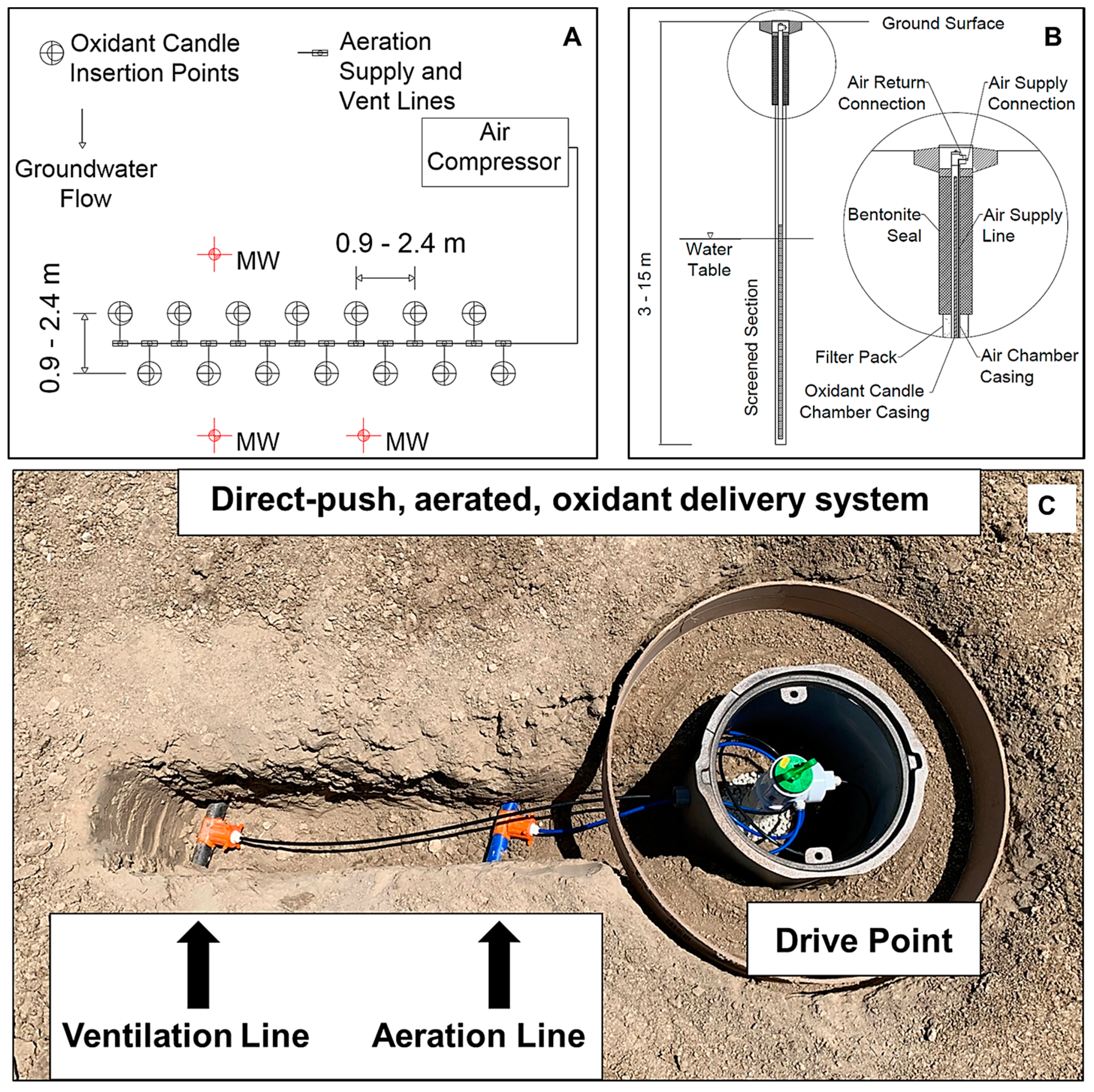
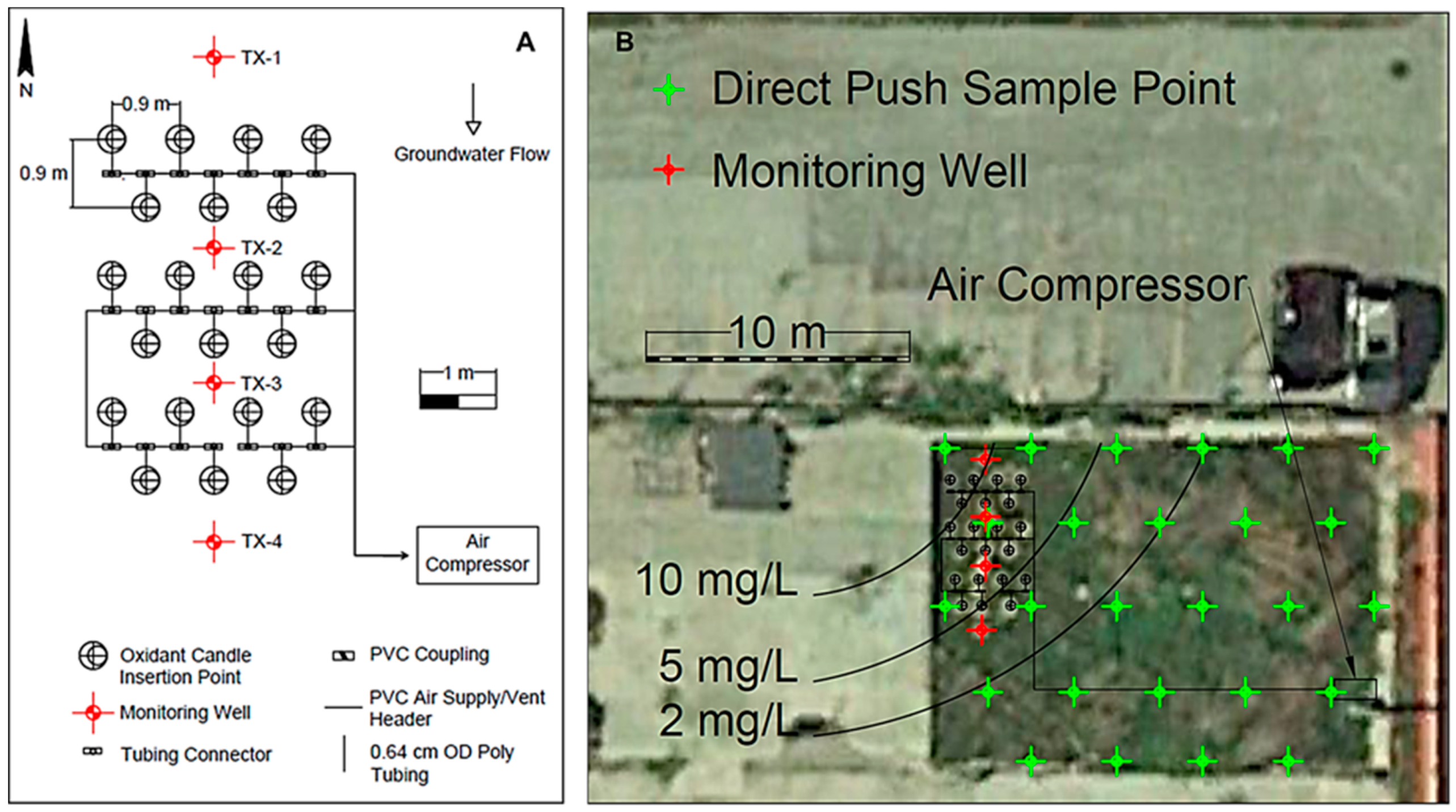
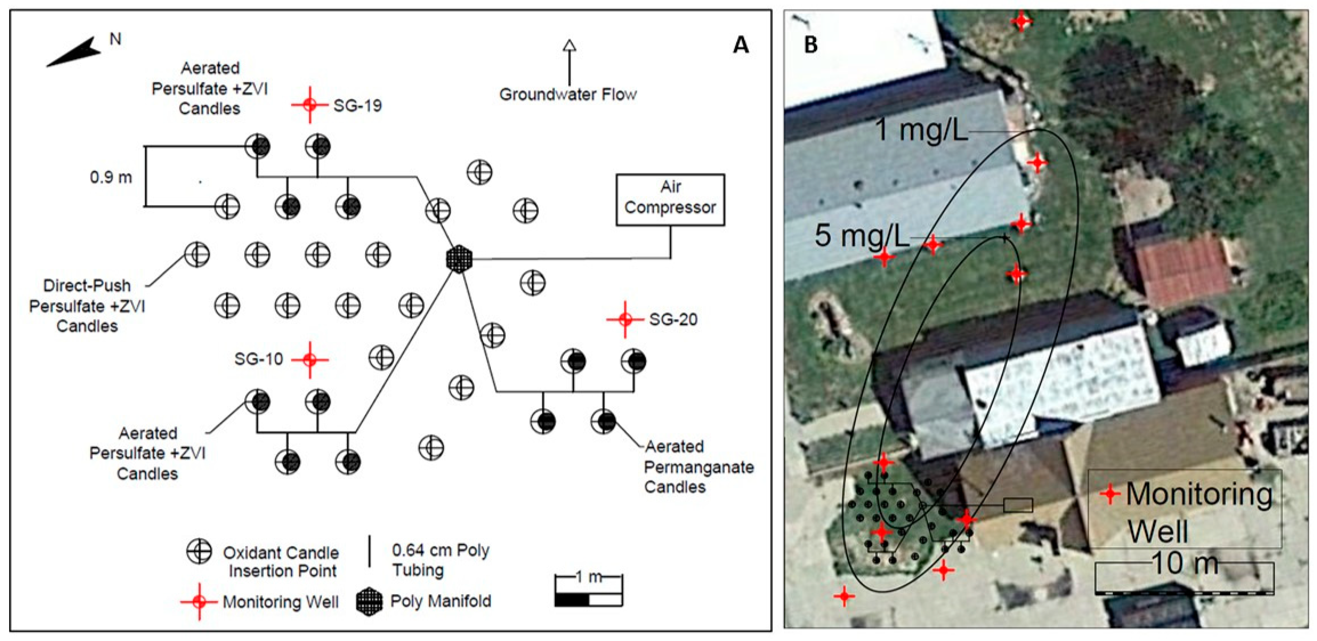
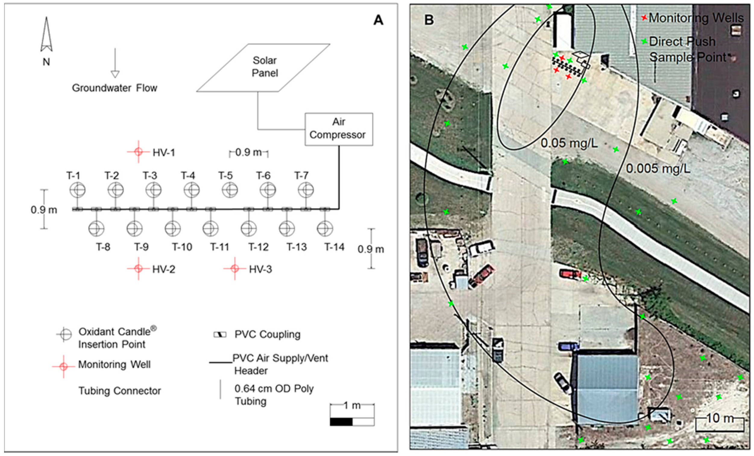
2.2. Generalized Plot Plan and Technology Components
2.3. Oxidant Delivery System
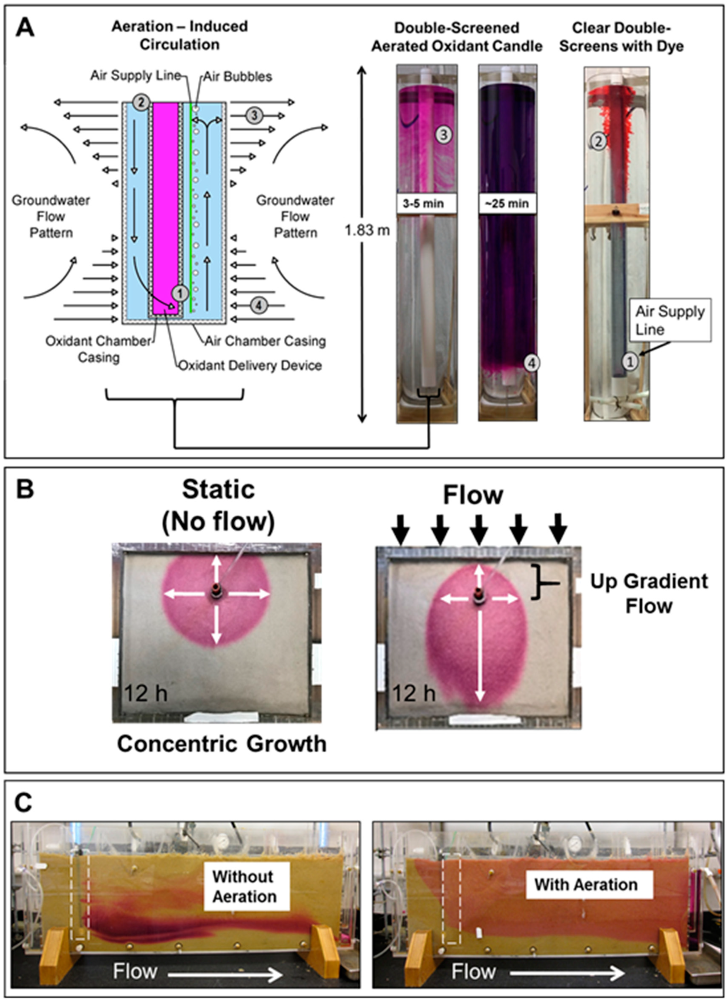
2.4. Visualizing Oxidant Dispersal from Aerated Oxidant Candles
2.5. Field Testing of Aerated, Direct-Push, Oxidant Candles
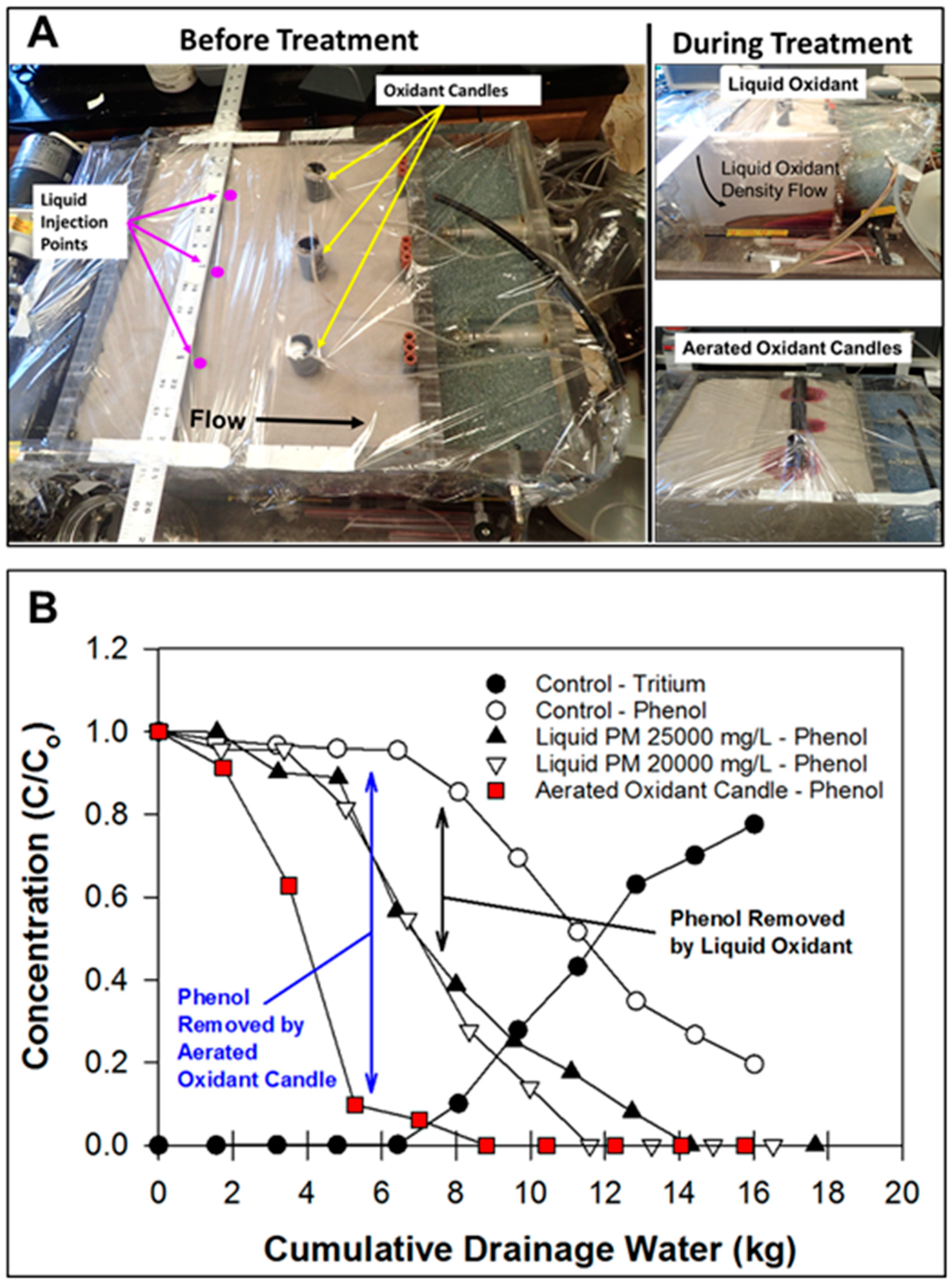
2.6. ISCO with Liquid Oxidant versus Aerated Oxidant Candle
3. Results and Discussion
3.1. Visualizing Oxidant Dispersal from Aerated Oxidant Candles
3.2. Field Testing of Aerated, Direct-Push, Oxidant Candles
3.3. Freeman Site
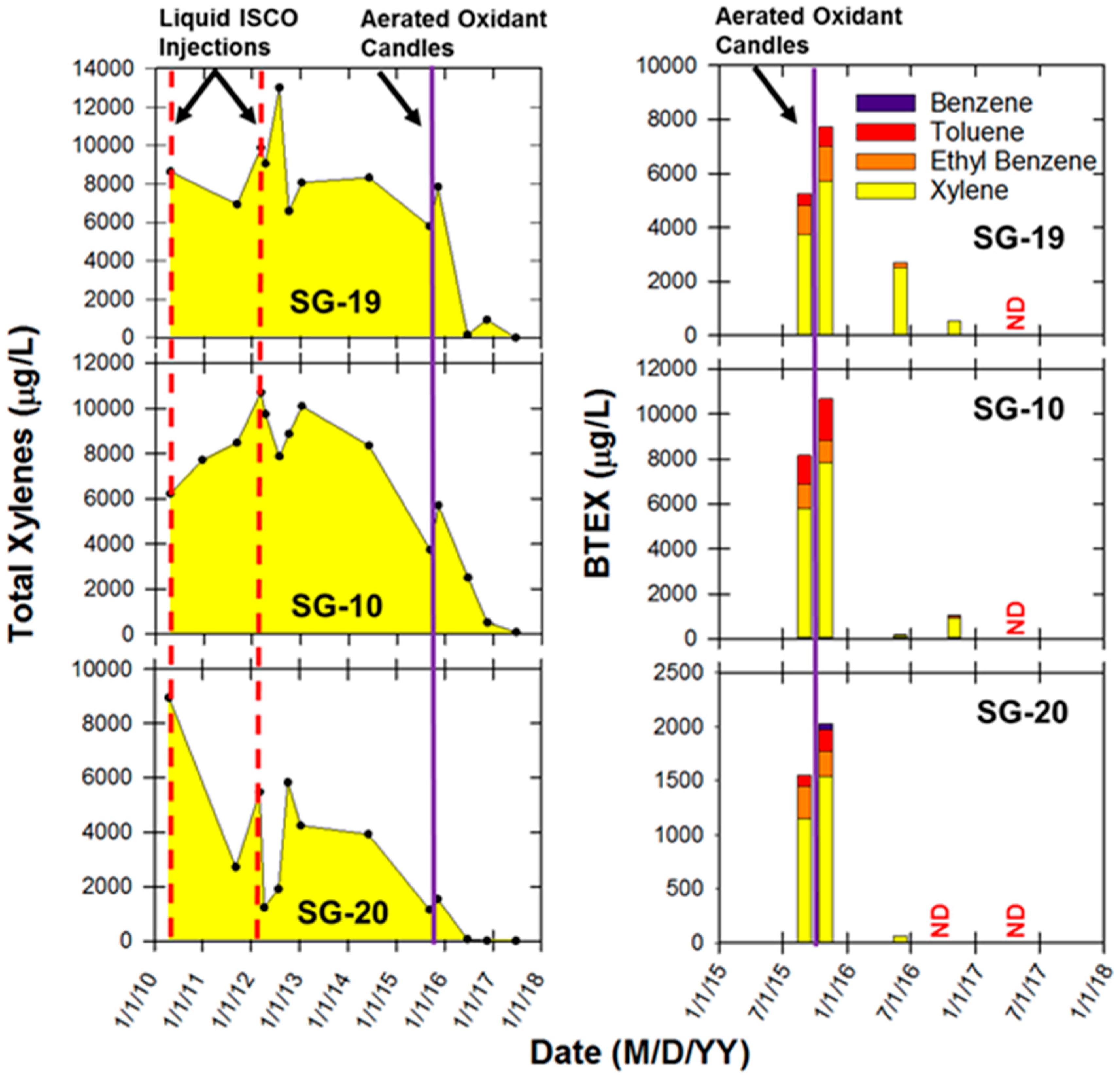
3.4. ISCO with the Liquid Oxidant versus Aerated Oxidant Candle
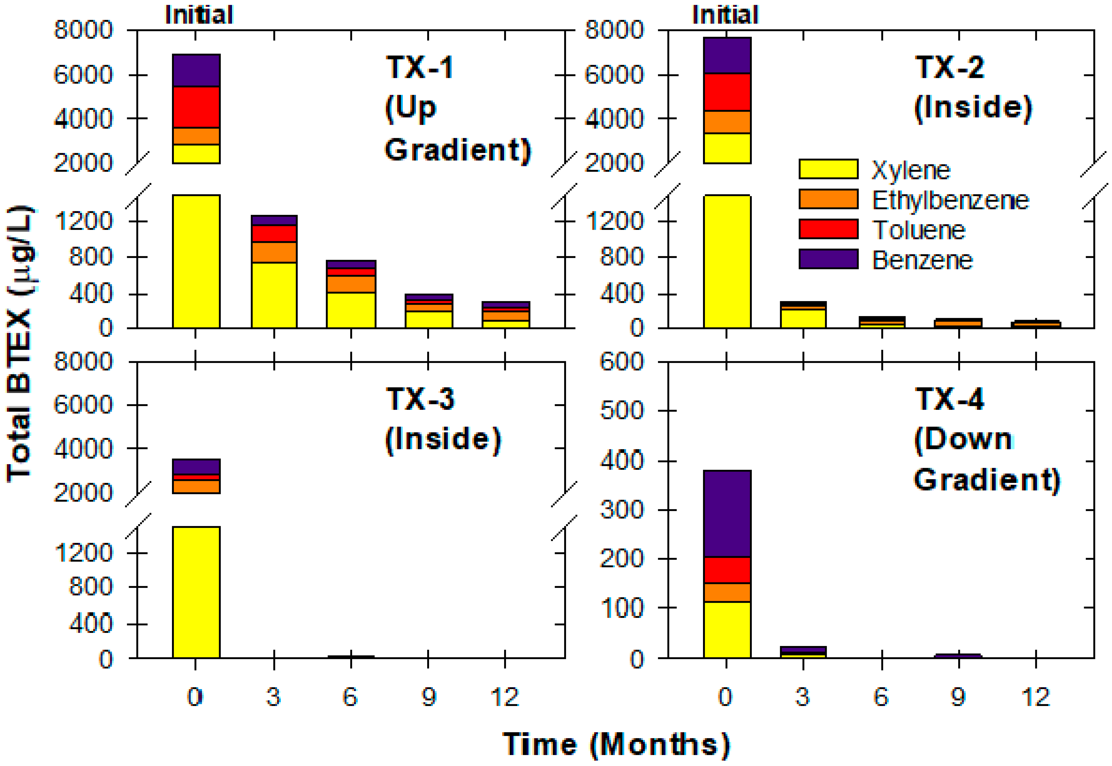
3.5. Textron Site
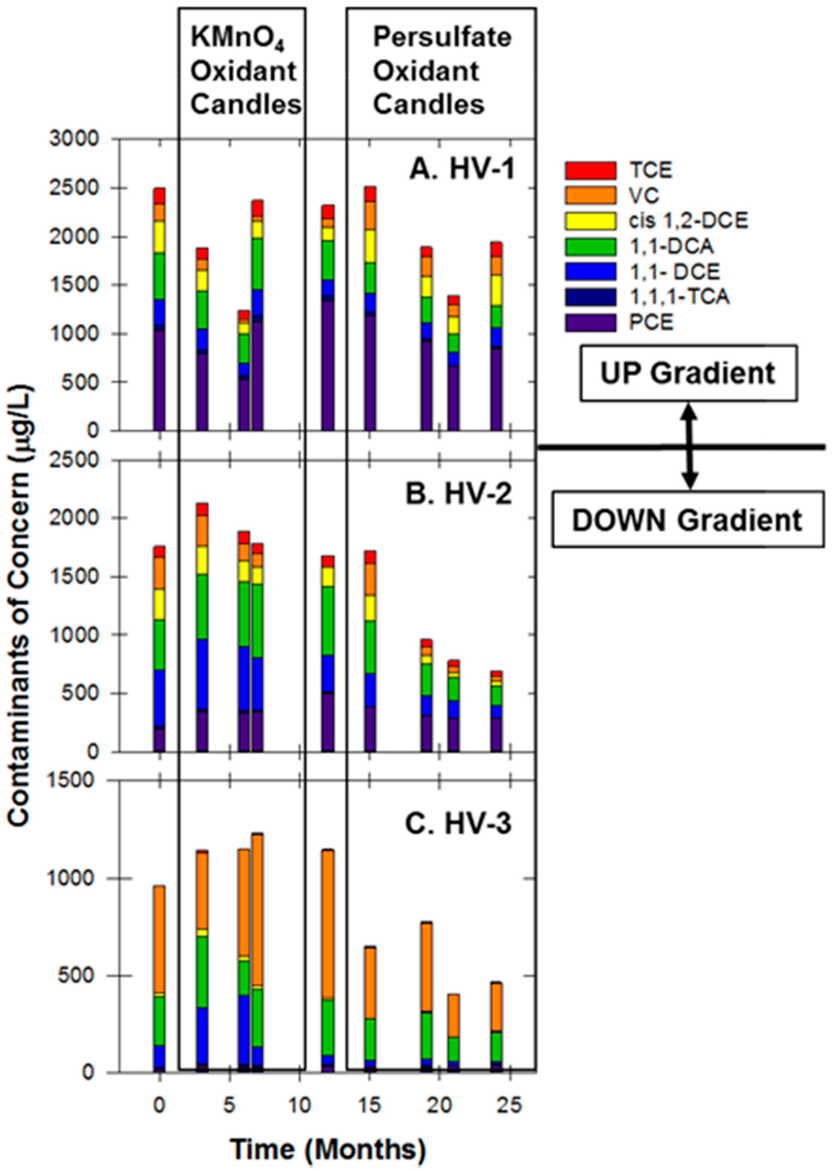
3.6. Hoover Site
4. Conclusions
5. Patents
Supplementary Materials
Author Contributions
Funding
Acknowledgments
Conflicts of Interest
References
- Huling, S.G.; Ross, R.R.; Prestbo, K.M. In situ chemical oxidation: Permanganate oxidant volume design considerations. Groundw. Monit. Remediat. 2017, 37, 78–86. [Google Scholar] [CrossRef]
- Suthersan, S.; McDonough, J.; Schnobrich, M.; Divine, C. In situ chemical treatment: A love-the relationship. Groundw. Monit. Remediat. 2017, 37, 17–26. [Google Scholar] [CrossRef]
- Krembs, F.J.; Siegrist, R.L.; Crimi, M.L.; Furrer, R.F.; Petri, B.G. ISCO for groundwater remediation: Analysis of field applications and performance. Groundw. Monit. Remediat. 2010, 30, 42–53. [Google Scholar] [CrossRef]
- PERF. Performance Evaluation of In situ Chemical Oxidation of Petroleum Impacts in Soil and Groundwater; Petroleum Environmental Research Forum (PERF) Project 2009-01; ExxonMobil: Irving, TX, USA, 2013. [Google Scholar]
- Liu, C.X.; Ball, W.P. Back diffusion of chlorinated solvent contaminants from a natural aquitard to a remediated aquifer under well-controlled field conditions: Predictions and measurements. Groundwater 2002, 40, 175–184. [Google Scholar] [CrossRef]
- Mundle, K.; Reynolds, D.A.; West, M.R.; Kueper, B.H. Concentration rebound following in situ chemical oxidation in fractured clay. Groundwater 2007, 45, 692–702. [Google Scholar] [CrossRef]
- McGuire, T.M.; McDade, J.M.; Newell, C.J. Performance of DNAPL source depletion technologies at 59 chlorinated solvent-impacted sites. Groundw. Monit. Remediat. 2006, 26, 73–84. [Google Scholar] [CrossRef]
- Kang, N.; Hua, I.; Rao, P.S. Production and characterization of encapsulated potassium permanganate for sustained release as an in situ oxidant. Ind. Eng. Chem. Res. 2004, 43, 5187–5193. [Google Scholar] [CrossRef]
- Ross, C.; Murdoch, L.C.; Freedman, D.L.; Siegrist, R.L. Characteristics of potassium permanganate encapsulated in polymer. J. Environ. Eng. 2005, 131, 1203–1211. [Google Scholar] [CrossRef]
- Schwartz, F.W. Semi-Passive, Chemical Oxidation Schemes for the Long-Term Treatment of Contaminants; The Ohio State University: Columbus, OH, USA, 2005. [Google Scholar]
- Lee, E.S.; Schwartz, F.W. Characteristics and applications of controlled-release KMnO4 for groundwater remediation. Chemosphere 2007, 66, 2058–2066. [Google Scholar] [CrossRef]
- Lee, E.S.; Schwartz, F.W. Characterization and optimization of long-term controlled release system for groundwater remediation: A generalized modeling approach. Chemosphere 2007, 69, 247–253. [Google Scholar] [CrossRef]
- Lee, E.S.; Liu, G.M.; Schwartz, F.W.; Kim, Y.J.; Ibaraki, M. Model-based evaluation of controlled-release systems in the remediation of dissolved plumes in groundwater. Chemosphere 2008, 72, 165–173. [Google Scholar] [CrossRef] [PubMed]
- Lee, E.S.; Woo, N.C.; Schwartz, F.W.; Lee, B.S.; Lee, K.C.; Woo, M.H.; Kim, J.H.; Kim, H.K. Characterization of controlled release KMnO4 (CRP) barrier system for groundwater remediation: A pilot-scale flow-tank study. Chemosphere 2008, 71, 902–910. [Google Scholar] [CrossRef] [PubMed]
- Lee, B.S.; Kim, J.H.; Lee, K.C.; Bin Kim, Y.; Schwartz, F.W.; Lee, E.S.; Woo, N.C.; Lee, M.K. Efficacy of controlled-release KMnO4 (CRP) for controlling dissolved TCE plume in groundwater: A large flow-tank study. Chemosphere 2009, 74, 745–750. [Google Scholar] [CrossRef]
- Swearingen, J.; Swearingen, L. Encapsulated Reactant and Process. U.S. Patent No. US 7,431,849 B1, 7 October 2008. [Google Scholar]
- Kambhu, A.; Comfort, S.; Chokejaroenrat, C.; Chainarong, C. Developing slow-release persulfate candles to treat BTEX contaminated water. Chemosphere 2012, 89, 656–664. [Google Scholar] [CrossRef] [PubMed] [Green Version]
- Rauscher, L.; Sakulthaew, C.; Comfort, S. Using slow-release permanganate candles to remediate PAH-contaminated water. J. Hazard. Mater. 2012, 241–242, 441–449. [Google Scholar] [CrossRef] [PubMed] [Green Version]
- Yuan, B.L.; Li, F.; Chen, Y.; Fu, M.-L. Laboratory-scale column study for remediation of TCE-contaminated aquifers using three-section controlled-release potassium permanganate barriers. J. Environ. Sci. 2013, 25, 971–977. [Google Scholar] [CrossRef]
- Liang, S.H.; Chen, K.F.; Wu, C.S.; Lin, Y.H.; Kao, C.M. Development of KMnO4-releasing composites for in situ chemical oxidation of TCE-contaminated groundwater. Water Res. 2014, 54, 149–159. [Google Scholar] [CrossRef] [PubMed]
- Kambhu, A.; Gren, M.; Tang, W.; Comfort, S.; Harris, C. Remediating 1,4-dioxane-contaminated water with slow-release persulfate and zerovalent iron. Chemosphere 2017, 175, 170–177. [Google Scholar] [CrossRef] [Green Version]
- Angkaew, A.; Sakulthaew, C.; Santapanajaur, T.; Poapolathep, A.; Chokejaroenrat, C. UV-activated persulfate oxidation of 17β-estradiol: Implications for discharge water remediation. J. Environ. Chem. Eng. 2019, 7, 102858. [Google Scholar] [CrossRef]
- Ma, Y.; Feng, Y.; Feng, Y.; Liao, G.; Sun, Y.; Ma, J. Characteristics and mechanisms of controlled-release KMnO4 for groundwater remediation: Experimental and modeling investigation. Water Res. 2020, 171, 115385. [Google Scholar] [CrossRef]
- O’Connor, D.; Hou, D.; Ok, Y.S.; Song, Y.; Sarmah, A.K.; Li, X. Sustainable in situ remediation of recalcitrant organic pollutants in groundwater with controlled release materials: A review. J. Control. Release 2018, 283, 200–213. [Google Scholar] [CrossRef]
- Christenson, M.; Kambhu, A.; Comfort, S.D. Using slow-release permanganate candles to remove TCE from a low permeable aquifer at a former landfill. Chemosphere 2012, 89, 680–687. [Google Scholar] [CrossRef] [Green Version]
- Kambhu, A.; Li, Y.; Gilmore, T.; Comfort, S. Modeling the Release and Spreading of Permanganate from Aerated Slow-Release Oxidants in a Laboratory Flow Tank. J. Hazard. Mater. 2021, 403, 123719. [Google Scholar] [CrossRef]
- Christenson, M.; Kambhu, A.; Reece, J.; Comfort, S.D.; Brunner, L. A five-year performance review of field-scale, slow-release permanganate candles with recommendations for second-generation improvements. Chemosphere 2016, 150, 239–247. [Google Scholar] [CrossRef] [Green Version]
- Christenson, M.; Comfort, S.D. Modular Oxidant Delivery System. U.S. Patent No. US 9,925,574 B2, 27 March 2018. [Google Scholar]
- Yoshinaga, T.; Sato, Y. Performance of an air-lift pump for conveying coarse particles. Int. J. Multiph. Flow 1996, 22, 223–238. [Google Scholar] [CrossRef]
- Hanafizadeh, P.; Ghorbani, B. Review study on airlift pumping systems. Multiph. Sci. Technol. 2012, 24, 323–362. [Google Scholar] [CrossRef]
- Kambhu, A. Treating 1,4-Dioxane with Slow-Release Persulfate and Zerovalent Iron and Modeling the Radius of Influence of Aerated Oxidant Candles. Ph.D. Thesis, University of Nebraska, Lincoln, NE, USA, 2019. [Google Scholar]
- Kolthoff, I.M.; Miller, I.K. The chemistry of persulfate: I. The kinetics and mechanism of the decomposition of the persulfate ion in aqueous medium. J. Am. Chem. Soc. 1951, 73, 3055–3059. [Google Scholar] [CrossRef]
- Dash, S.; Patel, S.; Mishra, B.K. Oxidation by permanganate: Synthetic and mechanistic aspects. Tetrahedron 2009, 65, 707–739. [Google Scholar] [CrossRef]
- Huang, K.-C.; Hoag, G.E.; Chheda, P.; Woody, B.A.; Dobbs, G.M. Kinetics and mechanism of oxidation of tetrachloroethylene with permanganate. Chemosphere 2002, 46, 815–825. [Google Scholar] [CrossRef]
- Huang, K.-C.; Zhao, Z.; Hoag, G.E.; Dahmani, A.; Block, P.A. Degradation of volatile organic compounds with thermally activated persulfate oxidation. Chemosphere 2005, 61, 551–560. [Google Scholar] [CrossRef]
- Mahmoodlu, M.G.; Hassanizadeh, S.M.; Hartog, N. Evaluation of the kinetic oxidation of aqueous volatile organic compounds by permanganate. Sci. Total Environ. 2014, 485–486, 755–763. [Google Scholar] [CrossRef]
- Lee, D.G.; Chen, T. Oxidation of hydrocarbons. 18. Mechanism of the reaction between permanganate and carbon-carbon double bonds. J. Am. Chem. Soc. 1989, 111, 7534–7538. [Google Scholar] [CrossRef]
- Yan, Y.E.; Schwartz, F.W. Oxidative degradation and kinetics of chlorinated ethylenes by potassium permanganate. J. Contam. Hydrol. 1999, 37, 343–365. [Google Scholar] [CrossRef]
- Yan, Y.E.; Schwartz, F.W. Kinetics and mechanism for TCE oxidation by permanganate. Environ. Sci. Technol. 2000, 34, 2535–2541. [Google Scholar] [CrossRef]
- Woo, N.C.; Hyun, S.G.; Park, W.W.; Lee, E.S.; Schwartz, F.W. Characteristics of permanganate oxidation of TCE at low reagent concentrations. Environ. Technol. 2009, 30, 1337–1342. [Google Scholar] [CrossRef]
- Crimi, M.L.; Taylor, J. Experimental evaluation of catalyzed hydrogen peroxide and sodium persulfate for destruction of BTEX contaminants. Soil Sediment Contam. 2007, 16, 29–45. [Google Scholar] [CrossRef]
- Killian, P.F.; Bruell, C.J.; Liang, C.; Marley, M.C. Iron (II) activated persulfate oxidation of MGP contaminated soil. Soil Sediment Contam. 2007, 16, 523–537. [Google Scholar] [CrossRef]
- Liang, C.; Huang, C.F.; Chen, Y.J. Potential for activated persulfate degradation of BTEX contamination. Water Res. 2008, 42, 4091–4100. [Google Scholar] [CrossRef]
- Achugasim, D.; Osuji, L.C.; Ojinnaka, C.M. Use of activated persulfate in the removal of petroleum hydrocarbons from crude oil polluted soils. Res. J. Chem. Sci. 2011, 1, 57–67. [Google Scholar]
- Lemaire, J.; Croze, V.; Maier, J.; Simonnot, M. Is it possible to remediate a BTEX contaminated chalky aquifer by in situ chemical oxidation? Chemosphere 2011, 84, 1181–1187. [Google Scholar] [CrossRef]
- Agency for Toxic Substances and Disease Registry (ATSDR). Toxicological Profile for Acetone. U.S. Department of Health and Human Services. 1994. Available online: https://www.atsdr.cdc.gov/substances/toxsubstance.asp?toxid=1 (accessed on 8 January 2020).
- Wiberg, K.B.; Geer, R.D. The kinetics of the permanganate oxidation of acetone. J. Am. Chem. Soc. 1965, 87, 5202–5209. [Google Scholar] [CrossRef]
- Harcourt, A.V.; Esson, W. On the laws of connexion between the Conditions of a Chemical Change and Its Amount. Philos. Trans. R. Soc. Lond. 1866, 156, 193–221. [Google Scholar] [CrossRef] [Green Version]
- Gates-Anderson, D.D.; Siegrist, R.L.; Cline, S.R. Comparison of potassium permanganate and hydrogen peroxide as chemical oxidants for organically contaminated soils. J. Environ. Eng. 2001, 127, 337–347. [Google Scholar] [CrossRef]
- Chokejaroenrat, C.; Comfort, S.D.; Harris, C.; Snow, D.; Cassada, D.; Sakulthaew, C.; Satapanajaru, T. Transformation of Hexahydro-1,3,5-trinitro-1,3,5-triazine (RDX) by permanganate. Environ. Sci. Technol. 2011, 45, 3643–3649. [Google Scholar] [CrossRef] [Green Version]
- Chokejaroenrat, C. Laboratory and Pilot-Scale Investigations of RDX Treatment by Permanganate. Master’s Thesis, University of Nebraska, Lincoln, NE, USA, 2008. [Google Scholar]
- Evans, P.J.; Dugan, P.; Nguyen, D.; Lamar, M.; Crimi, M. Slow-release permanganate versus unactivated persulfate for long-term in situ oxidation of 1,4-dioxane and chlorinated solvents. Chemosphere 2019, 221, 802–811. [Google Scholar] [CrossRef]
- Evans, P.; Hooper, J.; Larmar, M.; Nguyen, D.; Dugan, P.; Crimi, M.; Ruiz, N. Sustained In Situ Chemical Oxidation (ISCO) of 1,4-Dioxane and Chlorinated VOCs Using Slow-Release Chemical Oxidant Cylinders; Environmental Security Technology Certification Program (ESTCP) Cost and Performance Report (ER-201324); Environmental Security Technology Certification Program (ESTCP): Alexandria, VA, USA, July 2018; p. 73.
- Chokejaroenrat, C.; Negin, K.; Sakulthaew, C.; Comfort, S.; Li, Y. Improving the sweeping efficiency of permanganate into low permeable zones to treat TCE: Experimental results and model development. Environ. Sci. Technol. 2013, 47, 13031–13038. [Google Scholar] [CrossRef] [Green Version]


| Site Characteristics | Freeman | Textron | Hoover |
|---|---|---|---|
| Treatment type | Source Zone | Source Zone | Permeable Reactive Barrier |
| Depth to Groundwater (m) | 2.0 | 4.1 | 4.4 |
| Screened Interval of Oxidant Drive Points (m) | 1.5–6.1 | 1.5–6.1 | 1.5–6.4 |
| Screened Interval of Monitoring wells (m) | 1.2–4.3 | 1.5–6.1 | 3.4–6.4 |
| Texture | Layers of Clay and Fine to Coarse Sand | Layers of Clay, Sandy Clay, and Medium to Fine Sand | Lean Clay with various amounts of Fine Sands |
| Seepage Velocity (cm/day) | 16.5 | 26.5 | 0.21 |
| Contaminant(s) of Concern | BTEX | BTEX | 1,4-dioxane, TCE, BTEX |
| Dissolved Oxygen (mg/L) Initial Range 1 | 0.76–1.64 | 0.34–3.30 | 0.32–1.80 |
| ORP (mV) Initial Range | −248.6 to −207.1 | −118.9 to 48.0 | −167.4 to −48.5 |
| pH Initial Range | 6.45–6.78 | 6.15–6.98 | 6.47–7.06 |
Publisher’s Note: MDPI stays neutral with regard to jurisdictional claims in published maps and institutional affiliations. |
© 2020 by the authors. Licensee MDPI, Basel, Switzerland. This article is an open access article distributed under the terms and conditions of the Creative Commons Attribution (CC BY) license (http://creativecommons.org/licenses/by/4.0/).
Share and Cite
Reece, J.; Christenson, M.; Kambhu, A.; Li, Y.; Harris, C.E.; Comfort, S. Remediating Contaminated Groundwater with an Aerated, Direct-Push, Oxidant Delivery System. Water 2020, 12, 3383. https://doi.org/10.3390/w12123383
Reece J, Christenson M, Kambhu A, Li Y, Harris CE, Comfort S. Remediating Contaminated Groundwater with an Aerated, Direct-Push, Oxidant Delivery System. Water. 2020; 12(12):3383. https://doi.org/10.3390/w12123383
Chicago/Turabian StyleReece, James, Mark Christenson, Ann Kambhu, Yusong Li, Clifford E. Harris, and Steve Comfort. 2020. "Remediating Contaminated Groundwater with an Aerated, Direct-Push, Oxidant Delivery System" Water 12, no. 12: 3383. https://doi.org/10.3390/w12123383
APA StyleReece, J., Christenson, M., Kambhu, A., Li, Y., Harris, C. E., & Comfort, S. (2020). Remediating Contaminated Groundwater with an Aerated, Direct-Push, Oxidant Delivery System. Water, 12(12), 3383. https://doi.org/10.3390/w12123383