Article

Analysing the Near-Field Effects and the Power Production of Near-Shore WEC Array Using a New Wave-to-Wire Model

Department of Civil Engineering, Ghent University, Technologiepark 60, B-9052 Ghent, Belgium
*
Author to whom correspondence should be addressed.
Water 2019, 11(6), 1137; https://doi.org/10.3390/w11061137
Submission received: 1 May 2019 / Revised: 22 May 2019 / Accepted: 23 May 2019 / Published: 30 May 2019

Abstract

:
In this study, a series of modules is integrated into a wave-to-wire (W2W) model that links a Boundary Element Method (BEM) solver to a Wave Energy Converter (WEC) motion solver which are in turn coupled to a wave propagation model. The hydrodynamics of the WECs are resolved in the wave structure interaction solver NEMOH, the Power Take-off (PTO) is simulated in the WEC simulation tool WEC-Sim, and the resulting perturbed wave field is coupled to the mild-slope propagation model MILDwave. The W2W model is run for verified for a realistic wave energy project consisting of a WEC farm composed of 10 5-WEC arrays of Oscillating Surging Wave Energy Converters (OSWECs). The investigated WEC farm is modelled for a real wave climate and a sloping bathymetry based on a proposed OSWEC array project off the coast of Bretagne, France. Each WEC array is arranged in a power-maximizing 2-row configuration that also minimizes the inter-array separation distance d x and d y and the arrays are located in a staggered energy maximizing configuration that also decreases the along-shore WEC farm extent. The WEC farm power output and the near and far-field effects are simulated for irregular waves with various significant wave heights wave peak periods and mean wave incidence directions β based on the modelled site wave climatology. The PTO system of each WEC in each farm is modelled as a closed-circuit hydraulic PTO system optimized for each set of incident wave conditions, mimicking the proposed site technology, namely the WaveRoller® OSWEC developed by AW Energy Ltd. The investigation in this study provides a proof of concept of the proposed W2W model in investigating potential commercial WEC projects.

1. Introduction

In [1], the development of various numerical tools was witnessed and diverse facets of the WEC array problem were investigated, specifically the complex interplay between the WEC array power and the WEC array effects on the surrounding area. One is now able to pull together the various developments, including:
  • coupling between the BEM solver NEMOH and the mild-slope wave propagation model MILDwave,
  • development of an iterative technique to model WEC Farms composed of clustered WEC arrays,
  • development of a realistic time-domain Power Take-off (PTO) module.
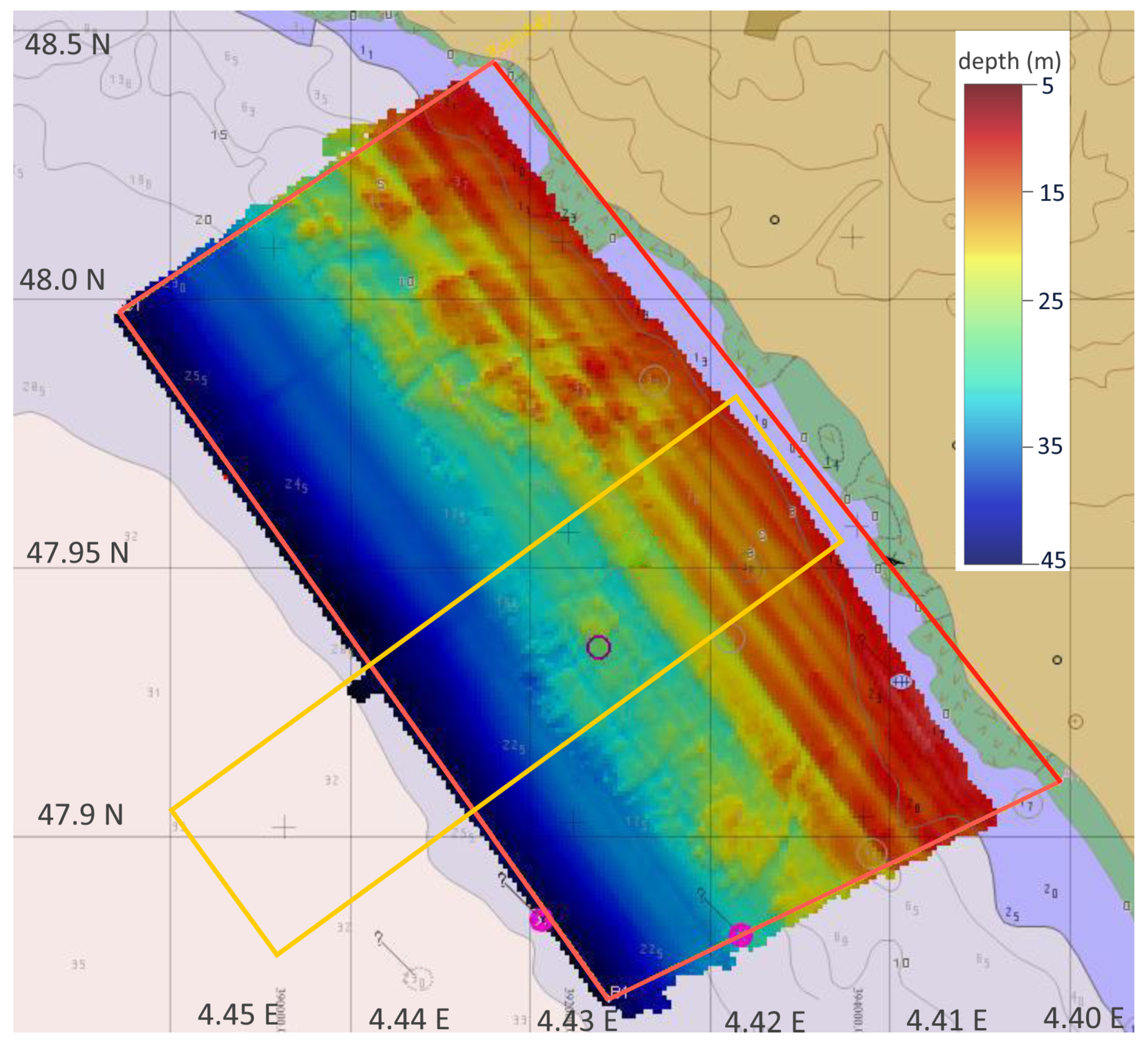
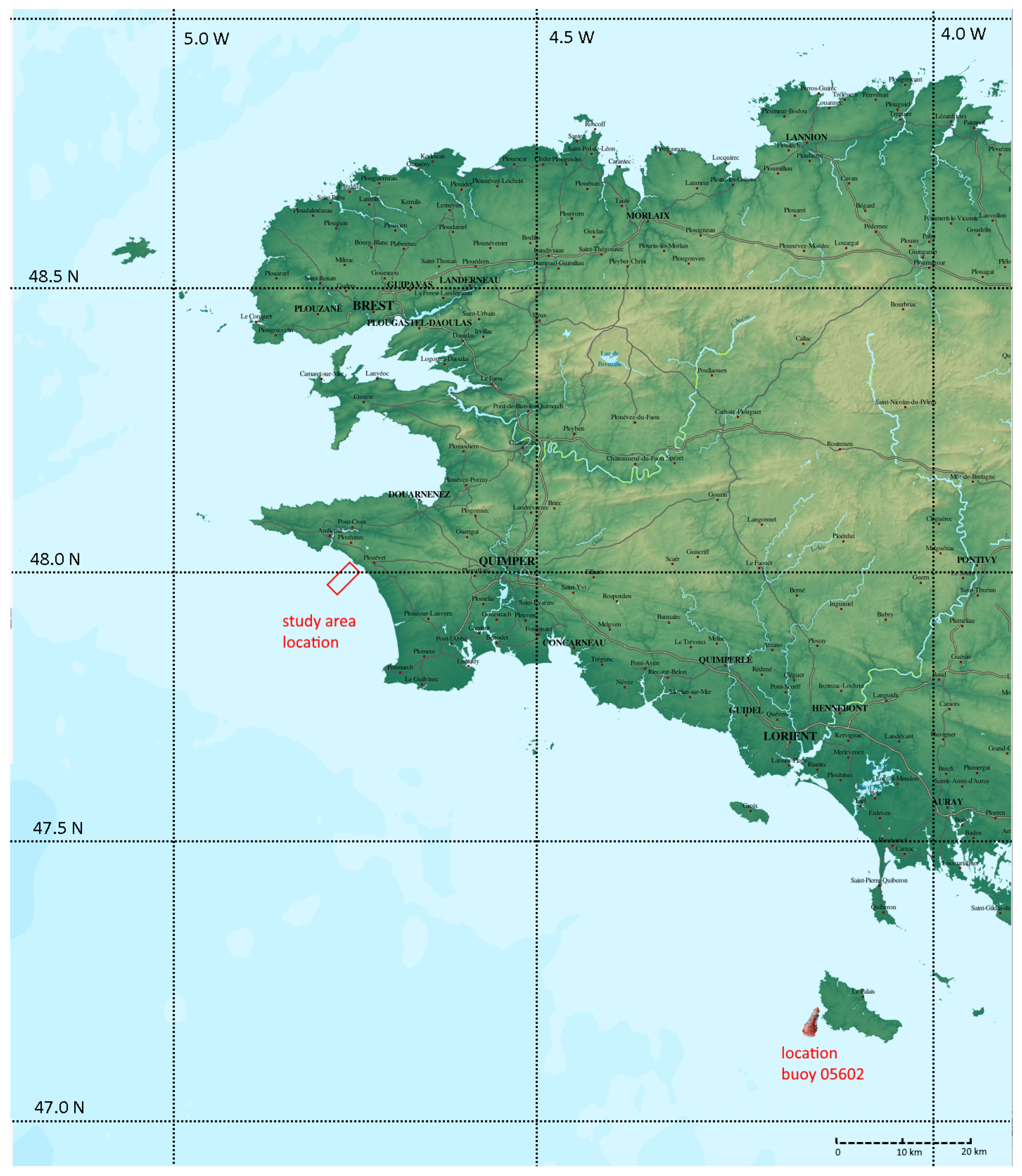
Unlike existing wave-to-wire models such as [2,3], which focus on a specific Wave Energy Converter (WEC) technology, or those such as [4,5] that deal with a single objective of power maximization, the model proposed in this study has the dual goal of (i), accurately representing the wave field around the array and (ii), allowing a fast and accurate calculation of the power output of a given WEC array project. In this study, the W2W model introduced in the bullet points above is tested for a realistic scenario of a proposed commercial WEC array project. The WATTMOR proposal developed by the energy companies DCNS and Fortum in partnership with the Finnish company AW Energy is modelled utilizing the WaveRoller® technology [6]. WaveRoller is an OSWEC (Oscillating Surging Wave Energy Converter) that has been successfully deployed over various generations and independently certified by the ratings agency Lloyd’s register [7]. The WEC farm investigated in this study is to be located in the Baie d’Audierne near Pouldreuzic in Bretagne, France at a latitude of 47.93 ° N and a longitude of 4 ° 44 W. The project location is shown in Figure 1 on a map of the western part of the Finistère peninsula of Bretagne.
The realistic deployment scenario consists of modelling the following four WEC array project aspects:
  • a wave climate representative of that observed at the installation site,
  • a realistic sloping bathymetry,
  • a WEC with approximate dimensions to the WEC technology that is to be deployed,
  • a hydraulic PTO system simulating that of the proposed WEC,
  • a WEC farm layout that seeks to maximize power absorption over a limited coastal length.
The wave climate utilized by the model is derived from nine years of actual buoy data from the French buoy network provided by CANDHIS (Centre d’Archivage National des Données de Houle In Situ) [8]. The site bathymetry, based on surveys carried out for the WATTMOR project, as shown in Figure 3, is approximated in this study by a slope of 1/200 which easily fits within the criteria for the application of MILDwave as detailed in [9,10]. The modelled OSWEC has dimensions equal to those of the OSWEC investigated in [11] and is based on the publicly available information on the WaveRoller® technology. The PTO system is reproduced in WEC-Sim [12] as a simplified, yet accurate, hydraulic time-domain simulation which has been introduced in [1] and detailed in [11]. The WEC farm absolute value of the total free surface elevation | η | is determined via an iterative the method first developed in [1] and detailed in Section 2.8.
For a given WEC type and for a given incident wave, a critical parameter that influences the WEC motion and the power output of a WEC farm is the PTO system. Because of the variety of technical solutions and the complexity of modelling the inherently nonlinear behaviour of a majority of viable PTO systems in WECs, a plurality of previous investigations have assumed a simple mechanical damper as a proxy for the PTO system. Some examples for farms or arrays of heaving cylindrical WECs are found in [13,14,15,16,17,18,19] and for OSWECs in [12,20,21,22]. Concurrently, due to substantial improvements in hydrodynamic modelling software, there has been a jump in the number of numerical investigations that have modelled single WECs [23,24,25,26] and small farms of WECs [27,28] with fully nonlinear hydrodynamics. However, as mentioned in Penalba et al. [29], for the case of heaving cylindrical WECs and in Schmitt et al. [21] for OSWECs, the errors due to a simplified PTO model can override any improvements imparted by more accurate hydrodynamic models. A particular concern with many existing PTO modelling approaches is that the most common PTO system type developed for commercial WEC prototypes, a hydraulic PTO system, is inherently nonlinear [30,31,32]. A few recent studies, notably [29,30,32,33,34,35,36], have achieved realistic hydraulic PTO models with nonlinear dynamics. However, these investigations were limited in their scope to single WECs and not WEC arrays. Moreover, many of the models are quite complicated in their implementation and not universally applicable. Conversely, a number of recent studies that looked at the coastal impacts of near-shore WEC arrays [37,38,39] have utilized phase-averaged models which are not able to fully resolve WEC motions induced by PTO systems.
In this study, our aim is to implement an array of five OSWECs composed of devices with realistic hydraulic PTO system models. Although the terms “WEC farm” and “WEC array” are used interchangeably, the authors will follow the precedent set in [1] and term a small farm of closely-spaced WECs a WEC array. The PTO system is simulated using WEC-Sim [12], a dynamical simulator for WECs built in the Matlab Simulink platform (R2017b, MathWorks Inc., Natick, MA, USA). The PTO model is coupled to the open-source wave–structure interaction solver NEMOH [40] using the perturbed wave field extracted from the motion of the OSWECs in the dynamical solver WEC-Sim. Previously, a similar coupled model approach was presented in [9,41,42,43,44] for the case of a wave–structure interaction solver coupled to a wave propagation model using a basic linear PTO model. WEC-Sim has been utilized in modelling hydraulic PTOs in a number of recent studies [34,36]. In referencing the near-field, a reference is made to the area inside the WEC array immediately surrounding the WECs, while the far-field can refer to areas outside the immediate area of the WEC array up to several kilometres away. The modifications of the wave field in the presence of multiple bodies are referred to as ‘WEC array effects’, which are synonymous with ‘WEC farm’ or ‘park effects’ used in some literature [14,44,45,46,47]. The ‘intra-array’ effects which refer to the array effects between WECs inside an array are compared and contrasted with ‘inter-array’ effects that refer to those between disparate WEC arrays in a WEC farm. Results will be presented in two parts: firstly, a pilot-scale layout example of a 10-OSWEC farm consisting of two 5-OSWEC arrays placed on an shore-orthogonal axis in Section 4, and secondly the full-scale layout is presented consisting of a gridded 50-WEC farm of 10 5-WEC arrays in Section 5. The power output and the near- and far-field of the WEC farms will be presented for the seasonal wave conditions based in the wave data calculated in Section 1.3. For the full-scale layout, the power output will be analysed for spring, winter and summer wave conditions in Tables 5–7, respectively. In the discussion in Section 6, it will be commented on the interaction between the bathymetry and the wake effects of the WEC farm’s constituent arrays and on the influence of the wave conditions. Finally, in Section 7, a summary of the results of the study with a view toward assessing the coastal impacts of potential wave energy projects will be done, especially those located relatively close to the shore.

1.1. Study Location and Geographical Context

The proposed WEC farm investigated in this study is placed in the Baie d’Audierne near Pouldreuzic in Bretagne, France at a latitude of 47.93 ° N and a longitude of 4 ° 44 W in a region of gently sloping bathymetry close to major sea ports. The overview map showing the study area within the context of the surrounding region is shown in Figure 1. The W2W model domain chosen for this investigation, indicated by the yellow rectangle in Figure 2, overlaps the commercial project area shown in the red box in the same figure. The reasoning for considering an orthogonal numerical domain is that one is primarily interested in the transformation of the waves over the sloping bathymetry and its impact on the WEC array power production and the WEC array far-field effects on the coast. Furthermore, with the seaward boundary set at a 35 m water depth (see Section 1.2 for details), the incoming waves will be minimally affected by shoaling and thus can serve as a good proxy for the offshore wave incident wave.
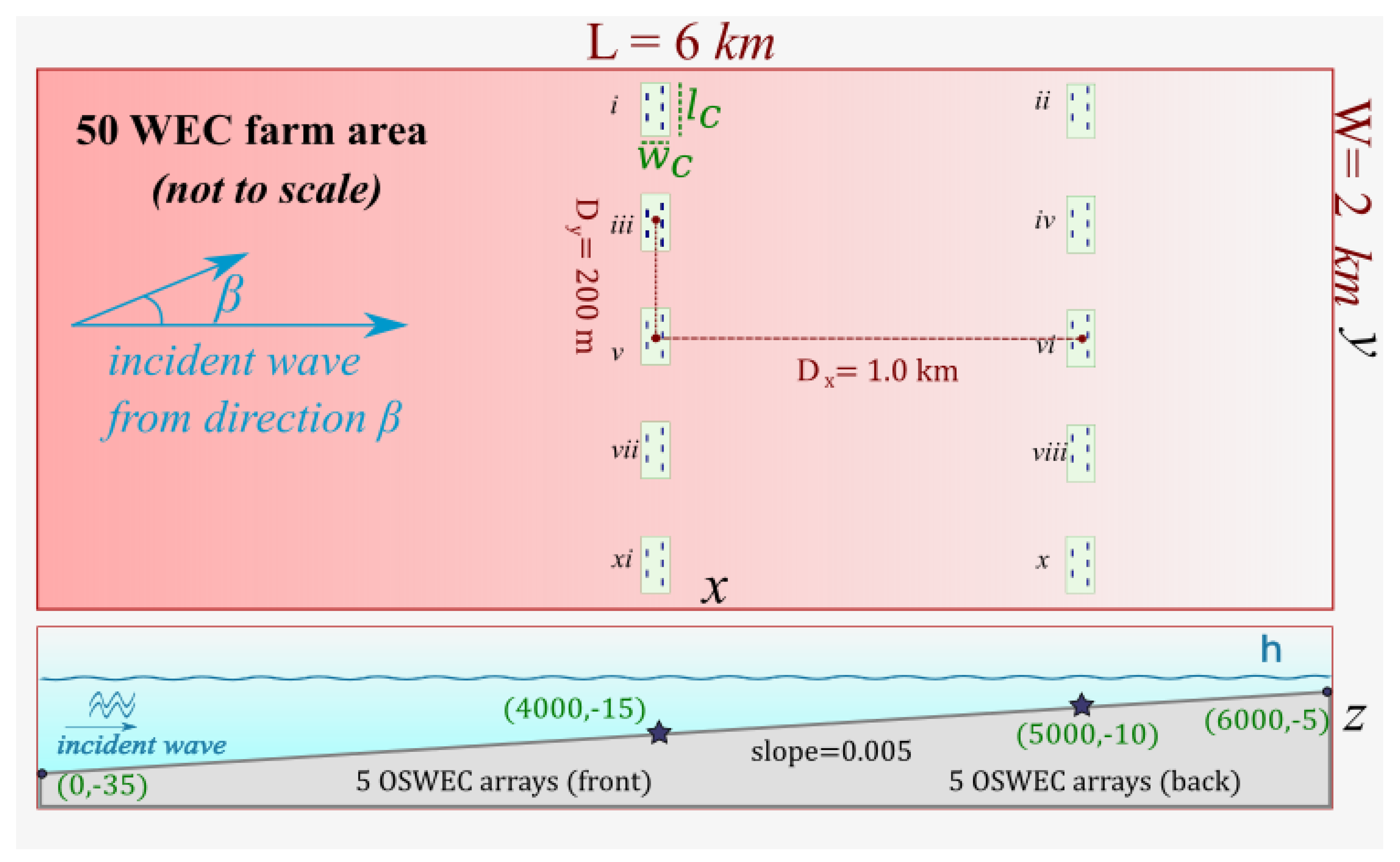
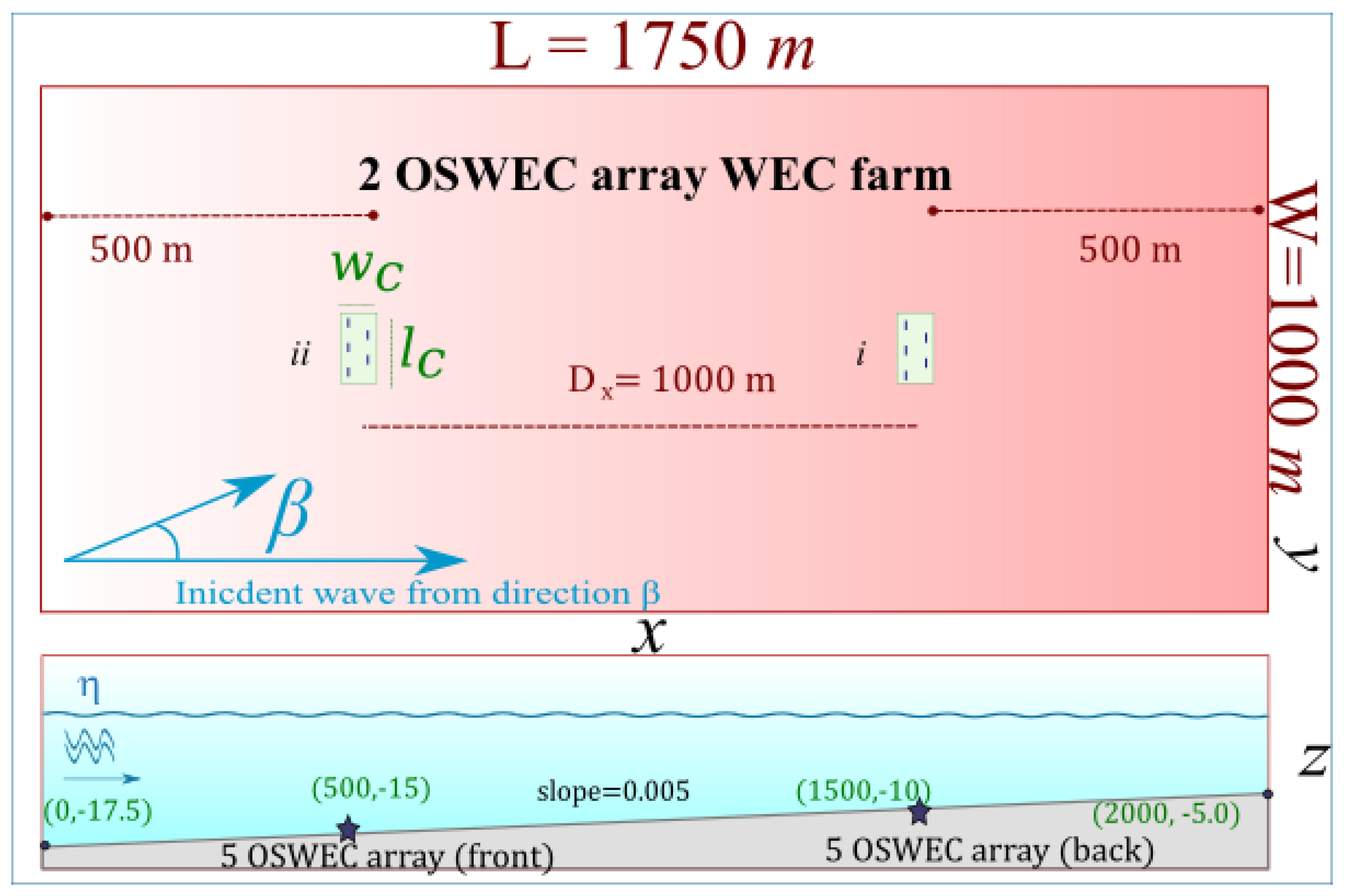
For the bathymetry given in Figure 3, The WEC farm layout and the sea bottom profile are shown in Figure 4. Note that the horizontal scale is shrunk for clarity. The individual rectangular WEC array domains modelled in NEMOH are shown as green, numbered i through x, where the first five numbered arrays are located in the wave-facing front row, in deeper water. The location for the hypothetical WEC farm investigated in this study was chosen for a number of reasons. Firstly, as mentioned in the introduction, the site currently under investigation for a possible commercial WEC array project, namely WATTMOR [6]. Secondly, the wave climate at the site is representative of the North Atlantic wave climate which covers the majority of the European coastline that is currently home to the largest number of existing and proposed WEC array projects [48]. Thirdly, the characteristics of the bathymetry, with a gentle slope and isobaths nearly parallel to the coastline, easily lend themselves to modelling by using a mild slope equation-based wave propagation model. Finally, at the given site, there is an energetic wave climate capable of supporting an economically viable wave energy conversion technology as will be detailed in Section 1.3. There is a strong match between the chosen OSWEC operating conditions and the mean wave climate [6]. Geographically, the site is in close proximity to large ports such as Brest, Douarnenez and Quimper, which are able to provide the necessary access and know-how for the deployment and maintenance of a WEC array project. Lastly, the location of a wave measuring buoy with a high resolution long-term recording history approximately 100 km off the coast enables us to utilize real wave data in our modelling.

1.2. Site Bathymetry and Approximation

The site bathymetry is presented in Figure 2 and Figure 3, with the latter giving the high resolution survey data specifically collected for the WATTMOR project. As one observes in Figure 3, the chosen model domain is very well approximated by a shore-orthogonal slope, with only a few variations that are well within the margin of the relevant approximation. Moreover, the site sea bottom consists of mostly fine sand which tends to shift in response to the waves and currents; therefore, a slope is also the most accurate representation of the average bathymetric profile over a WEC Array project lifetime of several decades.

1.3. Analysis of the Wave Climate at the Investigation Site

The proposed WEC array project location lies 100 km away from the nearest long-term wave measuring buoy with an interrupted data record. The station 05602–Belle-île is maintained by the Centre d’Archivage National de Données de Houle In Situ (CANDHIS), which is a partnership between the Grand Port Maritime de Nantes St-Nazaire, l’École Centrale de Nantes, and the French public agency CEREMA (Centre d’études et d’expertise sur les risques, l’environnement, la mobilité et l’aménagement). The location of the measuring buoy and the investigation area of this study are shown in Figure 1.
The wave rider buoy, located at 47 ° 17.1 N and 3 ° 17.1 W, has been providing continuous half-hourly directional wave data since its deployment in 2010. In this investigation, the investigation utilizes nine years of data from December of 2010 to March of 2019. Of the measurements provided by the wave rider buoy, this study has utilized the spectrally-derived significant wave height, H m 0 , the peak wave period T p , and the mean wave direction from true North, θ m , which will be utilized to derive the incoming wave direction β relative to the shore-orthogonal rectangular WEC farm domain axis (shown in yellow in Figure 2). The wave data is analysed and split into four seasonal bins, namely winter, spring, summer, and autumn, based on meteorological convention, i.e., winter is “Dec–Feb”. The bulk average of the aforementioned quantities is given in Table 1 along with the overall 9-year averages.
There are a few evident trends one can note from the table. Firstly, this is a relatively energetic sea state without a significant inter-year variation in the three major parameters, namely, H m 0 , T p , and θ m . The mean winter H m 0 and T p are significantly higher than the summer values. One also notices the small divergence between the spring and autumn values, with only a 4% difference in H m 0 , less than 1% difference in the T p , and an even smaller difference of 0.5% in the mean wave direction. Likewise, the spring and autumn averages are very close to the overall annual average of the three aforementioned quantities. Such a climate is characteristic of the North Atlantic and other sites at similar latitudes in the northern hemisphere without influence from the southern hemisphere such as the North East Pacific. The wave data motivate our choice of modelling three different sea states, namely the winter, summer, and overall average that can also stand as a proxy for the spring and autumn wave conditions, which is elucidated in Section 2.1. One also remarks the small variations of the mean wave direction θ m of only 8 ° between the summer and winter values. The small variations in the mean incident wave directions are very favourable for an OSWEC array of the type modelled in this study, as the performance of these WECs has been shown to decrease for oblique wave incidences [22,49]. While a longer data set would have yielded more clues about the inter-annual variability of the wave climate at the study location, the consistency of the available data means that the performed analysis accurately represents the site wave climate over a medium-term WEC array project duration.

1.4. WEC Farm and Clustered WEC Array Layout

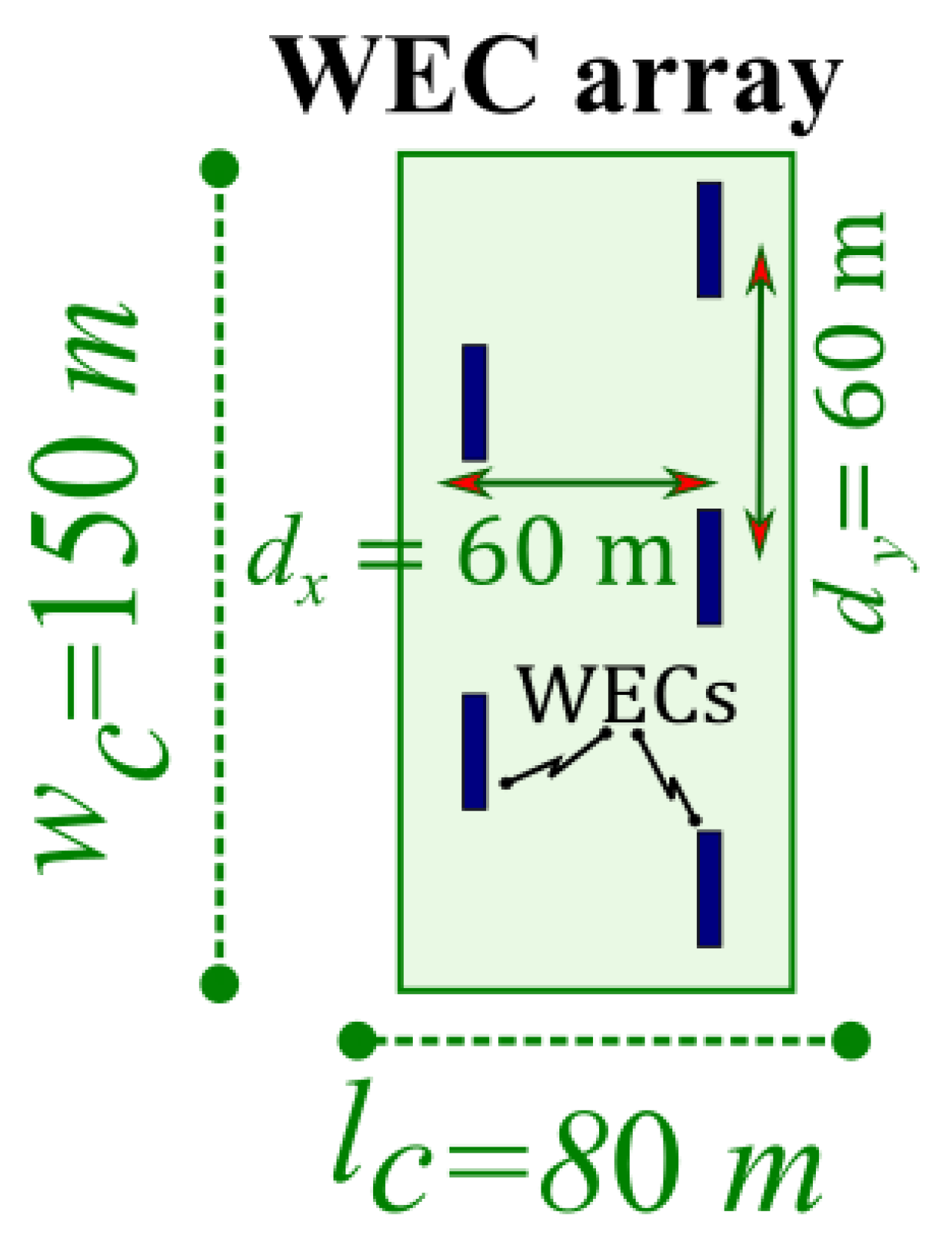
The full-scale WEC farm, shown in top view and in profile in Figure 4, consists of two rows of staggered arrays facing the prevailing wave direction; Δ x is 1 km. The bathymetry at the WEC farm location is modelled as a slope of 1/200 with the water depth ranging from 35 m at the offshore (WSW) side to 5 m at the near-shore (ENE) side. The location of the front WEC array row is at a water depth of 15 m while the back row is situated at a water depth of 15 m. Both depths are within the operating range of the proposed OSWEC technology, as mentioned in [6]. The 1 km WEC farm row separation distance allows the back row to avoid the worst ‘shadowing’ behind the front row, as the authors will witness in Section 5. The side to side separation distance Δ y between the centres of adjacent WEC arrays is 200 m, which is sufficient to minimize the lateral array effects of OSWECs. The WEC farm domain displayed in Figure 2 is orthogonal to the shoreline, or 240 ° from true North. This means that the WEC arrays are located 24 ° off the average incidence wave direction and 30 ° off the summer wave incidence. To simulate a realistic array of WECs, it was chosen a staggered configuration as has been previously utilized in both [1] and [11]. The configuration, along with the dimensions of the WEC arrays, is displayed in Figure 5. In addition to this study, such WEC array configurations were utilized in other investigations such as [19,47,49,50,51] with the motivation of maximizing the power output of an individual WEC array. It should be mentioned that the investigations of Tay and Venugopal [49] and Tomey-Bozo et al. [51] specifically deal with closely spaced OSWEC arrays in real sea states, mirroring the scope of the work in this study. As will be seen in the results displayed in the three tables in Section 5, the array orientation relative to the WEC farm axis is held constant while the angle of the incoming waves relative to the x-axis, β , is rotated for the wave directions modelled in Table 1. This choice is also realistic given that the OSWEC technology will be deployed parallel to the isobaths, which in our chosen scenario are also parallel to the shore.

2. Wave-to-Wire Model Methodology

In the next several section, the various pieces of the W2W model used in this investigation will be represented, including a description of the BEM WSI solver NEMOH in Section 2.2, and the details of the time-domain PTO module Section 2.7. A characterization of the wave propagation model MILDwave in Section 2.3, and finally the coupling which underlines the entire methodology of the study is introduced in Section 2.4. First, though, the modelling scenarios chosen for this real case study are given in Section 2.1.

2.1. Modelled Scenarios

In order to ascertain the influence of the wave climate on the WEC farm operation, the WEC farm is subjected to a variety of realistic wave conditions based on the wave climate data presented in Section 1.3. Before simulating these realistic multi-frequency sea states, the study investigates the WEC farm response for a regular wave of wave height H = 2 m and wave period T = 10 s, which is close to the mean annual values for the wave climate, to gain insight into the behaviour of the WEC farm. The shore-normal incidence angle β = 0 ° is simulated as a ‘base case’ scenario, against which the effects of the site average β = 20 ° are compared. The regular wave parameters are summarized in Table 2.
In simulating the wave climate based on the project site buoy data given in Section 1.3, one utilizes some of the trends inferred from the analysis in Section 1.3 to simplify the modelling. Namely, as the reader observed from the data in Table 1, the spring and autumn average wave climate is nearly identical. Therefore, modelling them separately would not result in an appreciable difference in the WEC farm power output. Note that the spring climate values closely track the annual averages. Therefore, in this investigation, it is decided to model only three distinct wave conditions, namely the summer, winter, and autumn wave regimes, with the respective H m 0 , T p , and β , which is equal to 275 − θ m . The wave parameters simulated to obtain the results in Section 4 and Section 5 are given in Table 3. The incoming wave incidence angle β is calculated as the difference between the WEC farm x-axis, which is 241 ° from North, and the three mean wave incidences θ m . Remark that directional spading is not modelled in this investigation.

2.2. NEMOH BEM Model Parameters

The smaller WEC array domain, corresponding to the area in Figure 4 and Figure 10 and detailed in Figure 5. NEMOH is an open source BEM code which has been extensively utilized in studies of WECs and WEC arrays, such as [1,10,51,52,53,54,55]. In brief, in a BEM solver, the interactions between the five WECs are solved using the Green’s function method given the meshed surfaces of the WECs everywhere in the domain. NEMOH solves the fluid flow via the Laplace equation that is simplification of the Navier–Stokes equations with the assumptions of Linear Potential Flow theory:
2 ϕ = 0
by means of Green’s functions, as detailed in [40]. The resulting velocity potential of the fluid, ϕ , allows us then to calculate the free surface elevations η for the WEC motions due to the diffracted and the radiated potentials via the free surface boundary condition:
η = 1 g ϕ t z = 0 ,
where g is the acceleration due to gravity and z = 0 is the undisturbed free surface. Here, the NEMOH domain over which the free surface is calculated is equal to 100 m in the x- and y-directions. The perturbed wave is calculated as the sum of radiated and diffracted η for wave frequency of the regular wave or the irregular wave component ω i utilizing the superposition principle. The water depths simulated in NEMOH are both set at 10 m. The OSWECs in deeper water are assumed to stand on a gravity base of height 5 m that would allow them to operate with the right submergence water depth of 10 m. For some potential designs of such a base see [6]. In this investigation, the BEM solver NEMOH is utilized for the small domains at a depth of 10 m to simulate the component WEC arrays in the WEC farm. While the solver would have limitations in highly nonlinear waves that are in the surf zone, in our investigation, the wave regime is safely outside of it for all simulated wave conditions. Further details on NEMOH are given in [40].

2.3. MILDwave Wave Propagation Model Parameters

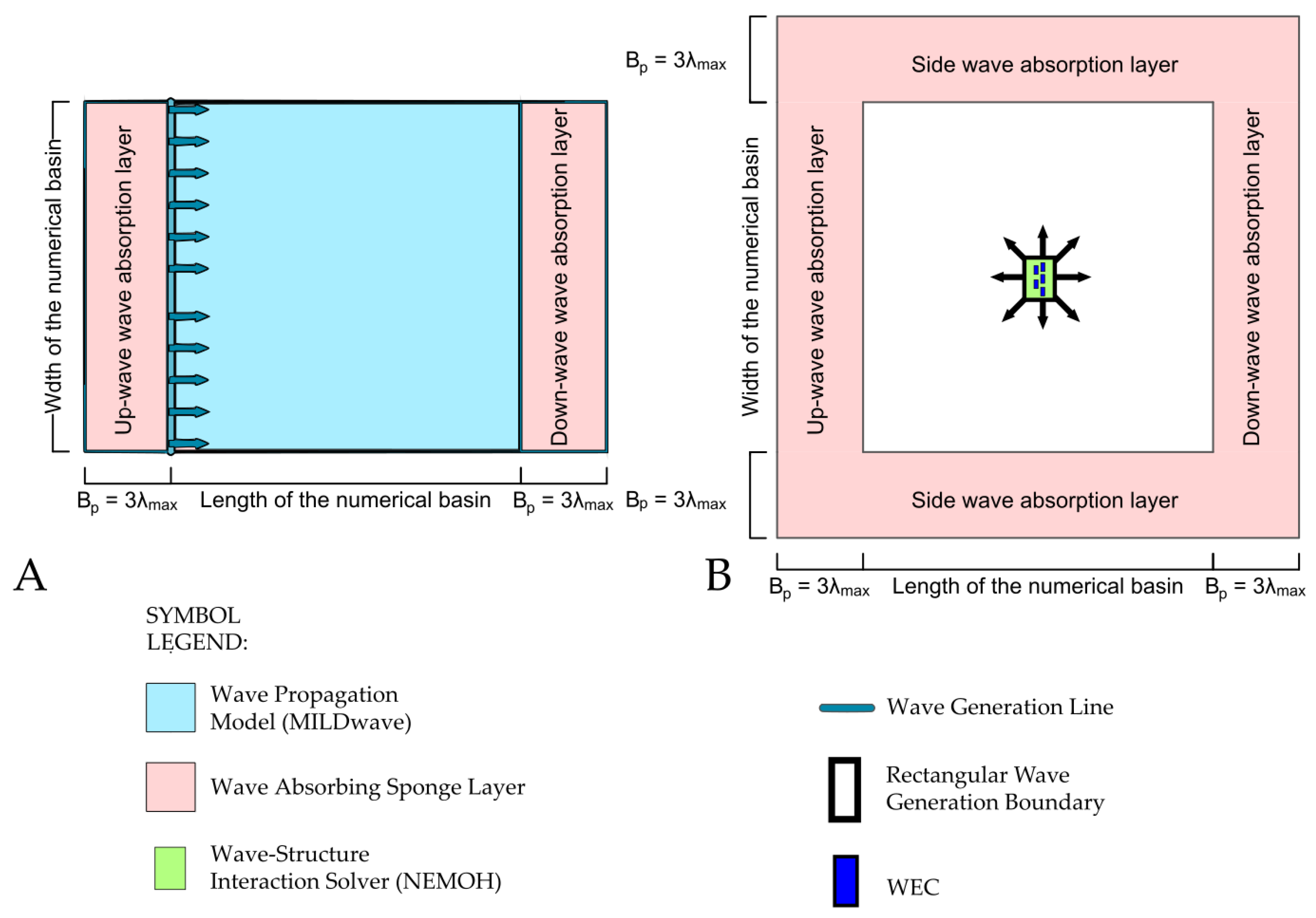
The W2W entire domain bounded by the yellow box in Figure 2 and Figure 3, and shown by the gradient in Figure 4 (top), is simulated in MILDwave, a phase-resolving wave propagation model developed at the Coastal Engineering Research Group of Ghent University, Belgium [9,56]. The model resolves the Berkhoff form of the Mild–Slope equations [57]. Although the modelled OSWECs were placed in an intermediate water depth, the largest part of the simulated domain is in deep water with only the shore side boundary in the shallow water regime based on the conditions modelled in Table 3. The flexibility of our coupling approach allows for the modelling in both shallow water and deep water conditions. MILDwave is run over an inclined bathymetry as shown in the bottom profile in Figure 4 with a slope of 1/200. The water depths range from 35 m offshore to 5 m near-shore. Sponge layers of 300 m width of the Elliptical type [45] are placed at the ends of the domain parallel to the y-axis to minimize wave reflection. The lateral boundaries parallel to the x-axis, are periodic, meaning that information leaving one end of the numerical domain enters the opposite end and thus the required model length in this direction is reduced. For details of the implementation of the periodic boundaries in MILDwave, see [58].

2.4. Coupling of NEMOH to MILDwave

In order to model the far-field effects in an efficient manner with a reasonable accuracy, the one-way coupling methodology presented in this study and detailed in [1,55] is employed between NEMOH and MILDwave. In brief, the perturbed wave field is calculated in the BEM solver NEMOH and is propagated into the water depth-integrated wave model MILDwave, on a rectangle large enough to enclose the near-field domain that contains the WECs. A schematic of the empty basin MILDwave domain and the coupled MILDwave domain for one WEC array is displayed in Figure 6. SL indicates the Sponge Layers, λ m a x is the maximum simulated wavelength. The coupling methodology allows for the flexibility of coupling multiple inner domains to the outer domain as shown in both the large domain Figure 4 and the small domain in Figure 10; this is utilized in preparing the results in Section 5, where the 10 NEMOH domains containing the 10-OSWEC arrays are coupled into MILDwave simultaneously.

2.5. Simulating Irregular Sea States

Because buoy spectral data are not available for the analysis site, one must chose a spectral representation to model the frequency distribution of an irregular sea state. Although various spectral parametrizations exist, since our proposed site is in the open ocean, it is not fetch-limited for the prevailing wave directions. One therefore can select a omni-directional Pierson–Moskowitz spectrum S P M ( H m 0 , T p , ω ) with N = 20 frequency components. The choice of spectrum was motivated by the domain being open to the full force of North Atlantic waves and the location of the OSWECs in intermediate water. The transformation of the deep water waves in the shallower parts of the simulation domain is executed in MILDwave. According to an analysis of existing work by Pastor and Liu [59], this is sufficient for WEC motion simulation. The wave amplitude ζ i of each irregular wave component is calculated as:
ζ i = 2 S P M ( H m 0 , T p , ω ) δ ω ,
where ω is the angular frequency component. S P M ( H m 0 , T p , ω ) is given by:
S P M ( H m 0 , T p , ω ) = 5 π 4 H m 0 2 T p 4 ω 5 e 20 π 4 T p 4 ω 4 .
The total wave elevation η for an irregular wave field is then the sum of ζ i , the unit amplitude wave. The total wave η i for each frequency component i is obtained using the procedure in Section 2.8. The coupling is performed at each ω i and then the total wave component ζ i is calculated as the sum of the constituent incident and perturbed waves. Finally, the irregular sea state is calculated by multiplying the resulting frequency components by the distribution given in Equation (4). In effect, this is equivalent to simulations of irregular seas within the framework of linear theory, such as in [49].

2.6. Modelled OSWECs

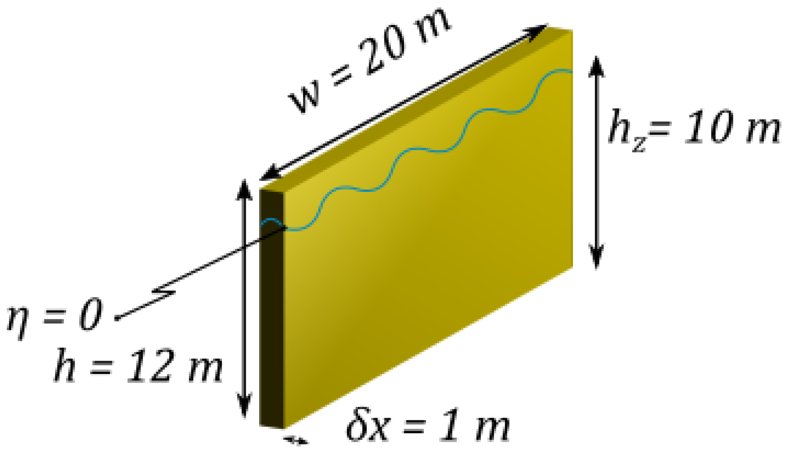
Bottom-fixed surface-piercing OSWECs are simulated with a width (w) of 20 m, a height ( h t ) of 12 m, a draft ( h z ) of 10 m, and a thickness ( δ x ) of 1.0 m (see Figure 7). The modelled WEC is activated by the surging force of the waves in the shallow water wave regime, with the wave force driving a pitching motion about the base attachment. The base is set at the sea bottom for the 10 m water depth, assuming a mounting structure that results in the same submergence profile for the 15 m water depth deployment. The OSWEC is similar to several pre-commercial WEC technologies, specifically the WaveRoller device [7]. The natural pitch period of the OSWEC is T r , 55 17 s.

2.7. Hydraulic PTO System and Derivation of the Optimal Coefficients for Irregular Waves

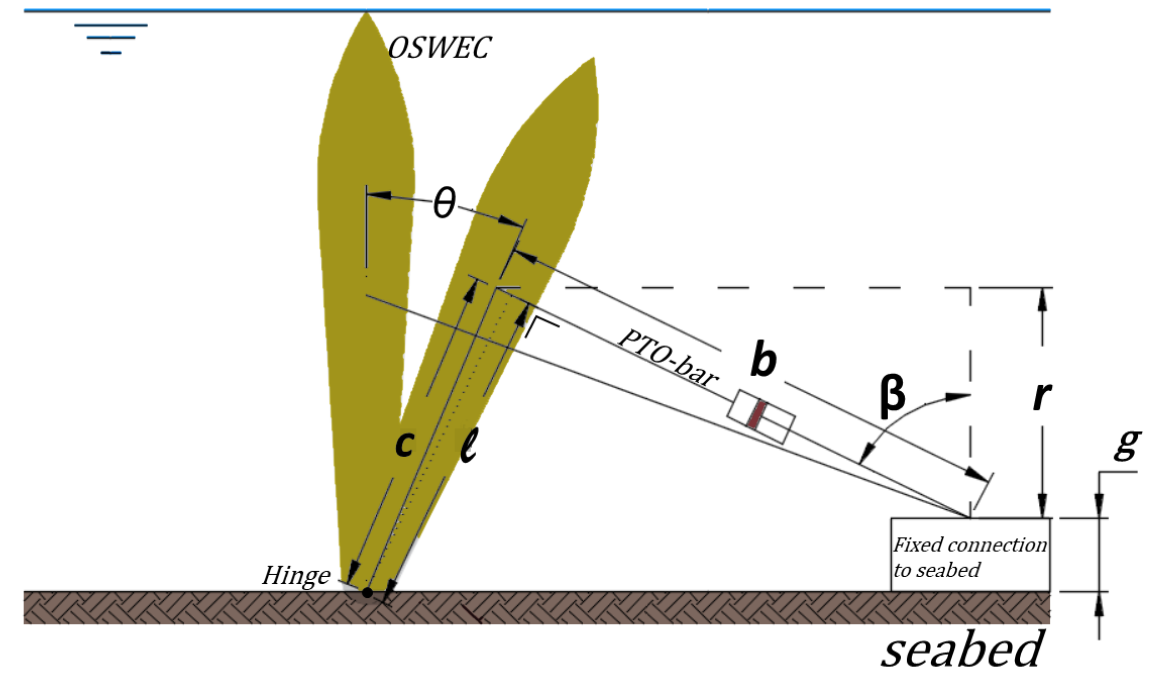
The PTO of each modelled WEC is a hydraulic system described in detail in [11]. The PTO is constructed in the Matlab Simulink® environment and then simulated in WEC-Sim, an open source purpose-built WEC dynamics simulator developed jointly by Sandia Laboratories and the National Renewable Energy Laboratory in the USA [12,34]. A schematic of the hydraulic system parameters is presented in Figure 8.
Here, b is the bar length, c the distance between the flap hinge and the PTO bar connection, and g the vertical offset of the PTO system. β is the angle beween the PTO bar and the vertical axis. For further detail please see [11]. As was done in Balitsky et al. [11], Cargo et al. [31], a hydraulic PTO system damping term B P T O , h is defined and checked for an optimum value. This B P T O , h is a coefficient that takes into account the parameters of the hydraulic PTO system that influence the performance of the WEC and has the same dimensions as the linear damping term B P T O , l : [(kg·m 2 )/s] for an OSWEC. For a single OSWEC in regular waves, B P T O , h is given in Equation (5). b i n i the length of the PTO-bar for θ = 0 ° :
B P T O , h = c · b i n i ( s c D m ) 2 B g .
Here D m is the motor displacement, B g is the generator damping, and s c is the piston area, where all three quantities vary with time. For an OSWEC, the optimum value for B P T O , h for a given frequency ω is searched for by varying the motor displacement D m , since it is the most convenient parameter to alter in practice. In the regular modelled wave case given in Table 2, B P T O , h = 121 10 6 kg·m 2 /s.
For an irregular wave simulation, the bulk hydraulic equivalent PTO coefficient is derived by taking the spectrally-weighted sum of the hydraulic motor displacements D m over the N wave frequency components:
D m , i r r = i = 1 N D m , i ( ω i ) · S P M ( ω i ) i = 1 N S P M ( ω i ) ,
where D m , i is the optimal motor displacement for angular wave frequency ω i and S P M ( H m 0 , T p , ω ) is the Pierson–Moskowitz spectral distribution used in this investigation and given by Equation (4) in Section 2.5. The irregular bulk hydraulic coefficient is then given by:
B P T O , h , i r r = c · b i n i ( s c D m , i r r ) 2 B g .
The choice was made to average out the motor displacements D m instead of the hydraulic damping coefficient B P T O , h , since D m is the parameter that is actually modified. Furthermore, the optimal B P T O , h for wave periods higher than 10 s decreases rapidly with increasing wave period. Thus, applying the weighted average in Equation (6) to B P T O , h instead of D m would have resulted in an unrepresentative value of B P T O , h , i r r . Each PTO coefficient in the OSWEC array is calculated by running WEC-Sim with the hydrodynamic coefficients given by NEMOH. The optimal B P T O coefficients for the three simulated wave states in Table 3 in Section 2.1 are given in Table 4. Note that the coefficients are the same across the five OSWECs in each array for each simulated set of wave conditions: because of the gradual slope of the curve of the OSWEC power output over the optimal hydraulic coefficient B P T O , h , i r r , the influence of the adjacent bodies on B P T O , h , i r r is minimal. It also must be mentioned that the nonlinear influence of the significant wave height H m 0 , on B P T O , h , i r r was found to be minimal; therefore, the coefficients depend only on the peak period T p .

2.8. Calculating the Total Wave Field in the WEC Farm

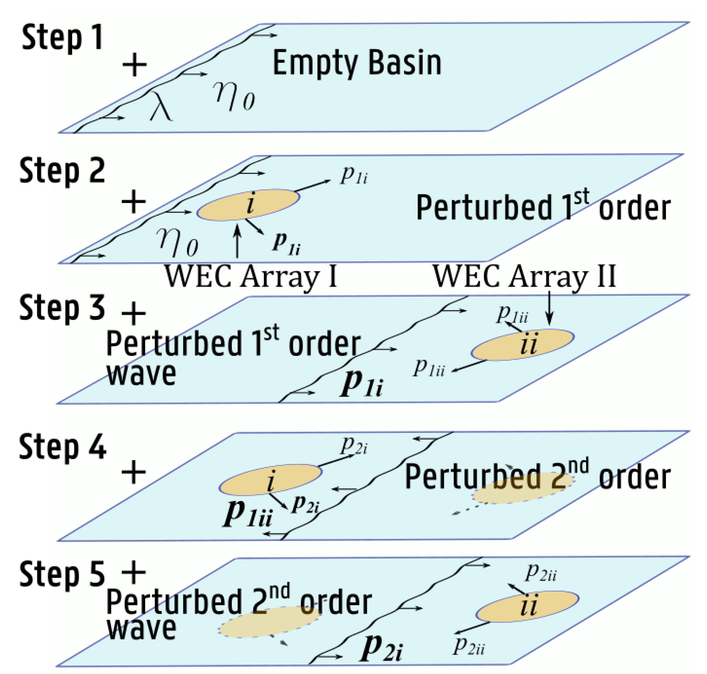
To assess the effects of the two WEC arrays within a WEC farm on each other, and in order to evaluate the power output of the farm, we calculate the total perturbed wave field in the MILDwave domain. As the present investigation assumes linear theory, one can use the superposition principle to sum up the total wave field by combining an iterative approach with the coupling methodology presented in Section 2.4. For clarity, the technique employed is illustrated in Figure 9 for the case of the small 2-WEC array domain of Figure 10. The initial step (Step 1) is to propagate the incident wave in the empty numerical basin to obtain the undisturbed wave elevation. In Step 2, the incident wave elevation is used as input into NEMOH whence the 1st order perturbed wave of WEC Array i, p 1 i , is evaluated. In Step 3, the average wave amplitude at the location of p 1 i is used as input into NEMOH to calculate the 1st order perturbed wave of WEC Array ii, p 1 i i . Since the input perturbed wave in each subsequent step after step is reduced by approximately an order of magnitude, for the irregular waves modelled in this study, the process can be stopped at Step 3 without an appreciable loss of precision in the calculation. In theory, this procedure can be continued to the 2nd order and higher. This procedure can be expanded to multiple WEC array farm such as the ones in Figure 4, where each sum is the totality of all order array effects. Further details on the summation method can be found in [1].

3. Calculating the Power Output of a WEC Farm Composed of Multiple WEC Arrays

To assess the influence of the WEC intra-array interaction effects on the performance of a WEC farm, the study computes the sum of the output power produced by the WEC arrays, after having obtained the modified wave field in the WEC farm using the approach outlined in Section 2.8. The procedure is outlined as follows:
  • the wave field inside each WEC array is computed in NEMOH using Equation (2),
  • the power of each WEC in the array is calculated in WEC-Sim using the amplitudes output by NEMOH and summed for the M WECs,
  • the average perturbed 1st order wave field of the W2W model is computed at the WEC array perimeter,
  • the power of the WEC array is multiplied by the wave field computed in the previous step,
  • the power of the WEC farm is then the sum of the power of all constituent WEC arrays.
For each WEC array, for one angular wave frequency component ω i , the WEC array power output is calculated in item 2 by simulating the OSWEC motions in WEC-Sim using Equation (8). The input wave amplitude of the total η at the locations of the WECs is the input determined in item 1 above for each body j over the wave period T i :
P j , i , a r r a y ( ω i , β i ) = 1 T i j = 1 M 0 T i T j , P T O ( t ) · θ j ˙ ( t ) d t .
Here, M is the number of bodies in the WEC array, T j , P T O is a column vector of torques of each OSWEC, and θ ˙ j is a column vector of the angular displacements of each OSWEC. The simulations are performed in WEC-Sim with the amplitude given by the total η at the WEC location determined by the procedure detailed in Section 2.8. For simulating irregular wave scenarios, the power output is given by the sum of the power at each ω i , calculated by Equation (8) weighted by the omnidirectional Pierson–Moskowitz spectrum S P M ( f ) given in Equation (4)
P a r r a y , i r r = 2 i = 1 N Δ ω S P M ( H m 0 , T p , ω ) P i , h ( ω , β ) .
In Equation (9), Δ ω is the frequency bandwidth of the spectrum discretization and the number of frequency components, N = 20. To obtain the total power output of the WEC farm in item 3 in Section 3, the study runs the iterative procedure of Section 2.8 to obtain the total 1st order η and subsequently multiply the value obtained in Equation (9) by the value of the η at the perimeter of the array. Because the WEC array inner domain region includes the WEC bodies and the immediate surrounding area which is subject to the limitations of the linear BEM calculation, one choses the mean value of η on the perimeter of the WEC array regions to provide a representative value of the total wave field perturbed by the far-field array effects of the surrounding WEC arrays. Finally, P f a r m is given as the sum of P a r r a y given by Equation (8) for regular waves and Equation (9) for irregular waves:
P f a r m = k = 1 N P a r r a y ,
where N is the number of WEC arrays in the farm. To measure the relative power output which reflects the WEC array effects in the modelled WEC farm, this study introduces the WEC farm q-value. The definition presented here differs slightly from the q-value presented in literature such as [46,47,50,60], where it measures the intra-array effects. The study measures the inter-array effects in the WEC farm by defining q as:
q = P f a r m P i s o l ,
where P f a r m is the total WEC farm power defined by Equation (10), including all interactions. P i s o l is calculated as if the N WEC arrays were isolated, but the intra-array effects are included in this power calculation.

4. Results for a 2-Array 10 OSWEC Farm

As a first step to modelling the full 50 WEC farm in a 6.0 km by 2.0 km domain, a reduced size 10 OSWEC farm consisting of two WEC Arrays is modelled in a 1.0 km by 2.0 km domain and the same wave climate as for the 50 WEC farm, were used, to demonstrate the quantitative aspects of a multi-array OSWEC farm in a real sea state. The OSWEC array locations are at the same depths as the full scale farm modelled in Section 5 and are located at 15 m water depth (front array) and 10 m (back array), maintaining the sloping profile of the full scale WEC farm domain. A schematic of the 10 OSWEC farm is shown in Figure 10. The purpose of this section is to elucidate the main features of the WEC farm wave field | η | and to highlight the differences between the regular and the irregular wave case. | η | is defined as the absolute value of the complex total wave amplitude and is synonymous with wave field for the purposes of this study. As was commented on in Section 1, the majority of WEC array studies to date have been performed in regular wave simulations. Therefore, it is important to have a base case to compare with the small basin irregular wave results presented in Section 4.3.

4.1. The 10-OSWEC Farm Wave Field for a Regular Wave at β = 0 ° Incidence

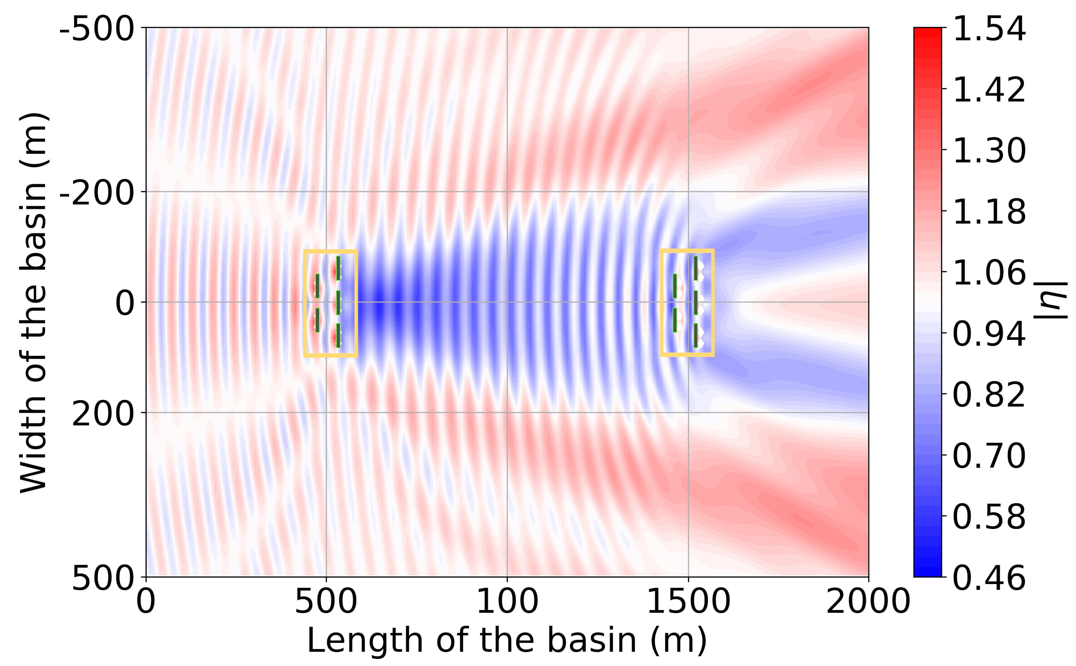
To assess the impact of the WEC arrays on each other and on the surrounding wave field, the study first shows a contour plot of the absolute value of the complex wave amplitude | η | for the regular wave of H = 2 m and T = 10 s. These conditions are representative of the mean site wave climate with a β = 0 ° , given in Table 2 and in Figure 11. Note that the area inside of the yellow boxes is the inner model coupling domain as explained in Section 2.4, and is shown for completeness only. The solid rectangles represent the locations of the OSWECs. This investigation does not consider the inner domain values of η in the analysis of the coupled wave field. This rule will apply to the contour plots presented in this and the subsequent, Section 5.
Looking at Figure 11, the first that is apparent is the very strong interference pattern between the two WEC arrays in the WEC farm. There are areas of enhancement of η which the authors term ‘hot spots’ and areas of reduction in the mean η which are commonly referred to as the ‘wake zone’ or the zone of ‘shadowing’. The largest wake zone is observed behind the front WEC array, which is the one that is located on the left side of the basin in water depth of 15 m. There is a large area of reduction of up to 40% of the incident wave field in a region several hundred meters behind the array location and extending to about twice the width of the WEC array in the y-direction. In contrast, behind the second WEC array, one does not see such a pronounced wake zone; instead, one observes a hot spot aligned with the x-axis. The primary reason for this discrepancy is that the back WEC array is located in a shallow region of only 10 m water depth. There is significant wave reflection behind it with the shallow bathymetry zone which one can infer from the profile in Figure 10. In addition, as a consequence of the interaction of the refraction of the OSWEC arrays and the sloping shallow bathymetry, large areas of positive anomalies are found on the shoreward boundary at a vertical distance of 500 km away from the WEC array centres. Also note the significant interference effects between the perturbed waves of the WEC array and the incident wave that is manifested in the strong interference pattern between and seaward of the two OSWEC arrays.

4.2. The 10-OSWEC Farm Wave Field for a Regular Wave at β = 24 ° Incidence

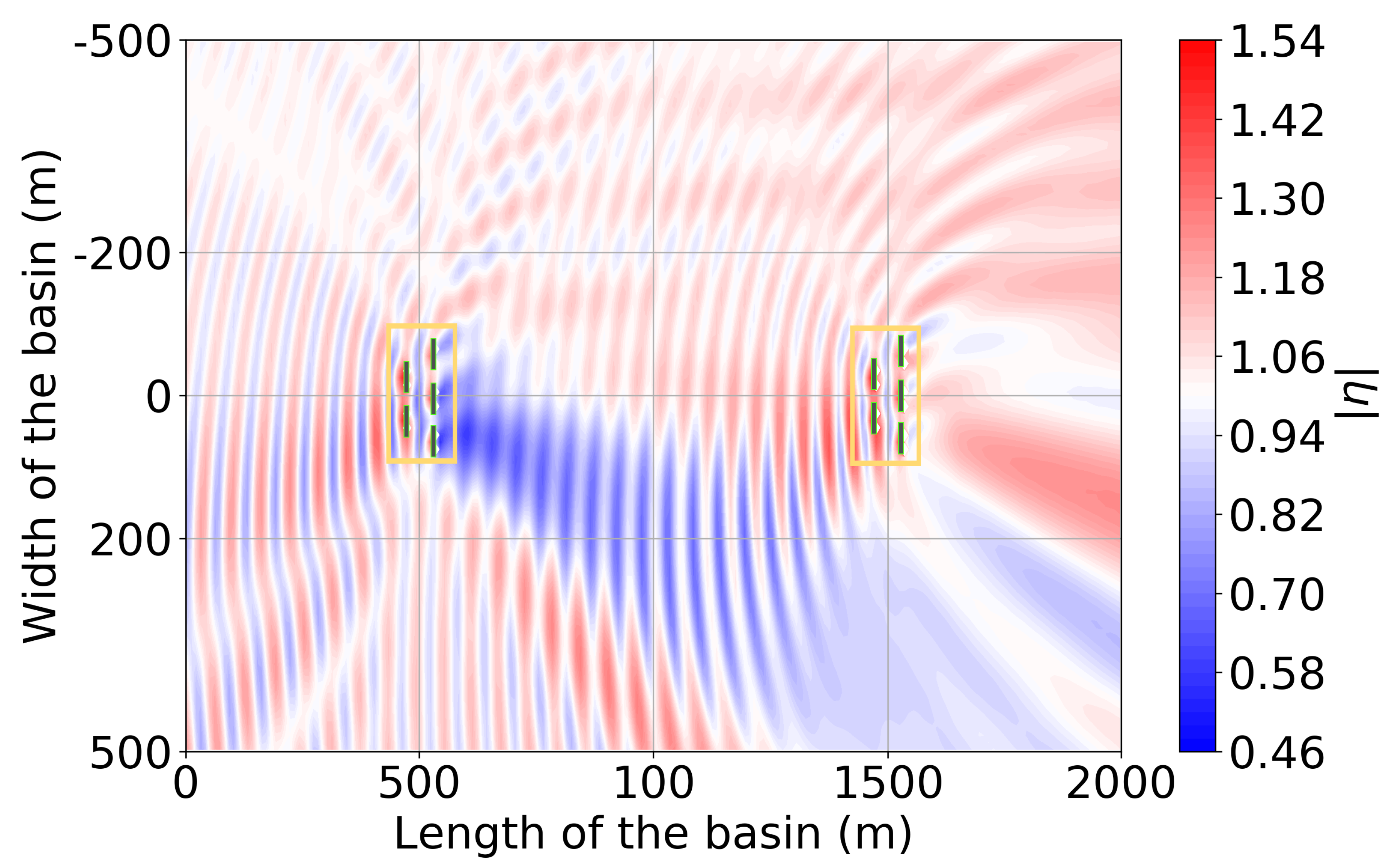
The next scenario modelled is the 10-OSWEC farm displayed in Figure 10 for H = 2 m and T = 10 s but with an incidence angle β = −24 ° . This is the regular wave equivalent to the mean site conditions observed at the WEC array project site as detailed in Section 2.1. Again, as pointed out at the beginning of Section 4, the study models this scenario to highlight the difference in the behaviour of a WEC farm aligned with the incoming incident wave versus one that is off-angle, such as the case for the average wave climate of the investigated WEC farm project site.
As expected, the observed total | η | in Figure 12 is quite different from the one shown in Figure 11. Note the asymmetry in the interference patterns and the areas of positive versus negative anomalies. One sees that the majority of the area below the y-axis is a wake zone, while above the y-axis there is a large area of hotspots with an increase in | η | close to 20% as one moves toward the shallower region on the right side of the domain. Naturally, this is due to the wave incidence angle of β = 24 ° , in which one would expect most of the reduction in | η | from the WEC arrays to occur on the left bottom side, opposite the wave incidence. However, the pattern is complicated by the fact that there is significant reflection from the OSWECs which also creates the strong ‘rays’ of interference at an angle 90 ° counter-clockwise from the incidence. β in the modelled case is approximately equal to β = −110 ° . Note that the maximum enhancement in η is greater than β = 0 ° case in Section 4.1 but that the area of such enhancement is very limited, negating the possibility of using this fact for an optimal positioning of WECs. As the authors will observe in Section 4.3 in the complementary results for the irregular wave case, this constructive interference is nearly absent. This fact has significant consequence for the power output of WEC arrays in a WEC farm with angled incidence waves. The power output of the WEC array will be reflected at incidence angles different from those parallel to the wave incidence as the authors will see for the full WEC farm results with off-axis incidence angles β in Section 5.4.

4.3. The 10-OSWEC Farm Wave Field for an Irregular Wave at β = 0 ° Incidence

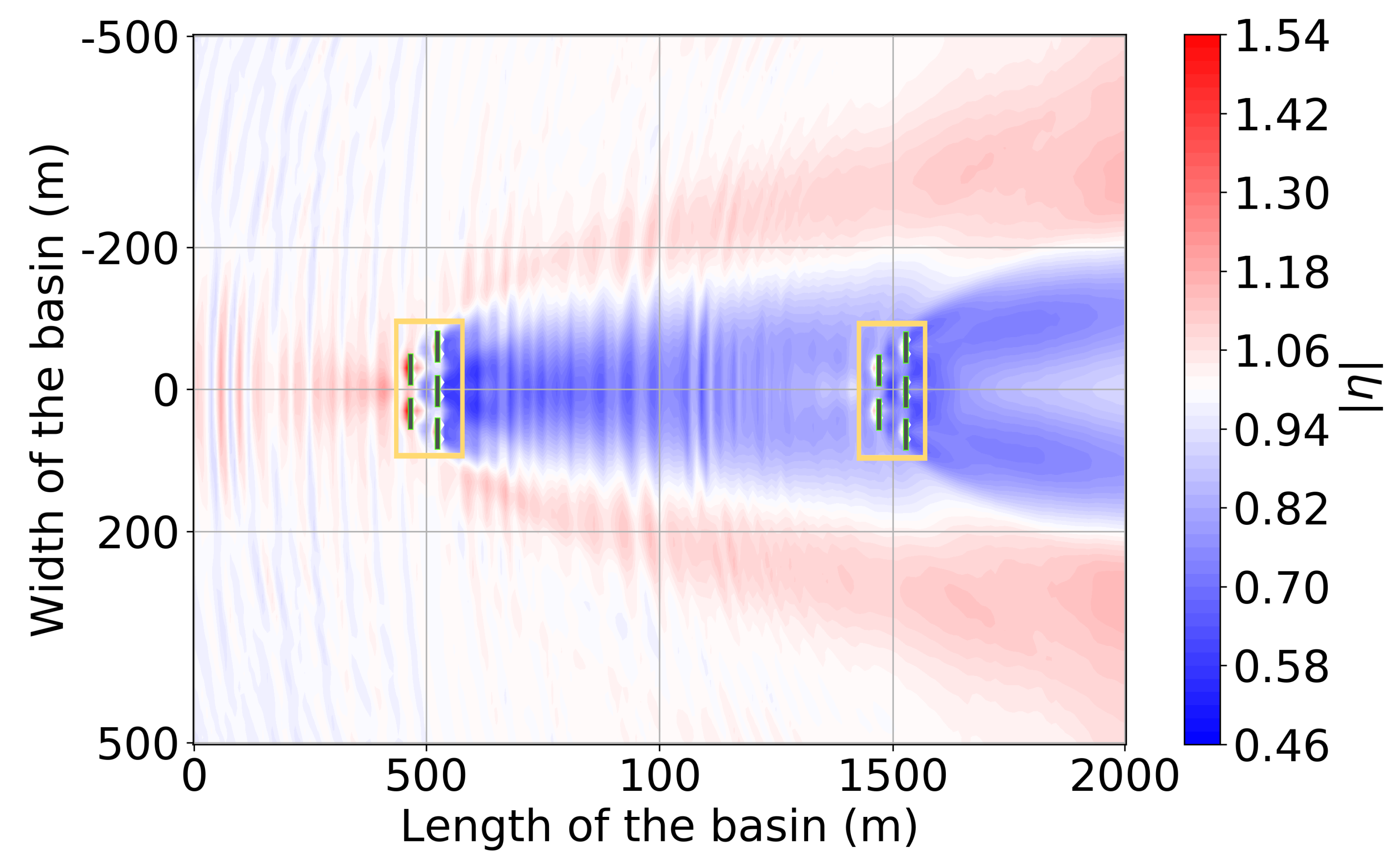
In this section, the investigation presents the irregular wave results for the same modelling scenario introduced in the previous Section 4.1 and Section 4.2, where the regular wave of H = 2 m T = 10 is substituted by an irregular wave with a H m 0 = 2 m and T p = 10 s, where the frequency distribution given by the Pierson–Moskowitz parametrization given in Equation (4).
One can observe the significant differences between the results presented herein in Figure 13 and the regular wave results of Section 4.1. Firstly, the strong pattern of constructive and destructive interference is greatly reduced, owing to the smoothing effect of the multi-frequency sea state. Furthermore, there is a significant reduction in the magnitude of the ‘hot spots’, particularly one in the lee of the two WEC arrays at the x-axis. The wake zones, meanwhile, were not reduced in magnitude or extent, but, in fact, have a more extensive area of reduced | η | . This phenomenon is part of the reason that the authors see a near-field influence of constructive influence on the power output for the OSWEC farm modelled in the full scale farm results in Section 5.4.

4.4. The 10-OSWEC Farm η for an Irregular Wave at β = 24 ° Incidence

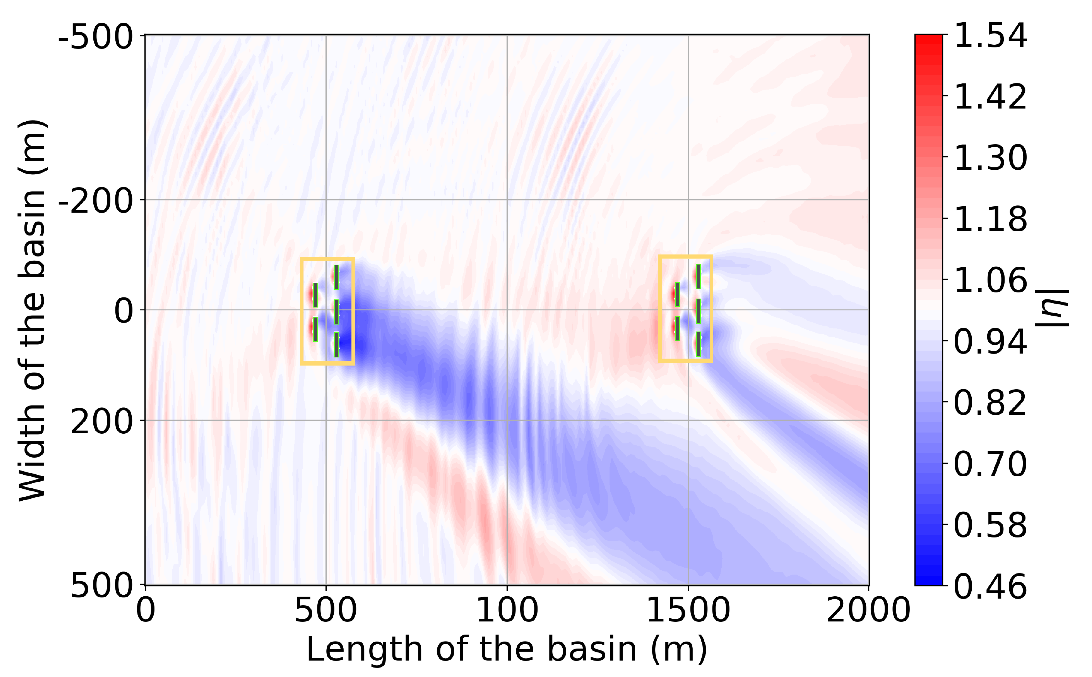
Analogous with the comparison made in the previous Section 4.3 between the regular and irregular results for β = 0 ° , the difference between the β = 24 ° results for regular and irregular waves are significant. In Figure 14, one can observe that the majority of the domain is either in a neutral zone, that is no change in the η due to array effects, or indeed in the wake zone. Note how the strong wave reflection that is so prominent to the left bottom side of the OSWEC arrays is absent in the irregular weave results. This outcome is due to the fact that the OSWEC is much more reflective to a single component T = 10 s wave than a multi-frequency T p = 10 s wave. As in the regular wave case, one sees a skewing of the wake zone, where the back WEC array is not in the wake zone of the front one anymore as in Figure 11. This is a potential benefit for an aligned WEC farm configuration such as the one presented here. The results will be mirrored in the q-values exhibited in Tables 8–10.

5. Results for a 10 Array 50 OSWEC Farm

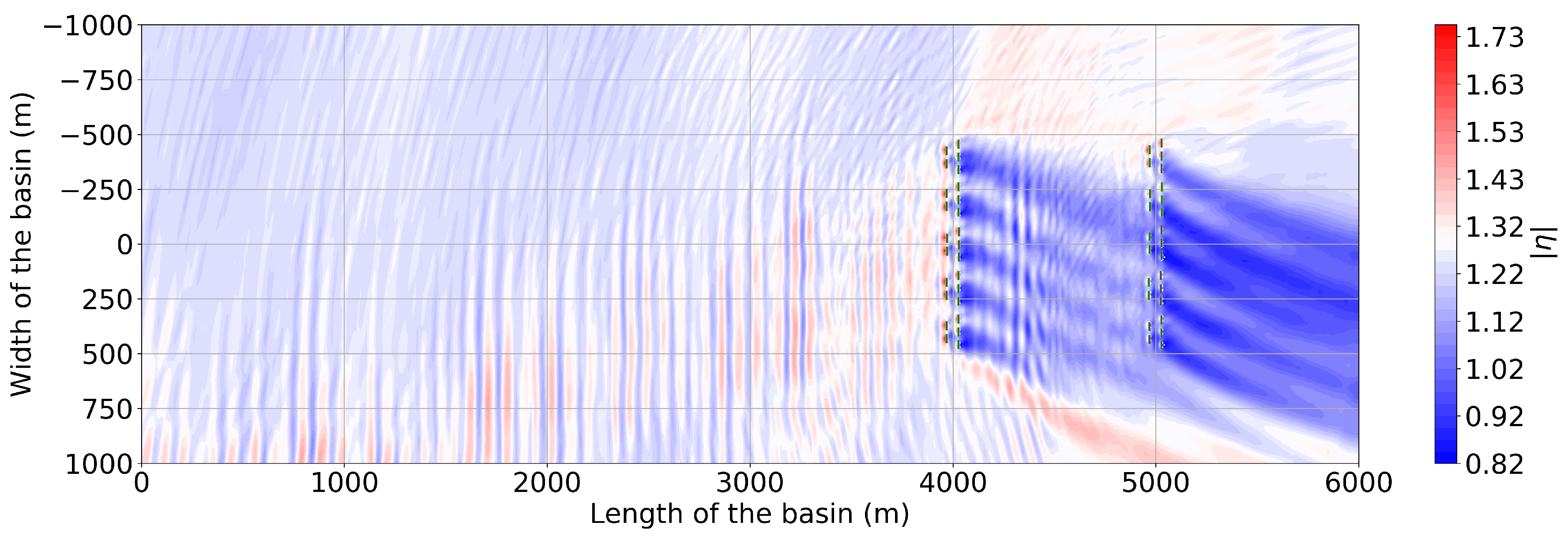
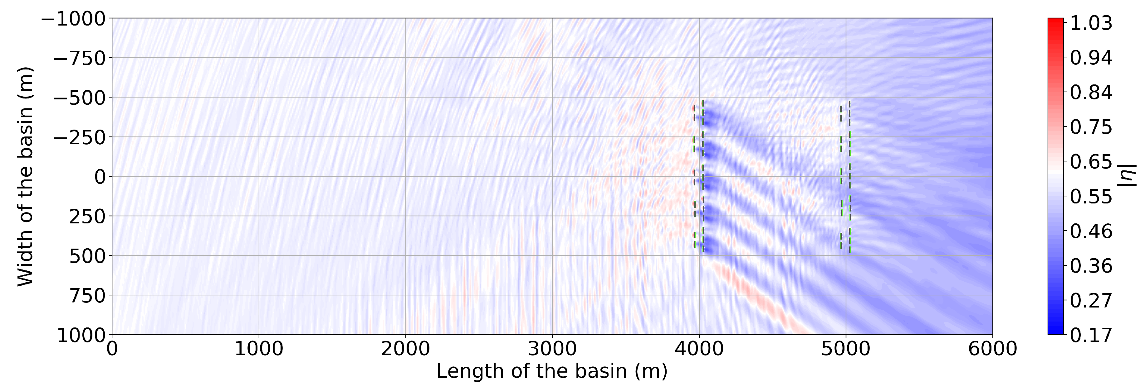
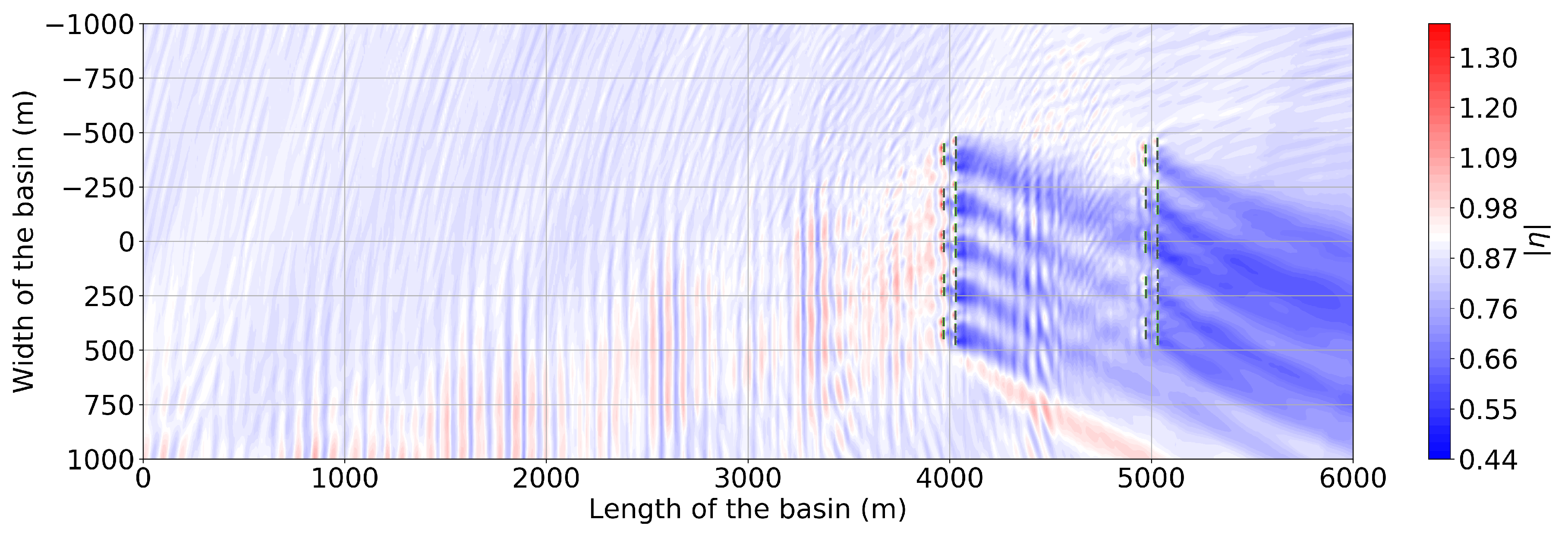
In this section, the investigation demonstrates the key results of the present study given by the W2W model described in Section 2: the wave field and the power output of the 50 WEC farm, which is illustrated in Figure 4. The inner domain of the WEC arrays is shown by orange rectangles in all the contour plots of η and the individual WECs are indicated by small solid rectangles. In the next three sections, Section 5.1, Section 5.2 and Section 5.3, the mean | η | for the three seasonal wave climates of Section 2.1 is displayed in Figure 15, Figure 16 and Figure 17. Then, the power output of the WEC farm is presented in Table 5, Table 6 and Table 7 in Section 5.4. Note that the absolute value of the wave amplitudes η demonstrated herein are not normalized by the incident waves to show the absolute difference in the three wave climates. Warm coloured areas indicate | η | greater than the mean wave elevation for a given H m 0 while cold colours indicate wave elevations below the mean.

5.1. The 50-OSWEC Farm Wave Field for the Site Winter Climate

The coupled values of the total | η | for the mean site winter wave climate of H m 0 = 2.55, T p = 11.71 s, and β = −20 ° are shown for the WEC farm domain in Figure 15. The first effect one notices from the contour plot, Figure 15, is the large wake zone behind the 1st and the 2nd row of the WEC farm. In contrast with the regular wave case for the small WEC farm presented in Figure 11 and Figure 12, but mirroring the small basin irregular wave results in Figure 13 and Figure 14, there are almost no areas of hot spots. Instead, one finds only a narrow band of positive η anomalies parallel to the wave incidence of β = −20 ° from the front WEC array row. The wake zone, however, is extensive: the average wave amplitude at nearly all of the shore side (left-hand side) domain boundary is reduced by roughly 0.4 m, which is nearly 25% of the incoming H m 0 of 2.55 m. In addition, note that, for this particular wave angle, the alignment of the WEC arrays is such that the wake zones extending from the 1st WEC array row are shadowing the lower placed second row array. The reader shall see this effect reflected in the values of the power output displayed in Table 5, Table 6 and Table 7. Notice that the shoaling effect, such as that observed for the regular wave case in the small domain in Figure 11 and Figure 12, is dominated by the significant shadowing of the WEC farm. In this case, a slight enhancement of | η | due to this effect is only observed in the upper right side of the domain, where the influence of the WEC farm is minimized.

5.2. The 50-OSWEC Farm Wave Field for the Site Summer Climate

When one studies the total coupled absolute wave amplitude | η | for the summer climate in Figure 16, it is striking to observe that nearly the entire domain is an area of negative anomalies in η . Because the summer mean peak wave period T p = 8.71 s, the shoaling effects of the decreasing water depth are minimal. Therefore, the overriding effect on the shore side boundary is a decrease in η of 0.10 m to 0.15 m off the mean incident η of 0.6 m, which is approximately equal to a 15% to 20% reduction in the mean η . Interestingly, for the modelled wave incidence of β = −30 ° , in contrast with the scenario presented in Figure 15, in Section 5.1, the back array is aligned with the positive regions of interference behind the front row. This indicates that, for the particular wave incidence, the placing of the arrays in the WEC farm is advantageous from the point of view of WEC farm power output. Indeed, observe that the back row q-value for the summer climate case in Table 9 is 0.10 m higher than for the other two wave climates. Likewise, for the smaller wavelength modelled in this scenario, the interference patterns are nearly averaged out, in contrast to the more apparent one in Figure 15 or in Figure 17.

5.3. The 50-OSWEC Farm Wave Field for the Autumn Wave Climate

Finally, the contour plot of the mean η in Figure 17 for the autumn mean wave climate, with H m 0 = 1.71 m, T p = 10.54 s, and a β = −22 ° , presents a picture very similar to the results for the winter that was exhibited in Figure 15 in Section 5.1. However, a close observation will highlight some discrepancies. Notably, the near-shore positive anomalies in η due to the shoaling effect are significant for the winter wave climate while, for the autumn wave climate in Figure 17, there is no appreciable positive anomaly in η in the same region. Observe also that the slight change in the incidence β of 2 ° from the winter case modifies the shoaling effect of the front WEC farm row on the back, but that the overall effect is still negative as observed in similar reduced q-values of the back row in Table 8 and Table 10. Moreover, observe the reflected zone of mostly positive interference that is reflected of the front WEC array row at a β approximately equal to −120 ° . While this effect is not as large in magnitude as the one which is observed for the winter climate case in Figure 15, it is still appreciable in contrast to its absence for the summer climate of Figure 16. Finally, note the near absence of the shoaling effect, indicating that, for this wave incidence of T p = 10.54 s, it is not significant enough to influence the ‘wake zone’ at the shore boundary.

5.4. The Power Output of a 10 Array 50 OSWEC Farm for the Seasonal Wave Climate

The reader has seen how the wave field is modified in the presence of the 10 OSWEC arrays in Figure 15 and Figure 17 and Section 5.2 for the three modelled scenarios of Table 3 in Section 5. Now, one turns attention to how the changes in the wave field are reflected in the power absorption of a 50 OSWEC farm in a realistic operating environment. The investigation calculates the power for each array consisting of five OSWECs for the three irregular sea states displayed in Table 5, Table 6 and Table 7 using Equation (9). The results are displayed by back and front WEC row to emphasize the shadowing effects within a WEC farm. The study first introduces the absolute values of the WEC farm output in kilowatts in Section 5.4.1 and then displays the same values in relative terms using the q-value in Section 5.4.2 for emphasis of the WEC array effects.

5.4.1. Absolute Power Output of the 50-WEC Farm

The first thing one observes in all three Tables, Table 5, Table 6 and Table 7 is the asymmetry in power output due to the off-axis angle of incidence β for the modelled wave climates. Notice that, in all three cases, the power output from the front row is greater than that of the back WEC array row, yet the constant of proportionality in the difference is not the same across the three simulated cases. As was referred to in Section 5, this disparity is due to the interplay of the WEC array row side-to-side separation and the wave incidence angle β for the three cases. Also observe that, for the irregular wave cases studied, the location of the back array in shallower water does not compensate for the reduction due to the presence of the front WEC array row. That is, the shoaling effect which increases the wave amplitude driving the power output cannot overcome the significant reduction in η imparted by the front row array of OSWECs.
In looking at the difference between adjacent rows of WEC arrays, that is along the y-axis, one can see an attenuation in the power output as one moves from the outer arrays to the inner most ones for the winter and autumn cases in Table 5 and Table 7. However, this is a uniform decrease as one moves down the y-axis for the summer power output in Table 6. This disparity is chiefly due to the 10 ° higher wave incidence β for the summer climate. In studying the values of the individual WEC array power output, the two arrays down-angle from the wave incidence, that is, WEC arrays ix and x are the most shadowed, while, for certain wave scenarios, the respective arrays on the positive y-axis side of the farm, i and ii, are in fact producing power nearly equal or slightly above the mean. In terms of the overall power output, one sees a slight reduction between the winter and the autumn values, but a significant reduction in the summer values compared to the winter power. This is expected of the highly variable North Atlantic wave climate, and it indicates the need to study seasonality in the WEC farm power output as opposed to using a mean annual value.

5.4.2. Relative Power Output of the 50-WEC Farm

In addition to looking at the absolute power values in Table 5, Table 6 and Table 7, it is also useful to look at the relative differences in the power output, normalized with P i s o l a t e d , given by the q-value of Equation (11). The values displayed in Table 8, Table 9 and Table 10 are for the three wave climates investigated. Notice that the highest q-value is for the summer wave climates, which is when the total power output is in fact the lowest, as seen in Section 5.4.1. Note that nearly all q-values are below unity, indicating that the array effects on the OSWEC farm is generally negative. This is a consequence of both the strong reflection and shadowiness of the individual OSWECS, and the fact that the layout of the WEC arrays is not optimized. Again, one observes that the back WEC array row q-value is significantly lower than the front WEC array row q-value. This indicates that the back arrays suffer from the proximity of the front WEC array rows, that is, the wave field has not had a chance to recover over the 1 km separation distance. Notice that, for the summer climate, the front WEC array row is an area of mostly constructive effects. This is a good result from the standpoint of the WEC farm economics, as this would tend to slightly improve the performance in what is usually the lower output period of the year.

6. Discussion

From the contour plots of | η | given in Figure 15, Figure 16 and Figure 17 and power output results in Table 5, Table 6 and Table 7 in Section 5.4, one can see the importance of looking at both the near-field and the far-field effects in analysing the WEC farm. The former are key in determining the WEC farm power output, as the power of each WEC array is determined by its constituent devices’ motions that are in turn proportional to the perturbed wave field. The reader has seen that a slight change in the incoming incidence angle from β = 0 ° to β = 20 ° has an appreciable impact on the WEC farm performance such as the difference in the q-value between Table 8, Table 9 and Table 10. In effect, this shift in the wave angle renders the present configuration more staggered which is of net benefit to the WEC farm performance because of decreased shadowing in the back row.
Looking at the shore side, the far-field effects that are necessary to assess the impact on the coastal zone down-wave of the modelled WEC farm, one sees a pronounced difference between the winter and summer climates, but a much lesser discrepancy between the winter and autumn. This difference is due to both the wave height and wave period of the winter and autumn waves, but also the difference of 10 ° in the wave incidence angle β plays a role by modulating the effect of the front row of OSWECs on the back row. Because of shoaling effects that impact the higher wave period components of the H m 0 = 2.5 m, T p = 11.71 s wave, the area and the magnitude of the ‘wake zone’ of the 50 WEC farm is slightly reduced compared with the smaller wave period autumn wave. The shoaling effect is completely absent with the summer waves of H m 0 = 1.20 m and T p = 8.71 s, where the reduction in the η is nearly uniform at 15–20% on the shoreward boundary of the modelled domain. There is no appreciable increase in | η | as one moves into the shallower zone of the domain. This is a key result of our work that indicates that the near-shore impact area of a OSWEC farm is more dependent on the incidence wave angles than on the changing bathymetry. One would not intuit this fact from a study that does not take changing incidence angle β and the bathymetry into account. In contrast, the total wave field up-wave of the WEC farm differs between the three incidence angles, yet the small magnitude of these effects and the lesser strategic importance of offshore zones for most coastal areas means that quantifying them is of less importance to the WEC farm developer.
Most economic studies conclude that a large number of WECs must be aggregated in a small area in order for them to be economical. Many studies have been performed to date exploring the optimal configuration of WEC farms or arrays, for example [60,61,62], yet most of them have focused on a WEC array of a few buoys. The few that did, such as [63], did not investigate WEC farms over variable bathymetry. Furthermore, an analysis with a real wave climate such as performed in this investigation, has hitherto been performed only for the calculation of economic variables, such as by de Andrés et al. [61], but not for the near-field effects. Conversely, investigations such as Rijnsdorp et al. [64], calculate the near-field effects in a WEC array but do not have the coupling with a motion solver which can accurately calculate the power output of the WEC array using a realistic PTO.
Although an optimization scheme can be set up that takes a large number of individual WECs as inputs, such as the parametric optimization study [19], for large numbers of WECs such a study is still numerically expensive, especially for WECs whose hydrodynamic parameters cannot be simplified analytically. Moreover, even if such an optimization is performed, these results are often times hard to intuit because of the many variable inputs involved in the optimization of a WEC farm that are hard to connect to the outcome. Accordingly, the simplifying approach the investigation employ, not only reduces the time of calculation by a priori grouping WECs in clusters that the authors term arrays, but also provide an intuitive link between WEC farm layout and the power output. The link between the two is via the perturbed wave field. Because the most important constructive and destructive effects in the WEC farm are of the 1st order, the approach presented in this study can be utilized to make a rapid visual assessment of various WEC farm configurations.

7. Conclusions

In this study, the perturbed wave fields have been calculated and analysed the power output of a conceptual 50 OSWEC farm using the W2W model with a coupling between a BEM solver, a PTO simulator, and a wave propagation model in a real wave climate and an actual water depth profile off the west coast of Bretagne, France. The presented W2W model combines the advantages of a PTO dynamic solver and a WSI solver to accurately model individual WEC hydrodynamics and nonlinear PTO hydrodynamics. At the same time, it allows for the modelling of large domains in the study of WEC array effects via a fast depth-integrated wave propagation solver. The combined model therefore allows the accurate modelling over a larger spatial and temporal extent than each of the modules individually. Concurrently, given the underlying assumptions of linearity underlying the individual modules and the coupling methodology, the present model is not appropriate for real-time control and/or survivability mode, where large, nonlinear WEC motions dominate.
The introduced W2W model was utilized in deriving the results in Section 4 in a small domain with a shallow sloping sea bottom, ranging from a water depth of 17.5 m to 5 m. Here, the reader observed how the wave field of a 10 OSWEC farm is influenced by the change in the wave incidence angle β . In the small basin results, the reader has seen the difference in the regular and irregular wave effects on the WEC farm near-field, especially regarding shoaling and reflection effects. The reader has also observed the consequential impact of the incident wave angle β . It has also been demonstrated that significant wake effects can extend out to more than 1 km or over 12 wavelengths behind the arrays, even for a small WEC farm of two arrays of 10 OSWECs. Furthermore, for the medium size WEC farm of 50 OSWECs, modelled in a large domain extending to shallower water of 5 m water depth, the predominance of WEC farm shadowing effects over the shoaling effects was determined. There is a consistent reduction in the shore side η from 10% of the incident wave height to well over 40% for a large section. The influence of the wave incidence angle β in the near field is significant, notably in its impact on the power output of the WEC array as seen in Section 5.4. It is diminished as one moves into the far-field regions away from the locations of the WEC arrays. Shallow water depth affects higher wave period waves more strongly. They are the longest-travelled components of the perturbed wave field; consequently, the near-shore zone impact of the WEC farm is similar for both incidence angles. Thus, the area of maximum reduction of η in the lee of the arrays is more aligned than it would have been in the absence of shoaling affects. However, because of the close proximity of the near-shore WEC farm to the coast, the skewed site wave incidence angle moves the area of the maximum of the shadowing effect off the WEC farm axis. This means that areas away from the zone of the WEC farm could potentially be affected by this reduction in the incoming wave amplitude, a fact that needs to be taken into account by the WEC farm developers.
Even though the effect of the simulated WEC farm configuration on the power output is mostly negative, as witnessed in the q-value in Table 8, Table 9 and Table 10, the relative placement of the WEC arrays is still of utmost importance as the difference in power output of the most shadowed arrays and the least shadowed is nearly 30%. Our analysis indicates that, for the particular OSWEC technology simulated, with the restriction on deployment water depth, an aligned two WEC array row solution might not be the optimal solution. The rows are too close together to allow for the recovery of the wave incidence behind the front row to benefit the back row. An alternative might be to stagger the WEC arrays or even place them side-by-side in a line. However, this solution entails a much greater use of sea space, which might not be feasible for the project developers given area lease restrictions. Ultimately, the optimal solution will emerge for an analysis of various operating scenarios given the site characteristics such as those in Section 1.1, Section 1.2 and Section 1.3 for the WATTMOR project site in Bretagne.
More generally, our results demonstrate the need to simulate a changing sea bottom and a real wave climate in the modelling of the near-shore effects of a WEC farm. It has been chosen to place the WECs in relatively shallow water because of the restrictions of the OSWEC technology proposed for the site. The location bathymetry determined a very gradual slope of 0.005. Still, if one had determined to model WECs at different depths and with a steeper slope, the effect of a sloping bathymetry would have been significant in terms of both the power output and the near field interaction with the steep slope. The flexibility of our hybrid methodology allows us to calculate such scenarios with variable bathymetry, unlike those models which require that the bottom water depth is constant. The inclusion of a Wave Structure Interaction (WSI) and a PTO simulator allows us to map the economics of a WEC farm project on top of the expected environmental impacts. This further increases the usefulness of the herein introduced W2W model. Further studies will focus on refining the methodology for a real bathymetry and for other types of WECs that will have a different impact on the near-shore zone then the OSWECs modelled in this investigation.

Author Contributions

P.B. conceptualized the investigation, set up and ran the numerical experiments and wrote the manuscript. N.Q. set up and ran numerical experiments and contributed to writing the manuscript. G.V.F. and P.B. implemented the MILDwave-NEMOH coupled model. V.S. and P.T. proofread the text and helped in structuring the publication. P.V. developed the periodic lateral boundaries.V.S. and P.T. provided supervision and funding acquisition.

Funding

This research is being supported by the Research Foundation Flanders (FWO), Belgium—FWO.OPR.2.0—FWO research project No. 3G029114.

Acknowledgments

Cette étude a utilisé des résultats extraits de la base de données nationale de mesure de houle in situ CANDHIS. Les mesures ont été effectuées dans le cadre d’une collaboration entre le Grand Port Maritime de Nantes St-Nazaire, l’École Centrale de Nantes et le CEREMA.

Conflicts of Interest

The authors declare no conflict of interest.

Abbreviations

The following abbreviations and symbols are used in this manuscript:
BEMBoundary Element Method
CANDHISCentre d’Archivage National des Données de Houle In Situ
DoFDegree of Freedom
OSWECOscillating Surge Wave Energy Converter
PTOPower Take-Off
RAOResponse Amplitude Operator
WECWave Energy Converter
WSIWave-Strucure Interaction
W2WWave-to-wire
A ( ω ) added moment of inertia (kg·m 2 )
β angle of incidence of the incoming wave to the x-axis ( ° )
d x , d y WEC–WEC separation distances in the x and y direction (m)
B ( ω ) hydrodynamic damping (kg/s 2 )
B P T O , l power-take-off linear damping coefficient (kg/s 2 )
B P T O , h power-take-off hydraulic damping equivalent coefficient (kg/s 2 )
D m variable motor displacement (rev/s)
K P T O power take-off linear stiffness coefficient ( N m )
M number of bodies in the WEC array
N number of WEC arrays in a WEC farm
| η | absolute value of the complex free surface elevation η (m)
f P T O , h PTO system-force for hydraulic PTO system
p i j perturbed wave of order j for array i (-)
P l mechanical power produced by the WEC with a linear PTO system
P h mechanical power produced by the WEC with a hydraulic PTO system
P i s o l a t e d total power output of a WEC farm as if it were composed of isolated WEC arrays (kW)
P a r r a y total power output of a WEC array including the intra-array effects (kW)
P f a r m total power output of an WEC farm including array effects (kW)
qq-value, defined as ratio of power of the M -WEC array to the power produced by the sum of M isolated WECs
s c piston area (m 2 )
T r resonance or natural period of an oscillating body (s)
T P T O , l PTO-torque for linear PTO system
T P T O , h PTO-torque for hydraulic PTO system
Z i complex amplitude of heave displacement
z ( t ) heave displacement in time domain (m)
λ wavelength (m)
Θ complex amplitude of pitch angular displacement
θ ( t ) pitch angular displacement in time domain (rad)
ζ wave amplitude (m)
ω wave angular frequency (rad/s)
‘array effects’   =   the hydrodynamic effects of WECs in an array that produce
        a perturbation in the incident wave field
‘intra-array’ referring to effects between WECs inside an array
‘inter-array’ referring to effects between disparate WEC arrays inside a WEC farm
‘near-field’ referring to wave field modification effects in the general location of the WECs inside an array
‘far-field’ referring to wave field modification effects outside the immediate area of the WEC array(s)
‘perturbed wave’   =   radiated + diffracted wave

References

  1. Balitsky, P.; Verao Fernandez, G.; Stratigaki, V.; Troch, P. Assessment of the Power Output of a Two-Array Clustered WEC Farm Using a BEM Solver Coupling and a Wave-Propagation Model. Energies 2018, 11, 2907. [Google Scholar] [CrossRef]
  2. O’Sullivan, A.; Lightbody, G. Wave to Wire Power Maximisation from a Wave Energy Converter. In Proceedings of the 11th European Wave and Tidal Energy Conference, Nantes, France, 6–11 September 2015. [Google Scholar]
  3. Bailey, H.; Robertson, B.R.; Buckham, B.J. Wave-to-wire simulation of a floating oscillating water column wave energy converter. Ocean Eng. 2016, 125, 248–260. [Google Scholar] [CrossRef]
  4. Penalba, M.; Ringwood, J. The Impact of a High-Fidelity Wave-to-Wire Model in Control Parameter Optimisation and Power Production Assessment. In Proceedings of the 37th International Conference on Ocean, Offshore and Artic Engineering, Madrid, Spain, 17–22 June 2018. [Google Scholar]
  5. Penalba, M.; Ringwood, J.V. A reduced wave-to-wire model for controller design and power assessment of wave energy converters. In Proceedings of the 2018 RENEW Conference, Lisbon, Portugal, 8–10 October 2018. [Google Scholar]
  6. Kasanen, E. AW-Energy—Positive experiences of the Waveroller in Portugal and France. In Proceedings of the WavEC Annual Seminar and International B2B Meetings, Lisbon, Portugal, 15–17 November 2015. [Google Scholar]
  7. AW-Energy Oy. WaveRoller. Available online: https://aw-energy.com/waveroller/ (accessed on 20 April 2019).
  8. CEREMA Eau, mer et fleuves—ER/MMH. Centre d’Archivage National de Données de Houle In Situ. Available online: http://candhis.cetmef.developpement-durable.gouv.fr/ (accessed on 24 April 2019).
  9. Troch, P.; Stratigaki, V. Phase-Resolving Wave Propagation Array Models. In Numerical Modelling of Wave Energy Converters; Folley, M., Ed.; Elsevier: London, UK, 2016; Chapter 10; pp. 191–216. [Google Scholar]
  10. Fernández, G.V.; Stratigaki, V.; Troch, P. Irregular Wave Validation of a Coupling Methodology for Numerical Modelling of Near and Far Field Effects of Wave Energy Converter Arrays. Energies 2019, 12, 538. [Google Scholar] [CrossRef]
  11. Balitsky, P.; Quartier, N.; Verao Fernandez, G.; Stratigaki, V.; Troch, P. Analyzing the Near-Field Effects and the Power Production of an Array of Heaving Cylindrical WECs and OSWECs Using a Coupled Hydrodynamic-PTO Model. Energies 2018, 11, 3489. [Google Scholar] [CrossRef]
  12. Yu, Y.; Lawson, M.; Ruehl, K.; Michelen, C. Development and Demonstration of the WEC-Sim Wave Energy Converter Simulation Tool. In Proceedings of the 2nd Marine Energy Technology Symposium, METS 2014, Seattle, WA, USA, 15–17 April 2014. [Google Scholar]
  13. Child, B.; Venugopal, V. Interaction of waves with an array of floating wave energy devices. In Proceedings of the 7th European Wave and Tidal Energy Conference, Porto, Portugal, 11–13 September 2007. [Google Scholar]
  14. Charrayre, F.; Benoit, M.; Peyrard, C.; Babarit, A. Modélisation des interactions dans une ferme de systèmes houlomoteursavec prise en compte de la bathymétrie. In Proceedings of the 14èmes Journées de l’Hydrodynamique, Nantes, France, 18–20 November 2014. [Google Scholar]
  15. Stratigaki, V.; Troch, P.; Stallard, T.; Forehand, D.; Folley, M.; Vantorre, M.; Kofoed, J.P.; Babarit, A.; Benoit, M. Development of a point absorber wave energy converter for investigation of array wake effect in large scale experiments. In Proceedings of the International Conference of the Application of Physical Modeling to Port and Coastal Protection, Ghent, Belgium, 17–20 September 2012; Troch, P., Stratigaki, V., De Roo, S., Eds.; Ghent University: Ghent, Belgium, 2013; pp. 787–796. [Google Scholar]
  16. Stratigaki, V.; Troch, P.; Stallard, T.; Forehand, D.; Kofoed, J.; Folley, M.A.; Benoit, M.; Babarit, A.; Kirkegaard, J. Wave Basin Experiments with Large Wave Energy Converter Arrays to Study Interactions between the Converters and Effects on Other Users. Energies 2014, 7, 701–734. [Google Scholar] [CrossRef]
  17. Göteman, M.; Engström, J.; Eriksson, M.; Isberg, J. Optimizing wave energy parks with over 1000 interacting point-absorbers using an approximate analytical method. Int. J. Mar. Energy 2015, 10, 113–126. [Google Scholar] [CrossRef] [Green Version]
  18. Ruiz, P.M.; Ferri, F.; Kofoed, J.P. Experimental Validation of a Wave Energy Converter Array Hydrodynamics Tool. Sustainability 2017, 9, 115. [Google Scholar] [CrossRef]
  19. Ruiz, P.M.; Nava, V.; Topper, M.B.R.; Minguela, P.R.; Ferri, F.; Kofoed, J.P. Layout Optimisation of Wave Energy Converter Arrays. Energies 2017, 10, 1262. [Google Scholar] [CrossRef]
  20. Zhao, H.T.; Sun, Z.L.; Hao, C.L.; Shen, J.F. Numerical modeling on hydrodynamic performance of a bottom-hinged flap wave energy converter. China Ocean Eng. 2013, 27, 73–86. [Google Scholar] [CrossRef]
  21. Schmitt, P.; Asmuth, H.; Elsäßer, B. Optimising power take-off of an oscillating wave surge converter using high fidelity numerical simulations. Int. J. Mar. Energy 2016, 16, 196–208. [Google Scholar] [CrossRef] [Green Version]
  22. Henry, A.; Folley, M.; Whittaker, T. A conceptual model of the hydrodynamics of an oscillating wave surge converter. Renew. Energy 2018, 118, 965–972. [Google Scholar] [CrossRef]
  23. Paredes, G.M.; Eskilsson, C.; Palm, J.; Bergdahl, L.; Leite, L.M.; Taveira-Pinto, F. Experimental and Numerical Modelling of a Moored, Generic Floating Wave Energy Converter. In Proceedings of the 10th European Wave and Tidal Energy Conference, Aalborg, Denmark, 2–5 September 2013. [Google Scholar]
  24. Schmitt, P.; Elsaesser, B. On the use of OpenFOAM to model oscillating wave surge converters. Ocean Eng. 2015, 108, 98–104. [Google Scholar] [CrossRef] [Green Version]
  25. Devolder, B.; Rauwoens, P.; Troch, P. Numerical simulation of a single floating point absorber wave energy converter using OpenFOAM. In Proceedings of the 2nd International Conference on Renewable energies Offshore, Lisbon, Portugal, 24–26 October 2016; pp. 197–205. [Google Scholar]
  26. Verbrugghe, T.; Domínguez, J.M.; Crespo, A.J.; Altomare, C.; Stratigaki, V.; Troch, P.; Kortenhaus, A. Coupling methodology for smoothed particle hydrodynamics modelling of nonlinear wave–structure interactions. Coast. Eng. 2018, 138, 184–198. [Google Scholar] [CrossRef]
  27. Devolder, B.; Stratigaki, V.; Troch, P.; Rauwoens, P. CFD simulations of floating point absorber wave energy converter arrays subjected to regular waves. Energies 2018, 11, 641. [Google Scholar] [CrossRef]
  28. Bharath, A. Numerical Analysis of Arrays of Wave Energy Converters. Ph.D. Thesis, University of Tasmania, Tasmania, Australia, 2018. [Google Scholar]
  29. Penalba, M.; Davidson, J.; Windt, C.; Ringwood, J.V. A high-fidelity wave-to-wire simulation platform for wave energy converters: Coupled numerical wave tank and power take-off models. Appl. Energy 2018, 226, 655–669. [Google Scholar] [CrossRef] [Green Version]
  30. Cargo, C.J.; Plummer, A.R.; Hillis, A.J.; Schlotter, M. Determination of optimal parameters for a hydraulic power take-off unit of a wave energy converter in regular waves. Proc. Inst. Mech. Eng. Part A J. Power Energy 2012, 226, 98–111. [Google Scholar] [CrossRef]
  31. Cargo, C.; Hillis, A.; Plummer, A. Optimisation and control of a hydraulic power take-off unit for a wave energy converter in irregular waves. Proc. Inst. Mech. Eng. Part A J. Power Energy 2014, 228, 462–479. [Google Scholar] [CrossRef] [Green Version]
  32. Folley, M.; Whittaker, T. The control of wave energy converters using active bipolar damping. Proc. Inst. Mech. Eng. Part M J. Eng. Marit. Environ. 2009, 223, 479–487. [Google Scholar] [CrossRef]
  33. De O. Falcão, A.F. Phase control through load control of oscillating-body wave energy converters with hydraulic PTO system. Ocean Eng. 2008, 35, 358–366. [Google Scholar]
  34. So, R.; Casey, S.; Kanner, S.; Simmons, A.; Brekken, T.K.A. PTO-Sim: Development of a power take off modeling tool for ocean wave energy conversion. In Proceedings of the 2015 IEEE Power Energy Society General Meeting, Denver, CO, USA, 26–30 July 2015; pp. 1–5. [Google Scholar]
  35. Sell, N.; Plummer, A.; Hillis, A.; Chandel, D. Modelling and calibration of a direct drive hydraulic PTO. In Proceedings of the 12th European Wave and Tidal Energy Conference (EWTEC2017), Cork, Ireland, 27 August–2 September 2017. [Google Scholar]
  36. Yu, Y.H.; Tom, N.; Jenne, D. Numerical Analysis on Hydraulic Power Take-Off for Wave Energy Converter and Power Smoothing Methods. In Proceedings of the 37th International Conference on Ocean, Offshore and Artic Engineering, Madrid, Spain, 17–22 June 2018; p. V010T09A043. [Google Scholar]
  37. Bento, A.R.; Rusu, E.; Martinho, P.; Soares, C.G. Assessment of the changes induced by a wave energy farm in the nearshore wave conditions. Comput. Geosci. 2014, 71, 50–61. [Google Scholar] [CrossRef]
  38. Carballo, R.; Iglesias, G. Wave farm impact based on realistic wave-WEC interaction. Energy 2013, 51, 216–229. [Google Scholar] [CrossRef]
  39. Rusu, E.; Onea, F. Study on the influence of the distance to shore for a wave energy farm operating in the central part of the Portuguese nearshore. Energy Convers. Manag. 2016, 114, 209–223. [Google Scholar] [CrossRef]
  40. Babarit, A.; Delhommeau, G. Theoretical and numerical aspects of the open source BEM solver NEMOH. In Proceedings of the 11th European Wave and Tidal Energy Conference, Nantes, France, 6–11 September 2015. [Google Scholar]
  41. Stratigaki, V. Experimental study and Numerical Modelling of Intra-Array Interactions and Extra-Array Effects of Wave Energy Converter Arrays. Ph.D. Thesis, Ghent University, Ghent, Belgium, 2014. [Google Scholar]
  42. Balitsky, P.; Verao Fernandez, G.; Stratigaki, V.; Troch, P. Coupling methodology for modelling the near-field and far-field effects of a Wave Energy Converter. In Proceedings of the ASME 36th International Conference on Ocean, Offshore and Arctic Engineering (OMAE 2017), Trondheim, Norway, 25–30 June 2017. [Google Scholar]
  43. Verbrugghe, T.; Stratigaki, V.; Troch, P.; Rabussier, R.; Kortenhaus, A. A Comparison Study of a Generic Coupling Methodology for Modeling Wake Effects of Wave Energy Converter Arrays. Energies 2017, 10, 1697. [Google Scholar] [CrossRef]
  44. Stratigaki, V.; Troch, P.; Forehand, D. A Fundamental Coupling Methodology for Modelling Near-Field and Far-Field Wave Effects of Floating Structures and Wave Energy Devices. Renew. Energy 2019. accepted. [Google Scholar]
  45. Beels, C.; Troch, P.; Backer, G.D.; Vantorre, M.; Rouck, J.D. Numerical implementation and sensitivity analysis of a wave energy converter in a time-dependent mild-slope equation model. Coast. Eng. 2010, 57, 471–492. [Google Scholar] [CrossRef]
  46. Babarit, A. On the park effect in arrays of oscillating wave energy converters. Renew. Energy 2013, 58, 68–78. [Google Scholar] [CrossRef] [Green Version]
  47. Penalba, M.; Touzón, I.; Lopez-Mendia, J.; Nava, V. A numerical study on the hydrodynamic impact of device slenderness and array size in wave energy farms in realistic wave climates. Ocean Eng. 2017, 142, 224–232. [Google Scholar] [CrossRef] [Green Version]
  48. European Marine Energy Centre Ltd. European Marine Energy Centre. Available online: https://aw-energy.com/waveroller/ (accessed on 10 April 2019).
  49. Tay, Z.Y.; Venugopal, V. Hydrodynamic interactions of oscillating wave surge converters in an array under random sea state. Ocean Eng. 2017, 145, 382–394. [Google Scholar] [CrossRef] [Green Version]
  50. Child, B.; Cruz, J.; Livingstone, M. The Development of a Tool for Optimising of Arrays of Wave Energy Converters. In Proceedings of the 9th European Wave and Tidal Energy Conference, Southampton, UK, 5–9 September 2011. [Google Scholar]
  51. Tomey-Bozo, N.; Babarit, A.; Murphy, J.; Stratigaki, V.; Troch, P.; Lewis, T.; Thomas, G. Wake effect assessment of a flap type wave energy converter farm under realistic environmental conditions by using a numerical coupling methodology. Coast. Eng. 2019, 143, 96–112. [Google Scholar] [CrossRef]
  52. Tomey-Bozo, N.; Murphy, J.; Lewis, T.; Troch, P.; Thomas, G. Flap type wave energy converter modelling into a time-dependent mild-slope equation model. In Proceedings of the 2nd International Conference on Offshore Renewable Energies, Glasgow, UK, 12–14 September 2016; pp. 277–284. [Google Scholar]
  53. Penalba, M.; Kelly, T.; Ringwood, J.V. Using NEMOH for modelling wave energy converters: A comparative study with WAMIT. In Proceedings of the 12th European Wave and Tidal Energy Conference (EWTEC2017), Cork, Ireland, 27 August–2 September 2017; pp. 631.1–631.10. [Google Scholar]
  54. Flavià, F.F.; McNatt, C.; Rongère, F.; Babarit, A.; Clément, A. A numerical tool for the frequency domain simulation of large arrays of identical floating bodies in waves. Ocean Eng. 2018, 148, 299–311. [Google Scholar] [CrossRef] [Green Version]
  55. Verao Fernandez, G.; Balitsky, P.; Stratigaki, V.; Troch, P. Coupling Methodology for Studying the Far Field Effects of Wave Energy Converter Arrays over a Varying Bathymetry. Energies 2018, 11, 2899. [Google Scholar] [CrossRef]
  56. Troch, P. MILDwave—A Numerical Model for Propagation and Transformation of Linear Water Waves; Technical Report; Internal Report; Department of Civil Engineering, Ghent University: Ghent, Belgium, 1998. [Google Scholar]
  57. Radder, A.; Dingemans, M. Canonical equations for almost periodic, weakly nonlinear gravity waves. Wave Motion 1985, 7, 473–485. [Google Scholar] [CrossRef]
  58. Vasarmidis, P.; Stratigaki, V.; Troch, P. Accurate and Fast Generation of Irregular Short Crested Waves by Using Periodic Boundaries in a Mild-Slope Wave Model. Energies 2019, 12, 785. [Google Scholar] [CrossRef]
  59. Pastor, J.; Liu, Y. Frequency and time domain modeling and power output for a heaving point absorber wave energy converter. Int. J. Energy Environ. Eng. 2014, 5, 101. [Google Scholar] [CrossRef]
  60. Child, B.; Venugopal, V. Optimal Configurations of wave energy devices. Ocean Eng. 2010, 37, 1402–1417. [Google Scholar] [CrossRef]
  61. De Andrés, A.; Guanche, R.; Meneses, L.; Vidal, C.; Losada, I. Factors that influence array layout on wave energy farms. Ocean Eng. 2014, 82, 32–41. [Google Scholar] [CrossRef]
  62. Sharp, C.; DuPont, B.A. Multi-Objective Real-Coded Genetic Algorithm Method for Wave Energy Converter Array Optimization. In Proceedings of the ASME International Conference on Offshore Mechanics and Arctic Engineering, Busan, Korea, 19–24 June 2016; Volume 6. [Google Scholar]
  63. McNatt, J.C.; Venugopal, V.; Forehand, D. A novel method for deriving the diffraction transfer matrix and its application to multi-body interactions in water waves. Ocean Eng. 2015, 94, 173–185. [Google Scholar] [CrossRef]
  64. Rijnsdorp, D.; Hansen, J.; Lowe, R. Predicting coastal impacts of wave farms using a wave-resolving model. In Proceedings of the 12th European Wave and Tidal Energy Conference (EWTEC2017), Cork, Ireland, 27 August–2 September 2017. [Google Scholar]
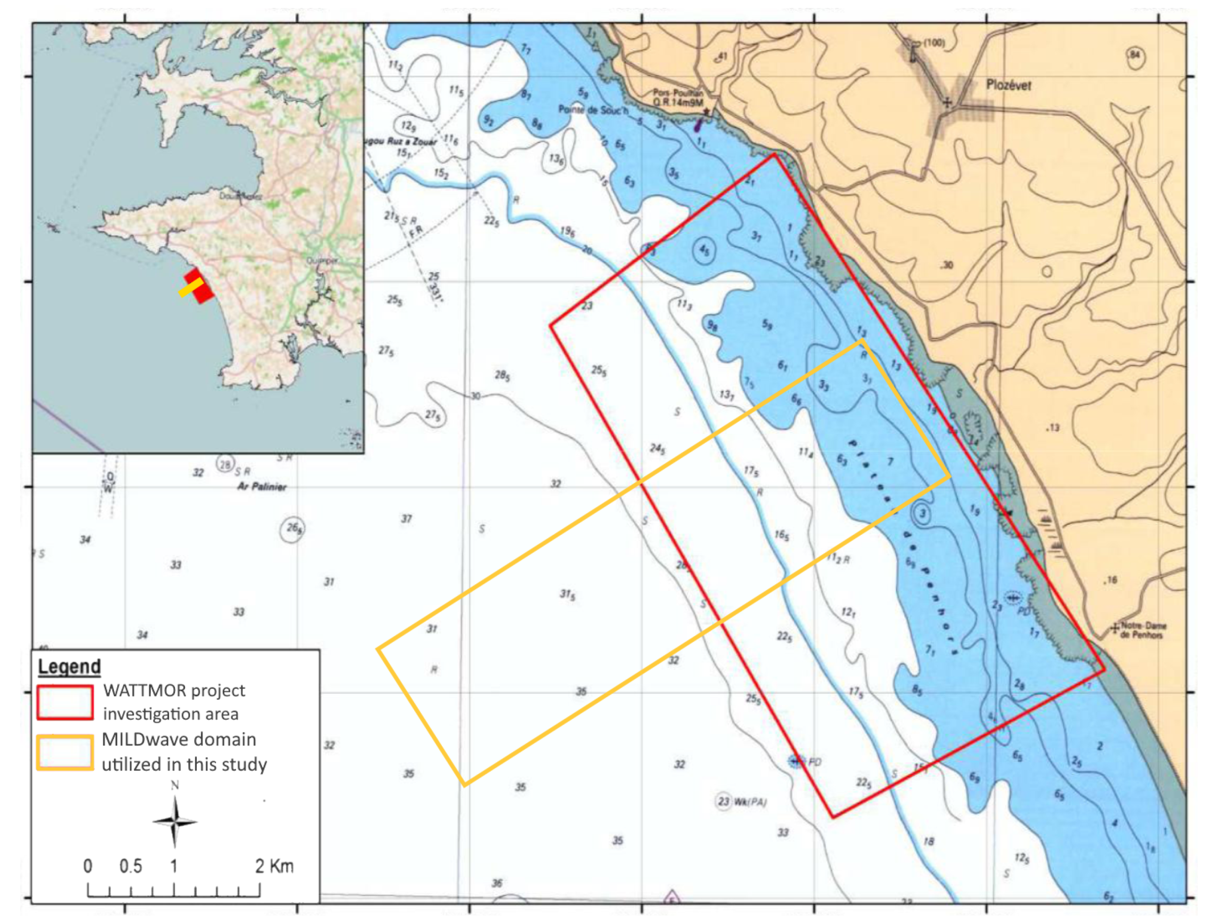
Figure 1. Map locating the investigation domain at the proposed WATTMOR project site in the Baie d’Audierne and the CANDHIS buoy 05605 (Belle-île) which serves as the source of the wave data off the coast of Bretagne, France.
Water 11 01137 g001
Figure 2. Detailed map showing the project area (red box) and the W2W model domain investigated in this study (yellow box). Point water depths are shown in meters [6].
Water 11 01137 g002
Figure 3. Map showing the detailed bathymetric survey of the project area (red box) with the present investigation domain (yellow box) overlaid [6].
Water 11 01137 g003
Figure 4. 50 WEC farm schematic shown to scale; top and side views.
Water 11 01137 g004
Figure 5. 5-WEC Array; top view.
Water 11 01137 g005
Figure 6. Schematic showing the coupling methodology domain with the MILDwave Empty Basin on the left and the coupled NEMOH-MILDwave perturbed wave run. SL indicates the sponge layer as in Section 2.3 and λ m a x is the simulated wavelength. (A) shows the Empty Basin set-up; (B) the coupled model run set-up.
Water 11 01137 g006
Figure 7. Pitching OSWEC (right) schematic. The wavy line indicates the undisturbed free surface elevation z = 0 [11].
Water 11 01137 g007
Figure 8. Hydraulic PTO system working principle of a generic OSWEC [11].
Water 11 01137 g008
Figure 9. Iterative procedure for determining the perturbed wave field for a regular wave input. Incident wave λ is coming from the left [1].
Water 11 01137 g009
Figure 10. Exploratory 10 WEC farm for validation of the wave-to-wire model. Top and side views.
Water 11 01137 g010
Figure 11. Coupled | η | for H = 2.0 T = 10.0 s and β = 0 ° regular wave for a 10 WEC 2-Array farm over a sloping bathymetry shown in Figure 10.
Water 11 01137 g011
Figure 12. Coupled absolute total wave amplitude | η | for H = 2.0 m, T = 10.0 s and β = −24 ° for a 10 WEC 2-array farm over the sloping bathymetry shown in Figure 10.
Water 11 01137 g012
Figure 13. Coupled total wave amplitude | η | for H s = 2.0 m, T p = 10.0 s and β = 0 ° regular wave for a 10 WEC 2-Array farm over a sloping bathymetry shown in Figure 10.
Water 11 01137 g013
Figure 14. Coupled | η | for H = 2.0 T = 10.0 s and β = −24 ° regular wave for a 10 WEC 2-Array farm over a sloping bathymetry shown in Figure 10.
Water 11 01137 g014
Figure 15. Coupled total | η | for the mean winter wave H m 0 = 2.55 m, T p = 11.71 s, and β = −20 ° for a 50 WEC 10-Array farm.
Water 11 01137 g015
Figure 16. Coupled total | η | for the mean summer wave H m 0 = 1.20 m, T p = 8.71 s, and β = −30 ° for a 50 WEC 10-Array farm.
Water 11 01137 g016
Figure 17. Coupled total | η | for the mean autumn wave H m 0 = 1.80 m, T p = 10.54 s, and β = −22 ° for a 50 WEC 10-Array farm.
Water 11 01137 g017
Table 1. Summary statistics of the wave climate at the Belle île measurement buoy located at 47 ° 17 N and 3 ° 17 W for a 9-year period Oct. 2010–Mar. 2019.
WinterSpringSummerAutumnYear
H s  (m)2.551.751.201.801.87
T p  (s)11.7110.458.7110.5410.34
θ m ( ° ) 261.74263.32270.12263.16264.48
Table 2. WEC farm regular wave modelled scenario.
Wave Height H (m)Wave Period T (s)Wave Incidence Angle β ( ° )
2.010.00
2.010.020
Table 3. WEC farm modelled scenarios for irregular waves.
Simulated CaseWinterSummerAutumn
H m 0  (m)2.551.201.80
T p  (s)11.718.7110.54
β  ( ° )−20.0−30.0−22.0
Table 4. Optimal hydraulic damping coefficients B P T O , h , i r r for a single OSWEC ( 10 6 × m 2 ·kg/s).
wave peak period T P (s)8.7110.5411.71
hydraulic PTO damping coefficient B P T O , h , i r r 198.7145.6121
Table 5. Power output in kW for the 50 OSWEC farm for an irregular wave of H m 0 = 2.55 m and T p = 11.71 s. Wave incidence angle β = −20 ° . Wave climate is based on the 9-year site winter mean.
Array i
Array vi
Array ii
Array vii
Array iii
Array viii
Array iv
Array ix
Array v
Array x
Total Power P farm
per Row [kW]
Total Power
P farm [kW]
743.13774.77772.83744.26733.793768.78
771.63620.77546.93585.96567.383092.676861.45
Table 6. Power output in kW for the 50 OSWEC farm for an irregular wave of H m 0 = 1.7 m and T p = 8.71 s. Wave incidence angle β = −30 ° . Wave climate is based on the 9-year site summer mean.
Array i
Array vi
Array ii
Array vii
Array iii
Array viii
Array iv
Array ix
Array v
Array x
Total Power P farm
per Row [kW]
Total Power
P farm [kW]
607.14629.09615.59621.04603.413076.27
595.74595.26489.20490.51484.222654.935731.20
Table 7. Power output in kW for the 50 WEC farm for an irregular wave of H m 0 = 1.80 m and T p = 10.54 s. Wave incidence angle β = −22 ° . Wave climate is based on the 9-year site autumn mean.
Array i
Array vi
Array ii
Array vii
Array iii
Array viii
Array iv
Array ix
Array v
Array x
Total Power P farm
per Row [kW]
Total Power
P farm [kW]
686.76699.57705.83708.32698.833499.30
699.34592.99498.44561.49546.082898.346397.64
Table 8. WEC farm q-values for the 50 WEC farm for an irregular wave of H m 0 = 2.55 m and T p = 11.71 s. Wave incidence angle β = −20 ° . Wave climate is based on the 9-year mean site winter mean.
Array i
Array vi
Array ii
Array vii
Array iii
Array viii
Array iv
Array ix
Array v
Array x
Average q-Value
per Row
Average q-Value
Farm
0.930.970.970.930.920.95
0.970.780.690.740.720.780.86
Table 9. WEC farm q-values for the 50 WEC farm for an irregular wave of H m 0 = 1.7 m and T p = 8.71 s. Wave incidence angle β = −30 ° . Wave climate is based on the 9-year site summer mean.
Array i
Array vi
Array ii
Array vii
Array iii
Array viii
Array iv
Array ix
Array v
Array x
Average q-Value
per Row
Average q-Value
Farm
0.991.031.001.010.981.00
0.970.970.800.800.790.870.93
Table 10. WEC farm q-values for the 50 WEC farm for an irregular wave of H m 0 = 1.80 m and T p = 10.54 s. Wave incidence angle β = −22 ° . Wave climate is based on the 9-year site autumn mean.
Array i
Array vi
Array ii
Array vii
Array iii
Array viii
Array iv
Array ix
Array v
Array x
Average q-Value
per Row
Average q-Value
Farm
0.910.930.940.940.930.93
0.930.790.660.750.730.770.85