Review

A Review of Hardware-in-the-Loop Applications in Coordinating Emission Control and Energy Efficiency in the Automotive Sector


1
CATARC Automotive Test Center Co., Ltd., Tianjin 300300, China
2
College of Environmental Science and Engineering, Nankai University, Tianjin 300036, China
3
Guangxi Yuchai Machinery Co., Ltd., Yulin 537000, China
4
Chinese Research Academy of Environmental Sciences, Beijing 100012, China
5
Institute for Transport Studies, University of Leeds, Leeds LS2 9ND, UK
*
Authors to whom correspondence should be addressed.
Atmosphere 2026, 17(8), 717; https://doi.org/10.3390/atmos17080717
Submission received: 15 April 2026 / Revised: 23 June 2026 / Accepted: 30 June 2026 / Published: 23 July 2026
(This article belongs to the Section Air Pollution Control)

Abstract

Hardware-in-the-loop (HIL) technology combines physical hardware with virtual models to achieve efficient closed-loop simulation of automotive systems, demonstrating significant advantages in the development of automotive emissions and energy consumption. This paper reviews the current applications of three HIL technologies, including powertrain-in-the-Loop (PIL), engine-in-the-Loop (EIL), and Virtual Test Bed (VTB). It also explores their role in addressing the increasingly stringent regulations on emissions and energy consumption. Research indicates that PIL technology can significantly improve the efficiency with which hybrid powertrain control strategies are verified by integrating real powertrains with virtual environments. EIL technology enables the high-precision simulation of real-world emissions at low hardware cost. VTB technology, meanwhile, significantly reduces the calibration period by leveraging high-precision models and intelligent algorithms. These three technologies form a comprehensive development and verification chain, covering everything from components to vehicles. However, HIL technology still faces challenges relating to model accuracy, system complexity and cost. Therefore, the most suitable technology should be selected based on development objectives, timeframe, and budget.

1. Introduction

In recent years, with the growing national emphasis on energy conservation and emission reduction, China’s regulatory framework for vehicle fuel consumption and pollutant emissions has undergone continuous and increasingly stringent upgrades. In 2016 and 2018, the China VI emission standards for light-duty and heavy-duty vehicles were officially published [1,2]. Compared with the China V standards, the China VI regulations not only introduced substantially lower limits for nitrogen oxides (NOx) and particulate matter (PM), but also incorporated particle number (PN) limits, and tightened requirements for emission durability and on-board diagnostic (OBD) systems. Moreover, the regulations mandated whole-vehicle emission testing, including real driving emission (RDE) tests and compliance limits, to ensure emission conformity under real-world driving conditions [3]. Globally, similar regulatory tightening is taking place. The United States released new emission regulations for heavy-duty engines and vehicles in 2022, and the Euro VII standards were officially issued in 2024 [4]. China has also initiated research on its forthcoming Stage VII standards for both light-duty and heavy-duty vehicles. Jing et al. [5] highlighted that future emission regulations will increasingly emphasise real-world operation conditions—such as low-load, idling, and cold-start scenarios—and will further integrate greenhouse gas (GHG) and conventional pollutant control for coordinated mitigation. In parallel, China has successively introduced the Phase V fuel consumption standards for light-duty vehicles (2021) and the Phase IV standards for heavy-duty vehicles (2025) [6,7]. Similarly, Europe and the United States have issued long-term carbon-neutrality strategies for the automotive sector [8], such as the European Union’s Fit for 55 package and California’s Advanced Clean Fleets Regulation. These developments collectively necessitate a deeper level of co-optimisation of emissions and fuel economy in vehicle design and development, while maintaining safety and performance requirements.
Hardware-in-the-loop (HIL) refers to a closed-loop simulation approach in which selected physical hardware subsystems are integrated into virtual models to emulate the behaviour of an entire system [9,10]. With its notable advantages—such as cost efficiency, reduced safety risks, shortened development time, and enhanced testing efficiency—HIL has found extensive applications across aerospace, automotive, marine, and defence industries [11]. In the automotive field, HIL technology is widely adopted in control system development and fault diagnosis processes. Its typical applications include the design, calibration, and validation of electronic control units (ECUs) for engines and transmissions, as well as the development of braking and vehicle stability control systems. By doing so, HIL greatly reduces reliance on physical prototypes, accelerates development processes, and enhances overall testing efficiency [12,13,14].
Currently, the main HIL-based methodologies that support or partially support emission–fuel economy co-optimisation include powertrain-in-the-loop (PIL), engine-in-the-loop (EIL), and virtual test bed (VTB) techniques. This paper provides a comprehensive review of these three approaches, focusing on their current applications and development trends, to offer technical insights for the automotive industry in meeting increasingly stringent emission and fuel consumption standards. The relevant literature was identified from Web of Science, CNKI, SAE Technical Papers, IEEE Xplore, and other relevant academic and technical sources. The literature search focused mainly on publications from the past ten years, with particular attention to studies related to powertrain testing and vehicle development. Search terms included combinations of “PIL”, “EIL”, “VTB”, “HIL”, “powertrain-in-the-loop”, “engine-in-the-loop”, “virtual test bench”, “hardware-in-the-loop”, “fuel economy”, “emissions”, and “vehicle development”. Studies were included if they discussed the principles, applications, development trends, or technical challenges of PIL, EIL, or VTB methods, particularly in relation to fuel consumption evaluation and emission control. Studies were excluded if they were not directly related to automotive powertrain testing, fuel economy, or emissions, or if their technical relevance to PIL, EIL, or VTB was limited. This selection strategy was used to define the scope of the review and support a focused discussion of these testing approaches.
Compared with existing reviews that mainly focus on general HIL testing, ECU validation or individual powertrain simulation methods, this review provides a focused synthesis of PIL, EIL and VTB technologies from the perspective of coordinated emission control and energy-efficiency optimisation. Its added value lies in comparing the three methodologies within a unified development chain, clarifying their respective application boundaries, and identifying unresolved challenges related to model accuracy, validation consistency, cross-study comparability, electrified powertrain applicability and real-world correlation.

2. Overview of HIL Applications in the Automotive Field

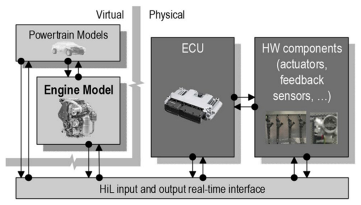
The verification of the effectiveness of vehicle functions primarily relies on numerical simulation and real-vehicle testing. However, both of these approaches have inherent limitations: simulation models often lack the fidelity required to accurately represent real-world conditions, and physical vehicle tests are costly and pose potential safety risks [15]. HIL testing combines the strengths of both methods, providing high efficiency, low cost and improved safety. Supporting automated testing under multiple operating conditions, it can be flexibly adapted to various test requirements, significantly improving the comprehensiveness and reliability of validation processes. In addition, semi-physical and fully virtual simulation technologies are gradually replacing traditional physical testing methods, such as on-road and chassis dynamometer tests, in the field of engine and vehicle emission and fuel economy development [16]. Figure 1 summarises the evolution of testing methodologies. By simulating real operating conditions through virtual models, these approaches effectively reduce the time and economic costs associated with bench and on-road testing, providing a practical and efficient solution for improving testing efficiency.

2.1. Powertrain-in-the-Loop

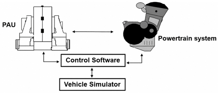
PIL is a testing methodology that integrates real powertrain hardware components—such as engines, electric motors, transmissions, and batteries—with virtual vehicle and environmental models through a real-time simulation platform [17,18,19], as illustrated in Figure 2 [16]. Traditional testing methods often struggle to capture the complexity of real-world driving conditions, while purely virtual simulations are limited by model accuracy and uncertainties in design boundaries [20]. The PIL system overcomes this issue by combining parameterised vehicle models with automated test benches, allowing for the accurate evaluation of powertrain performance. PIL is particularly advantageous for developing hybrid powertrain control strategies, analysing the correlation between emission results and test conditions, and optimising drivetrain matching [21,22].
In 2011, Tavares et al. [23] established a hydraulic powertrain-in-the-loop (H-PIL) experimental platform to investigate the effects of transient operating conditions on diesel engine emissions and fuel economy. By integrating real-time simulation with hardware-in-the-loop testing, the study demonstrated that hydraulic hybrid powertrain systems can effectively reduce engine transient events, thereby significantly decreasing pollutant emissions. Moreover, the results revealed that conventional steady-state emission prediction methods may substantially underestimate the transient emissions observed during real driving cycles. For example, particulate matter (PM) emissions were found to be 1.8 times higher than the predictions based on steady-state conditions. Liu et al. [24], referring to AVL’s evaluation of vehicle development testing methodologies, reported that the use of HIL technology, particularly PIL systems, is expected to increase substantially, whereas reliance on real-world road testing is expected to decline.
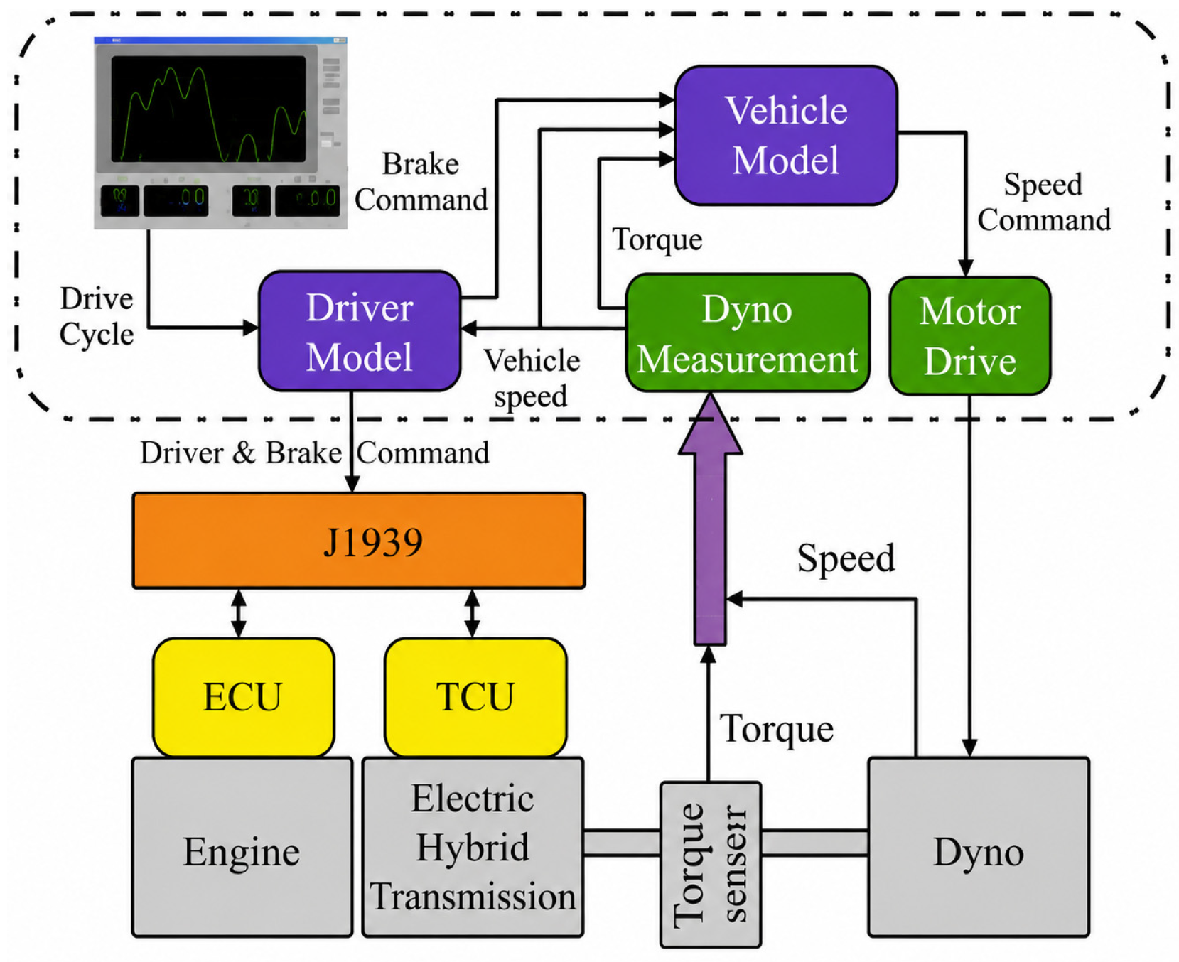
The research team further developed an independently designed powertrain-in-the-loop testing platform, through which a simulation environment incorporating complex road conditions in the Graz region of Austria was established and subsequently validated against real-vehicle road tests. The experimental results showed that the relative error between the simulated and on-road fuel consumption data was just 2.4% [25], thereby verifying the reliability and engineering applicability of HIL-based simulation for fuel economy testing. During the same period, Andreae et al. [26,27] proposed a standardised powertrain testing methodology based on the US EPA’s heavy-duty transient Federal Test Procedure (FTP) and Supplemental Emission Test (SET) cycles. The method introduced a “residual power” correction factor to adjust engine load, ensuring consistency between simulation and real-world conditions. The simulation platform is illustrated in Figure 3. Their findings indicated that dual-clutch transmissions exhibited superior performance compared with automated manual transmissions under transient operating conditions.
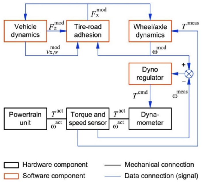
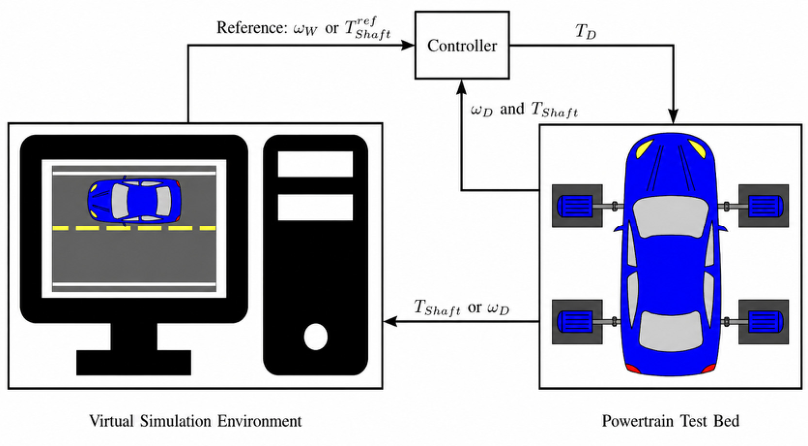
In 2021, Kulikov et al. [28] developed a Component-in-the-Loop (CIL) testing method for all-wheel-drive hybrid powertrain systems. The method enabled dynamic performance evaluation under complex driving conditions by integrating real powertrain hardware with a high-fidelity vehicle dynamics model that included tyre slip and trajectory motion simulation. The study proposed an innovative “virtual inertia” synchronisation control strategy, which accurately reproduced transient load characteristics such as vehicle acceleration and steering manoeuvres through closed-loop control of dynamometer torque and speed, as shown in Figure 4. Experimental results indicated that the system achieved a vehicle speed tracking error of less than 2 km/h during urban driving cycle simulations, while effectively capturing the energy distribution characteristics of the hybrid system under tyre slip conditions. Furthermore, the study demonstrated the potential of CIL technology in optimising all-wheel-drive system efficiency and reducing emissions, for example, by dynamically adjusting front and rear axle torque distribution to minimise energy losses under high-slip conditions.
In 2024, Erdogan et al. [29] systematically compared three PIL control strategies in their study. The speed-based control approach exhibited strong robustness against communication delays, whereas the torque-based control strategy performed better under limited actuator accuracy. Moreover, the enhanced torque control method, which integrates both feedforward and feedback mechanisms, significantly improved control accuracy under dynamic operating conditions, as illustrated in Figure 5. The research team validated the effectiveness of these control strategies through high-dynamic test scenarios, such as rapid acceleration and ABS braking. Among them, the enhanced torque control strategy maintained test errors within 5%, providing more reliable experimental data for emission and fuel consumption testing. Notably, the study successfully simulated braking conditions on low-adhesion surfaces, which holds significant implications for investigating brake energy recovery and particulate emissions. The authors further emphasised that, with the advancement of vehicle electrification, innovations in distributed testing platforms and time-delay compensation enabled by PIL technology will offer new solutions for emission testing of intelligent and connected vehicles.
Since 2011, the China Automotive Technology and Research Centre has conducted research on bench-based in-the-loop simulation technologies. Zhang et al. [30] established a Range-Extended Hybrid Powertrain PIL system on an AVL dual-dynamometer test bench, using a high-voltage battery simulator to replace the physical traction battery. By integrating a virtual Hybrid Control Unit (HCU) with the real powertrain, the system enabled closed-loop verification of vehicle-level energy consumption and emission-related control strategies. The system was evaluated through 627 functional test cases, which comprehensively assessed the impact of key strategies such as energy recuperation, range extender start–stop and power point switching on fuel consumption and emissions. It successfully identified defects in the control strategy and optimised the control logic. This demonstrates that PIL technology can support the precise development and validation of the emission and fuel economy performance of new energy vehicles in a highly repeatable and low-risk laboratory environment.
Che et al. [31] developed an efficient virtual testing environment for ECU development by simulating sensor signals and actuator loads, which significantly shortened the development period and improved system reliability. The developed test system supports the simulation and verification of various powertrain ECUs, making it particularly suitable for optimising emission and fuel consumption control strategies. Liu et al. [32] demonstrated that PIL technology can precisely optimise control strategies for fuel injection, EGR, and aftertreatment systems, thereby effectively reducing NOx and PM emissions. Combined with real-time simulation, it further enhances fuel economy. This technique is applicable to both conventional and hybrid powertrains for emission and energy efficiency evaluation, providing critical technical support for compliance with increasingly stringent emission regulations. With the integration of high-fidelity models and intelligent algorithms, PIL is expected to play an even more significant role in low-carbon powertrain development. Liu et al. [33] established a virtual–real integrated testing platform by combining a two-wheel chassis dynamometer with a HIL bench to validate the functional and performance characteristics of electric vehicle powertrain systems in a virtual full-vehicle environment. The tested powertrain system consists of a motor, motor controller, reducer, and half-shafts; the two-wheel dynamometer—comprising dynamometers and a control system—provides road load simulation; and the HIL bench serves as a virtual simulation system, incorporating environmental models to emulate the vehicle control unit and driver behaviour. The results showed that the deviation between bench simulation and real-vehicle tests was less than 5%, with a maximum deviation of only 2.65% during coasting energy recovery tests. This platform not only shortens the validation period but also improves test reliability and safety. The study demonstrates that virtual–real hybrid testing technology holds great potential for overcoming the limitations of traditional testing methods. Guan et al. [34] developed a powertrain-in-the-loop testing system to address the issues of strong environmental dependence and low efficiency in hybrid vehicle powertrain testing. The system enables real-time interaction between a virtual full-vehicle model and hardware components, integrating HIL technology with traditional bench testing to realise laboratory simulation of extreme driving conditions, such as split-friction surfaces (e.g., ice–asphalt roads). The results showed that the deviation in dynamic performance indicators between in-loop testing and real-vehicle tests did not exceed 15%, demonstrating the effectiveness of this technology in improving testing efficiency and safety, and providing a novel approach for vehicle development and validation.
Overall, the reviewed studies demonstrate that PIL technology provides a balance between physical realism and simulation flexibility. While most studies reported satisfactory accuracy for fuel-consumption and emission prediction, the effectiveness of PIL remains dependent on plant-model fidelity and real-time communication performance. Recent developments further indicate a growing application of PIL in electrified and hybrid powertrain systems. While PIL focuses on validating interactions between real powertrain hardware and virtual vehicle environments, further investigation of engine-specific emission behaviour requires a more dedicated engine-centred framework. Therefore, EIL technology has emerged as a complementary approach for engine calibration, transient emission analysis, and RDE-oriented development.

2.2. Engine-in-the-Loop

EIL is a hardware-in-the-loop testing methodology in which a real engine is employed as physical hardware, while virtual models simulate the entire vehicle system and driver behaviour. This setup enables the development and optimisation of full-vehicle performance directly on an engine test bench. Through modelling driving cycles and driver actions, EIL effectively eliminates disturbances arising from driver habits, traffic conditions, and environmental factors in real-world testing, thereby ensuring consistency and repeatability of test conditions. This technology not only allows early-stage validation of engine–vehicle integration and performance matching but also significantly improves development efficiency and reduces real-vehicle testing costs, making it highly valuable for powertrain optimisation and emission control strategy verification.
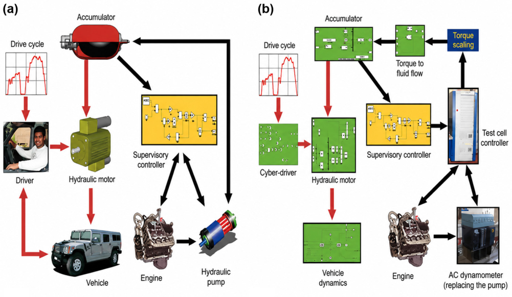
In 2010, Filipi and Kim et al. [35] integrated a real engine with a virtual vehicle model to evaluate a hydraulic hybrid propulsion system for a medium-duty truck (see Figure 6). Under an urban city driving schedule, and using a modulated state-of-charge control strategy that favoured regenerative energy recovery, the hydraulic hybrid configuration achieved a 72% reduction in fuel consumption and a 74% reduction in particulate emissions relative to a conventional baseline vehicle. These results are specific to the investigated hydraulic hybrid architecture and urban operating conditions and should not be generalised to conventional ICE powertrains, mild hybrid systems, or all HIL-assisted development cases.
A study by Bosch Engineering [36] showed that the EIL platform allows RDE development to be started earlier in a project. This reduces the need for prototype vehicles by 85% and improves efficiency by completing six automated tests within 24 h. This technology successfully reproduced the NOx emission increase caused by the drop in SCR system temperature during congested driving conditions, and quantified the influence of different driving styles on emissions. Moreover, the high repeatability of the EIL platform provides reliable data for fuel optimisation and offers essential technical support for meeting stringent emission regulations.
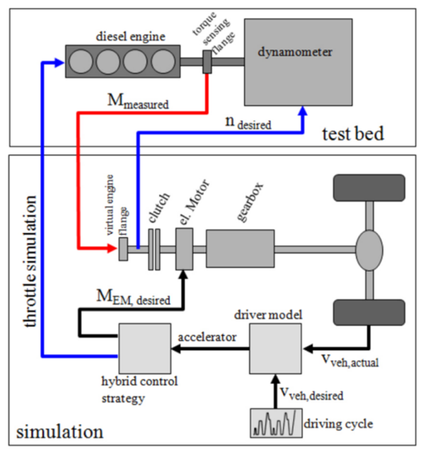
Teiner et al. [37] from the Vienna University of Technology found that the EIL platform enables the precise testing of parallel diesel hybrid systems, where the implementation of intelligent control strategies resulted in a 35% reduction in NOx emissions and a 15% decrease in fuel consumption. The study compared different hybrid configurations, including the Integrated Starter-Alternator Mild Hybrid (ISAMH) and the Single-Clutch Parallel Full Hybrid (SCPFH), and revealed that the SCPFH configuration performed better in emission and fuel economy optimisation due to its capability for pure electric driving and efficient energy recovery. Through real-time interactive closed-loop control, the EIL technology effectively avoids the issue of insufficient model accuracy in traditional simulations, as shown in Figure 7.
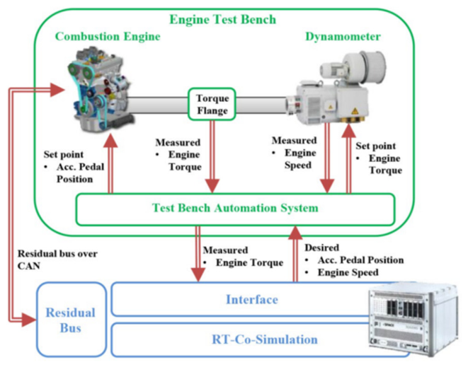
As shown in Figure 8, Klein et al. [38] used an EIL test bench to evaluate a 48 V mild-hybrid system with a belt-driven starter generator in a P0 layout. Under WLTC and RDE cycles, this configuration reduced particulate number by 38–40% and fuel consumption by 3.2–3.8% relative to the corresponding 12 V baseline. These values are specific to the investigated 48 V mild-hybrid architecture, WLTC/RDE test conditions and EIL validation approach, and should therefore not be directly compared with reductions reported for hydraulic hybrid systems or other powertrain architectures.
Takahata et al. [39] investigated the critical role of EIL technology in the design of emission performance for hybrid powertrain systems. The study established a closed-loop EIL system by integrating a real engine with a virtual vehicle model, enabling the prediction of full-vehicle emissions and the optimisation of control strategies. The results indicated that the EIL system could reproduce actual vehicle emission behaviour with high accuracy. The prediction errors for NOx and THC emissions were within 11% and 15%, respectively, while the CO2 emission error was only 1.6%. Furthermore, EIL technology supports catalyst warm-up control and combustion parameter optimisation, significantly enhancing the effectiveness of achieving emission targets.
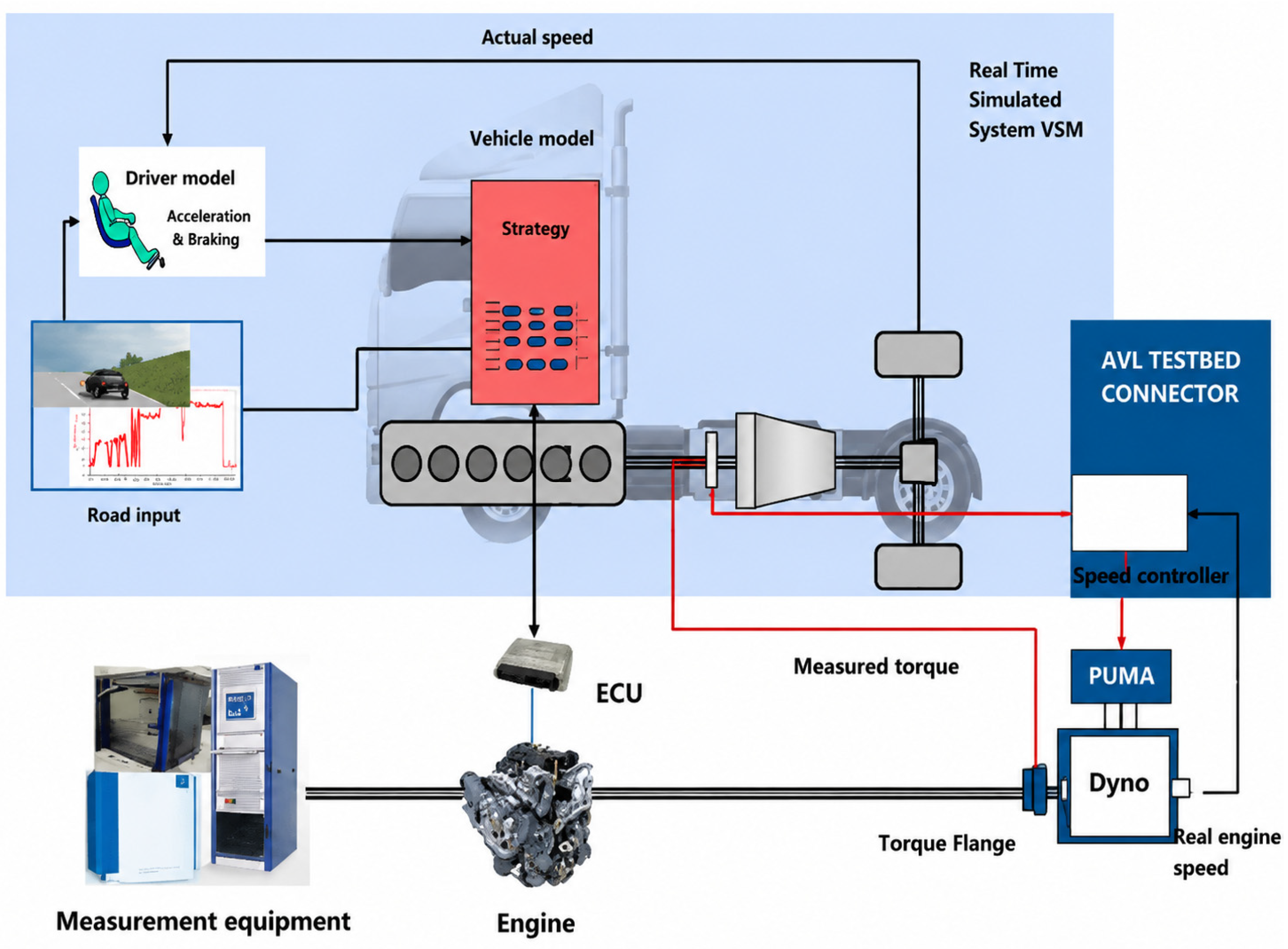
In China, Wang et al. [40,41,42,43,44,45] employed engine-in-the-loop techniques combined with a single-factor sensitivity analysis to address the challenges of decoupling the effects of emissions, fuel consumption, and complex influencing factors. The EIL platform used is shown in Figure 9. Their system systematically investigated the influence of vehicle load, driving behaviour, cold start, air conditioning, environmental conditions, and traffic scenarios on the real-world emissions and fuel consumption of heavy-duty vehicles, enabling a quantitative assessment of the impact of individual variables on energy use and emissions. Furthermore, they applied the EIL approach to analyse low-load operating conditions and PN10 emissions under anticipated future emission standards. EIL-based studies [46] explored NOx emission characteristics under low-load cycles (LLCs), comparing the differences between full-vehicle LLCs and engine LLCs, and found that vehicle loading has a significant impact on NOx conversion efficiency and final emissions. Therefore, in low-load condition development—especially when converting from vehicle-level to engine-level cycles—load settings must be carefully considered. In [47], EIL technology was used on engine test benches to study real-world fine particulate (PN10) emissions from heavy-duty diesel vehicles, overcoming the lack of on-board PN10 measurement devices and providing first-hand data on fine particulate emissions under real driving conditions, effectively supporting the formulation of future emission standards.
Collectively, these studies indicate that EIL offers higher engine and emission fidelity than conventional simulation-based approaches. Its major advantage lies in reproducing transient combustion and after-treatment behaviour under controlled laboratory conditions. However, its applicability to fully electric vehicles remains limited because the methodology is inherently centred on physical engine hardware. Compared with PIL and EIL, which still rely on physical hardware components, VTB further increases the level of virtualisation by shifting much of the calibration and optimisation process into high-fidelity digital environments. This enables earlier design exploration and substantial reductions in testing effort.

2.3. Virtual Test Bed

VTB technology is an advanced HIL-based calibration approach that leverages high-fidelity digital simulations to replicate the operational characteristics of physical systems. By enabling parameter optimisation of key components such as engines, transmissions, and hybrid powertrain systems, VTB reduces reliance on conventional physical testing and offers significant advantages in terms of reducing test volume, shortening development period, and lowering costs [48,49].
Because HIL-based virtual calibration systems can simulate the real-time states of target models, the calibration process closely approximates real-world conditions, attracting wide attention from both domestic and international enterprises. For instance, AVL has successfully developed a HIL-based virtual calibration platform and applied it to the calibration of engine controllers and hybrid system controllers [50]. The VTB integrates modelling and calibration software such as Cruise M and INCA with physical hardware, including real controllers, real-time simulation systems, and dSPACE HIL systems. Practical applications indicate that replacing traditional calibration test benches with a VTB system can save up to 80% of calibration time [51].
Real-time simulation models constitute the core of HIL testing technology, while the V-Model offers advantages such as parallel development, stage-corresponding verification, and a comprehensive toolchain, effectively reducing development errors and improving efficiency [52,53]. Consequently, the V-Model has become the mainstream methodology for electronic control system development and is equally applicable to HIL system development processes, which typically include requirements analysis and system design, rapid prototyping validation, code generation, HIL testing, and system integration and calibration [54,55].
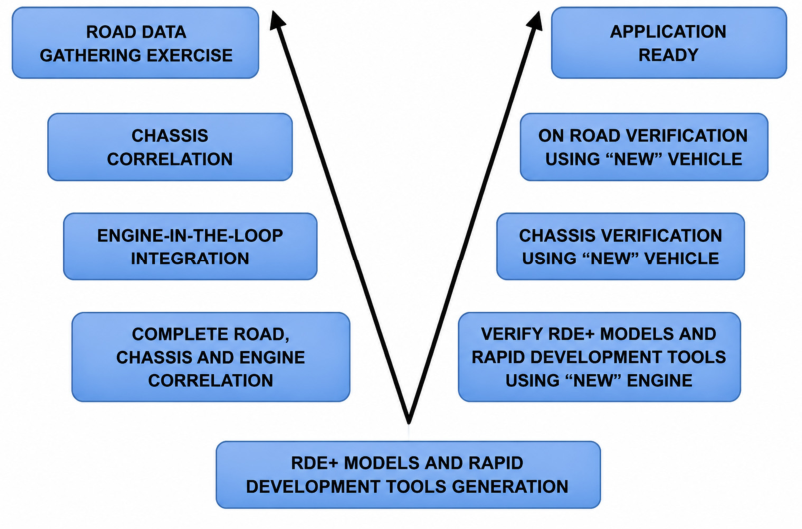
In a virtual calibration framework oriented toward future emission regulations, HORIBA MIRA [56] proposed the RDE Plus (RDE+) approach, providing a systematic paradigm for achieving road–rig–engine-in-the-loop (R2R-EiL) consistency verification of full vehicles and powertrain systems in the early development stage, as shown in Figure 10. The study used multi-location, multi-climate real-world RDE data from Europe and employed high-fidelity chassis dynamometer reproduction techniques to reconstruct road loads, including gradient, ambient temperature and altitude, and map them to laboratory conditions. Subsequently, a virtual vehicle model was coupled with a real engine via the EIL platform to conduct DoE-based calibration optimisation under legally defined “extreme” boundary conditions. In alignment with the V-Model development process, the method achieved less than 3.8% error between road and test rig measurements for cumulative CO2, positive work indices, and thermal state parameters. Moreover, by front-loading virtual operating conditions, the approach substantially reduced the number of prototype vehicle tests and shortened the development period, thereby demonstrating the engineering feasibility of virtual calibration for achieving RDE compliance and reducing calibration costs for fuel consumption and emissions.
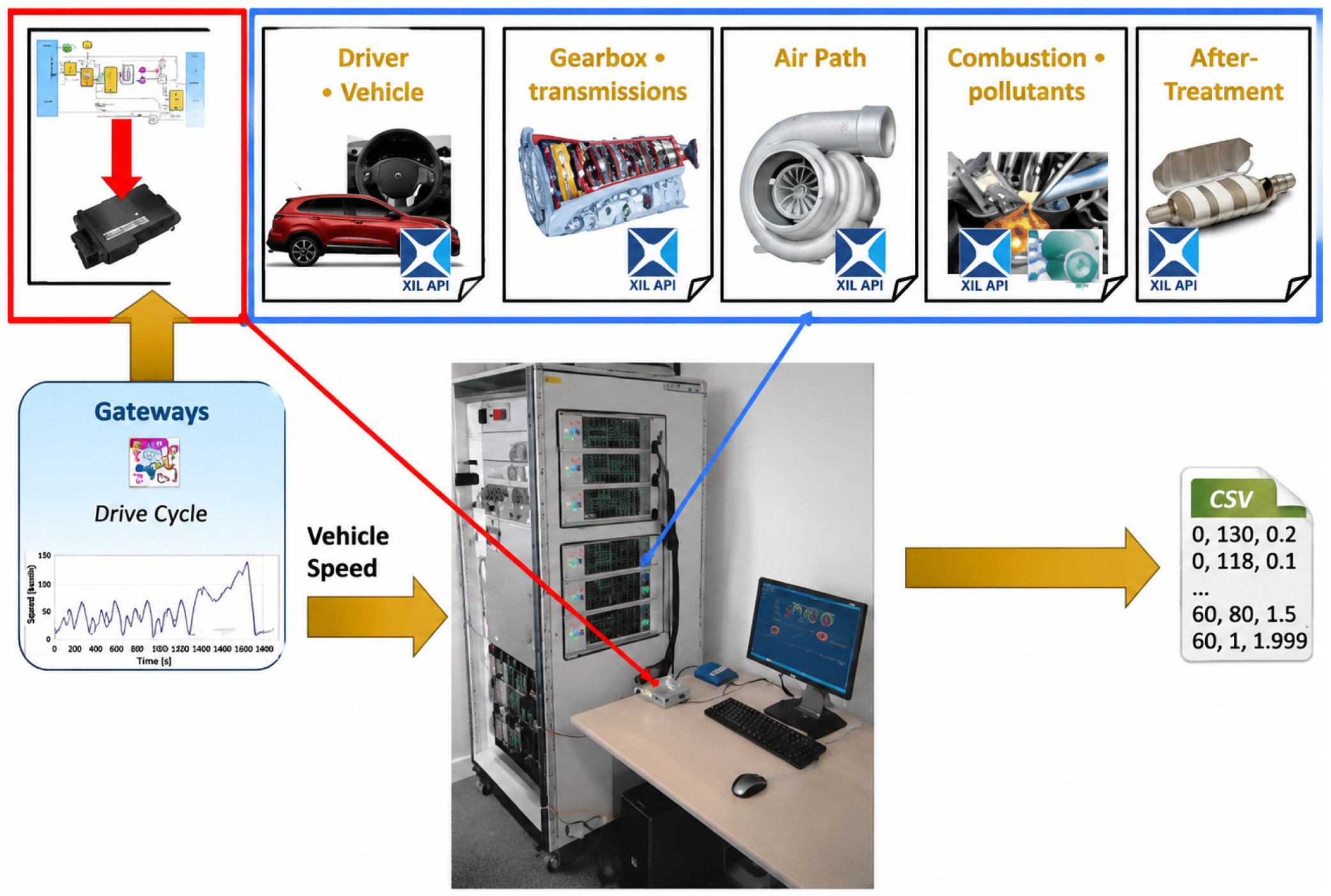
Maroteaux [57] proposed a HIL-based Virtual Chassis Dynamometer (VCD) approach, which integrates a physical model of the air path with a statistical model of combustion and emissions to achieve high-fidelity simulation of diesel engine emissions and fuel consumption. The test platform is illustrated in Figure 11. The study demonstrated that this approach can accurately predict engine emissions—including NOx, PM, HC, and CO—under both steady-state and transient operating conditions, with cumulative errors controlled within 5%, and can effectively reproduce the impact of calibration parameter variations on emissions. Furthermore, by extending Design of Experiments (DoE) to cover high-altitude air–fuel ratio conditions, the robustness of the model under transient conditions was further enhanced, providing a valuable reference for the application of virtual calibration technologies in meeting real-driving emission requirements.
Lee et al. [58] proposed a scalable Mean Value Modelling (MVM) approach to enable real-time virtual calibration of engines within a HIL environment, addressing increasingly stringent RDE regulatory requirements. The test bench configuration is shown in Figure 12. The study systematically compared two modelling strategies: (1) a physically based full MVM method combined with a semi-physical emissions model, and (2) an approach integrating MVM with a Design-of-Experiments (DoE)-based Gaussian Process model to predict in-cylinder combustion and emission behaviour. Results indicated that both strategies could accurately predict engine emissions (e.g., NOx) and fuel consumption across various transient driving cycles, exhibiting high consistency and scalability, and were particularly suitable for virtual calibration tasks when complete engine test data were unavailable. These findings provide strong support for the application of virtual calibration-in-the-loop techniques in real-vehicle emission and fuel consumption optimisation, highlighting their significant contribution to shortening the development period and reducing testing costs.
Wang et al. [59] investigated the robustness of diesel engine fuel consumption and NOx emissions using virtual calibration techniques, revealing the influence of exhaust bypass valve opening characteristics and Venturi tube differential pressure signal offsets on engine performance. The study demonstrated that a positive shift in the exhaust bypass valve opening characteristics increased pumping losses under high-load conditions, leading to a significant deterioration in fuel consumption. Meanwhile, offsets in the Venturi tube differential pressure signal directly affected NOx emissions by altering EGR flow, with a 4 kPa offset resulting in an 8.61% increase in emissions. This work validated the effectiveness of HIL technology for analysing the impact of critical parameters on emissions and fuel consumption, providing a low-cost, efficient solution for engine calibration and fault diagnosis. Gao et al. [60] proposed an automated control parameter calibration method for plug-in hybrid buses based on driving conditions, employing orthogonal experiments and optimisation algorithms to construct a real-time simulation platform. The results indicated that this method reduced fuel consumption by 12.30% while maintaining vehicle performance and improved calibration efficiency by 75.51% compared with manual methods. Ning et al. [61] conducted a virtual calibration study for hybrid-specific transmissions using an HIL platform. A high-fidelity model integrating hydraulic, mechanical, and control strategies was developed, and key parameters such as clutch pressure and target engine speed were calibrated under creeping and start-up conditions. The study showed that parameters obtained from virtual calibration were highly consistent with conventional in-vehicle calibration data, significantly shortening the vehicle development period and effectively improving start-up smoothness and response.
Moreover, Yu [62] proposed a deep neural network-based virtual calibration method. By constructing a surrogate model of the powertrain system and applying Sobol index-based sensitivity analysis, the method significantly enhanced the fuel economy and emission performance of hybrid vehicles. The results demonstrated that the method achieved a 14.62% reduction in equivalent fuel consumption per 100 km, a 23.81% decrease in engine start–stop events, and a 14.17% reduction in power battery capacity loss, with errors controlled within 10%. This study provides valuable insights for the application of virtual calibration techniques in automotive emission and fuel consumption optimisation, particularly demonstrating high calibration efficiency and global optimisation capability in multi-parameter, strongly coupled hybrid powertrain systems. Zhu et al. [63] employed virtual calibration techniques to develop an emission prediction model by integrating high-fidelity engine and vehicle models with space-filling Design-of-Experiments (DoE) modelling and Gaussian algorithms, and implemented real-time computation on an HIL simulation platform. The results indicated that this approach could effectively reproduce emission characteristics, with cumulative deviations of gaseous pollutants (HC, CO, NOx, CO2) controlled within 7.3%. Liu et al. [64] proposed an HIL-based energy management strategy optimisation method for power-split hybrid light commercial vehicles. By constructing a high-fidelity human–vehicle–road forward simulation model combined with a cooperative evolutionary particle swarm optimisation algorithm, the study achieved deep optimisation of calibration parameters. The results demonstrated that virtual calibration could effectively overcome the limitations of conventional calibration methods, including a long development period and poor adaptability, achieving a 20.90% fuel saving under typical and aggressive driving cycles. Moreover, an adaptive optimal calibration parameter-based energy management strategy was developed and validated via HIL testing, showing a reduction of overall fuel consumption by 4.93–15.14% across different operating scenarios.
In summary, VTB technology achieves the highest degree of virtualisation among the three methodologies. Compared with PIL and EIL, VTB substantially reduces calibration effort and development time, although its reliability depends strongly on model quality and cross-validation with experimental data. It should be noted that the accuracy metrics reported across different PIL, EIL and VTB studies were obtained using different validation procedures, test cycles, model boundaries and reference measurements. Therefore, these values should be interpreted as study-specific validation results rather than directly comparable standardised benchmarks. Standardised interfaces such as ASAM XIL can improve consistency in test automation and communication between test tools and HIL benches, but they do not by themselves define a universal model-accuracy criterion for all HIL applications. In addition, PIL, EIL and VTB should be regarded as complementary rather than interchangeable methodologies. PIL is suitable for powertrain-level integration and control validation, EIL provides high repeatability for engine-side transient emission and fuel-consumption studies, and VTB is more appropriate for early-stage virtual calibration and vehicle-level consistency assessment. However, the reviewed studies differ substantially in test cycles, model boundaries, reference measurements and validation procedures. Therefore, reported accuracy or cost-saving values should be interpreted as study-specific results rather than directly comparable benchmarks. Key unresolved challenges include standardised validation protocols, cross-platform comparability, BEV/FCEV applicability, real-world correlation and representation of long-term component degradation.

3. Comparison and Synergistic Application of the Three Techniques

3.1. Technical Comparison

Although PIL, EIL and VTB technologies all belong to the field of virtual testing and calibration in automotive development, they differ in terms of their testing scope, application scenarios and level of integration. Table 1 systematically summarises the differences and complementarities among PIL, EIL, and VTB. All three techniques rely on real-time simulation platforms to establish closed-loop connections between partial physical hardware and high-fidelity models, enabling low-cost and highly repeatable validation of control strategies. EIL is primarily used for engine-level control strategy verification, whereas PIL extends the approach to multi-powertrain coupling, such as in hybrid systems. Initial calibration data generated by VTB can serve as input for EIL/PIL testing, while the results from EIL/PIL can in turn refine model accuracy. In summary, EIL focuses on the engine, PIL addresses the system level, and VTB optimises calibration parameters. Together, these three techniques form a synergistic and comprehensive validation chain, spanning from component to vehicle level and from development to calibration.

3.2. Synergistic Application and Future Technological Integration

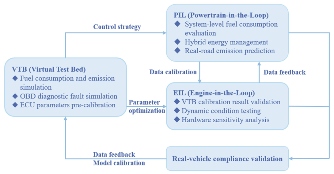
As illustrated in Figure 13, VTB leverages its powerful computational capabilities and optimisation algorithms to rapidly explore a large number of parameter combinations in a virtual environment, significantly shortening the calibration period and reducing early dependence on costly physical prototypes and test benches. EIL validates the robustness of core engine control logic and parameters in a real ECU environment before deployment to complex PIL systems or actual vehicles, allowing potential issues to be identified at an early stage. PIL subsequently verifies the impact of calibration parameters on vehicle-level performance within a system-level environment that includes real controllers, while real vehicle data serves as the ultimate reference. By continuously feeding measured data back into model calibration, a self-improving closed-loop system is established, enhancing the predictive accuracy of HIL simulations and reducing the number of subsequent vehicle tests and associated costs. Fathy et al. [65] proposed that by utilising virtual scaling and networked HIL, distributed physical hardware such as engines, transmissions, and electric motors can be synchronised into a unified virtual scenario in the cloud, enabling concurrent remote development and providing a replicable experimental paradigm for next-generation hybrid and zero-carbon powertrains. In the future, HIL technology is expected to further evolve toward intelligent, cloud-based, and high-fidelity model-integrated approaches. AI- and machine-learning-assisted calibration may provide new opportunities for improving parameter optimisation and test-case selection in virtual calibration, while cloud-based HIL platforms may support distributed hardware testing and virtual scenario co-development across locations [66,67]. However, these approaches remain emerging research directions and require further experimental validation, standardised workflows and industrial proof-of-concept studies before their general applicability can be confirmed. For BEV and FCEV applications, the applicability of different HIL methodologies needs to be reconsidered. Traditional EIL is not directly applicable to BEVs because no internal combustion engine is present. Instead, HIL architectures need to shift towards electric motor-in-the-loop, battery-in-the-loop, inverter-in-the-loop and vehicle-level virtual validation. PIL and VTB remain applicable to electrified powertrains, but require high-fidelity real-time models of electric-machine dynamics, inverter control, battery SOC/SOH, battery thermal behaviour and, for FCEVs, fuel-cell stack dynamics, hydrogen supply, air management and thermal control.
Moreover, the adaptation of novel fuels (e.g., hydrogen, e-fuels) will drive improvements in the dynamic response accuracy of EIL, while the development of multi-physics coupled models will strengthen PIL simulation capabilities for integrated electro-mechanical–thermal systems [68]. Through continuous closed-loop optimisation and real-world data feedback, HIL technology will establish a more precise and efficient development framework, providing core technical support for the automotive industry to achieve carbon-neutral targets.

3.3. Adaptation of HIL Methodologies for BEV, HEV and FCEV Platforms

Vehicle electrification has expanded the application scope of HIL testing from conventional engine-centred validation to the development of electrified and zero-emission powertrains. For HEVs, HIL remains highly relevant because the powertrain includes both combustion-engine and electric-drive subsystems. In this context, EIL can still be used to evaluate engine control, transient combustion behaviour and after-treatment responses, while PIL and VTB are required to capture interactions among the engine, electric motor, battery, transmission, regenerative braking and supervisory energy-management controller [69].
For BEVs, however, conventional EIL has limited direct applicability because there is no physical combustion engine in the powertrain. Its use would require fundamental reconfiguration, replacing the engine-centred test object with electric machines, inverters, power electronics, battery packs or battery-management systems. PIL and VTB are more suitable for BEV development, but they require accurate real-time models of electric motor dynamics, inverter switching and control behaviour, battery state of charge, battery state of health, thermal management, regenerative braking and vehicle-level energy consumption [70].
For FCEVs, HIL platforms have to further incorporate fuel-cell stack dynamics, hydrogen supply, air-management systems, humidification, thermal regulation, power buffering and hybridisation with batteries or supercapacitors. Compared with BEVs, FCEVs present additional challenges because electrochemical response, auxiliary power demand and thermal-water management are strongly coupled. Fuel-cell HIL methods have been proposed for fuel-cell and fuel-cell-system design and evaluation, while recent FCHEV studies further highlight the importance of energy-management strategies and real-world driving-cycle validation [71,72].

4. Limitations and Challenges of HIL Technology

Although HIL technology offers significant advantages in the development of automotive emissions and fuel economy, its application faces several challenges related to model accuracy, system complexity, validation, and cost [40,73].

4.1. Model Accuracy, Real-Time Performance, and Degradation Representation

HIL simulations rely on high-fidelity mathematical models and real-time computational capability. However, real-world driving conditions are difficult to reproduce fully because HIL models usually simplify complex physical processes to meet real-time requirements [74]. In hybrid powertrain HIL testing, deviations between simulated and actual vehicle performance still require further optimisation [75]. A further limitation is the insufficient representation of long-term component ageing, performance degradation, wear, and lubrication-related effects [76]. Ageing processes such as sensor drift, actuator delay, injector wear, lubricant oxidation, viscosity change, friction variation, and after-treatment deterioration are cumulative and history-dependent. They are influenced by load history, temperature exposure, contamination, maintenance conditions, and operating cycles. These processes are difficult to reproduce within short-duration real-time HIL tests without simplified empirical assumptions. Therefore, conventional HIL platforms can evaluate control performance under nominal or predefined degraded conditions, but they remain limited in predicting how long-term deterioration affects transient response, fuel consumption, and emissions. Future HIL platforms should integrate degradation maps, lubricant-property evolution models, ageing-sensitive calibration parameters, and long-term experimental validation data.

4.2. Thermal Boundary Conditions During Cold-Start and Warm-Up Transients

Another important limitation is the accurate simulation of thermal boundary conditions, especially during cold-start and warm-up operation. During these periods, engine, lubricant, coolant, exhaust, and after-treatment temperatures change rapidly, while combustion stability, friction losses, catalyst light-off, fuel consumption, and pollutant emissions are highly temperature-dependent [77,78]. If thermal inertia, heat-transfer processes, lubricant-temperature effects, and after-treatment warm-up behaviour are simplified, the HIL platform may reproduce control responses but still misrepresent emission formation and fuel-consumption behaviour under transient conditions [79]. This is particularly important for emission-control development because cold-start operation often contributes disproportionately to total emissions. Therefore, future HIL studies should place greater emphasis on coupled thermal, lubrication, combustion, and after-treatment models, together with experimental validation under transient temperature conditions.

4.3. Validation Against PEMS Data Under Real-World RDE Conditions

Validation remains a major challenge for HIL applications in emission and fuel-economy assessment. Laboratory-based HIL tests are conducted under controlled and repeatable conditions, whereas real driving emission (RDE) tests using Portable Emission Measurement Systems (PEMSs) are affected by road gradient, traffic conditions, ambient temperature, payload, driver behaviour, altitude, vehicle thermal history, and after-treatment operating state [80]. In addition, PEMS data contain measurement uncertainties related to analyser drift, exhaust-flow measurement, time alignment, instrument response, particle losses, and data post-processing. These uncertainties complicate the direct comparison between HIL outputs and real-world measurements [81]. Therefore, HIL validation should not rely only on point-by-point agreement with PEMS data, but should also consider uncertainty ranges, repeated RDE tests, representative driving cycles, and statistical comparison of emission trends.

4.4. Complexity of System Integration and Multi-Objective Optimisation

Hybrid powertrain systems involve the coordination of multiple objectives, including performance, fuel economy, emissions, drivability, battery state-of-charge control, and thermal management. HIL systems must therefore handle multi-dimensional control strategies and interactions between engines, electric machines, batteries, after-treatment systems, and vehicle-level energy-management algorithms. Although multi-objective coordination control techniques can be validated through HIL, their development and calibration require careful trade-offs between model complexity, computational efficiency, control robustness, and cost [82].

4.5. Cybersecurity and Data Integrity in Cloud-Distributed HIL Platforms

With the development of cloud-based and internet-distributed HIL platforms, new risks related to cybersecurity, data integrity, and communication reliability have emerged. Distributed HIL systems may connect geographically separated hardware, vehicle components, cloud servers, and simulation platforms [83]. Although this architecture improves flexibility and resource sharing, it also increases exposure to unauthorised access, data manipulation, communication delay, packet loss, and synchronisation errors [84]. These issues may affect not only simulation accuracy but also the reliability of calibration and validation results. Therefore, secure communication protocols, data authentication, access control, encrypted data transmission, and latency compensation should be considered in future distributed HIL development.

4.6. Cost, Development Period, and Applicability to Future Powertrains

While HIL technology can shorten the development period, constructing high-fidelity HIL systems requires substantial investment in hardware, software, model development, calibration, and specialist expertise [85,86]. As virtualised components increase, stricter requirements are imposed on model accuracy and validation. In addition, the applicability of EIL is limited for BEV and FCEV architectures because EIL is fundamentally based on a physical combustion engine. BEVs and FCEVs require different test objects, including batteries, electric machines, inverters, fuel-cell stacks, hydrogen supply systems, and thermal-management systems. Therefore, future virtual testing platforms should move beyond combustion-engine-centred EIL and develop more flexible X-in-the-loop frameworks suitable for hybrid, battery-electric, and fuel-cell powertrains. Future improvements in HIL reliability and practicality will depend on more precise model optimisation, multidisciplinary co-design, advanced simulation tools, and architecture-specific validation methods [54,87]. Rather than functioning as independent methodologies, future HIL platforms are expected to integrate PIL, EIL, and VTB within a unified X-in-the-loop framework. Such integration would enable high-fidelity hardware validation, real-time emission assessment, and large-scale virtual calibration within a single development workflow.

5. Conclusions

This review shows that PIL, EIL and VTB provide complementary rather than interchangeable functions in vehicle emission, fuel-economy and powertrain development. PIL is most suitable for component- and subsystem-level control development, especially where engine, motor, battery or transmission interactions need to be represented under repeatable boundary conditions. EIL remains particularly valuable for combustion-engine and hybrid-powertrain studies because it allows real engine behaviour, transient combustion and after-treatment responses to be evaluated within a controlled simulation environment. VTB is more appropriate for vehicle-level validation, including integrated powertrain behaviour, drivability, energy consumption and regulatory-oriented test-cycle assessment.
Several unresolved challenges remain. First, HIL accuracy is still limited by simplified thermal, ageing, lubrication, after-treatment and battery models. Second, cross-validation against engine-bench, chassis-dynamometer, vehicle-road and PEMS/RDE data remains insufficiently standardised. Third, the applicability of conventional HIL architectures to BEV and FCEV platforms requires further adaptation, particularly for electric-machine dynamics, inverter control, battery thermal management and fuel-cell system behaviour. Fourth, cloud-based and AI-assisted HIL platforms may improve flexibility and calibration efficiency, but their use introduces new concerns regarding cybersecurity, data integrity, latency and model transparency.
Future research should therefore prioritise: (i) uncertainty-aware HIL validation frameworks; (ii) improved real-time models for thermal transients, degradation and after-treatment dynamics; (iii) standardised cross-validation protocols using laboratory and real-world data; (iv) dedicated HIL architectures for BEV, HEV and FCEV platforms; and (v) cautiously evaluated AI/cloud-based HIL methods. These directions should support engineers in selecting PIL for early-stage controller development, EIL for combustion or hybrid subsystem validation, and VTB for integrated vehicle-level and regulatory-oriented assessment.

Author Contributions

Conceptualization, X.W., T.G., Y.C. and Y.L.; methodology, X.W., T.G. and G.H.; validation, L.Z. and T.G., Y.L. and M.W.; formal analysis, X.W. and T.G.; investigation, T.G. and M.W.; data curation, G.H., Y.C. and T.G.; writing—original draft preparation, X.W., T.G. and Y.L.; writing—review and editing, Y.C., G.H., T.L., L.Z. and M.W.; supervision, M.W., Y.C. and X.W.; project administration, X.W. and M.W.; funding acquisition, X.W. All authors have read and agreed to the published version of the manuscript.

Funding

This work was supported by the Open Fund of the State Key Laboratory of Engine and Powertrain Systems (No. skleps-sq-2025-124).

Data Availability Statement

The raw data supporting the conclusions of this article will be made available by the authors on request.

Conflicts of Interest

Authors X.W., T.G., T.L. and L.Z. were employed by the company CATARC Automotive Test Center Co., Ltd. Author G.H. was employed by the company Guangxi Yuchai Machinery Co., Ltd. The remaining authors declare that the research was conducted in the absence of any commercial or financial relationships that could be construed as a potential conflict of interest.

References

  1. GB 18352-2016; Limits and Measurement Methods for Emissions from Light-Duty Vehicles (China 6). Ministry of Ecology and Environment of the People’s Republic of China: Beijing, China, 2016.
  2. GB 17691-2018; Limits and Measurement Methods for Emissions from Diesel-Fuelled Heavy-Duty Vehicles (China VI). Ministry of Ecology and Environment of the People’s Republic of China: Beijing, China, 2018.
  3. Ding, L.; Zou, X.H.; Dai, C.B.; Liu, L.; Qin, H.Y. Comparison of the Difference between China VI and China V Emission Standards of Light Vehicles. Small Intern. Combust. Engine Veh. Tech. 2019, 48, 54–59. (In Chinese) [Google Scholar]
  4. European Parliament and Council. Regulation (EU) 2024/1257 of the European Parliament and of the Council: On Type-Approval of Motor Vehicles and Engines and of Systems, Components and Separate Technical Units Intended for Such Vehicles, with Respect to Their Emissions and Battery Durability (Euro 7); European Parliament and Council: Brussels, Belgium, 2024. [Google Scholar]
  5. Jing, X.J.; Ren, S.J.; Wang, X.W.; Li, T.T.; Fang, M.D. Basic ideas and development trend of heavy-duty vehicle emission regulations in next stage. J. Automot. Saf. Energy 2023, 14, 133–156. (In Chinese) [Google Scholar]
  6. GB 19578-2021; Fuel Consumption Limits for Passenger Cars. Ministry of Ecology and Environment of the People’s Republic of China: Beijing, China, 2021.
  7. GB 30510-2024; Fuel Consumption Limits for Heavy-Duty Commercial Vehicles. Ministry of Ecology and Environment of the People’s Republic of China: Beijing, China, 2024.
  8. Shi, S.K.; Zhang, X.N. Research on the CO2 Emission Regulations for Heavy-Duty Vehicles in EU and USA and Suggestions for China. China Auto 2024, 8, 3–8. (In Chinese) [Google Scholar]
  9. Isermann, R.; Schaffnit, J.; Sinsel, S. Hardware-in-the-loop simulation for the design and testing of engine control systems. Control Eng. Pract. 1999, 7, 643–653. [Google Scholar] [CrossRef]
  10. Wang, X.W.; Ling, J.; Yan, F. Review on Engine-in-the-loop Simulation: Application and Development. Small Intern. Combust. Engine Veh. Tech. 2019, 48, 79–84. (In Chinese) [Google Scholar]
  11. Anakwa, N.; Roca, P.; Lopez, J.; Malinowski, A. Environments for rapid implementation of control algorithms and hardware-in-the-loop simulation. In Proceedings of the 2002 28th Annual Conference of the IEEE Industrial Electronics Society, Seville, Spain, 5–8 November 2002; Volume 3, pp. 2288–2293. [Google Scholar]
  12. Raman, S.; Sivashankar, N.; Milam, W. Design and implementation of HIL simulators for powertrain control system software development. In Proceedings of the American Control Conference, San Diego, CA, USA, 2–4 June 1999; pp. 709–713. [Google Scholar]
  13. Schupbach, M.; Balda, C. A versatile laboratory test bench for developing powertrains of electric vehicles. In Proceedings of the Vehicular Technology Conference, Vancouver, BC, Canada, 24–28 September 2002; Volume 56, pp. 1666–1670. [Google Scholar]
  14. Wagner, R.; Furry, S. A real-time simulation environment for the verification of automotive electronic controller software. Int. J. Veh. Des. 2009, 13, 365–377. [Google Scholar]
  15. Liu, X. Development and Experiment of Hardware in Loop Simulation System of Distributed Drive Electric Vehicle. Master’s Thesis, Changsha University of Science & Technology, Changsha, China, 2017. [Google Scholar]
  16. Jiang, D.Z. Research on Hardware-in-the-Loop Test of Distributed Electric Vehicle Drive Controller. Master’s Thesis, Zhejiang University, Hangzhou, China, 2021. [Google Scholar] [CrossRef]
  17. Zhang, L. Development and Applications Research of Hardware-in-the-Loop Test Platform for Motor Controllers. Master’s Thesis, Inner Mongolia University of Science & Technology, Baotou, China, 2021. [Google Scholar]
  18. Yue, Y.C. Research on HIL Technology of Diesel/Natural Gas Dual-Fuel Engine. Master’s Thesis, Harbin Engineering University, Harbin, China, 2023. [Google Scholar] [CrossRef]
  19. Li, B.X. Design of a Hardware-in-the-Loop Simulation System for Diesel Engine Electronic Control Units and Related Research. Master’s Thesis, Zhejiang University, Hangzhou, China, 2001. [Google Scholar]
  20. Wang, J.H.; Yan, C.L.; Zhang, J.W. Development of the Automobile ESP Testing Table. Drive Syst. Tech. 2004, 18, 13–14. (In Chinese) [Google Scholar] [CrossRef]
  21. Lee, S.Y.; Andert, J.; Neumann, D.; Querel, C.; Scheel, T.; Aktas, S.; Miccio, M.; Schaub, J.; Koetter, M.; Ehrly, M. Hardware-in-the-Loop Based Virtual Calibration Approach to Meet Real Driving Emissions Requirements. Soc. Automot. Eng. 2018, 11, 1479–1504. [Google Scholar] [CrossRef]
  22. Consiglio, J.; Delagrammatikas, G. A Cost-Effective Engine-in-the-Loop Powertrain Testing System; SAE Technical Paper 2010-01-0192; SAE International: Warrendale, PA, USA, 2010. [Google Scholar] [CrossRef]
  23. Tavares, F.; Johri, R.; Salvi, A.; Baseley, S.; Filipi, Z. Hydraulic Hybrid Powertrain-in-the-Loop Integration for Analyzing Real-World Fuel Economy and Emissions Improvements; SAE Technical Papers 2011-01-2275; SAE International: Warrendale, PA, USA, 2011. [Google Scholar] [CrossRef]
  24. Liu, L. Application Study of Hardware in the Loop in the Development of Power Integration. Automob. Parts 2018, 8, 84–87. (In Chinese) [Google Scholar] [CrossRef]
  25. Liu, S.H. Application Research on Engine-in-the-Loop Testing Technology for Vehicle Performance. Master’s Thesis, Hebei University of Technology, Tianjin, China, 2014. [Google Scholar]
  26. Andreae, M.; Sun, Z. Powertrain Cycle for Emissions Certification; SAE Paper 2012-01-2059; SAE International: Warrendale, PA, USA, 2012. [Google Scholar]
  27. Andreae, M.; Kittirungsi, B.; Kinjawadekar, T. Definition of procedures for heavy duty powertrain evaluation. Int. J. Powertrains 2015, 4, 283–301. [Google Scholar] [CrossRef]
  28. Kulikov, I.; Korkin, S.; Kozlov, A.; Terenchenko, A.; Karpukhin, K.; Azimov, U. Component-in-the-Loop Testing of Automotive Powertrains Featuring All-Wheel-Drive. Energies 2021, 14, 2017. [Google Scholar] [CrossRef]
  29. Erdogan, D.; Du, Z.P.; Jakubek, S.; Holzinger, F.; Mayr, C.; Hametner, C. Experimental Validation of Innovative Control Concepts for Powertrain Test Beds in Power Hardware-in-the-Loop Configuration. IEEE Open J. Ind. Appl. 2024, 5, 128–142. [Google Scholar] [CrossRef]
  30. Zhang, L.; Li, Z.Q. Research on Test Method of Hybrid Control Unit based on Powertrain Bench. China Auto 2023, 3, 35–40+58. (In Chinese) [Google Scholar]
  31. Che, X.L. Research on Hardware-in-the-Loop Testing System for Automotive Powertrain Electronic Control Unit Hardware. Master’s Thesis, Jilin University, Changchun, China, 2011. [Google Scholar]
  32. Liu, B.L. Vehicle Powertrain Electronic Control System Calibration Technology; China Machine Press: Beijing, China, 2022; p. 232. [Google Scholar]
  33. Liu, W.H.; Ma, X.; Yang, J.Y.; Dong, Y.L.; Gui, P. Development and Validation of Powertrain Control Strategies Based on Two-Wheel Drive Test Benches and HIL Test Benches. Beijing Automot. Eng. 2024, 1, 11–15. (In Chinese) [Google Scholar]
  34. Guan, Y.K.; Lu, B.; Fu, Y.M. Development and Application of a Powertrain-in-the-Loop Test System for Hybrid Vehicles. Beijing Automot. Eng. 2025, 3, 34–38. (In Chinese) [Google Scholar] [CrossRef]
  35. Filipi, Z.; Kim, Y.J. Hydraulic Hybrid Propulsion for Heavy Vehicles: Combining the Simulation and Engine-In-the-Loop Techniques to Maximize the Fuel Economy and Emission Benefits. Oil Gas Sci. Technol. 2010, 65, 155–178. [Google Scholar] [CrossRef]
  36. Gerstenberg, J.; Schyr, C.; Sterzing-Oppel, S.; Trenkle, D. RDE Engineering via Engine-in-the-loop Test-bench. MTZ Worldw. 2017, 78, 16–23. [Google Scholar] [CrossRef]
  37. Teiner, P.; Schneeweiss, B. Evaluation of NOx and Fuel Consumption Reduction Potential of Parallel Diesel-Hybrid Powertrains Using Engine-in-the-Loop Simulation; SAE Technical Paper; SAE International: Warrendale, PA, USA, 2010. [Google Scholar]
  38. Klein, S.; Griefnow, P.; Guse, D.; Xia, F.; Andert, J. Virtual 48 V Mild Hybridization: Efficient Validation by Engine-in-the-Loop. Soc. Automot. Eng. 2018, 7, 297–309. [Google Scholar] [CrossRef]
  39. Motoki, T.; Kenichiro, O.; Ryohei, S.; Masayoshi, N.; Toru, N.; Koji, Y. Development and Practical Use of EiL (Engine-in-the-Loop) for Pollutant Emissions Performance Design. Trans. Soc. Automot. Eng. Jpn. 2025, 56, 421. [Google Scholar]
  40. Wang, X.W.; Fu, T.Q.; Wang, C.Q.; Ling, J. Fuel Consumption and Emissions at China Automotive Test Cycle for A Heavy Duty Vehicle based on Engine-in-the-loop Methodology. J. Phys. Conf. Ser. 2020, 1549, 022119. [Google Scholar] [CrossRef]
  41. Wang, X.W.; Gao, T.; Li, G.; Jing, X.J. Real Driving Emissions Evaluation for a Heavy Duty Diesel Vehicle based on Engine-in-the-loop Methodology. E3S Web Conf. 2022, 352, 03032. [Google Scholar] [CrossRef]
  42. Wang, Z.; Wang, X.W.; Gao, T.; Jing, X.J. Pollutant emission and CO2 emission at various vehicle loading for a heavy-duty commercial vehicle by EIL methodology. E3S Web Conf. 2022, 352, 03015. [Google Scholar] [CrossRef]
  43. Li, S.; Wang, X.W.; Gao, T.; Huo, Y.Z. Effects of road slope on emission characteristics for a heavy duty diesel vehicle based on engine-in-the-loop methodology. E3S Web Conf. 2022, 358, 01006. [Google Scholar] [CrossRef]
  44. Wang, X.W.; Zhang, L.; Gao, T.; Huo, Y.Z.; Li, Y.G. Quantitative Analysis on Altitude Affecting Heavy-Duty Diesel Vehicle Real Driving Emissions Based on Engine-in-the-Loop Methodology. J. Phys. Conf. Ser. 2025, 2941, 012049. [Google Scholar] [CrossRef]
  45. Huo, Y.Z.; Gao, T.; Wang, X.W.; Lao, H.L.; Chen, X.; Zhang, Y.Y.; Jing, X.J. Effects of traffic scenarios on emission and fuel consumption characteristics for a heavy-duty-vehicle based on engine-in-the-loop methodology. J. Automot. Saf. Energy 2023, 14, 505–512. (In Chinese) [Google Scholar]
  46. Wang, X.W.; Jing, X.J.; Gao, T.; Li, G.; Gu, X.J.; Zhang, Y.Y. Low load running characteristics and NOx emission under low load for heavy-duty diesel vehicles. China Environ. Sci. 2022, 42, 5063–5071. [Google Scholar]
  47. Wang, X.W.; Jing, X.J.; Gao, T.; Gu, X.J.; Zhang, Y.Y.; Wu, L.L. Study on Real Driving Fine Particles Emission Characteristics for a Heavy-duty Diesel Vehicle Based on Engine-in-the-Loop Methodology. Automot. Eng. 2022, 44, 58–63. (In Chinese) [Google Scholar]
  48. Yang, Y.B.; Chen, G.D.; Zhang, X.F.; Han, L.H.; Li, Y. The Research and Application on Virtual Calibration Technology for Vehicle Level. Automot. Dig. 2022, 1, 57–62. (In Chinese) [Google Scholar]
  49. Lee, S.Y.; Andert, J.; Quérel, C.; Schaub, J.; Kötter, M.; Politsch, D.; Hadj-amor, H. Virtual calibration based on X-in-the-loop: HiL simulation of virtual diesel powertrain. In VPC, Simulation und Test, 19, MTZ-Fachtagung; Springer Vieweg: Wiesbaden, Germany, 2017; pp. 26–27. [Google Scholar]
  50. Merl, R.; Jung, C.; Huss, A.; Klumaier, K. Innovative solutions for the calibration of hybrid drives. ATZ Worldw. 2020, 122, 38–43. [Google Scholar] [CrossRef]
  51. AVL Company. AVL Virtual Testbed. 2017. Available online: https://www.avl.com/docume-nts/10138/2704105/31.08.16_EVENT_web_expo_cruisem_mobeo_vtb (accessed on 30 June 2025).
  52. Richards, M.; Ford, N. Fundamentals of Software Architecture: An Engineering Approach; O’Reilly Media: Sebastopol, CA, USA, 2020. [Google Scholar]
  53. Lu, G.; Lu, S.; Li, X. Control Algorithm Development for Electric Vehicle Residual Driving Distance Based on V Model. In Proceedings of the 2019 International Conference on Modeling, Simulation, Optimization and Numerical Techniques (SMONT 2019); Atlantis Press: Dordrecht, The Netherlands, 2019. [Google Scholar]
  54. Bao, M.Z.; Gu, Y.P.; Zheng, Y.F.; Dai, Z.X.; Pan, L.T.; Chen, J.L.; Liu, Y.Q. Study on Emissions of Hybrid Electric Vehicle Based on Neural Network Model and Hardware in the Loop Simulation. Automob. Appl. Technol. 2023, 48, 1–6. (In Chinese) [Google Scholar] [CrossRef]
  55. Nissimagoudar, P.C.; Mane, V.; Iyer, N.C. Hardware-in-the-loop (HIL) Simulation Technique for an Automotive Electronics Course. Procedia Comput. Sci. 2020, 172, 1047–1052. [Google Scholar] [CrossRef]
  56. Roberts, P.J.; Mumby, R.; Mason, A.; Redford-Knight, L.; Kaur, P. RDE Plus—The Development of a Road, Rig and Engine-in-the-Loop Test Methodology for Real Driving Emissions Compliance; SAE Report; SAE International: Warrendale, PA, USA, 2019. [Google Scholar] [CrossRef]
  57. Maroteaux, D. Virtual Chassis Dyno for Diesel Engine Tuning and Calibration; SAE International: Warrendale, PA, USA, 2019. [Google Scholar] [CrossRef]
  58. Lee, S.Y.; Andert, J.; Pischinger, S.; Ehrly, M.; Schaub, J.; Koetter, M.; Ayhan, A.S. Scalable Mean Value Modeling for Real-Time Engine Simulations with Improved Consistency and Adaptability; SAE Report; SAE International: Warrendale, PA, USA, 2019. [Google Scholar] [CrossRef]
  59. Wang, L.M.; He, G.Z.; Wang, H.; Li, M.X.; Wang, T.Y. Investigation on the Robustness of Fuel Consumption and NOx Emissions of a Diesel Engine Based on Virtual Calibration Technology. Trans. CSICE 2020, 38, 450–456. (In Chinese) [Google Scholar] [CrossRef]
  60. Gao, J.P.; Sun, J.H.; Xu, Z.H.; Xi, J.G. Automatic Calibration Method for PHEB Control Parameters Based on Driving Cycles. China Mech. Eng. 2020, 31, 631–637. (In Chinese) [Google Scholar]
  61. Ning, J.K.; Sun, F.; Cao, S. Research on Virtual Calibration Technology for Dedicated Hybrid Transmission. Automot. Eng. 2023, 10, 17–21. [Google Scholar] [CrossRef]
  62. Yu, J.B. Research on Virtual Calibration Methods for Powertrain Control Parameters of Hybrid Passenger Vehicles. Master’s Thesis, Beijing Jiaotong University, Beijing, China, 2024. [Google Scholar] [CrossRef]
  63. Zhu, Z.X.; Zhang, W.T.; Han, L.H. Research on Emissions of Hybrid Electric Vehicle Based on Virtual Calibration Technology. Automot. Dig. 2022, 9, 53–57. (In Chinese) [Google Scholar]
  64. Liu, T. Research on Optimizing Calibration Parameters for Hybrid Systems Considering Operating Conditions and Driving Styles. Ph.D Thesis, Jilin University, Changchun, China, 2023. [Google Scholar]
  65. Fathy, H.K.; Filipi, Z.S.; Hagena, J.; Stein, J.L. Review of hardware-in-the-loop simulation and its prospects in the automotive area. Proc. SPIE 2006, 6228, 117–136. [Google Scholar] [CrossRef]
  66. Kim, Y.; Tay, S.; Guanetti, J.; Borrelli, F.; Miller, R. Hardware-In-the-Loop for Connected Automated Vehicles Testing in Real Traffic. arXiv 2019, arXiv:1907.09052. [Google Scholar] [CrossRef]
  67. Ersal, T.; Brudnak, M.; Salvi, A.; Stein, J.L.; Filipi, Z.; Fathy, H.K. Development and model-based transparency analysis of an Internet-distributed hardware-in-the-loop simulation platform. Mechatronics 2011, 21, 22–29. [Google Scholar] [CrossRef]
  68. Wang, J.Q.; Luo, Y.G.; Cheng, Y.; Li, K.Q.; Lian, X.M. Hardware-in-the-Loop Simulator of HEV Powertrain Controller. China Mech. Eng. 2005, 16, 1478–1480. (In Chinese) [Google Scholar]
  69. Dhaliwal, A.; Nagaraj, S.C.; Ali, S. Hardware-in-the-Loop Simulation for Hybrid Electric Vehicles—An Overview, Lessons Learned and Solutions Implemented; SAE International: Warrendale, PA, USA, 2009. [Google Scholar] [CrossRef]
  70. Lin, C.; Zhang, L. Hardware-in-the-loop simulation and its application in electric vehicle development. In Proceedings of the 2008 IEEE Vehicle Power and Propulsion Conference, Harbin, China, 3–5 September 2008; pp. 1–6. [Google Scholar] [CrossRef]
  71. Moore, R.M.; Hauer, K.H.; Randolf, G.; Virji, M. Fuel cell hardware-in-loop. J. Power Sources 2006, 162, 302–308. [Google Scholar] [CrossRef]
  72. Islam, M.d.A.; Jahan, I.; Farrok, O. Fuel cell hybrid electric vehicle with real-world driving cycle: Six-step control strategy for dynamic energy management and fuel optimization. Energy Convers. Manag. X 2026, 29, 101435. [Google Scholar] [CrossRef]
  73. Schulte, T.; Kiffe, A.; Puschmann, F. HIL Simulation of Power Electronics and Electric Drives for Automotive Applications. Electronics 2012, 16, 130–135. [Google Scholar] [CrossRef]
  74. Liu, Z.E.; Wang, M.Y.; Ling, J. Research on Diesel Engine Emission Testing System Based on Hardware-in-the-Loop. J. Wuhan Univ. Technol. 2022, 44, 84–91. (In Chinese) [Google Scholar]
  75. Han, Y. Simulation Research on Energy Management Strategy of EVT-based Hybrid Vehicle Powertrain. Master’s Thesis, Beijing Institute of Technology, Beijing, China, 2017. [Google Scholar]
  76. Abboush, M.; Knieke, C.; Rausch, A. Representative Real-Time Dataset Generation Based on Automated Fault Injection and HIL Simulation for ML-Assisted Validation of Automotive Software Systems. Electronics 2024, 13, 437. [Google Scholar] [CrossRef]
  77. Roberts, A.; Brooks, R.; Shipway, P. Internal combustion engine cold-start efficiency: A review of the problem, causes and potential solutions. Energy Convers. Manag. 2014, 82, 327–350. [Google Scholar] [CrossRef]
  78. Rovai, F.F.; Sartori, E.; Crepaldi, J.; Rajala, S. Engine Lubricant Impact in Light-Vehicle Fuel Economy: A Combined Numerical Simulation and Experimental Validation. Lubricants 2025, 13, 137. [Google Scholar] [CrossRef]
  79. Blanco-Rodríguez, J.; Simón-Montero, X.; Cortada-García, M.; Maroto, S.; Porteiro, J. Modelling the impact of reducing lubricant viscosity on a conventional passenger car fuel economy and wear protection. Results Eng. 2024, 24, 103159. [Google Scholar] [CrossRef]
  80. Costagliola, M.A.; Costabile, M.; Prati, M.V. Impact of road grade on real driving emissions from two Euro 5 diesel vehicles. Appl. Energy 2018, 231, 586–593. [Google Scholar] [CrossRef]
  81. Giechaskiel, B.; Valverde, V.; Melas, A.; Clairotte, M.; Bonnel, P.; Dilara, P. Comparison of the Real-Driving Emissions (RDE) of a Gasoline Direct Injection (GDI) Vehicle at Different Routes in Europe. Energies 2024, 17, 1308. [Google Scholar] [CrossRef]
  82. Zhang, Y.; Hou, L.H.; Zhang, L.L.; Liang, C.H. Research on Comprehensive Coordination Control Technology for Parallel Hybrid Electric Vehicle. Automob. Technol. 2016, 4, 36–41. (In Chinese) [Google Scholar]
  83. Zhang, Y.; Guo, Q.; Song, J. Internet-Distributed Hardware-in-the-Loop Simulation Platform for Plug-In Fuel Cell Hybrid Vehicles. Energies 2023, 16, 6755. [Google Scholar] [CrossRef]
  84. Serena, L.; D’Angelo, G.; Ferretti, S.; Marzolla, M. Simulation in Cybersecurity: Understanding Techniques, Applications, and Goals. arXiv 2025, arXiv:2508.06106. [Google Scholar] [CrossRef]
  85. Wu, Z.M. Research on Hardware-in-the-Loop Technology Applications in Automobiles. Sci. Technol. Vis. 2013, 2, 90–91. (In Chinese) [Google Scholar] [CrossRef]
  86. Wei, Z. Development of New Generation Hardware-in-the-Loop Simulation Platform. Master’s Thesis, Tsinghua University, Beijing, China, 2009. [Google Scholar]
  87. Tobias, G.; Thomas, K. Advanced Modeling and Optimization for Virtual Calibration of Internal Combustion Engines. In 2017 NDIA Ground Vehicle Systems Engineering and Technology Symposium; Springer: Berlin/Heidelberg, Germany, 2017; pp. 2–9. [Google Scholar]
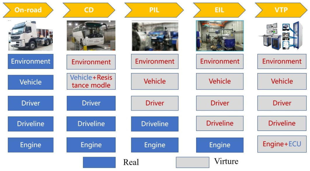
Figure 1. Different development methodologies as the level of virtuality increases.
Atmosphere 17 00717 g001
Figure 2. Configuration of the powertrain-in-the-loop (PIL) test unit, showing the integration of real powertrain hardware with virtual vehicle and environmental models through a real-time simulation platform [16].
Atmosphere 17 00717 g002
Figure 3. Powertrain-in-the-loop (PIL) simulation platform for evaluating powertrain performance, fuel consumption, and emissions under representative transient driving conditions [26].
Atmosphere 17 00717 g003
Figure 4. Hardware layout, simulation and control loop of the powertrain test CIL system for a vehicle model considering tyre slip [28].
Atmosphere 17 00717 g004
Figure 5. PIL test setup for comparing speed-based, torque-based, and enhanced torque-based control strategies under dynamic driving and low-adhesion braking conditions [29].
Atmosphere 17 00717 g005
Figure 6. (a) Schematic of an actual hydraulic hybrid vehicle system and (b) EIL configuration of a hydraulic hybrid vehicle [35].
Atmosphere 17 00717 g006
Figure 7. Closed-loop control principle of the EIL system used for parallel diesel-hybrid powertrain testing [37].
Atmosphere 17 00717 g007
Figure 8. Schematic of the engine test bench used for EIL-based evaluation of a 48 V mild hybrid system [38].
Atmosphere 17 00717 g008
Figure 9. EIL platform for evaluating heavy-duty vehicle emissions and fuel consumption [40].
Atmosphere 17 00717 g009
Figure 10. V-model development and verification process of the RDE+ (R2R-EiL) methodology [56].
Atmosphere 17 00717 g010
Figure 11. HIL-based Virtual Chassis Dynamometer platform for diesel engine virtual calibration [57].
Atmosphere 17 00717 g011
Figure 12. HIL I/O peripheral interface architecture for virtual and physical components [58].
Atmosphere 17 00717 g012
Figure 13. Synergistic application of PIL, EIL, and VTB [68].
Atmosphere 17 00717 g013
Table 1. Comparative characteristics and application scope of PIL, EIL, and VTB methodologies.
TechniqueHardware DependencyApplication StagePowertrain SuitabilityApplicable Cycles/ScenariosModel Accuracy/ValidationCost- and Time-Saving PotentialTypical Tools/EnvironmentRelevant Standards
PILReal powertrain components and powertrain test benchMid-to-late stage; powertrain integration validation and calibrationICE, HEV, PHEV; partially applicable to BEV/FCEV if electric-drive or fuel-cell subsystems are includedWLTC, FTP, CATC, transient calibration cyclesMedium to high; strongly dependent on plant-model fidelity and component boundary conditionsMedium to high; reduces full-vehicle prototype demandAVL FIRE (2025 R2), MATLAB/Simulink (R2026a), dSPACE SCALEXIO (2025-B), GT-SUITE (2026.1)ASAM XIL, model-based validation workflows
EILReal engine, engine test bench and real-time control systemMid stage; engine performance, transient emissions and RDE pre-calibrationMainly ICE, HEV and PHEV; limited direct relevance to BEV; partly relevant to FCEV only if reconfigured for fuel-cell systemsWLTC, FTP, RDE pre-calibration, engine transient cyclesHigh for engine-side control and combustion response; limited for full-vehicle behaviourMedium; reduces repeated vehicle-level emission testsdSPACE (2025-B), LabVIEW (2025 Q3), INCA (V7.6.1), AVL CAMEO (2025 R2), AVL PUMA (2025 R2), ETAS tools (V8.8)ASAM XIL, ECU calibration and test automation standards
VTBECU, actuators, vehicle-level test bench and/or virtual vehicle modelThroughout the V-model; concept design, component validation and vehicle-level consistency verificationICE, HEV, PHEV, BEV and FCEVWLTC, RDE, FTP, CATC, customer-specific drive cyclesMedium to high; suitable for integrated vehicle-level assessment but requires cross-validationHigh; reduces late-stage prototype and road-test demandGT-SUITE (2026.1), AMESim (2504), Simulink, AVL CRUISE (2025 R2), CarMaker (14.0)ASAM XIL, virtual validation and HIL automation frameworks
Disclaimer/Publisher’s Note: The statements, opinions and data contained in all publications are solely those of the individual author(s) and contributor(s) and not of MDPI and/or the editor(s). MDPI and/or the editor(s) disclaim responsibility for any injury to people or property resulting from any ideas, methods, instructions or products referred to in the content.