2.1. Description of the Pin-on-Disc Bench and Particle Measuring Devices
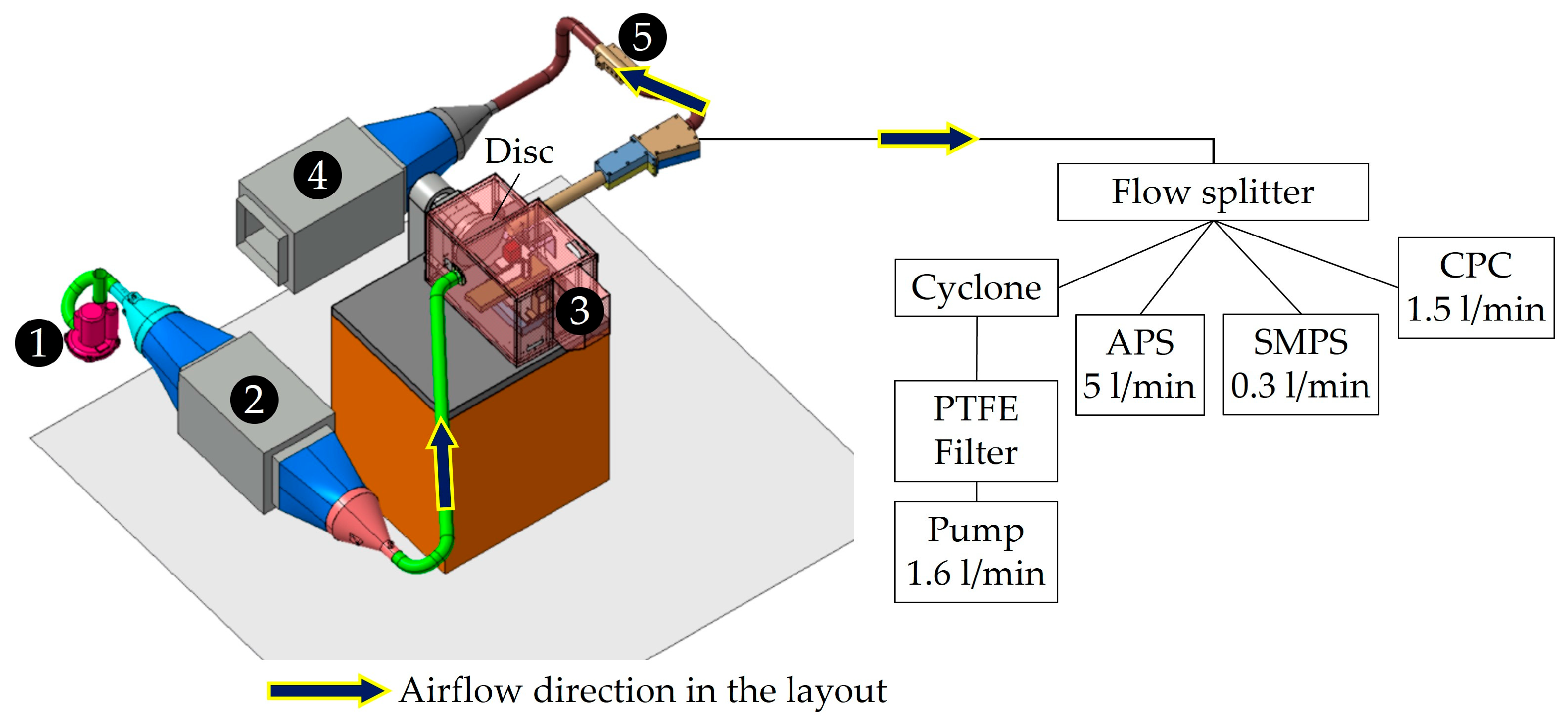
The measurement of braking particles must be controlled. Braking particles must not be mixed up with particles in the ambient air. Additionally, the sampling must be representative of real particle emissions. To achieve this, the mechanical part of the pin-on-disc bench was placed in a sealed enclosure (3).
Figure 1 presents the set-up used in this work [
29,
30,
31,
32]. The enclosure was connected to two filter boxes, (2) and (4), each composed of two filters: one F7 type and one H13 type. This system made it possible to carry out tests with low particle background noise. In addition, the appropriate management of the air flow circulating in the set-up made it possible to carry out particle measurements under isokinetic conditions. The air sent into the set-up was taken by a positive progressive cavity pump (1) controlled by a controller. Furthermore, particle contamination inside the enclosure was prevented thanks to the installation of a positive progressive cavity pump at the inlet of the overall set-up, which created an overpressure throughout the set-up.
The characteristics of the measuring devices used to measure the number, size and mass of particles emitted are presented in
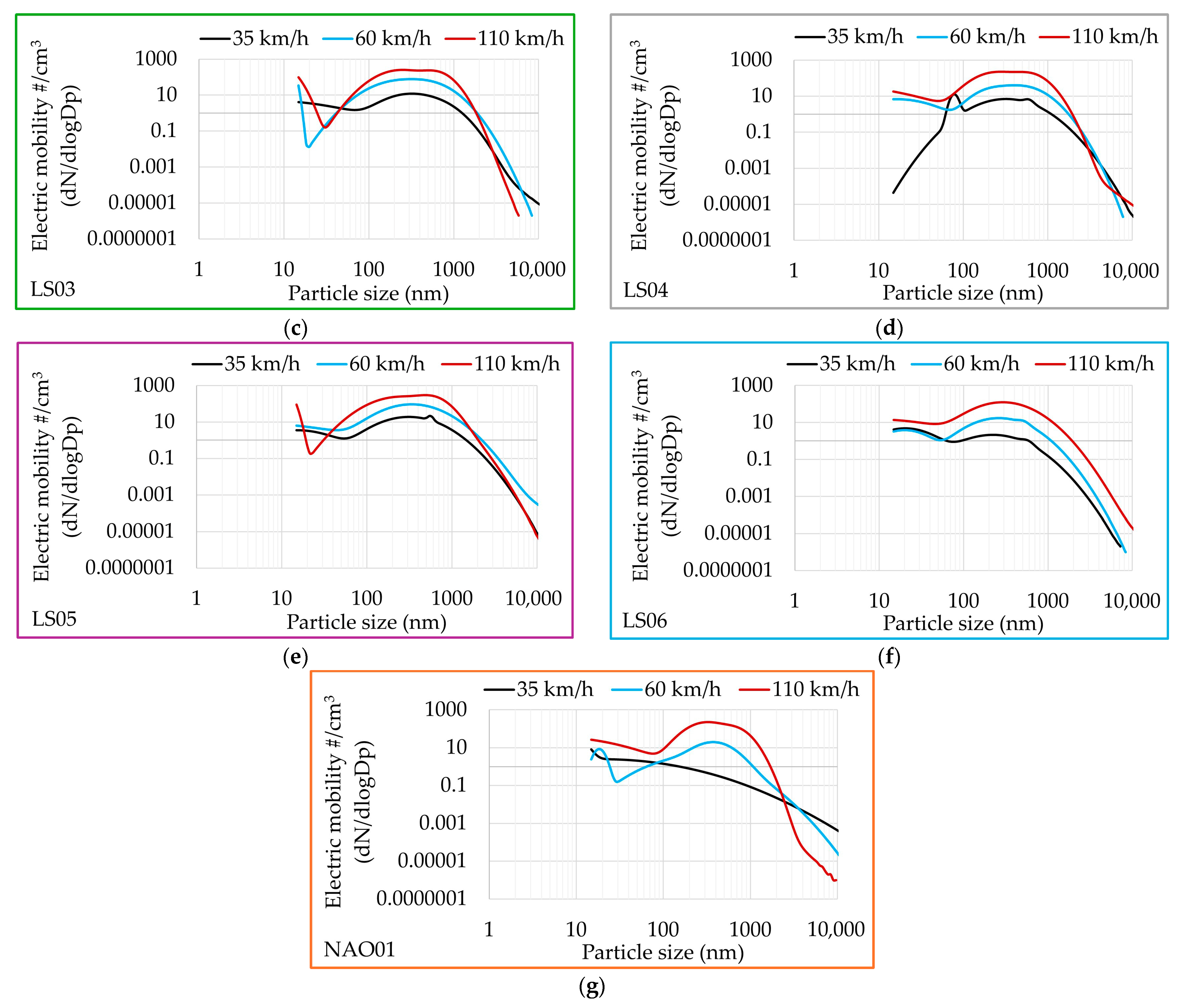
Table 1. One CPC (Condensation Particle Counter) (TSI Inc., Shoreview, MN, USA) was used to count the number of particles. One SMPS (Scanning Mobility Particle Sizer) (TSI Inc., Shoreview, MN, USA) combined with one APS (Aerodynamic Particle Sizer) (TSI Inc., Shoreview, MN, USA) was also used to measure the size of the particles over a wide measuring range, between 14 nm and 20 μm, to accurately characterise brake wear emissions down to a few nanometres. The APS is an interesting metrological solution to measure aerosols because it allows the measurement of aerosols of lower concentrations while maintaining an excellent temporal resolution to process evolving aerosols.
The mass of particles emitted by the seven friction pairs were collected on PTFE filters (FALP03700: 1.0 μm pore size, hydrophobic PTFE, 37 mm diameter) placed in filter holders (cassettes). To sample particles with a size < 10 μm (PM
10), a cyclone (GK 2.69SS (37 mm), Mesa Labs, Lakewood, CO, USA) was placed upstream of the filter holder, and a pump set at a flow rate (
qp) of 1.6 L/min was connected to the filter holder to create a cut at 10 μm. The emission factor (EF
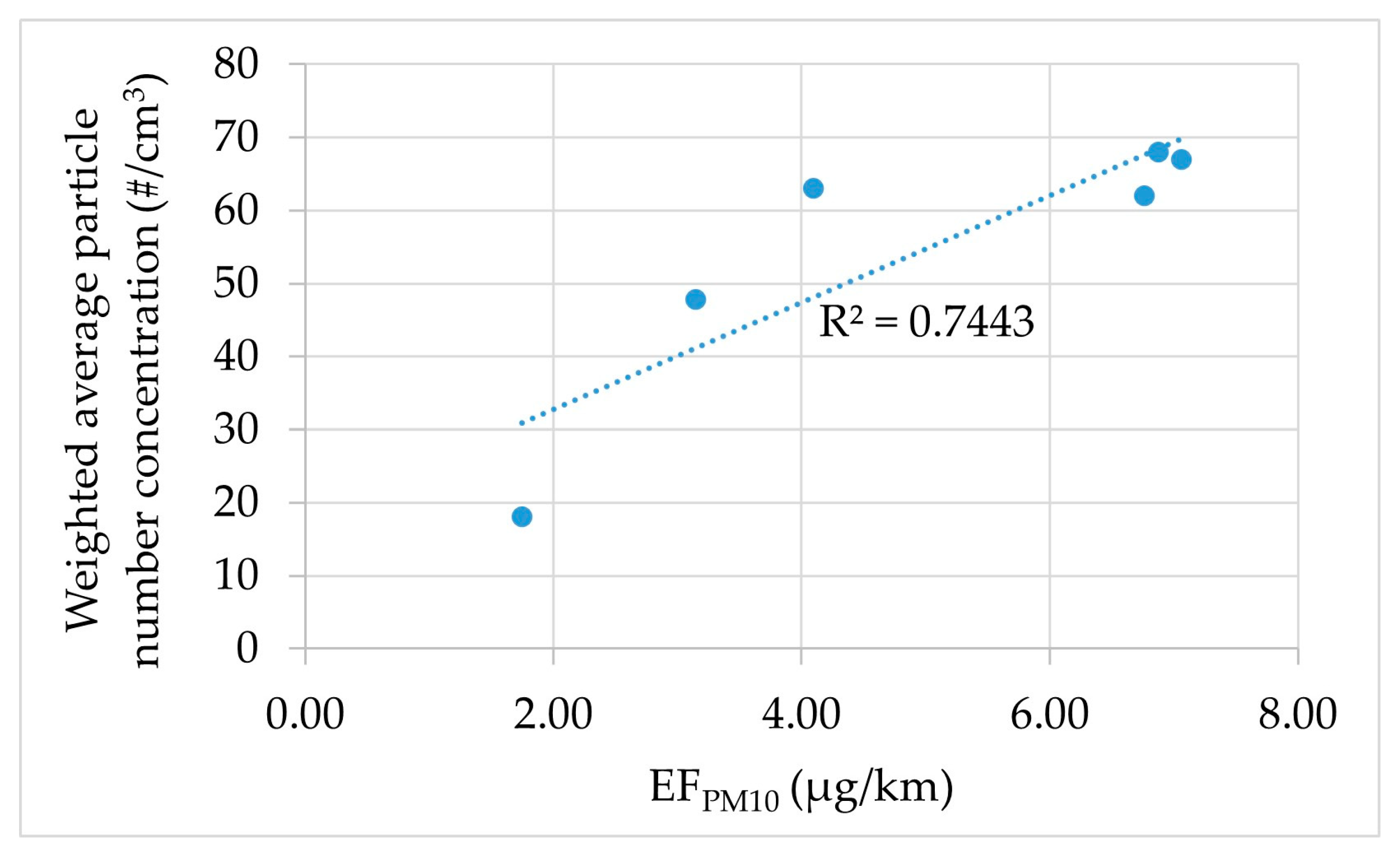
PM10) of each friction pair, expressed in μg/km, was calculated with Equation (1) using the amount of particulate matter emitted per kilometre travelled by the wheel of the car (
d). The mass of particulate matter collected on the PTFE filter, expressed in microgramme, is the difference between the final mass of the PTFE filter (
mff) after the test and the initial mass of the PTFE filter (
mfi) before the test. The ratio of the mass collected on the PTFE filter to the distance travelled was multiplied by the ratio of the average flow rate (
qm), expressed in l/min, measured during the test using the flowmeter ((5) on
Figure 1), to the flow rate of the PTFE filter pump (
qp).
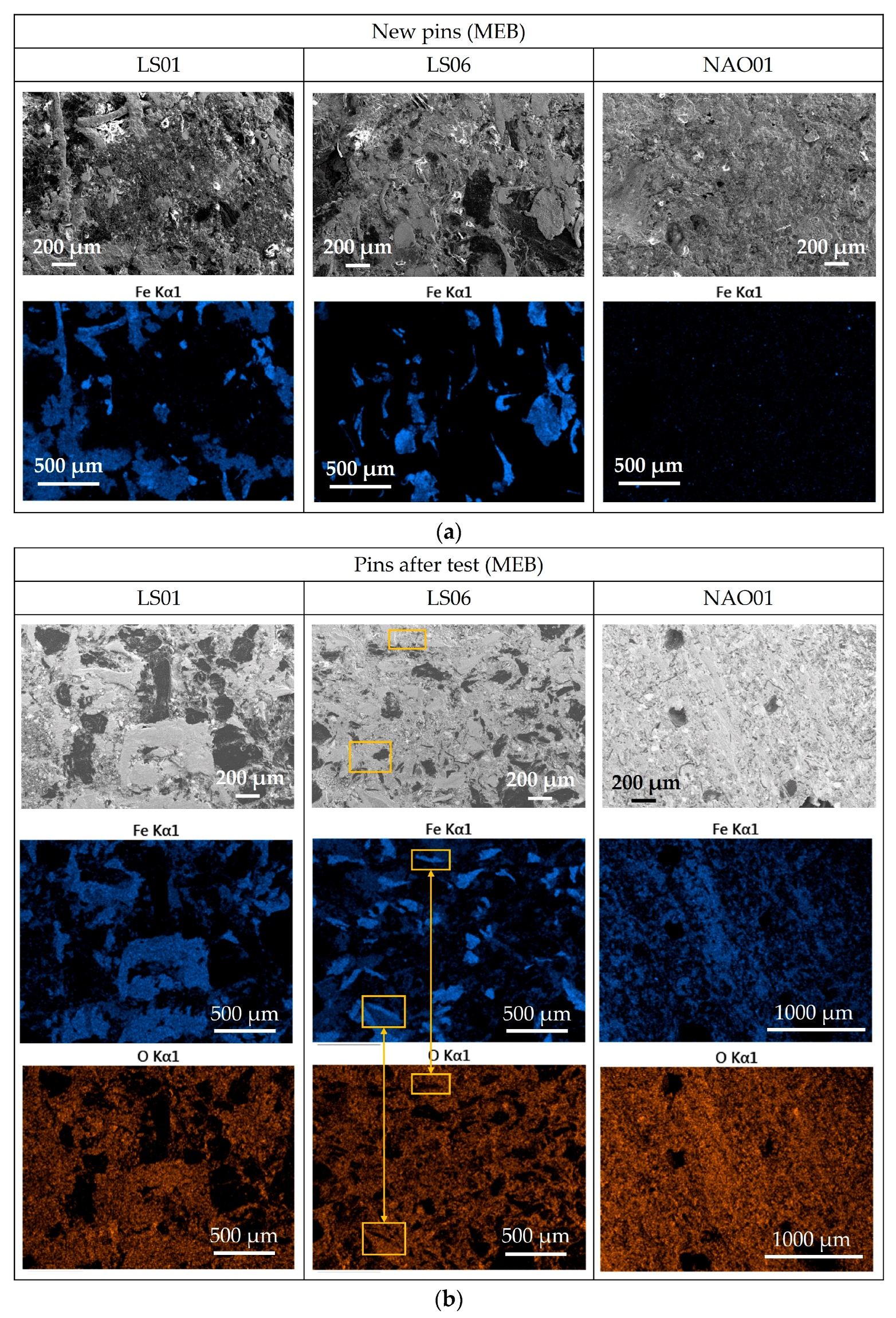
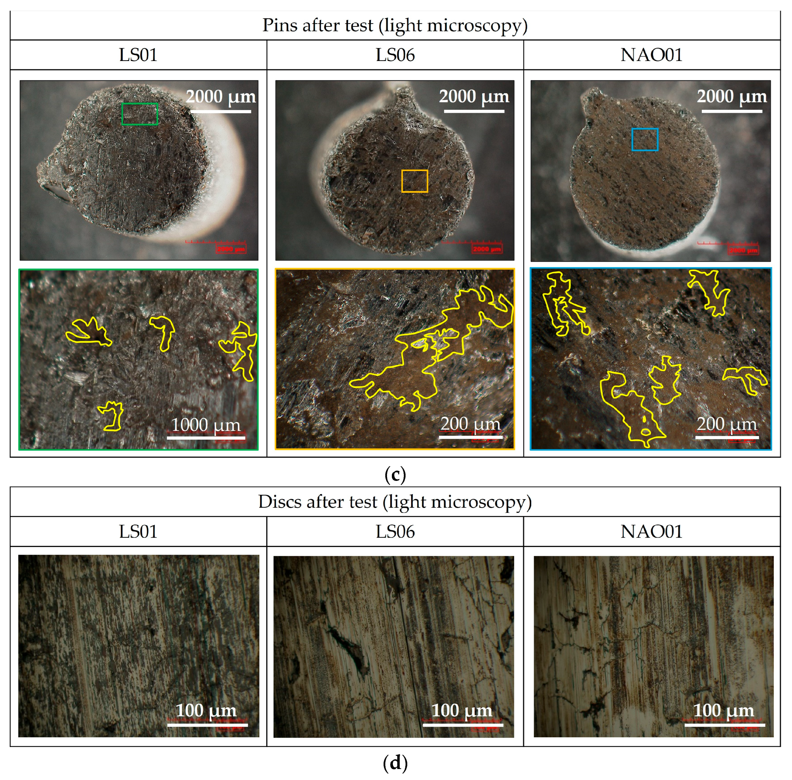
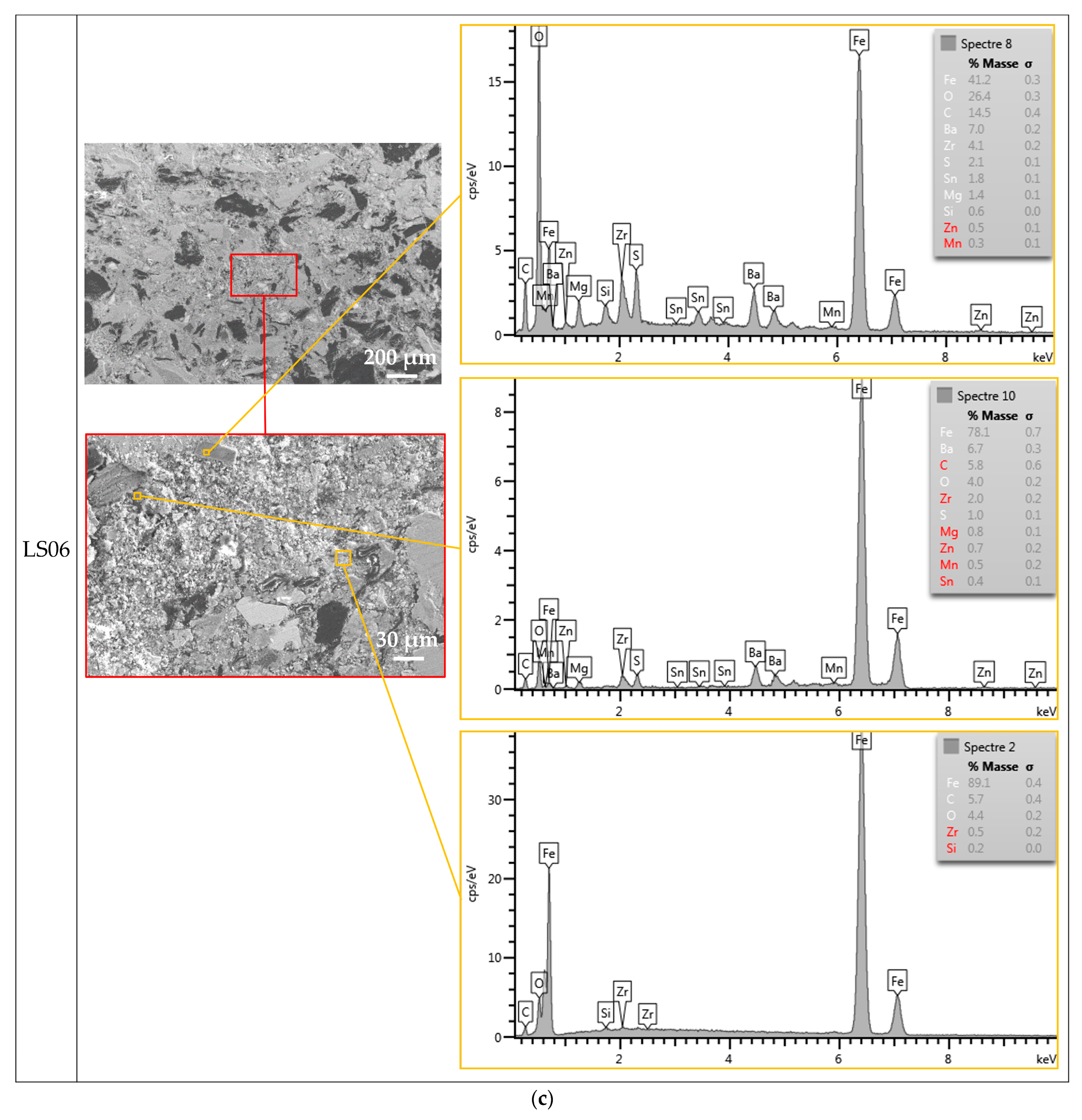
The seven pins were analysed with SEM-EDXS. The scanning electron microscope was a Sigma 300 VP (Zeiss, Oberkochen, Germany), and the energy-dispersive X-ray spectroscopy tool was a X-MaxN (Oxford Instruments, Abingdon, UK). The pins and the brake discs were also observed with a light microscope (KH-8700) (Hirox Europe, Limonest, France).
The PM
10 particles were chemically analysed using both the ICP-MS (Inductively Coupled Plasma-Mass Spectrometry) method and ICP-OES (Inductively Coupled Plasma-Optical Emission Spectrometry) method to quantify chemical elements. In this study, the PTFE filters were nebulized in accordance with the NF-EN-14385 standard [
33]. According to the NF-EN-17294-2 standard [
34], the ICP-MS technique quantifies the chemical elements Ba, Co, Cr, Cu, K, Sn, Zn and Zr, whereas according to the NF-EN-17294-2 standard [
34], the ICP-OES technique quantifies the chemical elements Al, Fe, Mg, Na and Ti.
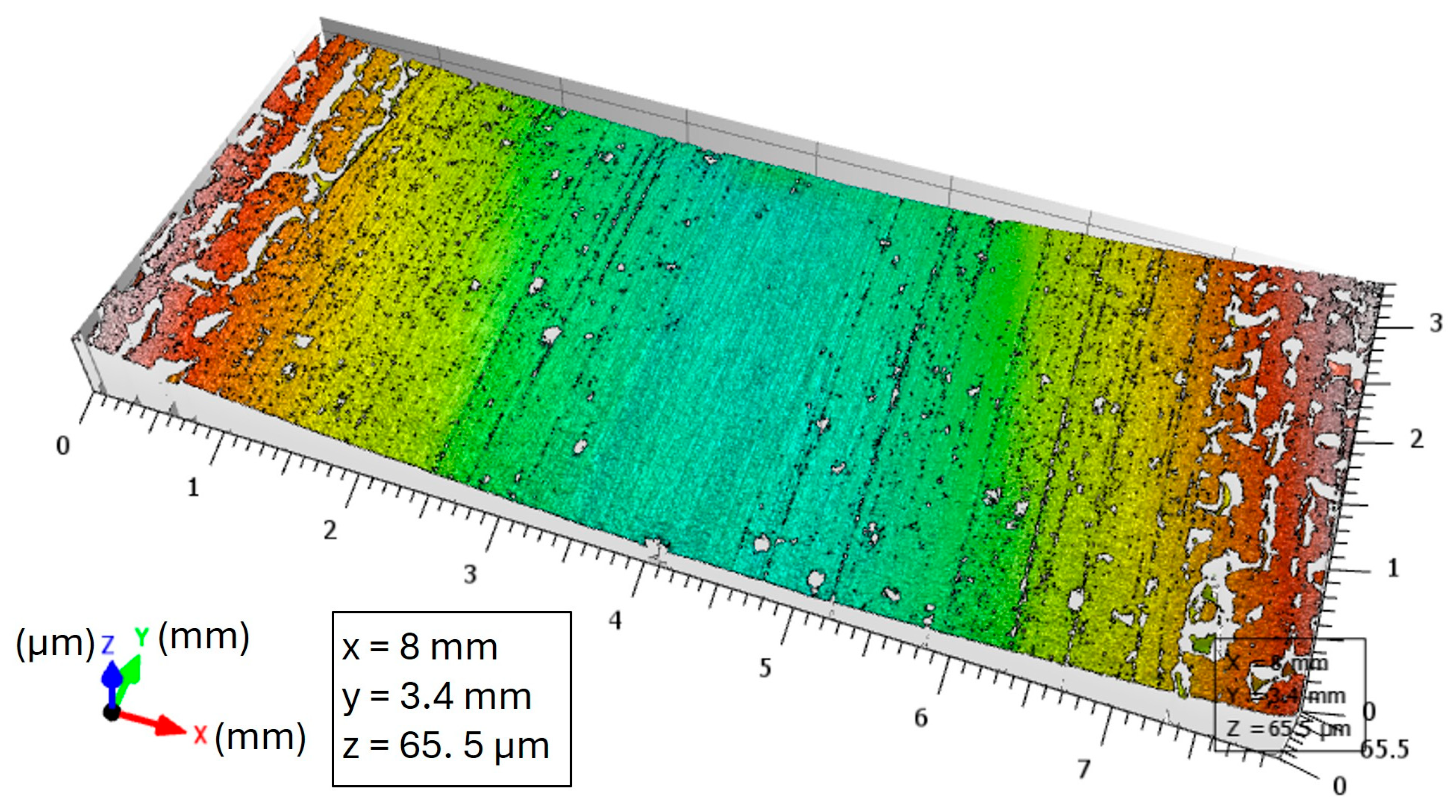
The roughness values (Rp, Rv and Ra) of the seven brake discs was defined according to ISO 25178-1:2016 standard [
35] using an interferometric profilometry (Bruker-Nano Contour GT-K Optical Profilometer) (Brucker, Billerica, MA, USA).
2.2. Friction Materials and Brake Disc
Six Low Steel materials (LS01, LS02, LS03, LS04, LS05 and LS06) and one NAO material (NAO01) were tested as a 5 mm diameter pin. The formulas used for this work are complex unlike some of the friction materials tested in the literature [
21,
23,
26]. The formulas are also copper-free, unlike some which have been investigated elsewhere [
1,
26,
36].
NAO01 material is a common NAO material among copper-free materials. It is a friction material that is asbestos-free, steel fibre-free and copper-free, and it has organic fibres, mineral fibres and a lot of carbon, as well as zirconium dioxide and barium sulphate. The six copper-free Low Steel materials have compositional differences. LS01 and LS02 are the closest in terms of composition, but LS02 has more abrasives (20% by volume in total). This modification of the LS02 material aims to increase the ‘cold’ friction coefficient (at low brake disc temperature) and usually causes more wear of the cast iron brake disc. LS03 material has fewer abrasives and a higher synthetic fibre content than LS01 and LS02. A study showed interesting behaviour for the reduction in particle emissions using organic fibres [
25].
LS04, LS05 and LS06 friction materials have been formulated from the LS01 friction material formula with the aim of reducing brake particle emissions. LS05 is close to LS01, but aluminium oxide has been replaced by magnesium oxide, and both have another common abrasive. A study performed using different oxides as abrasives showed interesting behaviour for the reduction in particle emissions using magnesium oxide [
24]. LS04 and LS06 have approximately 50% less steel fibres by volume (
Table 2) and 50% more barium sulphate by volume than other Low Steel materials. Increasing the barium sulphate content was chosen because interesting behaviour for the reduction in emissions using this raw material has been observed [
1,
36,
37]. LS06 is also the only Low Steel composed of an abrasive usually used for NAO material: zirconium dioxide.
Table 2 gives the chemical composition of the seven friction materials and the brake disc, as well as the steel fibre content of the friction materials. In this table, the weight percentage of iron found in LS01 (24.961 wt.%) is higher than the weight percentage of iron found in LS02 (17.396 wt.%), whereas they have the same content of steel fibre in volume percentage (16.50 vol.%) and nearly the same content of steel fibre by considering the weight percentage (37.64 wt.% for LS01 and 36.13 wt.% for LS02). The difference in steel fibre content in weight percentage in LS01 and LS02 is due to the difference in density of the friction material (LS01 has a lower density than LS02). The difference in iron content in weight percentage found in the XRF results is due to the fact that the friction materials are composed of other materials containing iron and because they have different densities.
An EDX-7000 model (SHIMADZU France, Noisiel, France) was used to determine the elemental composition by X-ray fluorescence (XRF) of the friction materials presented in
Table 2.
The cast iron brake disc is a commercial disc with a size of 266 × 22 (disc diameter in mm; disc thickness in mm). The EMIA 920-V2 (Horiba, Palaiseau, France) was used to define by infrared detection the contents of carbon and sulphur of a brake disc. The contents of the other elements were defined by ICP-OES (Spectro ARCOS) (SPECTRO Analytical Instruments GmbH, Kleve, Germany).
2.3. Test Conditions
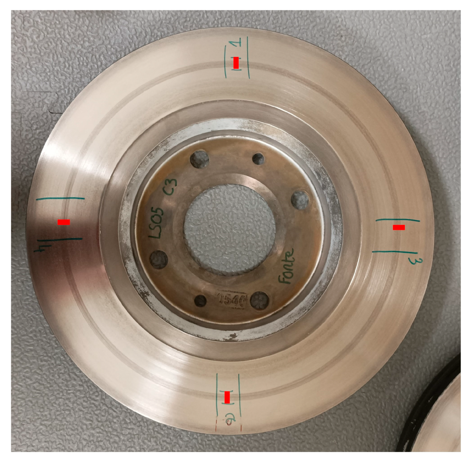
All friction materials were tested against a cast iron disc in new condition. The seven brake discs were prepared in the same way. The anti-corrosion layer of the discs, consisting of a coating mainly made of zinc and aluminium particles, was removed to prevent possible contamination of the air with zinc and aluminium particles. For this purpose, all brake discs were completely immersed in a bath of white vinegar (18 degrees acetic acid) for ten minutes. Then, the residues of the anti-corrosion layer were removed with a grade P#1000 sandpaper (grit 1000 μm). The discs were then washed with demineralised water and dried to prevent the formation of rust on the discs’ surfaces. Afterwards, the brake discs were manually bedded with P#120 grade sandpaper (grit 120 μm) for seven minutes at a disc rotational speed of 800 rpm. The purpose of this operation is to reduce the roughness of the discs to reduce the bedding time of the 5 mm diameter pins. The pin axle is located 109 mm from the disc axle.
Next on the pin-on-disc bench, the friction pairs were bedded for approximately an hour during the ‘bedding cycle’ before collecting the PM
10 on the PTFE filters during the ‘emission cycle’ for another hour (
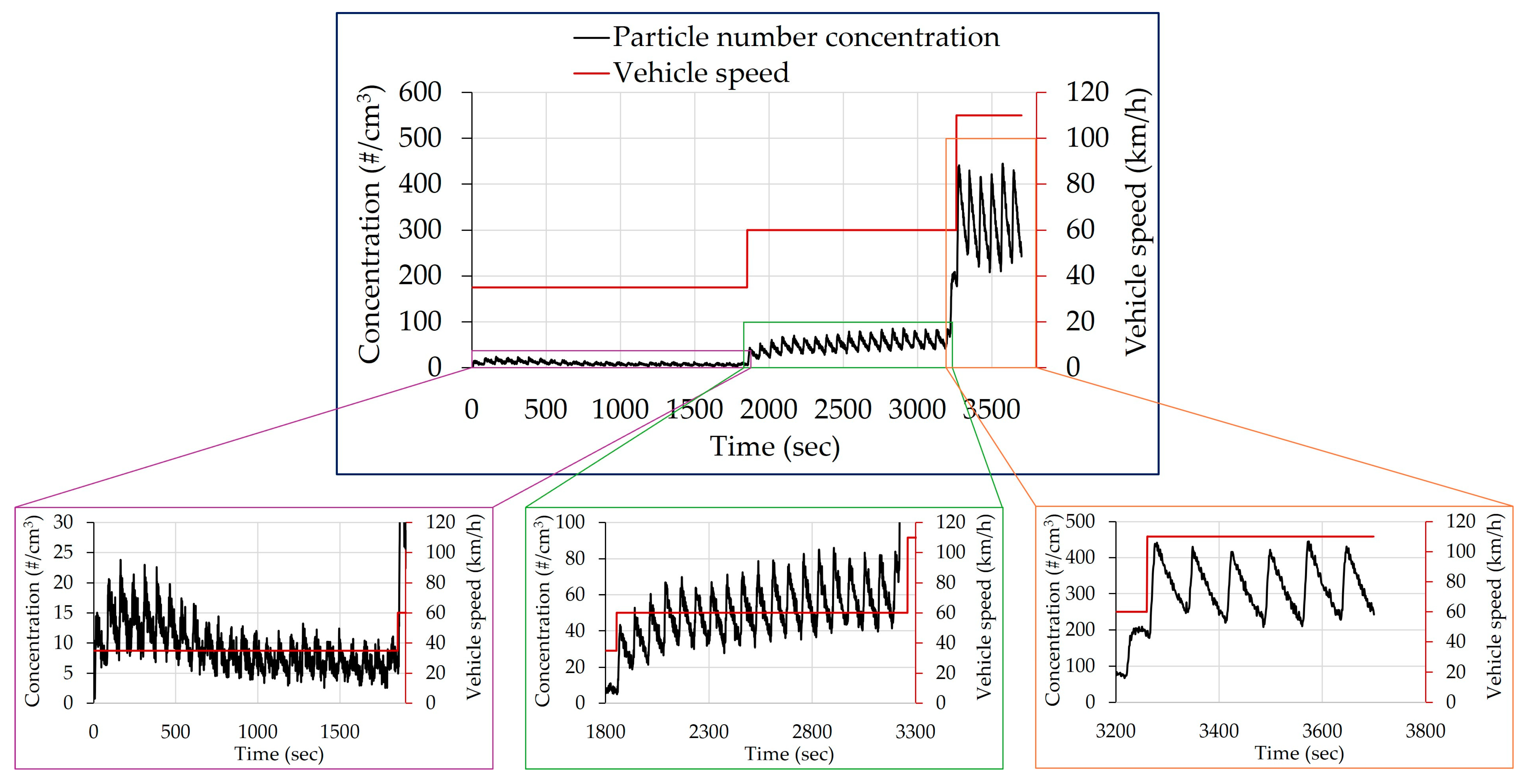
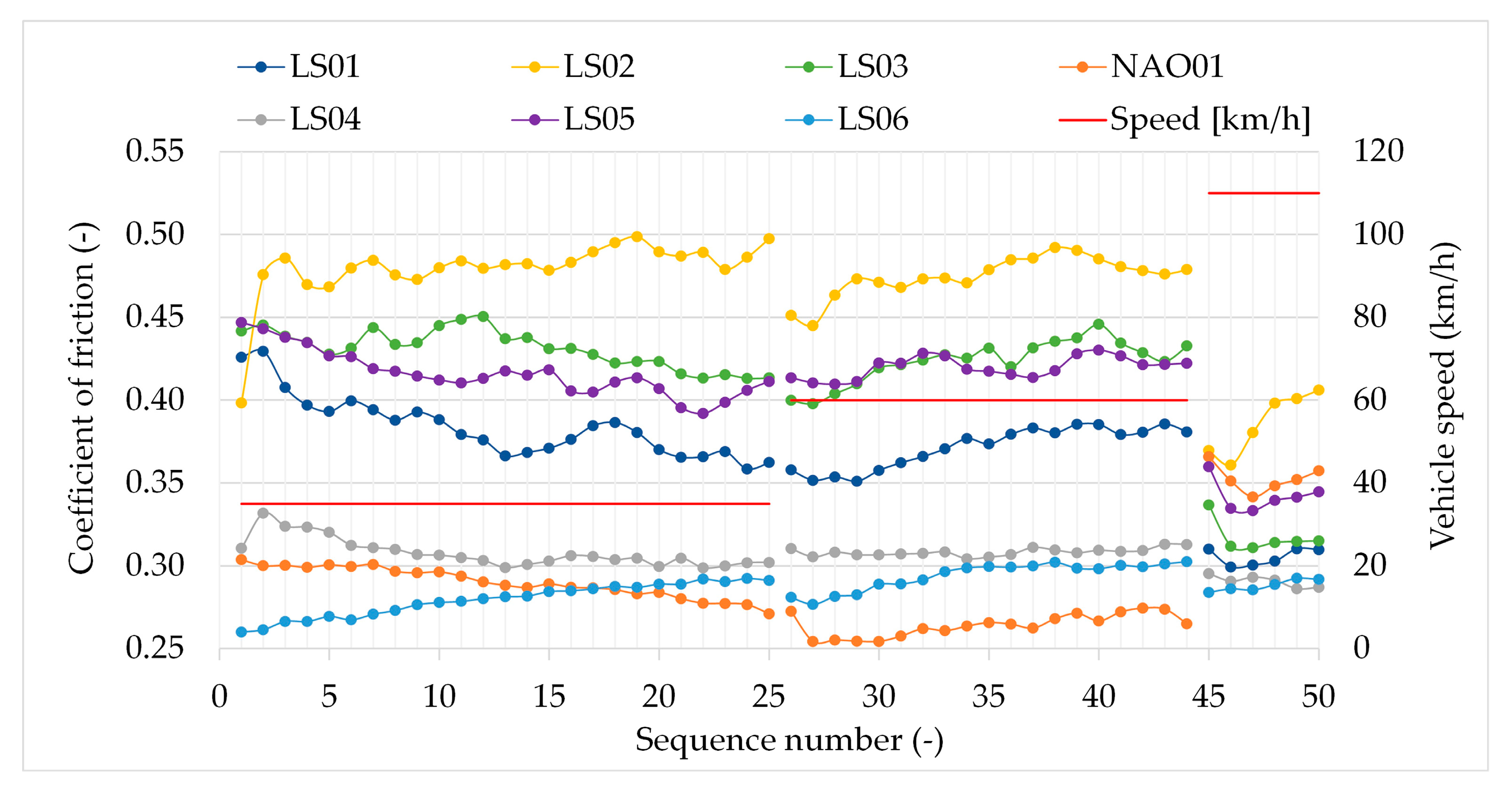
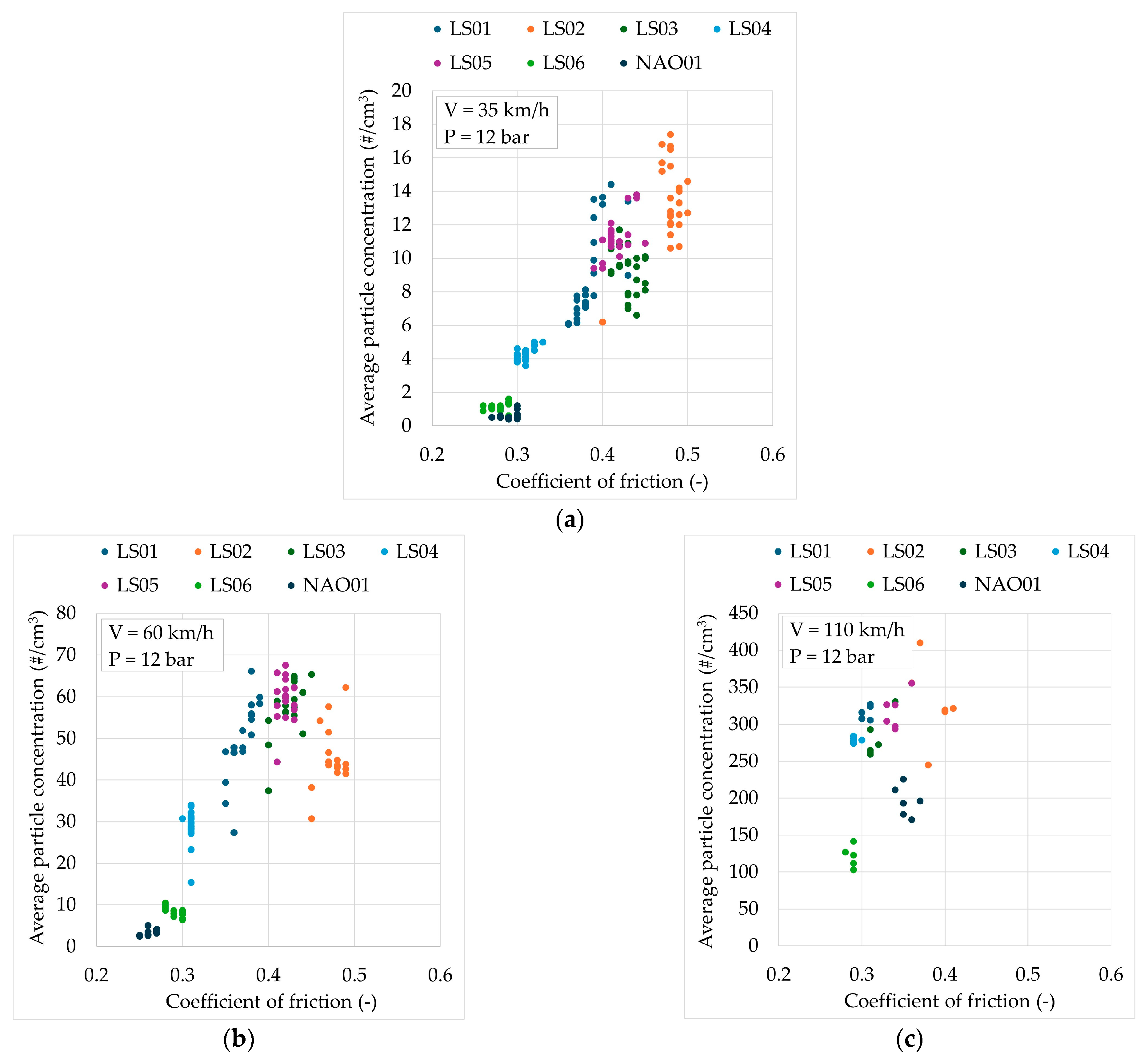
Table 3). The emission cycle is composed of 50 loading sequences, and the three vehicle speeds (in km/h) used to create the ‘emission cycle’ were chosen using the standardised WLTP cycle (Worldwide Harmonised Light Vehicles Test Procedure). The protocol used to select the three test speeds is the following:
The values of the initial speeds of the 114 braking of the WLTP-Trip#10 were sorted by ascending order. WLTP-Trip#10 was chosen because it is the most energetic part of the whole WLTP cycle.
Speeds corresponding to 50%, 80% and 98% of cumulative brakings were chosen. These speeds correspond to initial speeds of 35 km/h, 50 km/h and 102 km/h.
Then, these three values were adapted to obtain rather different range of values which are representative to the real driving conditions. The speed of 35 km/h was kept because this value represents a good condition of urban driving in the city centres. So, 50% of the loading sequences of our ‘emission cycle’ were performed at a speed of 35 km/h, corresponding to 25 loadings. Then, instead of 50 km/h, a speed of 60 km/h was chosen because this value represents a good condition of driving on the outskirts of the city (between 50 km/h and 70 km/h generally). In the WLTP-Trip#10 cycle, 38% of the brakings are performed at an initial speed between 35 km/h and 60 km/h, corresponding to 19 loading sequences in our ‘emission cycle’. Finally, a speed of 110 km/h was chosen because this value represents a good condition of driving on expressways such as ring roads and motorways. In the WLTP-Trip#10 cycle, 12% of the brakings are performed at an initial speed higher than 60 km/h, corresponding to 6 loading sequences in our ‘emission cycle’.
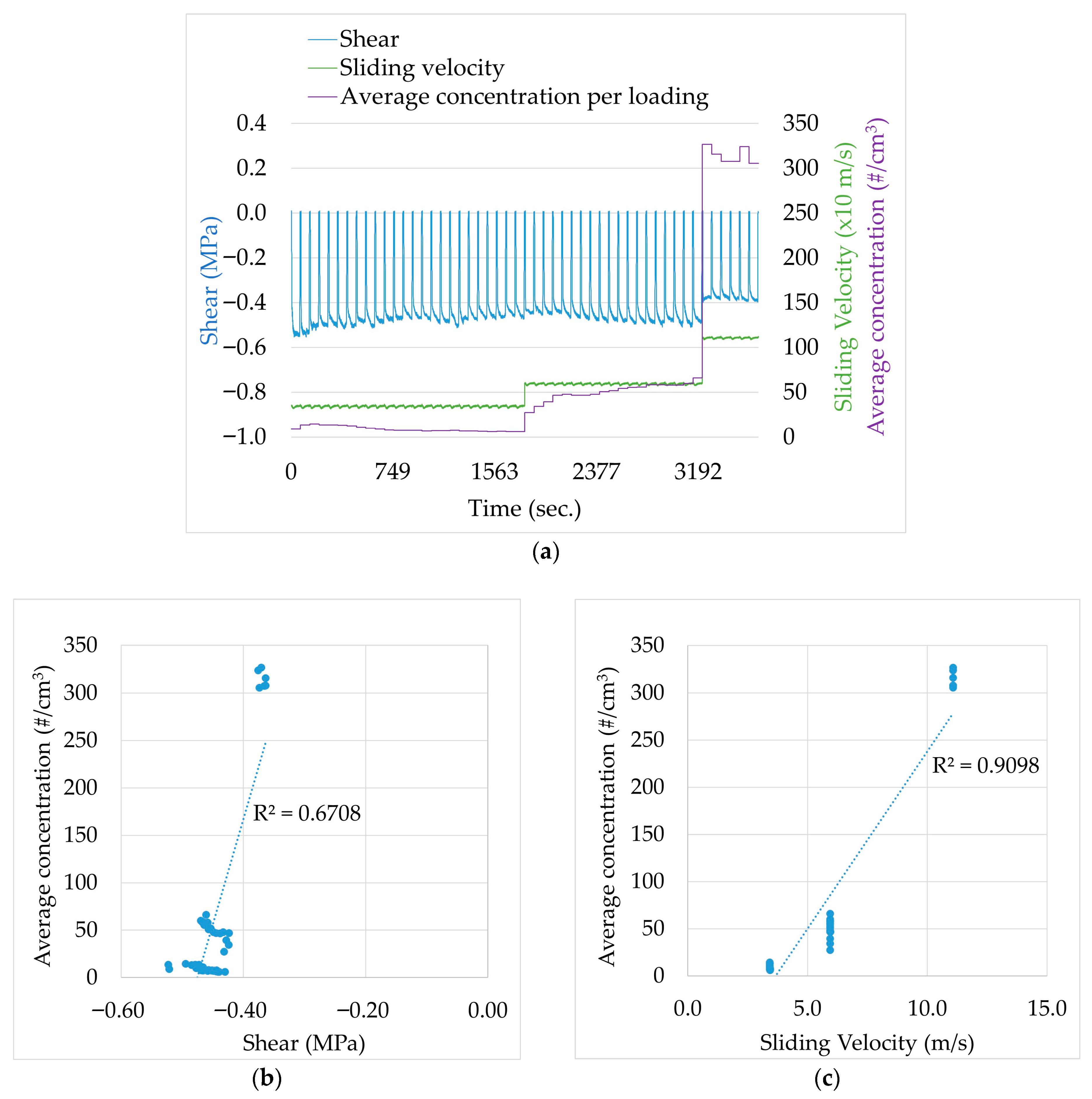
The sliding velocities presented in
Table 3 are equivalent to vehicle speeds of 80 km/h, 35 km/h, 60 km/h and 110 km/h by using the vehicle parameters presented in
Table 4. The disc rotational speed does not vary with friction. The contact pressure applied was constant during the test and equals 1.2 MPa, which is equivalent to 23.6 hydraulic bar on the vehicle.
In terms of braking energy, considering the dissipated energy (in J) divided by the (dissipating) surface of two pads (9020 mm2), the total surface-specific dissipated energy during the WLTP cycle is around 1089 J/mm2 for our reference brake.
