1. Introduction
Rossby waves [
1] are a type of large-scale nonlinear wave generated by the Earth’s rotational effects, with propagation driven by the latitudinal changes in the Coriolis force. These waves are crucial in atmospheric and oceanic dynamics, particularly in the study of large-scale circulation and climate variability [
2,
3]. A unique characteristic of Rossby solitary waves is their stability, which is strongly affected by topography and background flow conditions. As early as 1964, Long [
4] derived that under the
-plane approximation, the amplitude evolution of Rossby waves satisfies the Korteweg–de Vries (KdV) equation. In 1966, Benney [
5] extended Long’s conclusion and additionally found that the speed of Rossby solitary waves is related to wave amplitude. Furthermore, Larsen [
6] and Clarker [
7] also studied the evolution of Rossby solitary wave amplitude, arriving at results similar to those of Long. The propagation of Rossby waves is influenced by topography, latitude variations, and atmospheric or oceanic density distribution, with their dynamics being particularly prominent in mid-to-high-latitude regions. As the primary form of meso- and planetary-scale disturbances in the atmosphere and oceans, Rossby waves play a key regulatory role in the variability of climate phenomena such as the tropospheric polar vortex and monsoon systems. It should be clarified that the tropospheric polar vortex initially forms due to polar cold sources and the Coriolis force, while Rossby waves do not directly drive its formation—instead, they modify the vortex’s circulation intensity or induce its eccentricity through energy transport, consistent with the findings of Woollings [
8]. Moreover, the slow propagation and long-periodic nature of Rossby waves allow them to affect atmospheric variability over extensive time and spatial scales [
2,
9].
Nonlinear dynamics have become a focal point in the study of Rossby waves. Research by Zhang [
10] used the derivative expansion approach to investigate the dynamics of Rossby wave packets with topographic features, showing that topography has a profound impact on wave packet evolution. Yang et al. [
11,
12] introduced various nonlinear equations, including the Zakharov–Kuznetsov–Boussinesq–Ono (ZKBO) equation, to characterize Rossby solitary waves in three dimensions. The effects of topography, heating, and basic flow on these waves have been extensively investigated, significantly influencing wave propagation characteristics [
13,
14,
15,
16]. For instance, Yang et al. [
17,
18,
19,
20] explored how local topography can lead to baroclinic instability, while Vanneste [
21] examined the finite damping of Rossby waves due to topographic influences. Han et al. [
22] further studied the dynamics of Rossby algebraic solitary waves induced by large-scale topography, confirming that large-scale topographic features significantly modify the amplitude and propagation modes of these waves.
Zhang et al. [
23] also employed the Ostrovsky hierarchy method to model the dynamics of nonlinear Rossby solitary waves, discovering that these waves exhibit similar stability characteristics. Additionally, Hou et al. [
24] investigated the quartic
hierarchy of nonlinear Rossby waves and its dynamics, revealing the influence of topography on the nonlinear propagation of these waves. Wang et al. [
25,
26] studied solitary waves of nonlinear barotropic–baroclinic coherent structures and analyzed the impact of nonlinear interactions in the atmosphere and oceans.
The propagation of Rossby waves is inherently linked to environmental factors such as temperature gradients and atmospheric density distribution, which alter their dynamics [
27,
28]. Studies in recent decades, along with recent advances, have revealed the significance of algebraic solitary waves, which maintain stability and exhibit slow amplitude decay during propagation, making them particularly relevant in complex atmospheric and oceanic systems [
29]. Zhang et al. [
30] investigate the coherent structures resulting from nonlinear barotropic–baroclinic interactions in an unequal depth two-layer model. With the increasing effects of global warming and human activities, understanding the evolution of Rossby solitary waves has become critical for climate and weather predictions [
31]. Recent advancements in numerical methods, such as the shooting method and Fourier spectral method, have facilitated the analysis of these waves under varying conditions [
32]. Furthermore, studies have shown that the interaction between Rossby waves and other atmospheric phenomena, such as polar vortex dynamics, can have significant implications for weather variability.
Notably, Rossby algebraic solitary waves represent a special type of nonlinear solitary wave, characterized by slow amplitude decay and stable propagation. For algebraic solitary waves, the amplitude generally decays gradually with propagation distance, allowing for stable waveform maintenance over long distances and timescales. This stability enables Rossby algebraic solitary waves to persist even in complex environments, where they demonstrate certain propagation advantages in atmospheric and oceanic systems [
33,
34]. Studies have shown that these solitary waves can exhibit significant nonlinear responses when interacting with topography and temperature gradients and can adjust their propagation direction and amplitude in response to external disturbances [
35,
36,
37]. These properties indicate that Rossby algebraic solitary waves not only hold substantial theoretical value in atmospheric and oceanic dynamics but may also play a critical role in practical climate forecasting [
8,
38].
To investigate the evolutionary characteristics of Rossby algebraic solitary waves, this paper starts from the shallow-water equations [
39,
40,
41]. The shallow-water equations are a set of fundamental equations that describe fluid movement under shallow-water conditions, applicable to atmospheric and oceanic fluid dynamics. Within the perturbation framework, the shallow-water equations can be simplified to reflect the nonlinear and dispersive characteristics of waves. Through perturbation expansion, we can derive the amplitude evolution equation from the shallow-water equations, leading to the BDO equation [
42,
43]. A recent study by Flamarion and Pelinovsky [
44] has refined the nonlinear term coefficient in the BDO equation for weakly stratified fluids, establishing a quantitative relationship between topographic amplitude, spatial wavenumber, and the dispersion parameters of the equation. This work provides a direct theoretical foundation for incorporating the topographic function
into the coefficient calibration of the BDO model in our study. The third part utilizes the PINNs method [
45] to solve this equation and conduct an analysis. PINN is a novel approach that directly incorporates physical laws into the neural network training process, enabling the efficient solution of complex partial differential equations. For two-component BDO systems, Zhao and Qu [
46] developed a perturbative symmetry-based discrete framework to mitigate numerical dispersion in Hilbert transform computations, though its computational efficiency diminishes when applied to scenarios with variable topographic parameters. Unlike traditional numerical methods, PINN does not rely on grid discretization but optimize the neural network parameters such that the network output satisfies the initial and boundary conditions, as well as naturally adheres to the physical constraints of the partial differential equations. This method has been proven effective in solving complex wave dynamics problems, such as the KdV equation and the NLS equation. By leveraging the physical constraints in the BDO equation, this method provides accurate solutions and deeper insights into Rossby wave dynamics. Finally, the study examines the effect of topography on the evolution of Rossby wave amplitudes.
2. Model and Hypotheses
The shallow-water equations [
39] for a uniformly rotating fluid over variable bottom topography can be represented in the following form:
where
,
,
,
,
,
and
stand for the eastward velocities, northward velocities, surface elevation, undisturbed water depth, time, eastward coordinate, and northward coordinate, respectively. In this work, all physical quantities with a superscript “∗” denote dimensional quantities. Also, mark the lower part with asterisks as dimensional variables.
,
g are defined as the Coriolis parameter and gravitational acceleration, respectively. The
parameter represents the latitudinal gradient of the Coriolis parameter, and
is defined as relative vorticity. The expression
is for conservation of potential vorticity, where
stands for the derivative of matter along the path of the particle. Because of the continuity equation, we can set up the following stream function
,
By substituting Equation (
4) into Equation (
2) we get the relative vorticity
where
is the gradient operator and
stands for the Laplace operator. The first and second terms of Equation (
5) are the vertical water column vorticity and topographic vorticity, respectively. This is the result of the advection function interacting with the gradient of the bottom topography. This factor is highly relevant when both the slope of the bed and the volume of material transported are large and nearly the same, which is often seen on continental slopes.
Substitute Equation (
5) into Equation (
3) to get
where
is the Jacobian operator. The first term in Equation (
6) represents the dynamic vorticity rate of change for the barotropic stream function, indicating the effect of the vertically integrated rotation of the water column. The second term represents the temporal rate of change in topographic vorticity. In the third term, we observe the deviation of the flow relative to the line of
. The fourth term denotes the nonlinear interaction or advection of the dynamic vorticity. The fifth term represents the variation in planetary vorticity. The sixth term captures the advection effect in topographic vorticity. The seventh term describes the advection of topographic vorticity across an inclined bottom. The eighth term denotes the advection of dynamic vorticity along an inclined bottom.
We designate Equation (
6) as the topographic potential vorticity equation. Following this, we perform the nondimensionalization of Equation (
6) using the characteristic scales of horizontal length
L, characteristic time scale
T, characteristic horizontal velocity scale
U, and characteristic vertical depth scale
. Setting the depth as
, we let
represent the nondimensional bottom topography. Additionally, the small nondimensional number is assigned to
and the mass transport function takes the nondimensional form of
. As a result, we arrive at the following nondimensional form
Because the geomorphological concept underpins the scaling factor
, (
), we obtain the nondimensional form of the governing equations with the topography
The basic stream function is taken as the zonal flow
where
denotes the wave speed. Next, the topography will be established as
where
is the small parameter used to measure the extent of nonlinearity. Thus, the total stream function is given by
By neglecting the prime on the perturbation stream function
without loss of confusion, and substituting Equations (
10) and (
11) into (
8), we obtain the following equation:
where
, and
represents the dimensionless bottom topography profile function, while the symbol
with a dot denotes the first-order partial derivative of
with respect to its argument
y. Equation (
12) describes the dynamics in the region
, based on
’s boundary conditions, which allow us to neglect the topography in the external region and derive the relevant equations for the case where the Coriolis force
:
In Equation (
12), the variables
x,
y, and
t undergo the Gardner–Morikawa transformation
By substituting Equation (
15) into Equation (
12), we get
In Equation (
16),
. Expand
in terms of the small parameter
Equation (
17) is substituted into Equation (
16) to obtain the equations of the reduced perturbation problems of each other. The equation in the zeroth order of the small value of
is
:
where
. Assuming that
, as
, then the following form holds:
Substitute (
19) into Equation (
18) to get
In order to understand how wave amplitude evolves with time, we continue to solve and derive the first-order equation, which is
:
The non-singular solution condition is required to be
The left hand of Equation (
20) is determined by the external (
13), (
14). Since the external disturbance is generated through the inside, we have
Substituting (
23), (
24) into (
13), (
14) gives the lowest-order external equation
where
. According to Ono [
47,
48], it is easy to obtain (
25), (
26)
The soulution of (
27) is
where
represents the above integral principal value. Upon differentiating with respect to
y, we find
The inner solution in the
y direction is smooth at
L,
, and therefore at
, it has
and
As given by (
19) and (
30),
Plugging (
30) into (
29) leads to
where
represents the Hilbert transform of
. Using (
31) and (
33), we can obtain
and
Substituting (
32), (
34), and (
35) into (
22) leads to
To accurately characterize the topographic modulation effect on Rossby waves, the flow field is partitioned into inner and outer regions based on the Ono boundary conditions, with their respective dynamical characteristics specified as follows:
Inner Region: Spatially defined as the zone of significant topographic influence, , where L represents the characteristic topographic scale (set here as m, consistent with the half-width of mid-latitude mountain systems). The core dynamical process in this region is the topography–vorticity interaction: the topographic vorticity term modulates the evolution of relative vorticity, thereby influencing the nonlinear growth and decay of Rossby wave amplitude.
Outer Region: Defined as the zone where topographic effects are negligible,
or
. Here, the topographic height
, and the dominant dynamics reduce to dispersion-driven propagation in the absence of topography. The flow evolution is governed solely by the Coriolis force and background flow, leading to a linear wave equation free of topographic terms. The solution in this region is expressed in terms of a principal value integral (Equation (
28)). The outer solution must satisfy matching conditions at the boundaries
with the inner solution—specifically, the continuity of the stream function and its normal derivative—thereby providing rigorous boundary constraints for the amplitude evolution in the inner region.
Equation (
36) is known as the
equation. As indicated by the parameters, the coefficients of the equation depend on
,
, and the terrain
. The parameters associated with terrain variations modify the linear terms, thus influencing the dispersive properties of Rossby solitary waves, and the parameters
,
D,
S,
Q,
F,
M,
V,
G,
E, and
Z are specified in
Appendix A. In the limiting case of vanishing topographic influence (
), Equation (
36) reduces to the classical
equation [
47] as all topographic coupling terms (specifically coefficients
F,
M, and
G containing
) become negligible. Under the condition of suppressed dispersive effects (
), the equation simplifies to a
-type [
4] formulation with topographic modulation, aligning with the topographic Rossby wave structure previously established by Long. The derivation assumes shallow-water conditions (
);
-plane framework (
); and weak nonlinearity (
). The convergence of the perturbation expansion is ensured by
, while all dimensional parameters are constrained by observational data from mid- and high-latitude atmospheric regimes.
3. Results and Discussion
Next, we set
to be
where
B and
are set as constants,
B represents the topographic amplitude, and
is the angular velocity of the wave, respectively. Then we have
,
, and
And for that, we get
Substituting (
38) and (
39) into Equation (
20) yields
A PINN is a numerical method. The core idea of a PINN is to incorporate the physical constraints of the PDE into the loss function, thereby training the neural network. The basic procedures for solving differential equations with the PINN method are as follows:
First of all, a neural network has to be constructed as a surrogate model for the solution of the differential equation.
The training set of the neural network needs to be specified (typically including two sets for the spatiotemporal domain and boundary conditions).
The loss function needs to be defined by means of the weighted sum of the norms of the residuals of the equation and the boundary conditions.
Minimize the loss function L to train the neural network and acquire the optimal values of the parameters.
In the process of solving the equation, the time domain is defined as
and the spatial domain is
. We build a neural network that consists of three hidden layers, with 100 neurons in each layer. The
function is chosen as the activation function for the neural network, and the weights of all layers of the neural network are initialized via the Xavier initialization approach. When it comes to the training process, we randomly sample 3000 training-data coordinates inside the equation by using the Latin hypercube sampling technique. Meanwhile, 200 training-data coordinates are sampled from both the initial conditions and the boundary conditions. Subsequently, the Adam algorithm is utilized to perform 40,000 iterations on the neural network. Finally, the trained neural network is utilized to compute the predicted values of the equation’s solution at the given coordinates. These predicted values are then compared with the analytical solutions of the equation. Next, Equation (
40) will be solved using the PINN method.
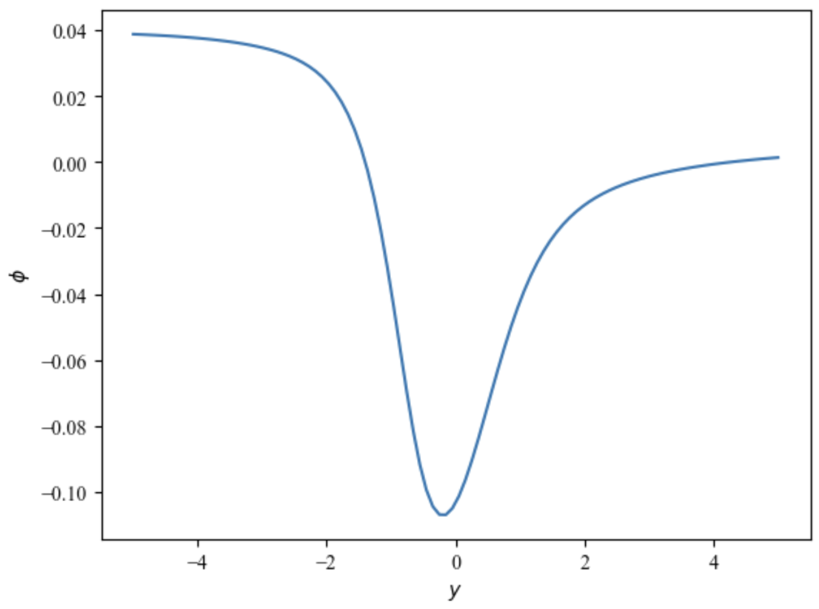
Substitute the obtained
(as shown in
Figure 1) and Equations (
37)–(
39) into the respective parameters in
Appendix A to obtain the parameters
,
D,
S,
Q,
F,
M,
V,
G,
E, and
Z, where
.
Substitute the given parameters and let
into the soulution of the amplitude
A in Equation (
36), where
is the initial amplitude and is set to
.
The solution to Equation (
36) is also obtained using the PINN method.
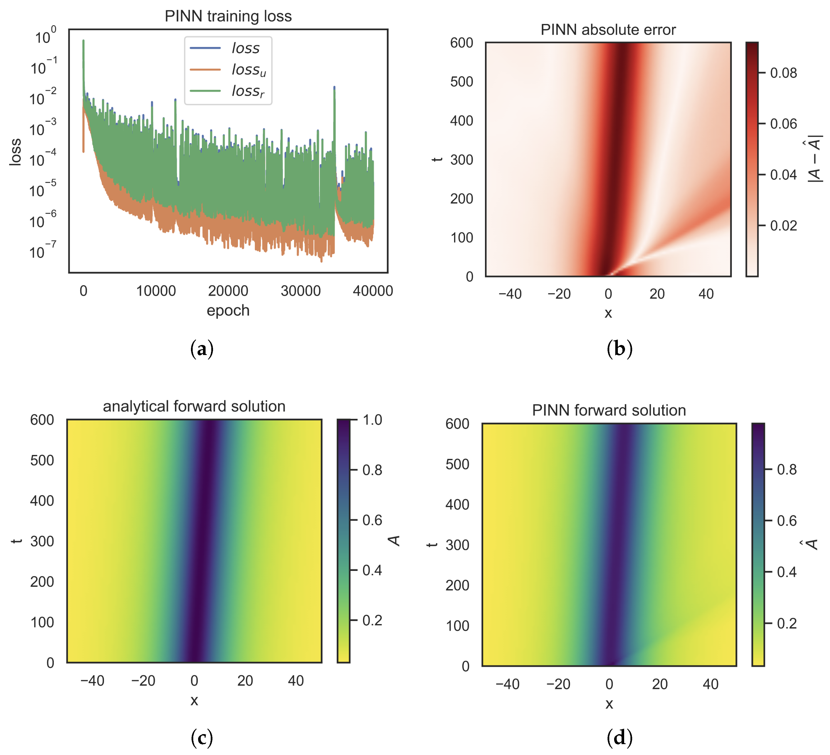
Figure 2 provides an overview of the PINN algorithm results, where
Figure 2a displays the loss function
L,
Figure 2b shows the heatmap of absolute error,
Figure 2c illustrates the equation’s exact solution, and
Figure 2d shows the solution obtained by the PINN. In the solution process of this paper, the parameter values used are
,
,
, and
. A relative
error of
was achieved, which indicates that the PINN can closely capture the soliton chasing behavior of the equation. Here,
: total loss function of the PINN;
: loss term corresponding to initial and boundary conditions;
: loss term representing the residual of the
equation.
Figure 3 shows the solution of the BDO equation. This equation is often used to describe long waves in shallow water, such as Rossby waves in the atmosphere. From the graph, we can observe that the amplitude
reaches peak values at certain points of
x and
t, while it gradually decreases in other regions. This suggests that the amplitude of Rossby waves fluctuates as influenced by terrain variations. Higher amplitude regions might correspond to areas where terrain elevations or wave enhancements occur, while lower amplitude areas may indicate regions where the impact of terrain on wave dynamics is weaker. The variation of amplitude with
t also shows the propagation and evolution of waves, likely linked to the influence of terrain on fluid dynamics. It should be noted that the current study focuses on presenting the qualitative laws of amplitude evolution of topographic Rossby algebraic solitary waves, and has not yet fully completed the quantitative calculation of wave velocity under different parameters. Additionally, the quantitative characterization of the parameter influence on wave amplitude still needs improvement, resulting in the unclear presentation of the regulatory effect of parameters on wave velocity and the specific influence degree on wave amplitude. Future studies will further optimize the wave velocity extraction method, supplement the quantitative analysis of amplitude differences under multiple parameter sets, and systematically clarify the regulatory mechanism of parameters on wave amplitude and wave velocity to improve the conclusions of this study.
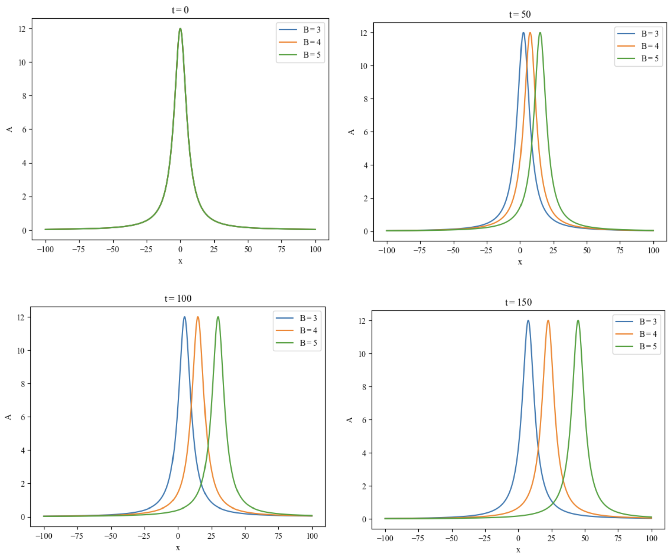
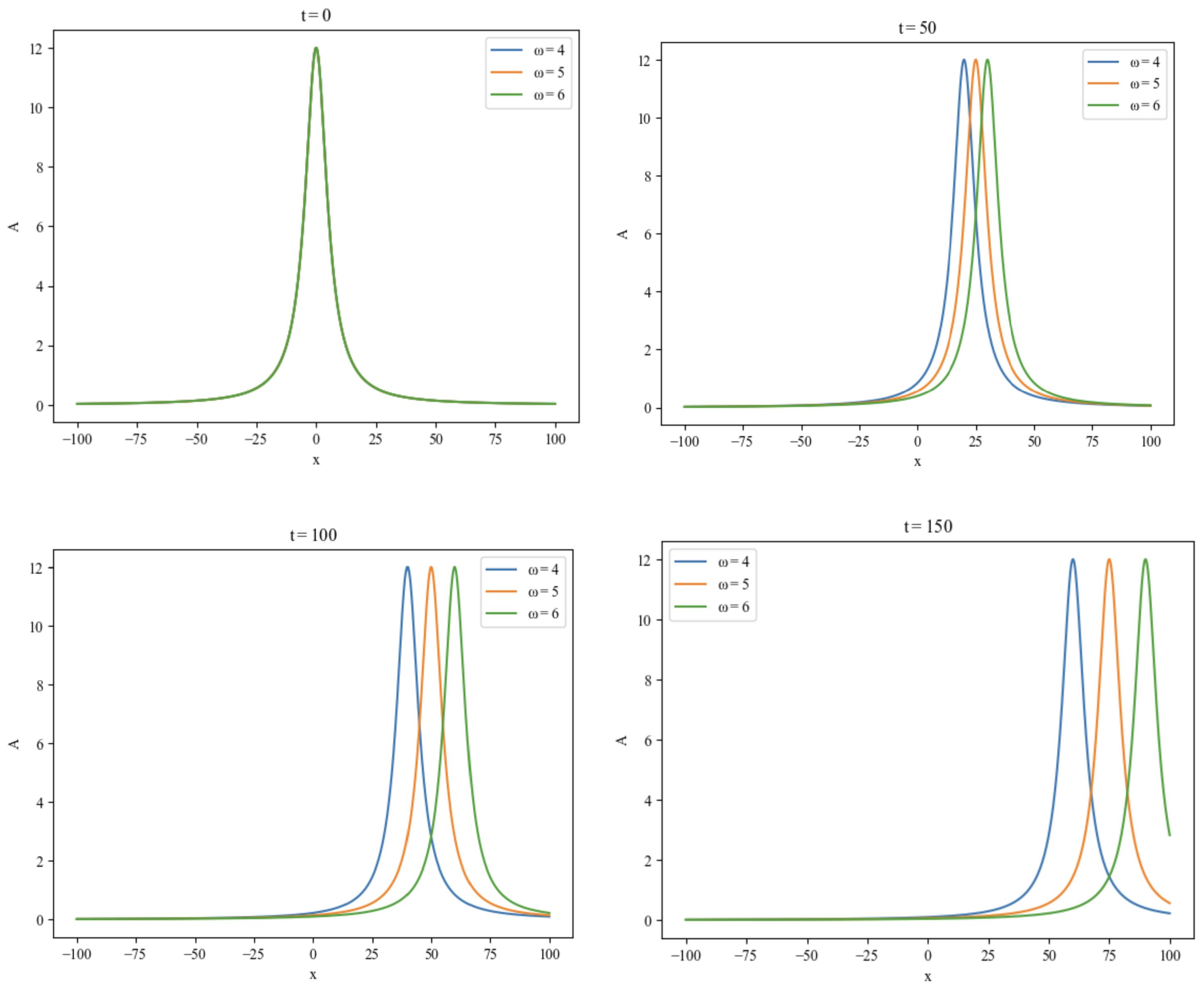
Figure 4 and
Figure 5 illustrate how terrain parameters affect the Rossby wave’s amplitude
A over time, with epsilon fixed at
and
B values of 3, 4, and 5, and
values of 4, 5, and 6. The figures indicate that changes in
B and
influence wave speed, thus impacting terrain and, in turn, amplitude
A. Higher
B and
values correspond to a greater effect on wave speed. Over time, the rightward movement becomes faster, concentrating energy and enhancing wave propagation speed.
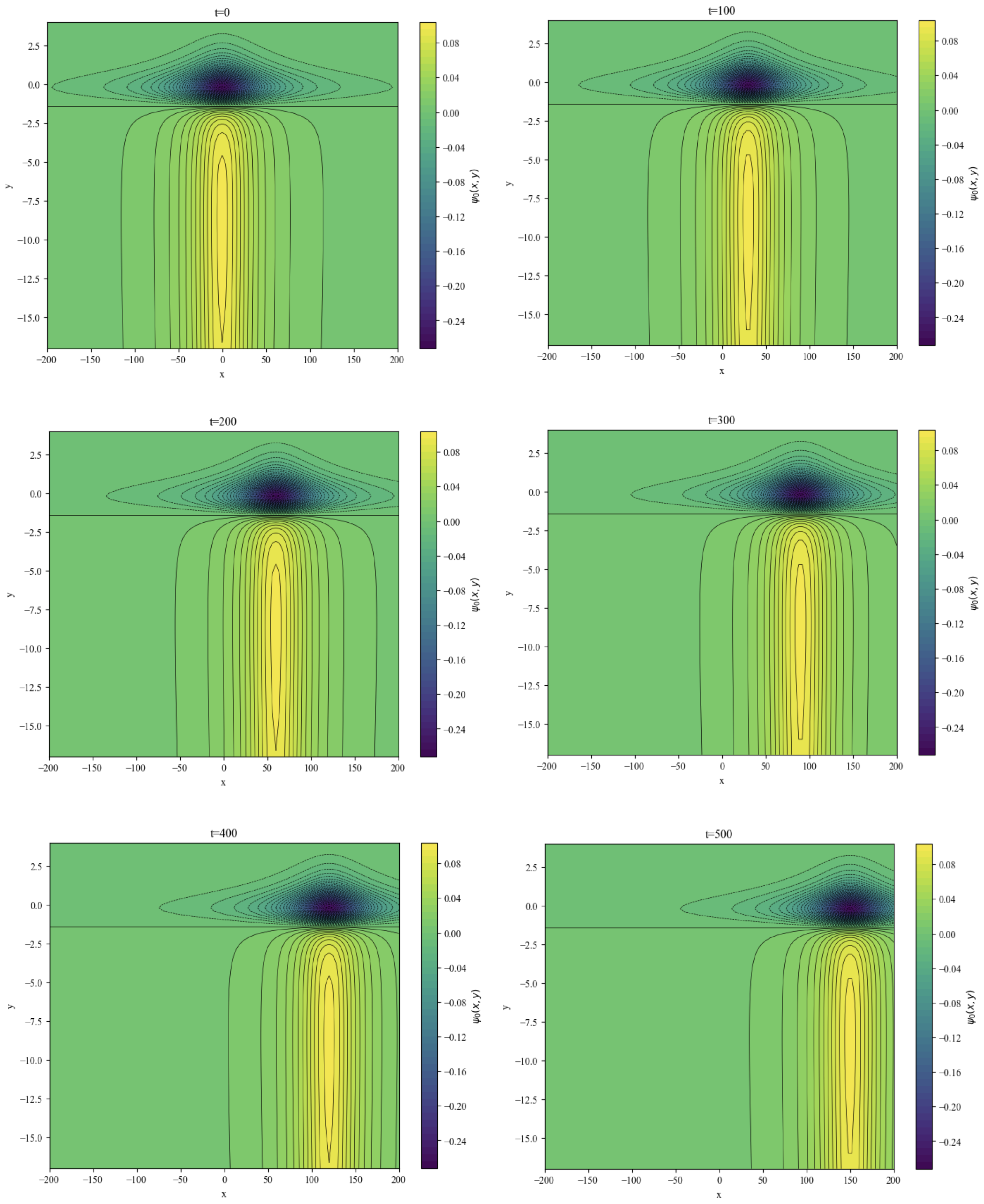
Figure 6 displays contour maps of the perturbation stream function
at different time instants under
. The spatiotemporal evolution of the contour structures reflects variations in the topographic configuration of the Rossby solitary wave. At
, the stream function contours exhibit symmetric distribution centered along the x-axis, with well-defined peaks and troughs indicating maximum wave amplitude and concentrated topographic influence, characteristic of a canonical Rossby wave pattern.
As time advances, the wave structure shifts rightward while retaining its morphological stability—suggesting efficient energy propagation without significant structural distortion. This stable translation likely arises from the dynamic balance between topographic forcing and background flow, where the Coriolis effect and topographic steering collectively maintain directional propagation stability.
The terrain-modulated wave behavior observed here—including stable contour translation and asymmetric inner-region distributions—establishes a baseline for investigating multifactor coupling effects. Subsequent studies may extend this framework by incorporating thermal forcing into the shallow-water system, thereby exploring synergistic terrain–thermal regulation of wave trajectories. Such expansions would advance the dynamics of Rossby waves in complex environments, whereas the present study remains focused on quantifying topographic modulation in isolation.
4. Conclusions
This study investigates topographic Rossby algebraic solitary waves (TRASWs) in mid-to-high-latitude geophysical fluids, with the aim of establishing a theoretical model for their amplitude evolution. Starting from the shallow-water equations governing rotating fluid motion, the model incorporates the shallow-water approximation, -plane approximation, and weak nonlinear perturbation methods. Through nondimensionalization and matching of inner and outer regional solutions, a dimensionless BDO equation is derived. This equation includes a nonlinear amplitude term, a linear phase speed term, and a Hilbert transform dispersion term, providing a quantitative description of the topographic modulation of TRASW amplitude and filling a theoretical gap in the modeling of algebraic solitary waves under weak to moderate topographic conditions.
The study employs a Physics-Informed Neural Network for validation. The PINN simulation results show a relative error of only compared to the theoretical solution, effectively avoiding numerical dispersion issues associated with traditional methods and confirming the validity of the BDO-type equation.
However, the study has certain limitations: the quantitative influence of topographic parameters on wave amplitude remains inadequately characterized, and wave speed calculations have not been addressed. Future work will focus on optimizing topographic parameterization, quantitatively evaluating the effects of topography on wave amplitude and speed, and incorporating temporal variations in background flow fields to further refine the dynamical theory of TRASWs.
