Abstract
The article examines the problems associated with the use of waste thermal energy. A new concept is developed on how to improve an atmospheric condensing engine by using low-temperature waste thermal energy, converting it into energy acceptable to the consumer (mechanical, electrical energy). The article presents a new scheme of a staged atmospheric condensing engine, thanks to which (based on preliminary calculations and recuperator verification experiments) it is possible to increase the efficiency of the condensing engine from 6.3% to 17%. At low temperatures (80–150 °C) this is a very high efficiency, since devices operating at low temperatures, for example, devices operating on the Rankine cycle, only have an efficiency of about 4.2–9%.
1. Introduction
Carbon dioxide and low-temperature thermal energy (80–150 °C) are still emitted into the atmosphere in large amounts by various industries and the energy sector in various forms—exhaust gases, hot air, and water vapour. According to the WHO (World Health Organization), approximately 91% of the world’s population lives in conditions of increased air pollution. Despite the rapid development of clean energy technologies, the fossil fuel-based energy sector remains one of the largest polluters [1,2]. During the past decades, approximately 80% of the world’s primary energy consumption has come from fossil fuels [2], which must be burnt to generate energy. Even buildings that seem to operate environmentally friendly processes sooner or later emit thermal energy into the environment. All of this not only pollutes the environment but also causes even greater consequences of climate change. The potential of low-temperature geothermal energy sources is also underutilized, as only high-temperature thermal energy (above 150 °C) is used for energy production, while low-temperature energy is typically released into the environment. The amount of energy wasted in the global economy is very high. When comparing global primary energy with usable energy flows, studies show that about 72% of it is wasted during conversion [3]. Various technologies are being developed and improved, with the help of which it would be possible to produce commercially viable energy from low-temperature waste heat (LTWH) [4,5,6,7,8,9,10,11]. The most famous of these is the organic Rankine cycle (ORC), but recently researchers have turned their attention to condensing engines, such as the Newcomen atmospheric engine (NE) and the Watt condensing steam engine (CE) [7,8,9,10,11,12,13,14,15,16,17]. These engines have long been out of use and were considered hopelessly obsolete due to their low efficiency and poor weight-to-size-to-power ratio. However, issues related to climate change, environmental pollution, and limited energy resources require a new look at the advantages and disadvantages of condensing engines.
With respect to the ORC, it should be emphasized that its efficiency at low temperatures is also low. For example, in the operating temperature range of 80–110 °C, the efficiency ranges from 4.2 to 6.8% [7,18]. The complexity of ORC systems and the associated costs have so far prevented the wider use of LTWH. In addition, ORC systems use fluids with a high Global Warming Potential (GWP), while condensing engines use water. Another problem with ORC is the turbine. The turbine requires high pressures [12], while a condensing engine can use as little as 1 bar pressure. The problems of low efficiency remain to be solved, and CE would compete with the ORC due to its simplicity of design, cheapness, and process safety (low temperatures, low pressures). However, the most important aspect is that CE is incomparably more environmentally friendly than ORC.
The aim of this paper is to present a concept (improved design of a condensing engine) on how to increase the efficiency of a condensing engine. In addition, based on the mathematical modelling and experimental data of the authors and other condensing engine researchers, the aim is to perform preliminary calculations of the efficiency of the proposed engine and verification of the recuperator, which would show whether this concept can be further developed.
2. Condensing Engine Efficiency
Recently, there has been an increase in research related to the calculations of the efficiency of the condensing engine— both theoretical and experimental studies. Opportunities are being sought not only to increase the efficiency of the CE, but also to make it significantly higher than that of the ORC. For a very long time, the concept that only a few parameters are relevant when calculating the efficiency of NE and CE was followed: energy to raise the temperature of the water from the initial temperature to the boiling point; energy to evaporate the water; and mechanical energy created due to the difference in pressure between atmospheric pressure and low pressure after condensation of steam [19]. The energy that is removed from the process as condensation energy was considered an inevitable loss—such a concept existed even until the 21st century. The situation has changed in the last decade. When reviewing how the methods for calculating CE efficiency have evolved and what measures have been proposed to increase it, the CE efficiency coefficient should first be calculated in the classical way [20]. We will not consider NE, because due to the cyclic filling of the cylinder with steam at a temperature of 100 °C (or slightly higher) and cyclic cooling by injecting cold water into the cylinder, the real efficiency is only about 1% [12]. The following methods are commonly used to determine the efficiency of CE (as well as any heat engine) [7,9,15,20]:
(1) Thermal efficiency is the ratio of the mechanical power obtained at the output to the thermal energy consumed at the input :
(2) Net thermal efficiency (ηnet) is the net useful power divided by the thermal energy input . Net useful power is the useful engine power minus the energy demand Wp of system components, such as working fluid pumps, that are necessary for the system to operate [7]:
(3) Carnot efficiency —the maximum theoretical efficiency of a heat engine. It is calculated between the highest and lowest temperatures in the system (between the evaporator and the condenser measured on the Kelvin scale:
(4) Efficiency according to the second law of thermodynamics —thermal efficiency as a percentage of the Carnot efficiency. shows the ability of the system to convert available thermal energy into useful energy. This allows a direct comparison of the efficiency of different technologies operating at different temperature levels and ranges:
Analyzing all four calculation methods in a complex manner and applying them to CE, the question of the Carnot coefficient arises. The principle of operation of CE is based on pressure changes between the boiling and condensation points. We must evaporate the liquid (in this case, water) and then condense it, otherwise the engine will not work. It is understood that this process requires thermal energy not only to raise the temperature of the water to the boiling point (in the case of CE—up to 100 °C, at a pressure of 1 bar), but also to provide incomparably more thermal energy for the change in the phase of the liquid—the evaporation of water. We cannot look at formula (3) as a universal method for calculating CE efficiency, because it does not contain latent heat. This fact also encourages us to look for ways to recover latent heat back into the process. Let us examine this problem. We will not examine the principle of operation of NE or CE, it has been examined in many works [7,8,9,11,12,13,16,17], but we will pay attention to the heat that is removed from CE by water intended for steam condensation , (Figure 1). Let us preliminarily calculate from which components the thermal energy is formed, which is removed by water .
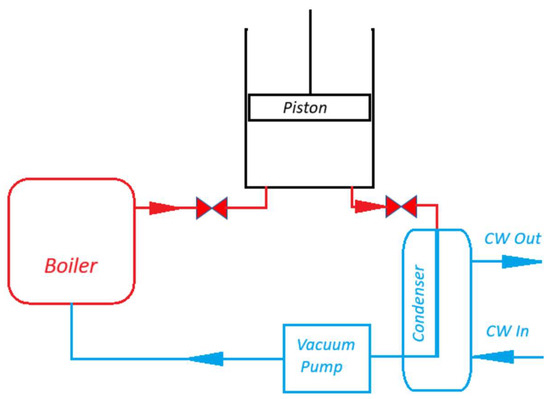
Figure 1.
Schematic diagram of a condensing engine.
Let us assume that we will use water as the working fluid, prepare steam at atmospheric pressure, not raise the temperature of the prepared steam above 100 °C, condense at 30 °C, and ignore heat losses to the environment, friction, vacuum pump, and other losses. We will choose the CE parameters (cylinder volume and piston stroke) as in [13,20]: an idealized cylinder A with a cross-sectional area of 1 m2, a stroke of L = 1.69 m, and containing 1 kg of steam at a temperature of 100 °C. The condensation pressure of water vapour at 30 °C is approximately 0.04 bar or 4 kPa. To simplify the calculation, we will round the atmospheric pressure to = 100 kPa. Such pressure acts on the piston and pushes it during one stroke. At that time, useful mechanical work is created:
The mechanical work performed by 1 kg of water vapour (mw) under ideal conditions would be 162.2 kJ. It is easy to calculate how much thermal energy would be needed to do this work. When the specific heat capacity of water is = 4.18 kJ/kg∙K and the latent heat is = 2257 kJ/kg:
It is obvious that the thermal efficiency according to (1) would be 0.063; Carnot efficiency: 0.19; and efficiency according to the second law of thermodynamics: 0.33.
It is a suitable time to ask the question, why is the thermal efficiency so low? After all, we have assumed that there will be no heat loss to the environment, we have ignored friction, and we have not estimated the energy for the pump, losses in valves, etc.
The answer can be seen in the formula and calculation (6). The energy required to evaporate a kilogram of water is up to 7.7 times greater than the energy required to raise the temperature of a kilogram of water from 30 °C to 100 °C. In addition, the energy to raise the temperature of water from the initial to the boiling point can easily be recovered from the process. Unfortunately, attempts to recover latent energy and use it again for the evaporation of water in a condensing engine are only made in the first steps [9].
In the CE process, two phase transformations occur—evaporation and condensation. The same amount of energy is used to evaporate water, and the same amount is utilized in the condenser. If it were possible to return part of the latent energy to the CE process, the efficiency would increase significantly. However, there is a problem—evaporation occurs at 100 °C, and condensation at significantly lower temperatures (e.g., in our calculated case, at 30 °C). Such an amount of cold water must flow through the condenser (Figure 1) to constantly maintain 30 °C. This is a large amount of water [14], because it must absorb all the thermal energy of condensation of the steam leaving the cylinder. However, let us note that after the process has stabilized (say, the cylinder and piston have already heated up to close to 100 °C during operation and are maximally thermally insulated), the steam will leave the cylinder at almost 100 °C (in cases with steam expansion in the cylinder, the situation is different; we will discuss this later). If waste steam from production processes is supplied to the CE, it may be at a temperature higher than 100 °C, so steam at 100 °C or even slightly more than 100 °C may exit the cylinder. Steam exits the cylinder through channels (Figure 1), which are classified as the hot zone of the CE process [7]. By installing a counter-flow heat exchanger in these channels, it is possible to partially recover latent heat not at a temperature of 30 °C, but gradually from 100 °C to 30 °C. Figure 2 presents a schematic diagram showing an atmospheric CE with an expanded channel between the cylinder and the condenser. By installing a heat exchanger in the upper part of this channel, through which condensate is supplied from the vacuum pump, it would be possible to collect some of the latent heat. The amount of this heat would depend on the design features of the heat exchanger and the materials from which it is constructed. Therefore, the heat exchanger must fulfil the following conditions: it must provide minimal resistance to the steam flow exiting the cylinder; it must be maximally isolated from the environment; it must create minimal resistance to the vacuum pump; it must be designed so that steam does not have the opportunity to bypass the heat exchanger; steam should pass evenly through the heat exchanger so that the temperature drops gradually (Figure 2); condensate formed at any stage should not fall into the condenser, but should, like steam, gradually descend downwards, giving off thermal energy; a temperature difference should remain between the steam outside and the condensate inside at each stage to maintain the condensation process; and maximally cooled water from the condenser must enter the vacuum pump. If these conditions are met, a relatively small amount of heat would remain in the heat exchanger at the bottom, which performs the function. The steam would give off latent thermal energy and flow downwards towards the condenser in the form of a liquid. Here, the term “condenser” is no longer even appropriate, since the function of condensing most of the steam would be performed by the recuperator. The condenser at the bottom would perform the final cooling function, cooling the water to the required temperature, e.g., to 30 °C. Therefore, the amount of thermal energy would only leave the process as determined by the temperature difference between the set 30 °C and the condensate flowing out of the recuperator. Under the pressure of the vacuum pump, the condensate would rise upwards, gradually heating up. Part of the water would turn into steam. The ratio between water/steam would depend on the efficiency of the recuperator. This water and steam mixture would be returned to the boiler.
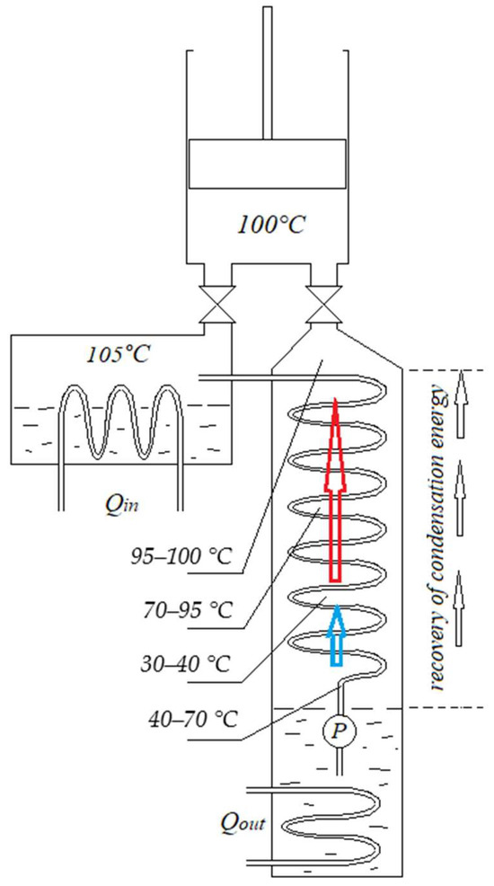
Figure 2.
Diagram of a condensing engine with a recuperator. Qin—thermal energy input; Qout—thermal energy output; P—vacuum pump.
For example, if we were to calculate the CE of such parameters as we calculated and were able to recover all the latent energy, then the following applies:
We see that instead of 2549.6 kJ per cycle, the CE will require only 292.6 kJ, and the thermal efficiency will increase from 0.063 to 0.55 (of course, this is just a hypothetical scenario). It is difficult to expect to recover 100% of the latent energy at different pressures in the recuperator and inside the recuperator tube (in the recuperator it will be lower than inside the tube). In addition, the pressure in the recuperator and condenser must be low (0.1–0.4 bar). Therefore, the steam pressure, going from the upper part of the recuperator to the lower part, will gradually decrease and heat recovery will deteriorate (in addition, the latent energy will increase slightly [20]). Therefore, such a single-stage (Figure 2) latent energy recovery, from a physical and engineering point of view, is possible only to a relatively small extent [9].
The next step to increasing CE efficiency is the forced expansion of steam in the cylinder. It has been proven [7,13,15,16] that theoretically it is possible to increase the efficiency of a CE from 0.063 to 0.16, and in some cases even up to 0.20. The fact that introducing an additional stroke with steam expansion significantly increases efficiency has also been confirmed by experiments [16]. It is also known that a CE can operate at temperatures lower than the boiling point of the working fluid at atmospheric pressure, and this is fully or partially combined with forced steam expansion [7,13,16,17]. For example, a CE using water operates in a boiler maintaining a temperature of 60–100 °C. Next, we will present a scheme in which, by combining forced steam expansion and heat recovery, it is possible to significantly increase the efficiency of a condensing engine.
3. Staged Condensing Engine Design
We have drawn up a schematic diagram of a multi-cylinder CE (patent application LT 2025 553 [11]), in which only the first cylinder does not use forced steam expansion, while the others operate with forced steam expansion (Figure 3).
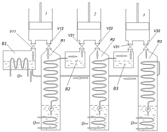
Figure 3.
Schematic diagram of a staged condensing engine with energy recovery [11]. 1—first cylinder; 2—second cylinder; 3—third cylinder; B1—first stage boiler; V11—first stage steam inlet valve; V12—first stage steam outlet valve; R1—first stage recuperator; B2—second-stage boiler; V21—second stage steam inlet valve; V22—second stage steam outlet valve; R2—second stage recuperator; B3—third stage boiler; V31—third stage steam inlet valve; V32—third stage steam outlet valve; R3—third stage recuperator; P—vacuum pump; Qin—thermal energy input; Qout—thermal energy output.
In an engine of this design, several cylinders can be mounted on the crankshaft. The heat used in the first cylinder and recovered by the recuperator can be used in the second cylinder, and from the second to the third, etc. The number of cylinders can be increased until the last cylinder reaches a water temperature such that it becomes impractical to generate mechanical energy. Then, the condensate from the last recuperator is returned to the first boiler.
Let us preliminarily calculate the amounts of energy transformed in such an engine (Figure 3). For easier comparison, let us take the CE already calculated: an idealized cylinder with a cross-sectional area of 1 m2, a stroke of L = 1.69 m, and containing 1 kg of steam at a temperature of 100 °C. The condensation pressure of water vapour at 30 °C is approximately 0.04 bar or 4 kPa. For the sake of simplicity, let us round the atmospheric pressure to = 100 kPa. We have already calculated (5) that such an engine will create 162.2 kJ of mechanical energy and consume 2549.6 kJ of thermal energy during one working stroke. When valve V12 opens (Figure 3) and piston 1 moves down, steam at a temperature of 100 °C will enter recuperator R1. The steam will move down and begin to condense on the recuperator tube. The steam temperature in the recuperator will gradually drop from 100 °C to 40 °C (Figure 2), and the pressure will also drop from 1 bar to 0.04 bar, as the condensate with a temperature of 30 °C is pumped into the recuperator. Then, if we calculate the recovered thermal energy (of course, in an idealized case) according to the following Equation (6):
Only 204 kJ of energy would remain to be utilized for the condenser heat exchanger . The numbers are very optimistic, but what numbers could be achieved in a real engine? When examining the steam–water heat exchangers currently on the market, we notice that some manufacturers declare up to 97% thermal energy transfer from steam to water (of course, only under limited conditions—low flow rate, low pressure, steam temperature not exceeding 100 °C, low cooler temperatures, minimal pressure difference between the condensed and evaporated liquid, etc.). But our case is very similar—relatively low condensate temperature (30 °C), steam temperature about 100 °C, pressure just 1 bar. The flow rate would determine the dimensions of the heat exchanger and the design features. In part of the heat exchanger, there will be such a pressure difference between the condensing and evaporating liquid that it will not allow the steam leaving the cylinder to condense completely; therefore, detailed modelling and experimental studies related to a new design of recuperator are required. This recuperator must be adapted to the processes that occur in a staged condensing engine.
4. Discussion
For now, without going into details, and moving away from the optimistic 97% efficiency of the recuperator, let us assume that a heat exchanger designed for optimal engine operation would recover 80% of the thermal energy, then the following applies:
Therefore, a water and steam mixture which has 1876.5 kJ of thermal energy would enter boiler B2. It is difficult to predict what the temperature of this mixture would be. Theoretically, it could be 100 °C, because at the beginning of the process we had 1 kg of steam at a temperature of 100 °C. Now we have about 0.73 kg of a water and steam mixture. Why not 1 kg, but 0.73 kg? When modelling the process in the second boiler and cylinder, let us use forced steam expansion [7,13,15,16]. There are several reasons for this: first—in boiler B2 there is no longer steam, but a mixture of steam and water; second—CE with steam expansion has better efficiency; third—the engine design will be simpler and cheaper if all cylinders are the same (there are other reasons too; more details are provided later). When valve V21 opens and piston 2 rises, the pressure in the boiler will drop and steam will flow into cylinder 2. The condensate residue in boiler B2 will boil when the pressure drops and will also fill cylinder 2. In the second cylinder, we have approximately 73 percent (0.73 kg) of the steam in the first cylinder (1 kg). This means that the forced expansion coefficient R [17] is approximately 1.37. According to [17], at R = 1.37 and an initial steam temperature in the boiler of 100 °C, the thermal efficiency of the CE is about 0.085. This means that from 1876.5 kJ of thermal energy, the second cylinder will generate 159.5 kJ of mechanical energy. Paradoxically, almost the same as the first cylinder. Theoretically, this is possible because we did not apply forced expansion in the first cylinder. The first cylinder worked with a lower efficiency (0.063), but more thermal energy remained for recovery and was used with better efficiency in the second cylinder.
Let us calculate the energy for the third cylinder. It needs to be recovered from the second. However, if we were to calculate according to the same methodology that we applied to the second cylinder, we would obtain very inaccurate results. Since the second cylinder worked with forced steam expansion, when valve V22 opens, the pressure in the second cylinder will be less than 1 bar (and the temperature is significantly lower than 100 °C). Therefore, the pressure drop in the recuperator will not start from 1 bar (as it was in the first recuperator). This may affect the energy recovery, so let us preliminarily accept the condition that the recovery efficiency will not be 0.8, but 0.6. Having adjusted the calculation in this way, we find that we can still supply about 1030.2 kJ of energy to the third cylinder. Unfortunately, due to the aforementioned pressure drop, this thermal energy will not be at a temperature of 100 °C. However, as mentioned, CE can also work at lower temperatures, in combination with forced steam expansion [7,13,16,17]. Forced steam expansion will reduce the pressure in boiler B3. The boiling point of the water–steam mixture will decrease, and we would fill the third cylinder with a forced expansion coefficient R = 2. If we assume that the temperature can reach about 70 °C and that according to research [17] the theoretical efficiency of CE is about 0.078, from 1030.2 kJ of thermal energy we would obtain about 80 kJ of mechanical energy.
Thus, the mechanical energy generated in all three cylinders could be about 401.7 kJ. However, the third cylinder also has a recuperator, the efficiency of which could reach about 0.4. The recuperator would collect about 380 kJ of thermal energy from the third cylinder, which would be directed to the boiler of the first cylinder. However, this would be low-temperature thermal energy, which could only partially heat the boiler of the first cylinder (according to preliminary calculations, about 190 kJ). Therefore, the thermal efficiency of such a three-cylinder engine could tentatively be approximately the following:
The result of 0.17 is significantly less than the calculated theoretical of 0.55, but significantly more than conventional CE, which even has a theoretical efficiency of only 0.063.
When examining the T-S and p-V diagrams of a three-stage engine (Figure 4), we see that neither the consistency of temperature nor the entropy change are violated. This is visible in the diagrams, where the diagrams of all three stages are superimposed on each other—the temperature and pressure of each stage subsequent to the first are lower than the stages preceding it. The diagrams should not be viewed as an illustration of a specific engine with specific recuperators, because they are drawn as if 1 kg of water were used in each stage per cycle. In a real engine, the recuperated energy would be distributed in such a way that the residual condensation energy of the first and second cylinders would be fully utilized (in other words, different stages may rotate at different speeds, or their cylinder volumes may be different; the engine may not be atmospheric, but opposition, etc.).
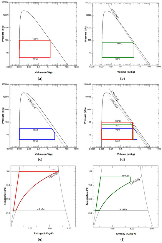
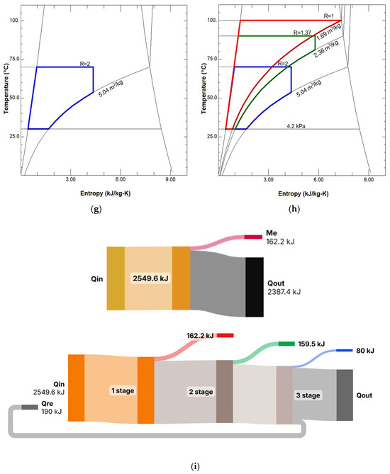
Figure 4.
P-V and T-s diagrams of a three-stage condensing engine: (a) p-V diagram of the first stage; (b) p-V diagram of the second stage; (c) p-V diagram of the third stage; (d) p-V diagrams of three stages; (e) T-s diagram of the first stage; (f) T-s diagram of the second stage; (g) T-s diagram of the third stage; (h) T-s diagrams of three stages; (i) Sankey diagrams for single-stage and three-stage engines: above—a diagram of a single-stage motor without condensation energy recovery, below—a diagram of a three-stage motor with condensation energy recovery. The diagrams show the processes per kilogram of water (in a real operating engine and in preliminary calculations, the amount of water in the second and third stages is less than 1 kg).
This article proposes a simplified scheme of a staged condensing engine (Figure 3), which only shows the principle of engine design of this type. The main problem is that the steam pressure in the recuperator drops quickly, and the condensation process occurs only partially. The authors of the article continue to improve the engine and research, generating ideas that help condense low-pressure steam in the recuperator more efficiently. Methods that improve steam condensation have already been developed and partially experimentally tested with the help of stands (Figure 5a), and these methods are being prepared for patenting. The first test results allow us to state that the calculated efficiency of 0.17 can also be proven experimentally (this only concerns recuperation, eliminating the imperfection of test stands—heat, steam, vacuum losses, friction losses, etc.). It should also be said that traditional static recuperator designs are not effective when the pressure change when steam leaves the cylinder (e.g., from 1 bar to 0.04 bar) occurs very quickly. When performing calculations of condensation processes and modelling the process, it is also necessary to assess the condition that the steam in the recuperator must condense while moving at a certain speed. Therefore, the next stage of research is the development and improvement of dynamic recuperators of a new design. The authors tested a prototype of a dynamic recuperator and compared its data with a conventional static design recuperator (Figure 5b). With the help of the stand (Figure 5a), steam was supplied to the recuperator from the condensing engine into a glass tank and the work of the second stage of the engine was simulated in it (Figure 6): the tank played the role of a second stage boiler.

Figure 5.
(a) Photo of an experimental condensing engine stand: 1—boiler; 2—condenser; 3—recuperator; 4—circulation pump; 5—fan coil; 6—vacuum pump; 7—generator; 8—condensing engine with flywheel; 9—data logger; (b) the amount of steam condensation (in grams) of the classic 2 (red) and dynamic 1 (blue) recuperators when 140 G of water is supplied to the recuperators.
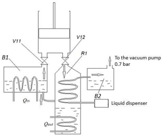
Figure 6.
Scheme of experimental verification of the recuperator. B1—boiler; V1—steam inlet valve; V2—steam outlet valve; R1—recuperator; B2—second-stage boiler. The vacuum pump simulates the second stage of the engine, which operates on the principle of expanded steam. The liquid dispenser supplies water in a uniform mode over a fixed time. The scheme shows a recuperator operating on the classical principle.
The operation of the second stage with expanded steam (at a pressure of 70 kPa) was simulated using a vacuum pump. The tests were carried out after the engine had fully warmed up to operating temperature, and a fixed amount of water was supplied to the recuperator for a fixed time. The amount of evaporated water was determined from the amount of condensate remaining in the boiler B2 (Figure 6).
The capabilities of conventional, statically operating, and dynamic recuperators to condense the water of the first stage and evaporate the water of the second stage, when the temperature difference reaches up to 10 °C, are shown in graphs 1 and 2 (Figure 5b). The graphs show the amount of evaporated water in the recuperators (in grams), when 140 g of water was supplied evenly over a fixed time. The results of conventional and dynamic recuperators are clearly different. When the results are converted into percentages, the 80% expected in our preliminary calculations does not occur, but it is necessary to assess the imperfections, leaks, and lack of optimization of the design.
5. Conclusions
This article presents the idea of a staged condensing engine, preliminary calculations, and partial verification of the process. However, the following conclusions can already be formulated:
1. A new design of a staged condensing engine is proposed, in which steam condensation energy is recovered and reused.
2. A preliminary calculation of the efficiency of a three-stage condensing engine is presented, making assumptions about possible recovery conditions in a real engine, which reduce efficiency. The efficiency obtained still significantly exceeds the theoretical efficiency of a conventional condensing engine (the preliminary calculated efficiency of a staged condensing engine is 0.17, compared to the conventional 0.063).
3. Preliminary experiments have shown that the traditional design of a vapour–liquid recuperator does not allow for the effective recovery of the latent energy of liquid condensation; therefore, for such processes, it is necessary to develop a new concept of recuperators: dynamic recuperators.
4. A staged condensing engine with steam condensation energy recovery could be a good way to usefully utilize low-temperature thermal energy and produce useful energy to the consumer while protecting the environment. Therefore, it can be stated that detailed process modelling, optimization, and experimental research have good prospects.
6. Patents
During the research described in this article, a schematic diagram of a staged condensing engine with energy recovery was created and patent application No. LT 2025 553 was submitted to the Lithuanian State Patent Office.
Author Contributions
Conceptualization, A.R. and M.R.; methodology, A.R., M.R., R.B. and A.Č.; software, A.R., M.R., R.B. and A.Č.; validation, A.R., M.R., R.B. and A.Č.; formal analysis, A.R. and M.R.; investigation, A.R., M.R., R.B. and A.Č.; resources, A.R., M.R., R.B. and A.Č.; data curation, A.R., M.R., R.B. and A.Č.; writing—original draft preparation, A.R.; writing—review and editing, A.R., M.R., R.B. and A.Č.; visualization, A.R., M.R., R.B. and A.Č.; supervision, A.Č.; project administration, A.Č.; funding acquisition, A.Č. All authors have read and agreed to the published version of the manuscript.
Funding
This research received no external funding.
Institutional Review Board Statement
Not applicable.
Informed Consent Statement
Not applicable.
Data Availability Statement
The data that support the findings of this research are available from the authors upon reasonable request.
Conflicts of Interest
The authors declare no conflicts of interest.
References
- Ge, M.; Friedrich, J.; Vigna, L. 4 Charts Explain Greenhouse Gas Emissions by Sector. 2024. Available online: https://www.wri.org/insights/4-charts-explain-greenhouse-gas-emissions-countries-and-sectors (accessed on 16 February 2025).
- International Energy Agency. World Energy Outlook 2023: Pathways for the Energy Mix, International Energy Agency. Tech. Rep. 2023. Available online: https://iea.blob.core.windows.net/assets/66b8f989-971c-4a8d-82b0-4735834de594/WorldEnergyOutlook2023.pdf (accessed on 28 January 2025).
- Forman, C.; Muritala, I.K.; Pardemann, R.; Meyer, B. Estimating the global waste heat potential. Renew. Sustain. Energy Rev. 2016, 57, 1568–1579. [Google Scholar] [CrossRef]
- Kumar, A.; Rakshit, D. A critical review on waste heat recovery utilization with special focus on Organic Rankine Cycle applications. Clean. Eng. Technol. 2021, 5, 100292. [Google Scholar] [CrossRef]
- Sohrabi, A.; Liu, S.; Cuce, E.; Shen, Y.; Khan, S.Y.; Kumar, M. Utilization of low-grade thermal energy for residential applications: A review of the existing and potential technologies. Renew. Sustain. Energy Rev. 2025, 219, 115832. [Google Scholar] [CrossRef]
- Thiel, G.P.; Stark, A.K. To decarbonize industry, we must decarbonize heat. Joule 2021, 5, 531–550. [Google Scholar] [CrossRef]
- Muller, G.; Howell, C. Comparative analysis of ORC and condensing heat engines for low grade waste heat recovery. Appl. Eng. 2021, 5, 29–35. [Google Scholar]
- Wang, Y.; Zhou, Z.; Zhou, J.; Liu, J.; Wang, Z.; Cen, K. Micro Newcomen steam engine using two-phase working fluid. Energy 2011, 36, 917–921. [Google Scholar] [CrossRef]
- Rotmanas, M. Increasing the Efficiency of an Atmospheric Steam Engine by Recuperating the Latent Heat of Condensation. Master’s Thesis, Delft University of Technology, Delft, The Netherlands, August 2025. [Google Scholar]
- Rotmanas, A.; Rotmanas, M.; Bareikis, R.; Gedzevicius, I. Opposed Cold Steam Engine and Method of Operation, EP4509701A1. Available online: https://patents.google.com/patent/EP4509701A1 (accessed on 20 February 2025).
- Rotmanas, A.; Rotmanas, M. Pakopinis Kondensacinis Variklis su Energijos Rekuperavimu ir jo Veikimo Būdas, Patento Paraiška Nr. LT 2025 553; Lietuvos Valstybinis Patentų Biuras: Vilnius, Lithuania, 2025. [Google Scholar]
- Müller, G.; Mereš, B. Assessment of the Newcomen engine’s development potential as heat engine for low temperature waste heat. Power Energy 2023, 237, 1577–1584. [Google Scholar] [CrossRef]
- Muller, G. The atmospheric steam engine as energy converter for low and medium temperature thermal energy. Renew. Energy 2013, 53, 94–100. [Google Scholar] [CrossRef][Green Version]
- Mitrovic, J. Some ideas of James Watt in Contemporary Energy Conversion Thermodynamics. J. Mod. Phys. 2022, 13, 385–409. [Google Scholar] [CrossRef]
- Bortolin, V.; Andreghetto, A.; Lemos, B.L.H.D.; Amaral, R.d.L.; Freire, C.M.; Meneghini, J.R. Thermodynamical model of an atmospheric steam engine. J. Braz. Soc. Mech. Sci. Eng. 2021, 43, 493. [Google Scholar] [CrossRef]
- Müller, G.; Parker, G. Experimental investigation of the atmospheric steam engine with forced expansion. Renew. Energy 2015, 75, 348–355. [Google Scholar] [CrossRef]
- Müller, G.; Chan, C.H.; Gibby, A.; Nazir, M.Z.; Paterson, J.; Seetanah, J.; Telfer, M.; Tsuzaki, T.; Walker, C.; Yusof, F. The condensing engine: A heat engine for operating temperatures of 100 and below. AJ Power Energy 2018, 232, 437–448. [Google Scholar] [CrossRef]
- Landelle, A.; Tauveron, N.; Haberscill, P.; Revellin, R.; Colasson, S. Organic Rankine cycle design and performance comparison based on experimental database. Appl. Energy 2017, 204, 1172–1187. [Google Scholar] [CrossRef]
- Guyonneau de Pambour, F.M.; Schnuse, C.H. Neue Theorie der Dampfmaschine, Oder Vollständige Anleitung zur Berechnung des Effectes und der Dimensionen Aller Arten von Dampfmaschinen: Nebst Eines Anhanges. Meyer Verlag, Braunschweig. 1839. Available online: https://digital.deutsches-museum.de/item/BV023304784/ (accessed on 5 September 2025).
- Dietzel, F.; Wagner, W. Technische Wärmelehre Technical Thermodynamics, 9th ed.; Vogel Verlag: Würzburg, Germany, 2006. [Google Scholar]
Disclaimer/Publisher’s Note: The statements, opinions and data contained in all publications are solely those of the individual author(s) and contributor(s) and not of MDPI and/or the editor(s). MDPI and/or the editor(s) disclaim responsibility for any injury to people or property resulting from any ideas, methods, instructions or products referred to in the content. |
© 2025 by the authors. Licensee MDPI, Basel, Switzerland. This article is an open access article distributed under the terms and conditions of the Creative Commons Attribution (CC BY) license (https://creativecommons.org/licenses/by/4.0/).