1. Introduction
In contemporary geographic information and remote sensing science, the digital surface model (DSM) and digital elevation model (DEM) stand as indispensable tools employed for the examination of surface terrain and topographical features. These models not only furnish data support for endeavors such as forest monitoring [
1] and urban planning [
2] but also play a pivotal role in military [
3], aviation [
4,
5], and related domains.
Satellite-borne interferometric synthetic aperture radar (InSAR) is a vital tool for global mapping endeavors. In the year 2000, the United States launched the space shuttle “Endeavour” carrying the world’s first spaceborne topographic mapping mission system, known as the “Shuttle Radar Topography Mission” (SRTM) [
6]. This mission employed a single-pass dual-antenna InSAR configuration, showcasing the remarkable performance of InSAR technology in topographic mapping. Operating in the C-band and X-band radar frequencies, the SRTM mission successfully conducted topographic mapping across all terrestrial regions between 60° N and 56° S. The STRM DEM met the standards of high-resolution terrain information-2 (HRTI-2), attesting to the mission’s achievement in providing high-resolution terrain information [
7,
8]. The Deutsches Zentrum für Luft- und Raumfahrt (DLR) successively launched the TerraSAR-X satellite and the TanDEM-X satellite in 2007 and 2010, respectively [
9]. These two satellites constitute the world’s first spaceborne formation-flying distributed InSAR system, conducting over three years of high-precision global land DEM measurement missions, and the TanDEM DEM met the HRTI-3 standard [
10]. Compared to the SRTM mission, the TerraSAR-X constellation extends the coverage of terrain mapping globally, thus serving as the new generation global DEM foundational dataset. Subsequently, Subsequently, more countries commenced launching satellites to accomplish their respective mapping missions. For instance, Canada launched RADARSAT-2 in 2007 [
11], Italy launched COSMO in 2007 [
12], and Japan launched ALOS-2 in 2014 [
13].
Imaging is the most crucial task in the ground processing of SAR satellites. In 1998, Soumekh first discussed the lack of distinct Doppler spreading in the echo signals, which made it difficult to utilize conventional pulse or FM-CW SAR imaging algorithms. Soumekh proposed time domain correlation (TDC) processing and Fourier-based methods for image formation in WB-CW monostatic and bistatic SAR systems [
14]. In 2009, Zhou et al. introduced a new algorithm based on complex empirical mode decomposition (CEMD), focusing on the suppression of narrow band interference (NBI) in SAR imaging. By using traditional SAR imaging algorithms to separate target echoes, focused SAR images could be obtained from the suppressed NBI signals [
15]. Later, in 2013, Gianelli et al. proposed a simple method for focusing phase history data in SAR imaging [
16]. By 2015, Bu et al. introduced a new SAR imaging algorithm based on compressed sensing (CS), effectively reducing the number of measurements required for SAR data acquisition [
17]. The CS algorithm also provided a computationally efficient solution for focusing bistatic forward-looking SAR [
18]. Subsequently, researchers focused on addressing image distortion in near-field bistatic SAR imaging caused by using equivalent monostatic approximation algorithms [
19], such as the extended NLCS algorithm proposed to improve Doppler resolution and mitigate azimuth ambiguities [
20]. A controlled singular value decomposition (SVD) algorithm was proposed to enhance imaging precision and reduce the complexity of processing bistatic SAR data with nonlinear trajectories [
21]. Currently, new algorithms and methods to enhance imaging capabilities and phase preservation are being continuously explored to address the challenges posed by more complex satellite constellations.
In the context of InSAR technology, phase unwrapping stands as a pivotal core step in the InSAR processing pipeline. Phase unwrapping can be categorized into single-baseline phase unwrapping and multi-baseline phase unwrapping techniques. Single-baseline phase unwrapping relies on a single interferogram for phase unwrapping [
22,
23,
24]. However, it suffers from a limitation wherein the assumption of phase continuity is utilized, rendering phase unwrapping challenging in regions with significant terrain variations, such as mountains and hills. These areas with phase discontinuities pose difficulties in correctly identifying phase gradients, leading to unwrapping errors. On the other hand, multi-baseline phase unwrapping techniques leverage multiple interferograms to perform phase unwrapping. By combining interferograms corresponding to different baseline lengths, these techniques can accurately estimate the gradients of phase-discontinuous areas, thereby enhancing the accuracy of phase unwrapping [
25]. However, acquiring interferograms with different baseline lengths requires multiple acquisitions. Given the constraints of satellite imaging capabilities, storage capacity, and data transmission capabilities, additional acquisitions significantly prolong the overall data production time.
A constellation of multiple satellites in formation flight can acquire multiple sets of spatial baselines with varying lengths simultaneously while also mitigating errors caused by temporal baselines on terrain, making it a preferable solution. The PIESAT-01 constellation is the world’s first multi-baseline distributed InSAR satellite system. This paper focuses on the imaging of the PIESAT-01 constellation and proposes a technical workflow for multi-satellite interferometric reconstruction of DSM. Subsequently, interferometric imaging experiments and processing are conducted using PIESAT-01 constellation data. Analysis of the imaging and interferometric processing results validates the focusing and phase-preserving characteristics of the imaging algorithm, as well as the accuracy of the interferometric processing.
2. PIESAT-01 Constellation
The “Nuwa” constellation construction plan was proposed by PIESAT Information Technology Co., Ltd. (Beijing, China) comprising the PIESAT-01 constellation (4 high-resolution distributed interferometric X-SAR satellites), the PIESAT-02 constellation (12 SSO orbit X-SAR satellites), the PIESAT-03 constellation (16 LEO orbit C-SAR satellites), and the PIESAT-04 constellation (10 SSO orbit optical satellites).
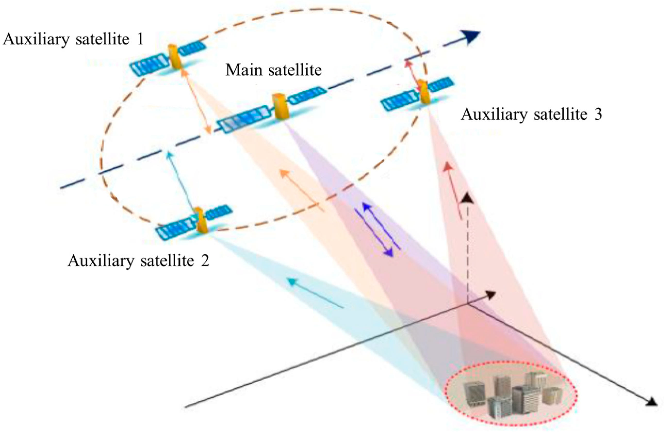
On 30 March 2023, the PIESAT-01 constellation was launched from the Taiyuan Satellite Launch Center and successfully entered the designated orbit. This satellite system is the world’s first multi-satellite distributed interferometric radar satellite system adopting a “Cartwheel” formation. The “Cartwheel” formation is a unique satellite constellation configuration where slight differences in the eccentricity of each satellite’s orbit ensure that at any given fixed moment, the main satellite remains at the center of the formation with three auxiliary satellites evenly spaced at 120-degree intervals around it. As shown in
Figure 1, the PIESAT-01 constellation maintains a coplanar configuration of its four satellites at all times through precise orbit control. The main satellite is in the center of the formation, and the three auxiliary satellites orbit the main satellite in the same elliptical trajectory. The main satellite sends detection signals to the ground, and the PIESAT-01 SAR satellite constellation receives the echo signals synchronously. Four satellites fly in a 528 km sun-synchronous orbit with a recurring cycle of 15 days and an inclination angle of 97.552°.
The primary mission of the PIESAT-01 constellation is to complete the global land-scale mapping task (between 82.5° north and south latitude) within two years, and it has high-precision deformation measurement capabilities. Additionally, surface deformation monitoring data with an accuracy of 3 to 5 mm per year can be obtained. It can also offer various types of remote sensing data products, providing high-precision InSAR measurement data and high-quality SAR images for industries such as surveying and mapping, seismic monitoring, land administration, disaster reduction, forestry, transportation, and water resources.
3. PIESAT-01Multiple Satellites Interferometric Imaging
The four-satellites interferometric imaging mode of the PIESAT-01 constellation is characterized by multi-satellite strip mode, with a resolution of 3 m and a swath width of 20–30 km (range direction), making it suitable for rapid and large-scale surveying tasks execution. The PIESAT-01 constellation consists of one main satellite equipped with both transmitting and receiving antennas, while the three auxiliary satellites are configured with only receiving antennas for interferometric strip imaging. The imaging process can be conceptualized as a monostatic SAR imaging of the main satellite and a bistatic SAR imaging involving three sets of main and auxiliary satellites. The imaging process is illustrated in
Figure 2.
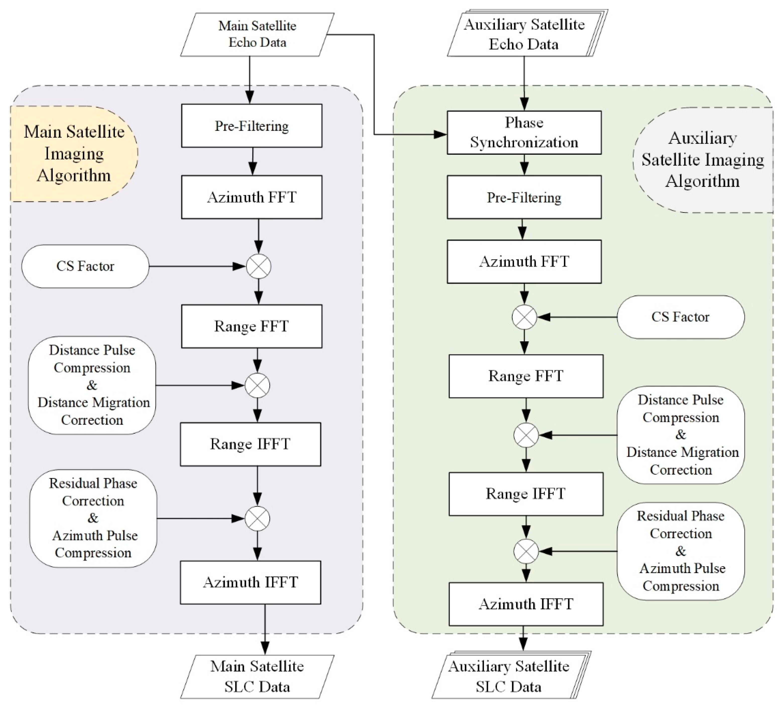
The chirp scaling (CS) algorithm [
26] was used for the main satellite monostatic SAR imaging, which initially corrects the linear range migration along the range dimension, followed by range cell migration correction (RCMC) and range-matched filtering to achieve range compression [
27]. Subsequently, matched filtering is performed to accomplish azimuth compression, resulting in the acquisition of 2D-focused strip SAR images. To enhance the accuracy of InSAR interferometric height measurement in bistatic SAR imaging of the main and auxiliary satellites, pre-filtering is incorporated into the CS algorithm to remove non-overlapping range spectral beams. Additionally, synchronous phase extraction technology and high-coherence imaging technology are employed to ensure the accuracy of phase information.
3.1. Synchronous Data Processing
For the extraction of time synchronization and phase synchronization in bistatic distributed SAR systems, the PIESAT-01 constellation employs synchronous links to alternately transmit and receive signals between two satellites. This process involves range pulse compression, selection of direct wave signals from the high-resolution range profile (HRRP), extraction of synchronization information from the direct wave signals, and subsequent adjustment of sampling gates and compensation of echo phase errors to achieve time and phase synchronization.
3.1.1. Bistatic SAR Time Synchronization
Temporal errors are caused by system atomic clock inaccuracies and system delay errors [
28]. The time-varying component of temporal errors accumulated due to clock inaccuracies leads to the range cell migration (RCM) and defocusing of SAR images.
By extracting the peak position of the received signals after range pulse compression, the arrival time of the direct wave can be determined separately at each sensor. The time synchronization error between two receivers can be estimated as follows:
where
and
represent the peak moments of the direct waves,
denotes the clock bias between the two antennas,
signifies the time taken for the electromagnetic wave to propagate from the radar
i to the radar
j in free space, and
t0 represents the starting time of the transmission signal generated by the radar
i and the starting time of the demodulation signal generated by the radar
j.
In the context of bistatic imaging, estimated temporal error refers to the uncertainty in the synchronization between the transmission and reception of signals at two separate locations, and even millisecond-level synchronization errors can lead to significant positional errors. The estimated temporal error can be compensated for by shifting range cells or multiplying by a linear phase term of range frequency in the distance domain. After bistatic SAR time synchronization, the signal envelope model received by radar
j from radar
i is as follows:
where
represents the fast time resolution after range pulse compression.
3.1.2. Bistatic SAR Phase Synchronization
Phase error arises from clock timing error, frequency cumulative error, phase noise, and initial phase difference. The initial phase difference is the main cause of the time-invariance phase error, while the frequency cumulative error and phase noise are the main causes of the time-varying phase error. Time-invariance phase error results in phase error between different transmitter–receiver combinations, leading to defocusing of the tomographic dimension, while time-varying phase error results in azimuthal phase error and, consequently, azimuthal defocusing [
29]. Therefore, it is necessary to estimate and compensate for the phase error in distributed SAR systems.
Similar to time synchronization, the phase of the direct wave signal peak after distance pulse compression extraction can be used to obtain the phase of the bi-directional direct wave. Subsequently, the phase error between the two receivers can be estimated as follows:
The estimated bistatic phase error can be compensated. Upon bistatic phase synchronization, the phase of the signal transmitted from radar
i and received by radar
j is as follows:
From this, it can be inferred that the time-varying phase error has been compensated, implying that if the involved time errors are not significant, the bistatic 2D imaging can be effectively focused.
3.2. High Fidelity Phase Imaging
To address the reduced coherence between main and auxiliary images and the interference phase error caused by Doppler spectrum shift along the along-track baseline, a pre-imaging procedure is implemented. Initially, the overlapping Doppler spectra are identified based on the center frequency and Doppler bandwidth of the main and auxiliary satellite echo data. Subsequently, the non-overlapping portion of the Doppler spectrum is filtered out prior to imaging.
Unlike monostatic SAR, the slant range trajectory between the bistatic strip SAR satellite and the target follows a bi-square root form, which can be expressed using Taylor expansion as follows:
Furthermore, the bistatic strip SAR signal model can be represented as follows:
where
σ represents the target’s backscattering coefficient,
c denotes the speed of light,
λ signifies the signal wavelength,
and
denote the temporal distance envelope and azimuth envelope of the signal, respectively,
represents the range-time, and
denotes the signal frequency modulation.
Perform azimuth Fourier transform on the received signal, followed by multiplication with the following variable standard equation:
The purpose of this step is to correct residual range cell migration (RCM), followed by performing range Fourier transform and subsequently conducting range pulse compression and range migration correction, namely, multiplication with
After performing the inverse range Fourier transform, azimuth compression is then conducted, with the azimuth-matched filter being applied:
Upon performing the inverse azimuth Fourier transform, the focused 2D SAR image is obtained.
4. PIESAT-01 Digital Surface Model (DSM) Production Techniques
The InSAR technique is a technology that utilizes interferometric phase information to process two SAR single-look complex images of the same area, generating digital surface model (DSM) data [
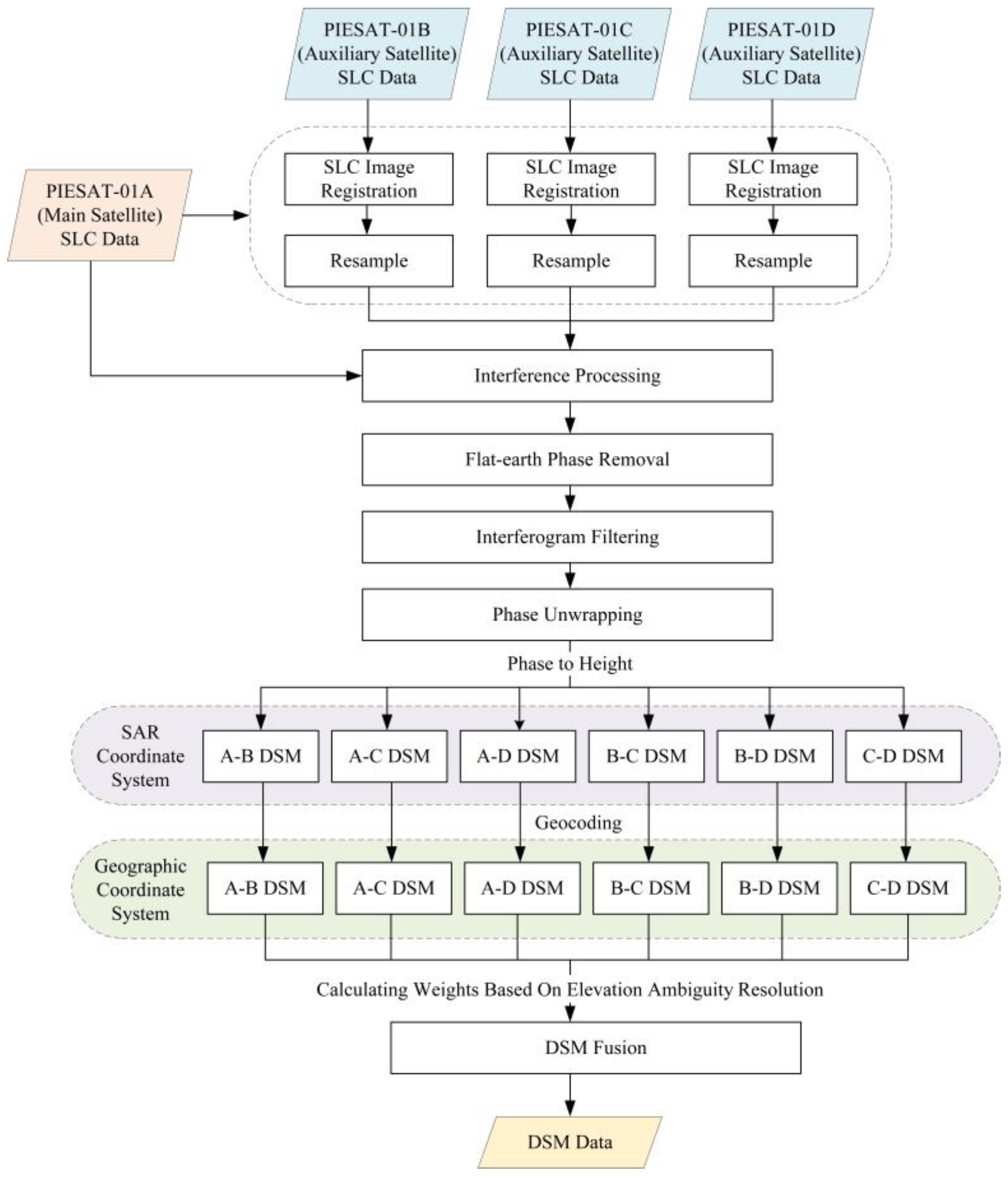
30]. The interferometric phase consists of the deformation phase, atmospheric delay error phase, topographic phase, orbit error phase, and noise phase. To obtain high-precision topographic phase results, effective estimation and elimination of the other components are necessary. Since the PIESAT-01 constellation can capture four sets of images of the same area in one imaging session, there is no deformation phase or atmospheric delay error phase caused by different acquisition times during the InSAR processing. The data exhibit extremely high coherence, which can significantly enhance the accuracy of DSM from the source. The DSM acquisition process of PIESAT-01 is illustrated in
Figure 3, including coregistration of master and slave images, interferogram generation, flat-earth phase removal, interferogram filtering, phase unwrapping, raw DSM generation, and DSM fusion.
The complex images coregistration is the first step in interferometric processing. Due to the incomplete overlap of satellite orbits and slight differences in the incident angles of satellite antennas, there are certain degrees of translation, rotation, and stretching in the corresponding pixel positions of the multiple SAR images used for coherent processing. To improve the coherence between SAR images, it is necessary to perform coregistration and resampling operations on SAR images to ensure that the same pixel points in SAR images obtained from different baselines correspond to the same target points on the ground. The coregistration accuracy of the two images should be better than 0.2 pixels to achieve the correct interferometric phase information between image pairs.
The second step involves interferogram generation. The coregistered master and slave SAR images are conjugately multiplied, and their phase is extracted to obtain the interferogram. The interferometric phase reflects the slant range difference between the antennas of the master and slave satellites to the imaging scene. Due to the periodic nature of trigonometric functions, the interferometric phase is wrapped within the interval of (−π, π]. The coherence coefficient is a key parameter used in interferometric SAR processing to assess the coregistration accuracy between the master and slave SAR images and the quality of the interferometric phase. The expression for calculating the coherence coefficient is as follows:
where
and
represent the master and slave SAR images, respectively. A higher value of the coherence coefficient
γ indicates a higher quality of the interferometric phase, which is more beneficial for subsequent interferometric processing.
In the interferometric phase, the relationship between the signal-to-noise ratio and coherence coefficient is as follows:
indicating that as the coherence coefficient increases, the signal-to-noise ratio of the interferometric phase also increases, leading to a higher-quality interferometric phase.
Due to the presence of a flat-earth phase, the interferometric phase generated through the aforementioned steps exhibits regular stripe variations in the range direction, resulting in excessive phase wrapping and overly dense stripes in the interferometric phase map, significantly impacting the accuracy of phase unwrapping. To reduce the density of interferometric stripes and alleviate the difficulty of phase filtering and unwrapping, this paper eliminates the flat-earth phase, retaining only the height phase reflecting topographic changes in the imaging scene. Additionally, adaptive filtering is employed for phase denoising to remove residual points caused by spatial decorrelation noise between the master and slave SAR images and system thermal noise.
Phase unwrapping is a crucial step in obtaining high-precision terrain elevation information in InSAR imaging, and the unwrapped interferometric phase directly affects the accuracy of terrain elevation extraction. In this paper, the minimum cost flow algorithm is used for phase unwrapping. By utilizing the unwrapped phase, radar system parameters, and the geometric relationships in InSAR, height information for each pixel in the image can be calculated based on elevation conversion formulas. Through terrain correction, the DSM can be reconstructed using InSAR data processing.
Finally, using the multi-baseline DSM data fusion technique compensates for low coherence, shadowing, and high-error areas, enhancing the accuracy of the DSM [
31]. The weights commonly used in traditional weighted averaging methods are mostly based on the ratio of coherence coefficients or vertical baselines [
32]. In this paper, theoretical height errors corresponding to interferometric phases of different baselines are utilized to achieve the fusion of multi-baseline DSMs. The weights are determined based on the statistical characteristics of the probability distribution of interferometric phases, taking into account the height error determined by jointly considering various InSAR geometric parameters such as incidence angle, vertical baseline, slant range, etc., involved in different interferometric combinations, making this approach more rational.
Assuming a multi-baseline spaceborne InSAR system acquires
n sets of interferometric phases, according to the conversion formula between interferometric phase and elevation, where any unwrapped interferometric phase and theoretical terrain elevation satisfy the following equation:
where
represents the
ith set of interferometric phases,
h denotes terrain elevation information,
λ represents wavelength,
is the slant range of the
ith interferometric pair,
θ stands for the incidence angle of the
ith interferometric pair, and
represents the vertical baseline length of the
ith interferometric pair.
Elevation ambiguity resolution, as an important evaluation metric in InSAR imaging technology, has a certain reference value for assessing the performance of multi-baseline InSAR height estimation. In theory, elevation ambiguity resolution can be utilized to invert the height phase into terrain elevation. After obtaining the standard deviation of phase noise, elevation ambiguity can be used to approximate the DSM theoretical error. The elevation ambiguity resolution corresponding to different baseline lengths in multi-baseline InSAR is as follows:
The standard deviation of height estimation
caused by the estimation error
of the
ith (
i = 1,…, N) observed interferometric phase is calculated as follows:
Weight
is constructed using the height errors
corresponding to different baselines according to the following:
Finally, the weights constructed from the height error of each interferometric phase group are used to perform weighted fusion on the terrain elevation information
h obtained from single-baseline interferometric processing of the
ith group, as follows:
For quantitative evaluation of DSM accuracy, mean error (ME) and root mean square error (RMSE) are commonly used. In this paper, ICESat-2 global geolocated photon data are utilized as external control points for validation. The calculation formulas are as follows:
where
M and
N represent the rows and columns of the DSM, respectively,
denotes the elevation calculated from InSAR imaging processing, and
represents the actual terrain elevation.
5. Results and Analysis
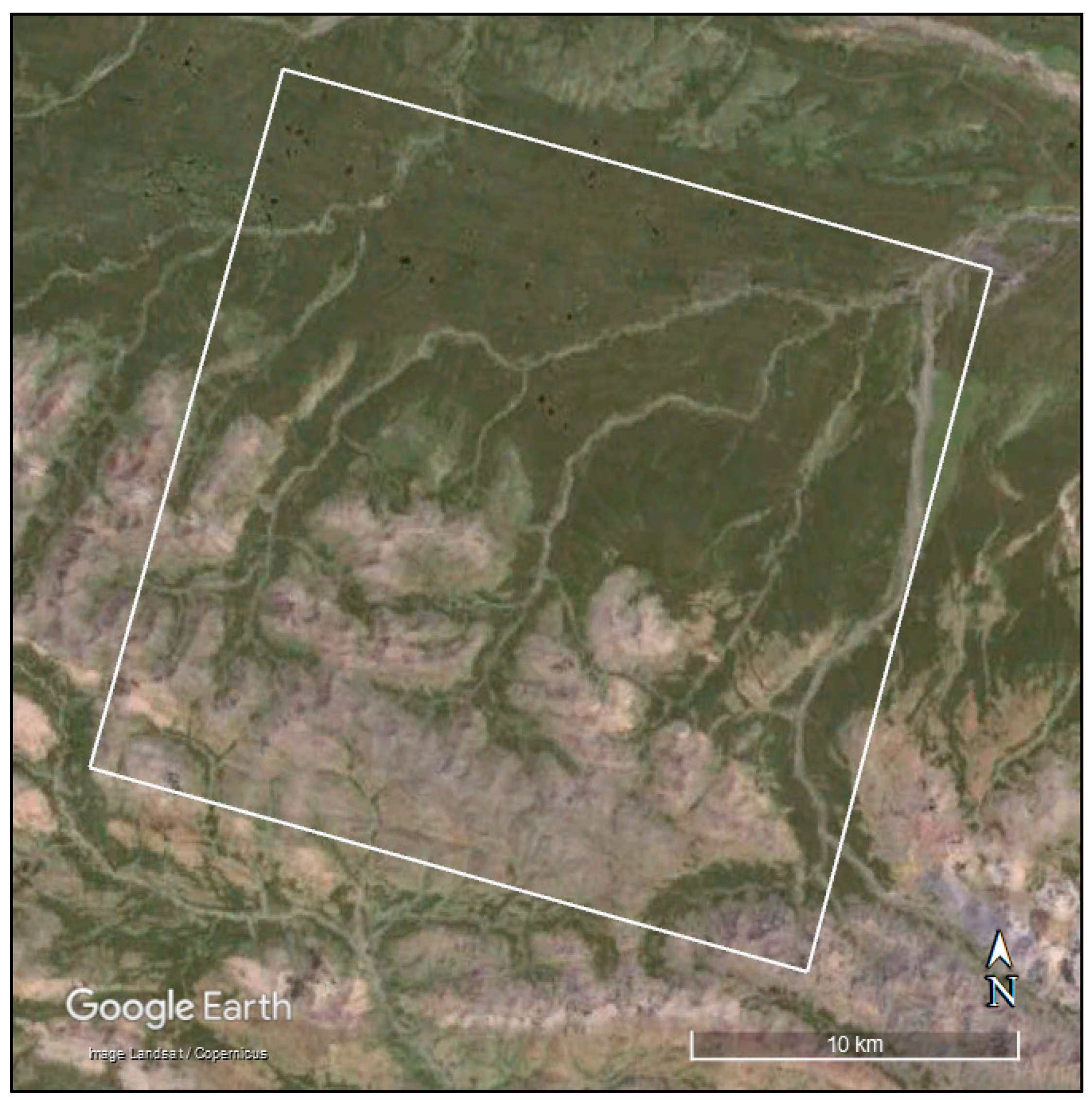
The selected region in Qinghai Province, China, was imaged using a four-satellite interferometric imaging mode, with PIESAT-01A as the master satellite and PIESAT-01B, PIESAT-01C, and PIESAT-01D as auxiliary satellites.
Figure 4 is the optical imagery of the Qinghai research area on Google Earth. This location was chosen as the research area because it includes both mountainous and flat terrains, allowing for a clear evaluation of the adaptability and accuracy of the imaging and DSM algorithms under varying topographical conditions. The observation is conducted with a descending orbit left-looking configuration at an observation angle of 43.853°. After decompressing the original echoes, the data were processed using the bistatic interferometric CS imaging algorithm.
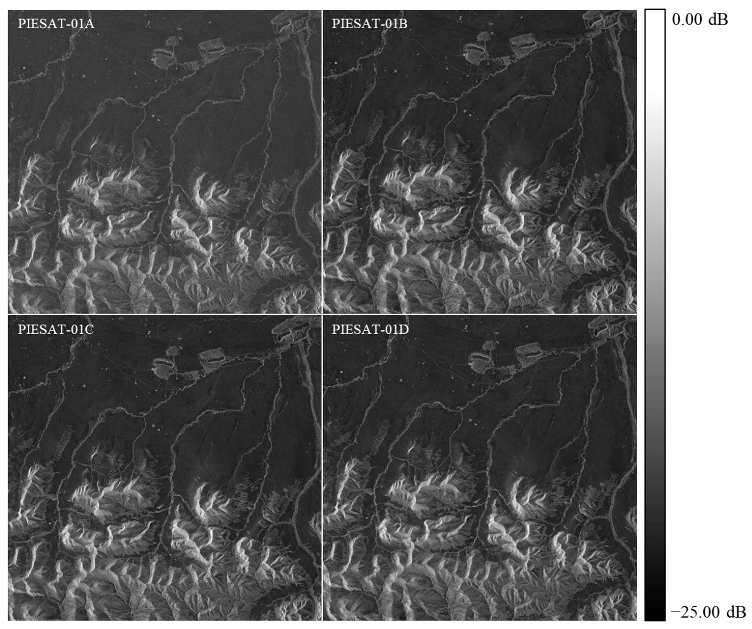
Figure 5 presents the imaging results of the selected region using the PIESAT-01 constellation.
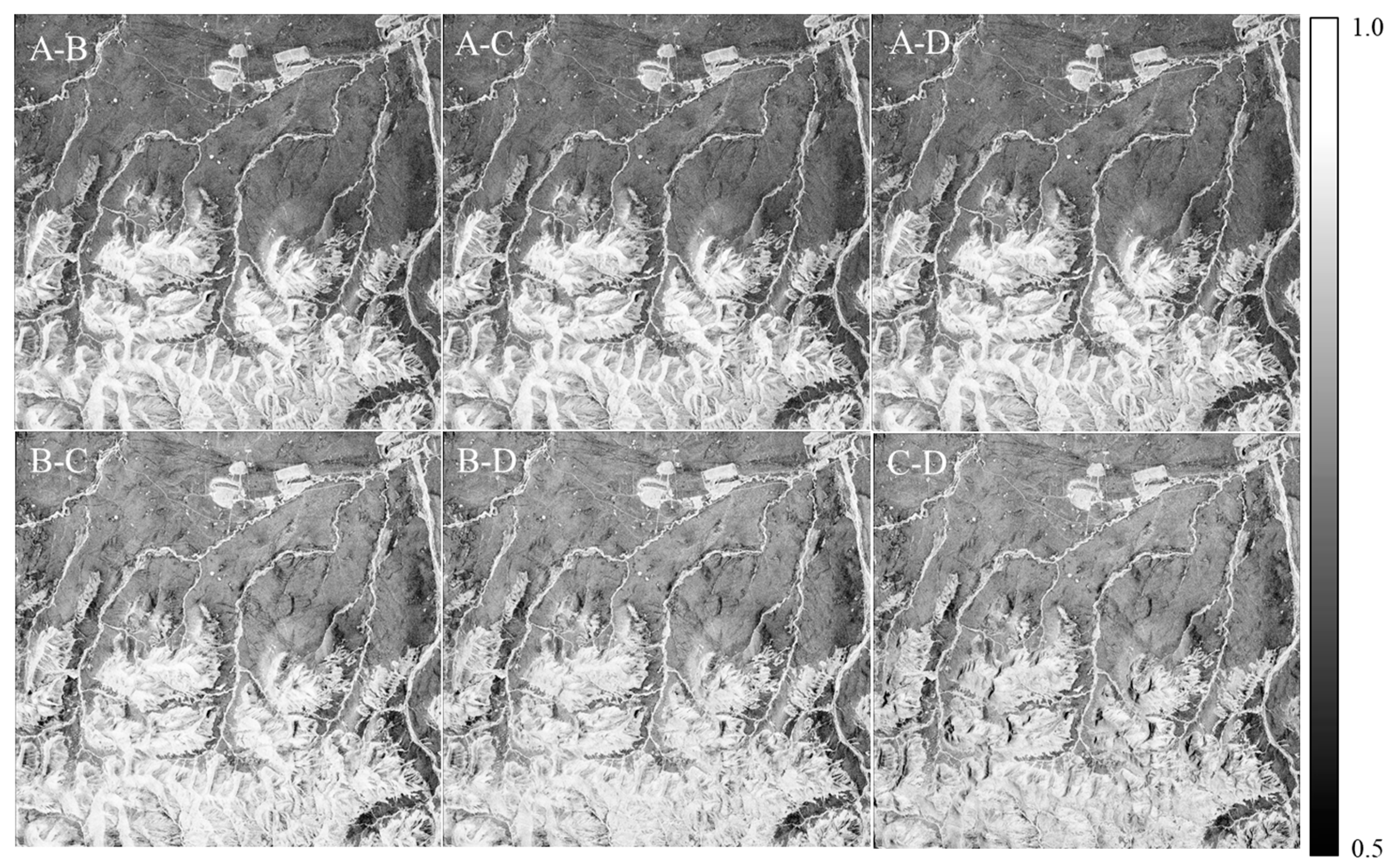
Interferometric processing is conducted on the imaged data. Initially, the complex SAR images are cropped and registered. The registration accuracies in the range direction after registration of A-B, A-C, and A-D pairs are 0.012, 0.045, and 0.031 pixels, respectively, while in the azimuth direction, the registration accuracies are 0.021, 0.056, and 0.014 pixels, respectively, meeting the requirements for interferometric processing. Coherence is a critical factor influencing terrain extraction.
Figure 6 depicts the coherence map after regional registration. Statistical analysis reveals that the mean coherence values between each pair of images exceed 0.8, indicating excellent coherence of SAR images under the four-satellite interferometric imaging mode.
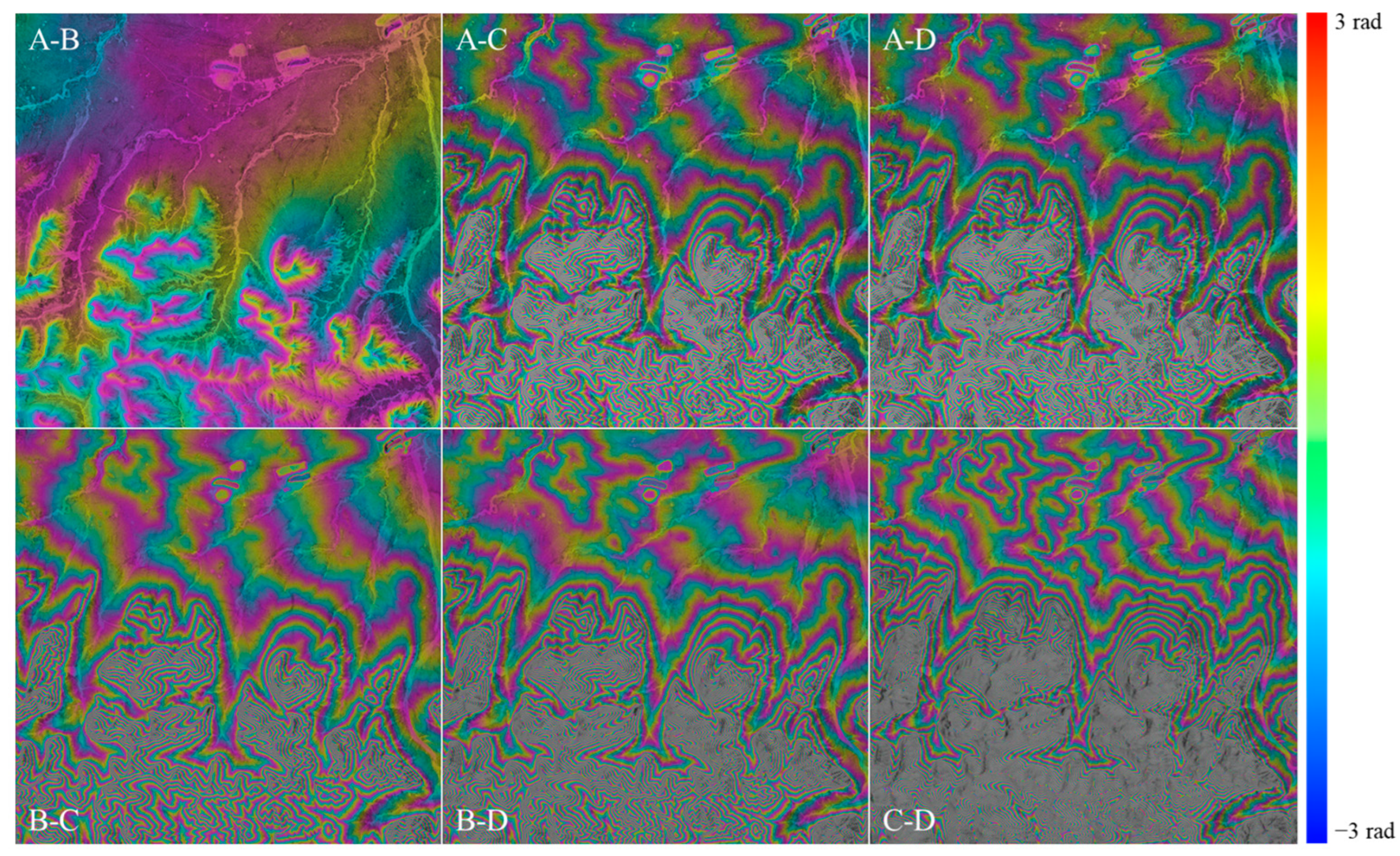
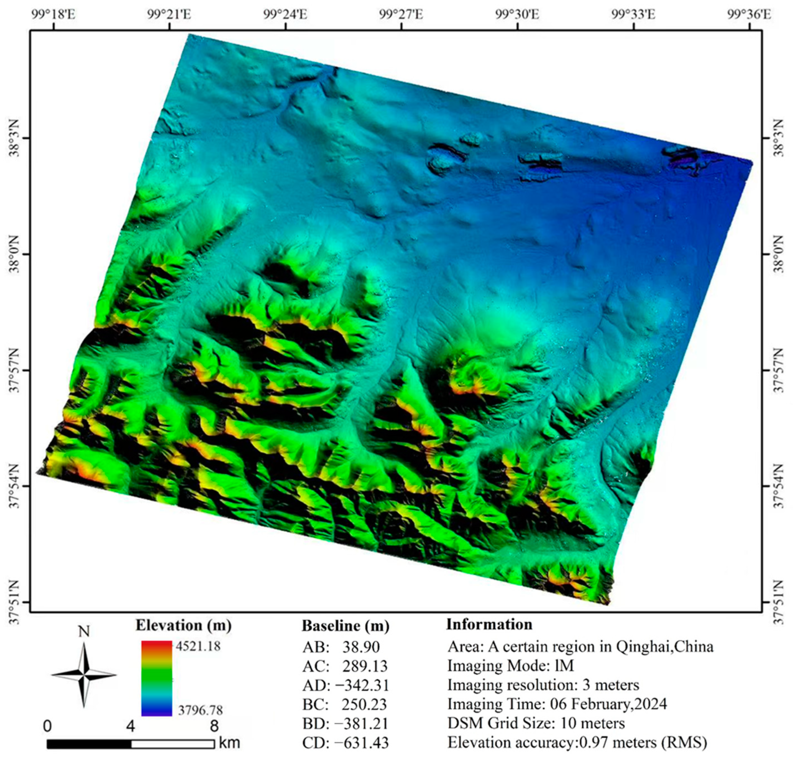
Interferometric processing was conducted on the registered data to remove the flat phase, resulting in the phase changes induced by the topographic elevation variations, as depicted in
Figure 7. The baselines corresponding to the A-B, A-C, A-D, B-C, B-D, and C-D paired data were measured as 38.90 m, 289.13 m, 342.31 m, 250.23 m, 381.21 m, and 631.43 m, respectively.
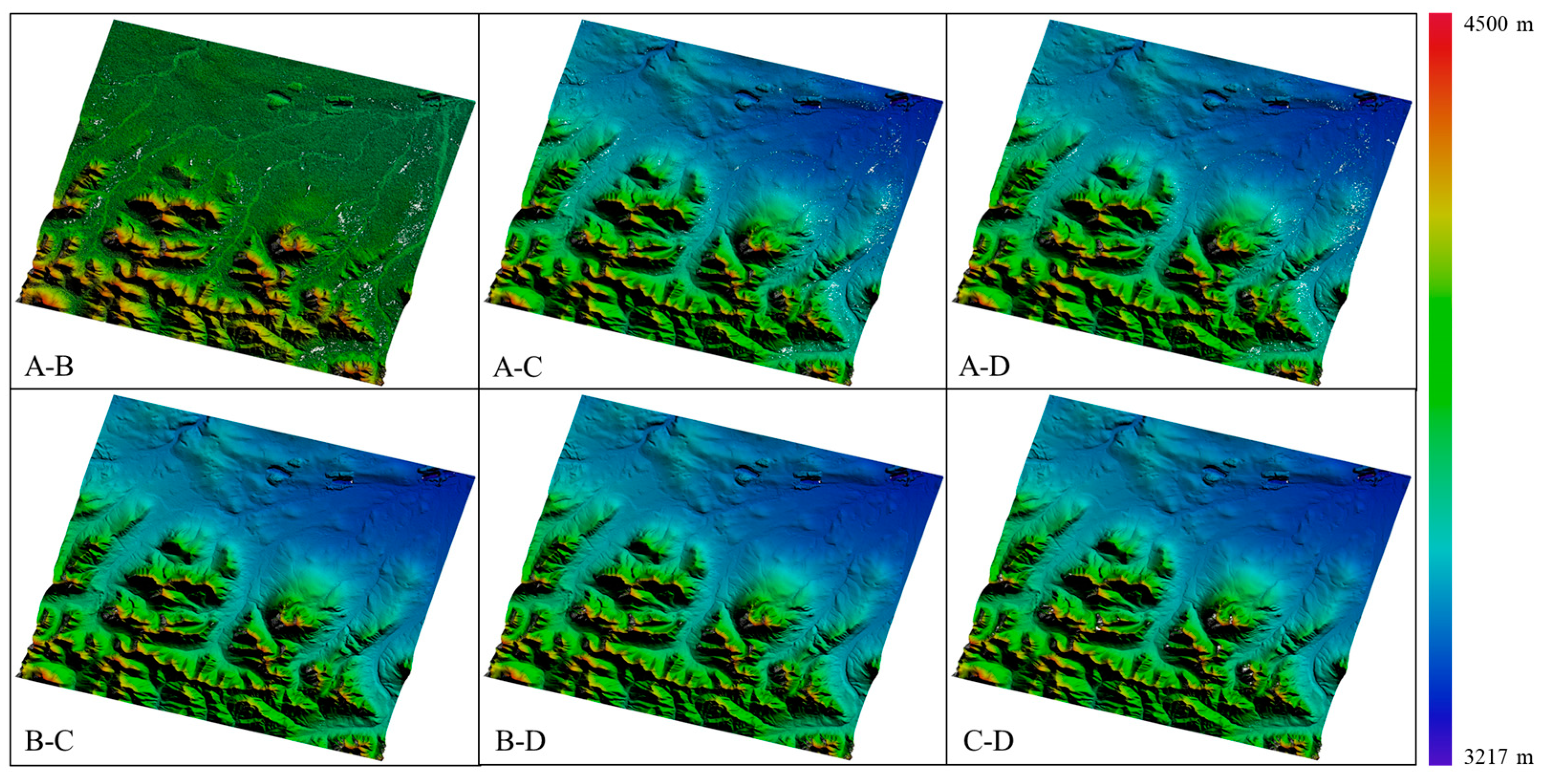
Subsequently, the phase unwrapping of the filtered and flat-corrected phases was performed using the minimum cost flow (MCF) method to obtain the unwrapped phase results. Following 3D positioning, refined baselines were utilized to generate a DSM, which was then geocoded to obtain the geographically referenced RAW DSM, as depicted in
Figure 8.
Figure 9 presents the fused RAW DSM product utilizing elevation ambiguity. The fused DSM effectively fills the voids in shadowed and overlapping areas, resulting in a notable enhancement in DSM quality.
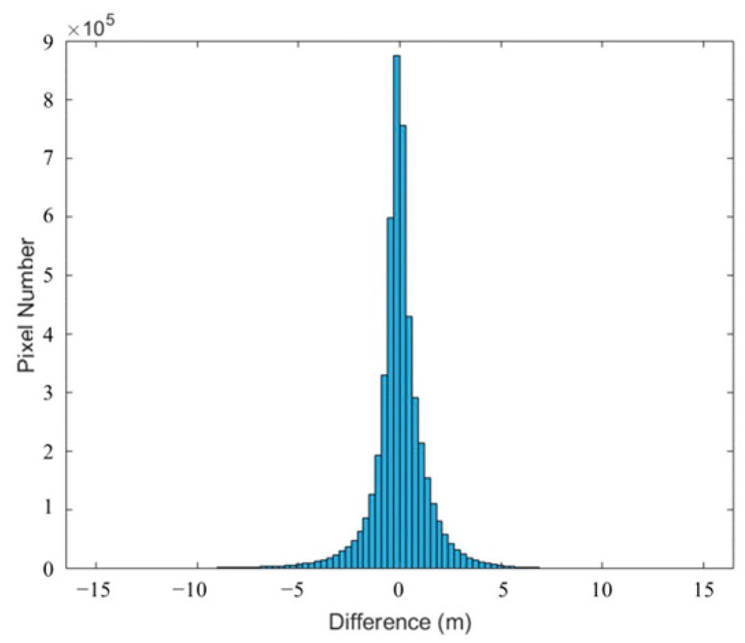
Finally, the accuracy of the DSM was validated by comparing it with ICESat-2 global geolocated photon data and TanDEM DSM data. There were a total of 1030 ICESat-2 checkpoints on the imagery, with a 0.06 m ME and a 0.96 m RMSE for the altimetry points. Additionally, a histogram of the differences between the PIESAT-01 DSM and the TanDEM DSM, as shown in
Figure 10, confirmed the phase coherence of the imaging algorithm and the interferometric measurement and 3D reconstruction capabilities of the data.
To further validate the imaging performance and DSM product quality in various terrain scenarios, three areas with distinct terrains were selected for DSM generation and accuracy assessment.
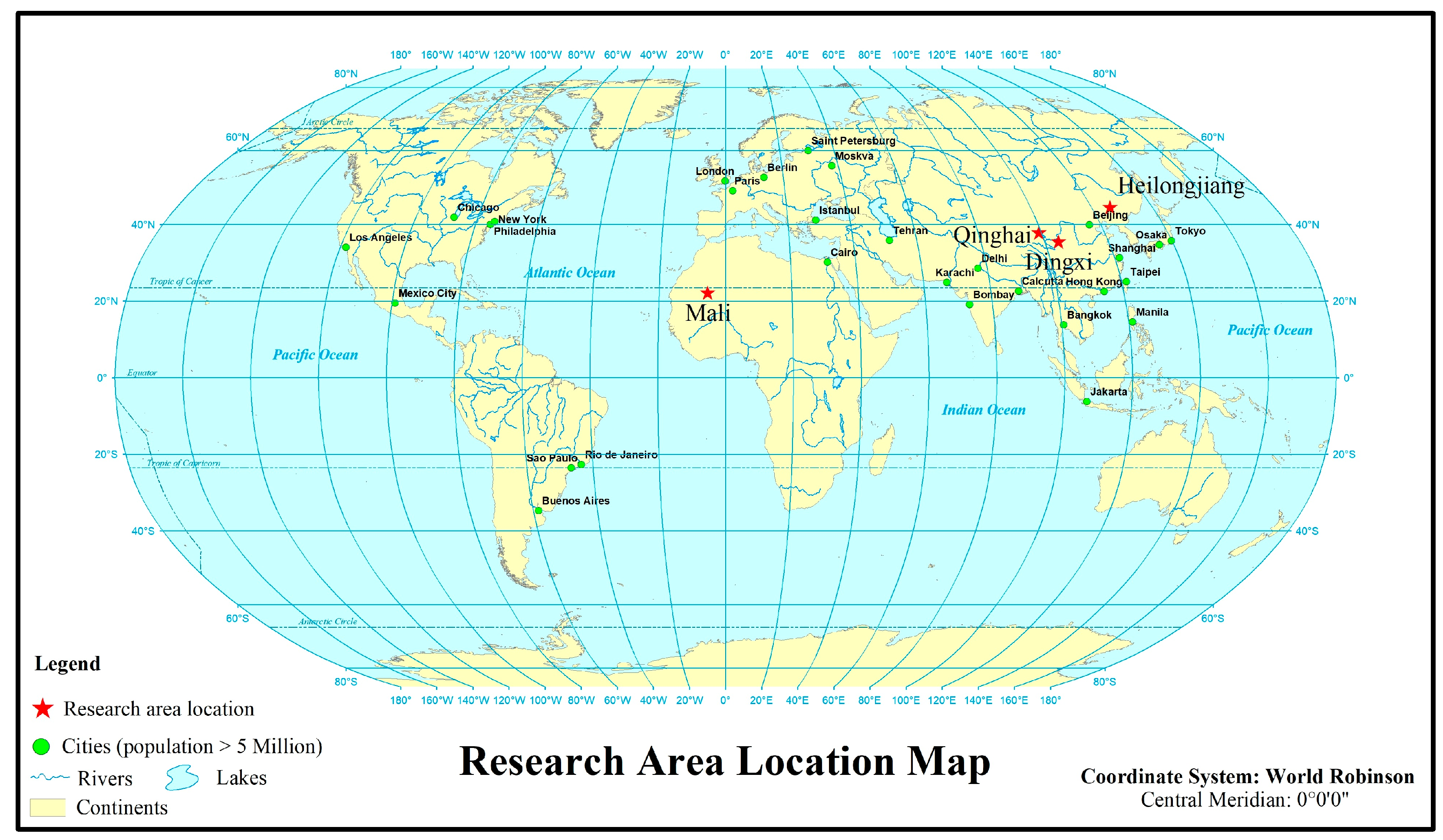
Figure 11 shows the location of the selected research area.
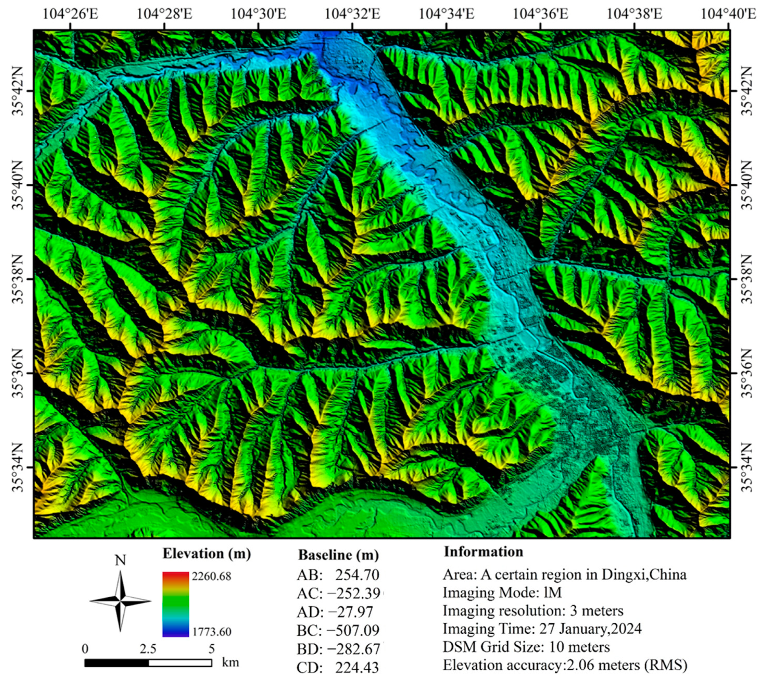
Dingxi is located in the northwestern region of China and is characterized by typical mountainous terrain.
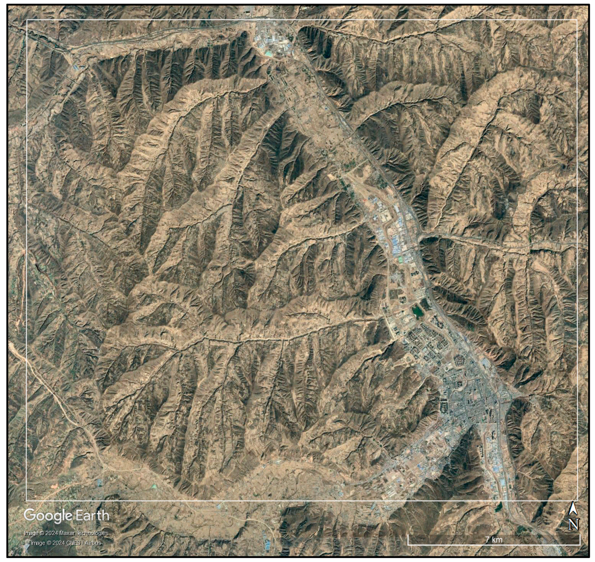
Figure 12 is the optical imagery of the Qinghai research area on Google Earth. Complex mountainous regions are the best areas for testing the advantages of multi-baseline DSM production. Fewer baselines often result in areas with numerous phase unwrapping errors, which are then masked out, leading to discontinuities in the DSM results. Therefore, we selected this area to validate the interferometric capabilities of the PIESAT-01 constellation in mountainous regions.
Figure 13 shows the RAW DSM of a specific area in Dingxi generated based on PIESAT-01 data. The texture of the mountainous area is clear, and rivers are distinctly visible, with no discontinuities caused by phase unwrapping errors due to phase jumps. This effectively demonstrates the fine details in the data.
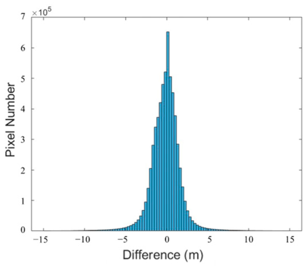
A total of 28 ICESat-2 checkpoints were identified on the imagery, with a 0.47 m ME and a 2.06 m RMSE for the altimetry points. Additionally, a histogram of the differences between the PIESAT-01 DSM and the TanDEM DSM is illustrated in
Figure 14.
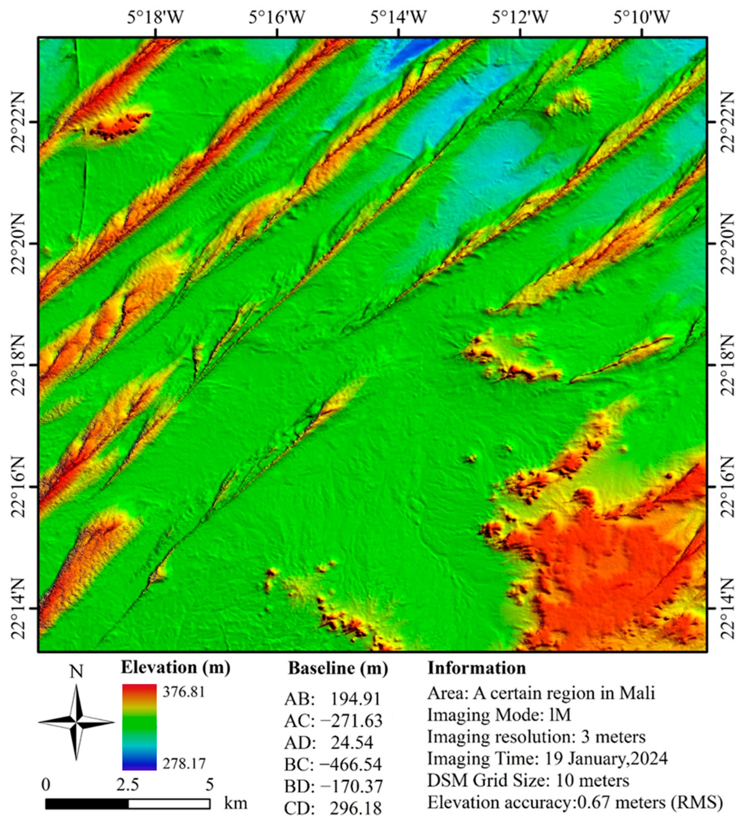
Mali, situated in the central-western region of West Africa, features the Sahara Desert in its northern part.
Figure 15 is the optical imagery of the Mali research area on Google Earth. Desert regions are ideal for testing imaging and registration algorithms. Incorrect imaging can lead to registration failures, thereby preventing DSM production. Therefore, we have chosen desert areas as another validation zone.
Figure 16 depicts the RAW DSM of the desert region in Mali generated based on PIESAT-01 data, illustrating clear textures and orientations of sand dunes.
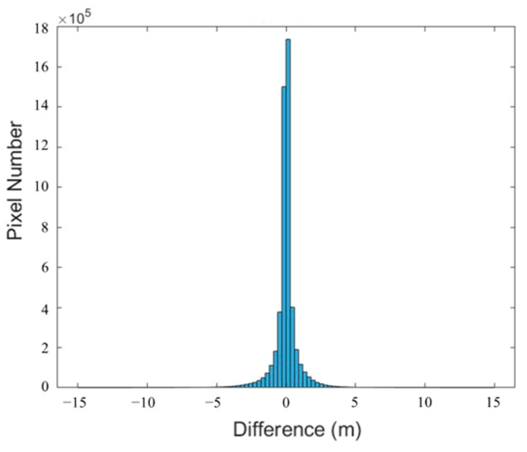
A total of 1555 ICESat-2 checkpoints were identified on the imagery, with a mean error of 0.27 m and a standard deviation of 0.67 m for the altimetry points. Additionally, a histogram illustrating the differences between the PIESAT-01 DSM and the TanDEM DSM is shown in
Figure 17.
Heilongjiang Province is located in the northeastern part of China, mainly consisting of mountains, plateaus, and plains.
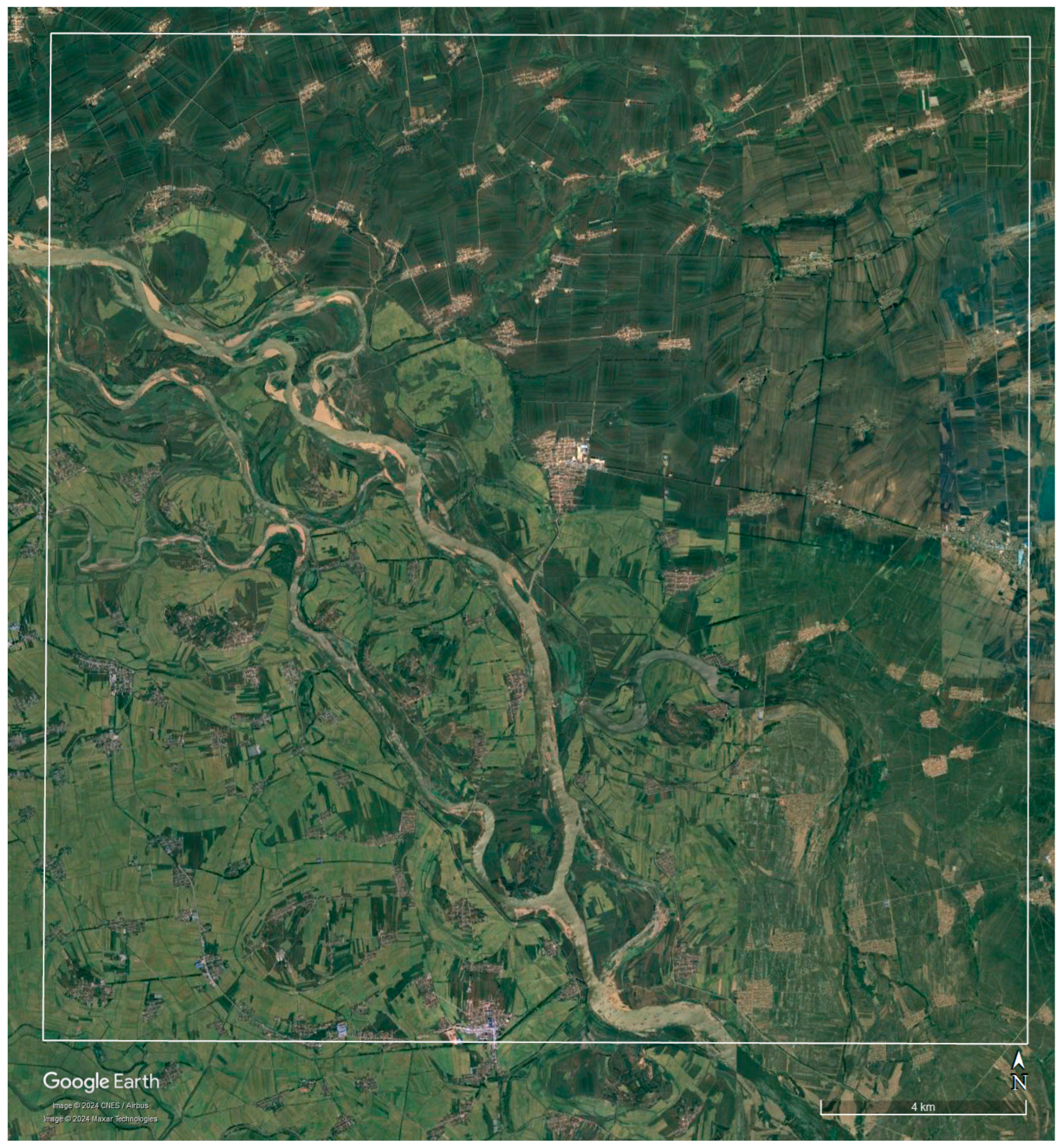
Figure 18 is the optical imagery of the Heilongjiang Province research area on Google Earth. Plain areas are ideal for showcasing DSM details; therefore, we have selected this region to examine the detail resolution of DSM products.
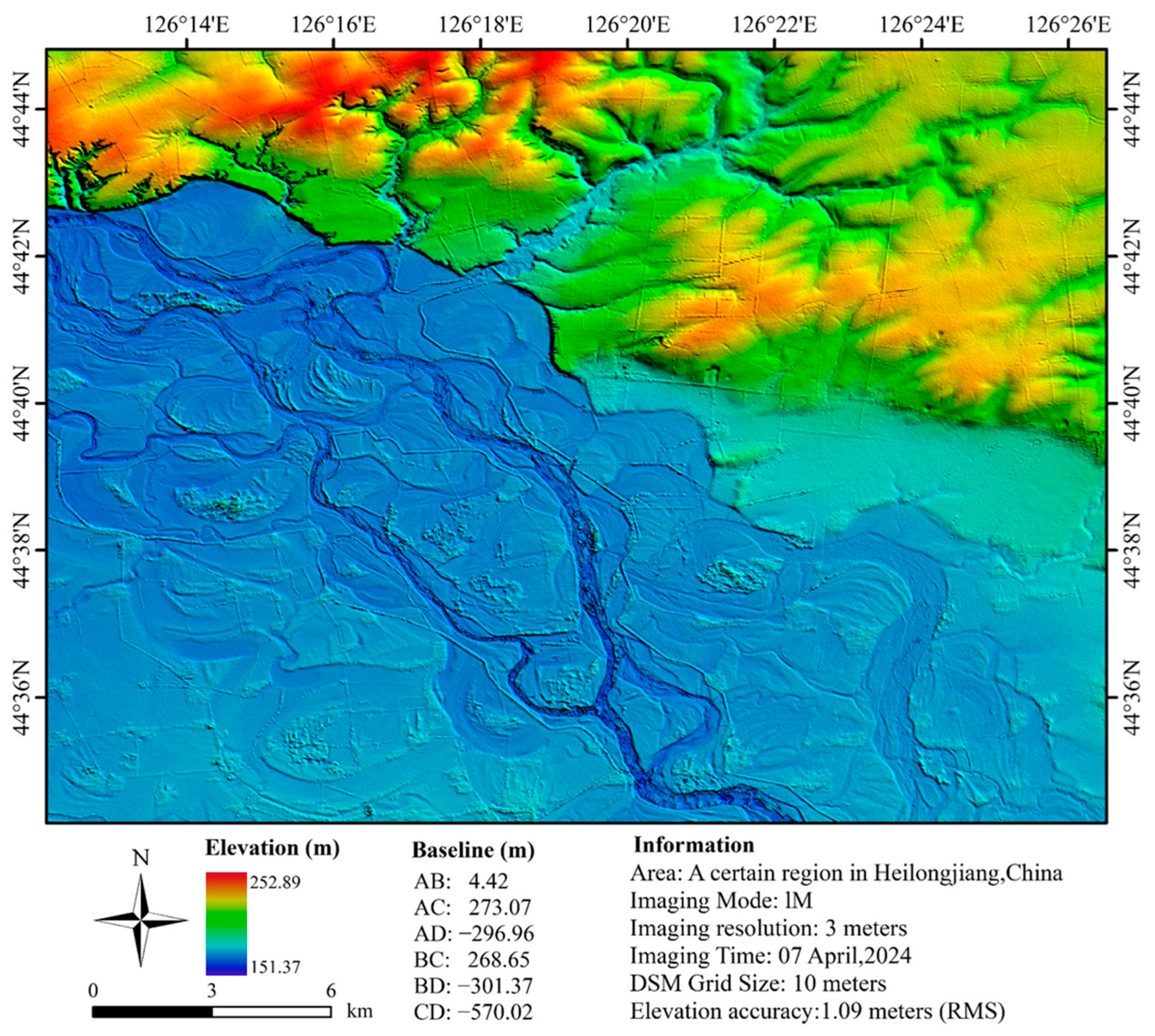
Figure 19 shows the RAW DSM of the eastern plain area of Heilongjiang Province generated based on PIESAT-01 data. The distribution of farmland, embankments, and rivers is clearly visible in the figure, demonstrating the high definition and detailed reproduction capability of the PIESAT-01 DSM.
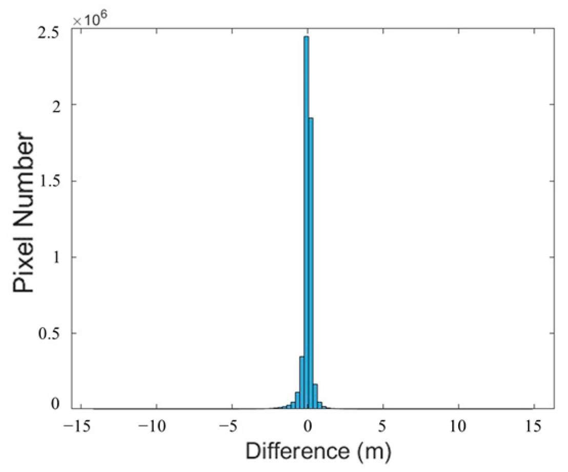
A total of 2097 ICESat-2 checkpoints were identified on the imagery, with a 0.62 m ME and a 1.09 m RSME for the altimetry points. Additionally, a histogram illustrating the differences between the PIESAT-01 DSM and the TanDEM DSM is shown in
Figure 20.
Through validation in typical mountainous, desert, and plain areas, it is evident that the DSM exhibits clear details and sharp textures. Verified by ICESat-2 global geolocated photon data and TanDEM data, the DSM demonstrates high accuracy, meeting quality requirements such as 1:50,000 scale or HRTI-3, thereby providing effective data support for various industrial applications and scientific research endeavors.
6. Discussion
The concept of formation flying satellites has been introduced for many years [
33,
34,
35], and the utilization of multi-baseline methods to enhance the accuracy of DSM is regarded as one of the most promising approaches. Bistatic SAR imaging methods and multi-baseline DSM processing techniques have also been the focus of research in recent years. However, studies typically utilize simulated data, repeat-pass data, or data from two formation-flying satellites for investigation. The PIESAT-01 satellite, as the world’s first four-satellite formation flying mission, exhibits superior imaging quality, and its interferometric results meet the accuracy requirements of China’s 1:50,000 scale requirement. The data from the PIESAT-01 satellite can provide high-quality data for multi-baseline SAR imaging and application research.
This paper employs the bistatic imaging CS algorithm, which also finds widespread application in the 3D algorithm of multi-baseline SAR imaging and holds considerable potential for further development [
36,
37]. However, with the advancement of multi-baseline interferometric SAR technology, the demand for scene 3D imaging extends beyond merely extracting surface elevation information from DSM. Instead, there is a shift towards achieving true 3D SAR imaging of scenes from the perspective of resolution. In this context, multi-baseline interferometric SAR imaging systems typically project the scattering characteristics of 3D target scenes onto the 2D range-azimuth plane, treating the resulting sequence of 2D images as echo data in the height direction, followed by height direction focusing, which has been a recent research focus. PIESAT-01, as a dataset with simultaneous multi-baseline observations, can provide high-precision and effective data for such studies.
Moreover, the DSM processing method proposed in this paper involves multi-baseline DSM fusion. For complex terrains containing steep slopes or discontinuous surfaces (e.g., numerous buildings, canyons, and steep mountains), severe undersampling phase phenomena may occur, where adjacent phase differences in interferograms can exceed π. In such cases, multi-baseline phase unwrapping techniques are considered effective means to overcome the limitations of the phase continuity assumption and generate absolute phases for complex terrains [
38,
39]. Their potential advantage lies in leveraging multiple interferograms corresponding to different baseline lengths, thereby circumventing the strict constraint of adjacent phase differences not exceeding π. Commonly used multi-baseline unwrapping algorithms include coarse-to-fine phase unwrapping and maximum likelihood phase unwrapping.
Lastly, it is meaningful to analyze error interference terms in the processing of multi-baseline InSAR data, as this can be an effective method to further enhance the computational accuracy of DSM. For instance, studying the impact of the atmospheric phase on interferometric phase and elevation accuracy is one such avenue. By utilizing real-time DSM and DEM data, it becomes possible to more effectively eliminate terrain phases and obtain more accurate deformation results.

