Article

Design and Simulation of Aerosol Inlet System for Particulate Matter with a Wide Size Range

1
Institute of Mass Spectrometry and Atmospheric Environment, Jinan University, Guangzhou 510632, China
2
Guangzhou Hexin Instrument Co., Ltd., Guangzhou 510700, China
*
Author to whom correspondence should be addressed.
Atmosphere 2023, 14(4), 664; https://doi.org/10.3390/atmos14040664
Submission received: 16 February 2023 / Revised: 22 March 2023 / Accepted: 29 March 2023 / Published: 31 March 2023
(This article belongs to the Section Atmospheric Techniques, Instruments, and Modeling)

Abstract

:
A novel aerodynamic lens-based inlet system was developed for a wide particle size range, and it could extend the size range of transmitted particulate matter (PM) to 50 nm–10 μm. The lens system adopted a seven-stage aerodynamic focusing orifice to extend the range of transmitted PM, and a relaxation system with a virtual impact function was introduced at the front of the aerodynamic lens. Through the innovative design, the system could concentrate the input samples as well as effectively enhance the focusing effect on large PM. Furthermore, an additional aerodynamic pre-focusing inlet system was innovatively added to the front of the sampling orifice of the traditional aerodynamic lens, and it could pre-focus large PM into the axis region before it entered the small orifice and then solve the previous problem with loss of large PM. Fluid simulations indicated that the inlet system could achieve 100% effective transmission and focusing for PM in the range of 0.18–10 μm. The characterization and verification results obtained from the improved single-particle aerosol mass spectrometer (SPAMS) were remarkably consistent with the theoretical values. The practical tests indicated that bioaerosol particles up to 10 μm could be detected. Compared with the observation for the same type of lens, the focusing performance of this novel lens system has better advantages in particle size range and transmission efficiency and therefore, it has broad application prospects in bioaerosol research, single-cell analysis, etc.

1. Introduction

Effective focusing on particle beams is a crucial prerequisite for realizing highly sensitive detection of an aerosol mass spectrometer [1,2,3]. In the 1990s, Liu et al. reported an aerodynamic lens (A-lens)-based particle beam sampling technology, which focused an aerosol step by step through a combination of multi-stage orifices [4,5]. The technology has various advantages: a wide size range of focused particles, a small divergence of the particle beam, a low flow rate, etc. At present, almost all aerosol mass spectrometers use A-lens as their sampling device [1,2,3,6,7,8]. Although the particle size range and transmission efficiency of A-lens have been considerably enhanced compared with those of the capillary technology and nozzle technology [9,10,11], the effective focusing size range of the present A-lens is generally only within one order of magnitude [2,8,12,13,14,15,16], such as 50–500 nm and 100–3000 nm. Due to the insufficient focusing capability of A-lens, the detection of large PM such as spores, pollen, and single-cells based on aerosol mass spectrometry is still challenging [17,18,19,20,21]. This is because larger particles have higher inertia, due to which a beam of large PM diverges; also, it cannot be focused when the inertia is considerably higher than the gas drag force [5,19]. Additionally, the small PM will either be out of focus with the diffusion of airflow or be difficult to focus effectively due to Brownian motion [22,23,24].
For an aerodynamic lens system with an identical design, focusing PM in a wider size range has always been an important content of research [24]. The study reported by Wang et al. [22,23] indicated that a carrier gas with low density is conducive to focusing small PM, and some critical orifices with special structures can also effectively reduce the backflow deposition of small PM, thereby decreasing the sampling loss of small PM. In addition, the pressure at the front end of the lens also affects the focusing effect on PM. For a lens with constant physical dimensions, the smaller the pressure at the front end, the better the transmission of small PM. For enhancing the focusing capability for large PM, a basic design idea is to increase the series of aerodynamic lenses. Since the focusing of PM by aerodynamic lenses is carried out step by step, theoretically, a wider range can be achieved by increasing the number of lenses. Schreiner [13,25] adopted a multi-stage lens system with a higher sampling pressure and found that it effectively enhanced the focusing ability for large PM, which was consistent with the principle that increasing the flow rate entering the lens can enhance the focusing effect on large PM. Li et al. [26] found that the introduction of a pre-concentration inlet system at the front of an aerodynamic lens can not only play a significant role in concentrating PM but also effectively enhance the transmission efficiency of large PM. A set of seven-stage aerodynamic lenses designed by Cahill [19] also combined a virtual impact system for particle concentration at the front of the lens to achieve effective focused transmission of 4–10 μm PM. However, the transmission efficiency of PM larger than 6 μm dropped sharply in actual tests, which was quite different from the theoretical prediction. Gard et al. [27] published in a patent a structure similar to that reported by Cahill et al. and claimed that it can focus PM with a size range of 1–10 μm, but no accurate application data were reported. Based on numerical software, Lee et al. designed a set of aerodynamic lens inlet systems suitable for a wide range of 30 nm–10 μm [28]. The lens system uses a combination of a seven-stage aerodynamic lens and a focusing orifice that expands first and then contracts. Theoretically, it can enhance the transmission efficiency of PM with a wider size range, but the loss of large PM at the critical orifice was not considered in the numerical simulation process; therefore, the transmission efficiency of large PM would be overestimated. To this end, the research group further designed a converging-diverging (C-D) orifice to solve the loss of large PM. The specially designed conic orifice can effectively reduce such a loss and achieve a transmission efficiency of more than 60% for 10 μm PM. However, the group also reported that the design of this structure is so ideal that it is very difficult to process and assemble in the actual structure. In practical processes, a major loss of large PM occurs at the front of the sampling orifice. Due to the considerably high inertia, a large part of large PM is deposited on the surface of the sampling orifice and cannot enter the instrument, resulting in its loss. To date, no effective way has been reported to eliminate the loss [29].
In this study, a seven-stage aerodynamic lens system with a virtual impact system was designed, and a pre-focusing sampling and connection technology were innovatively adopted to accomplish focused sampling on PM with a very wide size range from 50 nm to 10 μm. The numerical simulation results indicated that the entire newly designed aerodynamic lens inlet system could achieve high-efficiency transmission for 62 nm–13 μm PM. The transmission efficiency for 180 nm–10 μm PM was 100% and that for PM having a size of more than 62 nm was at least 50%. Preliminary experimental results confirmed that the transmission efficiency of the lens was consistent with the theoretical results, and the bioaerosol experiment also confirmed that the lens could detect fungal PM with a size of 10 μm in aerosols. The device designed in this study will provide a new solution for detecting coarse PM such as sea salt, sand dust, and bioaerosols.

2. Materials and Methods

2.1. Inlet Design and Simulation

Figure 1 shows a schematic diagram of the wide-range inlet system, which consists of four modules: a pre-focusing lens, a separation cone, a relaxation chamber, and a seven-stage aerodynamic lens. Figure 1b–d shows the detailed dimensional parameters of each module. The PM particles in the aerosol first passed through two pre-focusing orifices with diameters of 2.5 mm and 2.0 mm, and they were focused near the central axis under the action of airflow acceleration and particles’ inertia. Subsequently, the airflow passed through a critical orifice with a diameter of ~250 μm at a flow rate of approximately 480 mL/min, which indicated that the airflow underwent ultrasonic expansion and PM was accelerated [30]. A separation cone was located 1.6 mm downstream of the critical orifice (the diameter of the cone mouth was 1 mm, and the inner cone angle was 28°). Excess air was extracted between the critical orifice and the separation cone under the action of a vacuum pump (Pfeiffer Vacuum, MVP 070-3), while PM continued to enter the relaxation chamber after passing the separation cone. The PM moving at a high speed gradually decelerated inside the relaxation chamber and entered the subsequent aerodynamic lens with the airflow. The aerodynamic lens system is composed of a seven-stage lens, and orifices could effectively focus the PM with a wider size range to the central axis of the lens. Finally, the particles were further accelerated and extracted through the acceleration nozzle (3.0 mm) and then entered the subsequent size-measuring system in turn.
In contrast to the previously reported wide-size range inlet system [13,19,28,29,31], the newly designed inlet system has some structural differences. Firstly, a pre-focusing inlet port has been added in front of the critical orifice. Secondly, a virtual impactor has been designed. Although Cahill et al. [19] also designed a similar virtual impactor to enhance the transport of large particles, it was designed to operate under ultra-high pressure conditions with a separation cone angle of only 15°. Thirdly, a larger buffer chamber has been designed, which reduces the collisional losses of more particles, although it takes longer to stabilize the pressure. Lee, Williams, Cahill, and the present design all use seven-stage aerodynamic lenses to improve the focusing and injection capabilities for larger particles, but the size of the lens varies and enables good transmission for particles ranging from 50 nm to 10 µm.
Using the ANSYS FLUENT 2019 R3 fluid numerical simulation software, the numerical model and solution method for the gas phase and particulate phase were found to be similar to those reported by Zhang et al. [14,15] The inlet system was modeled in a two-dimensional symmetric plane and meshed by Meshing software with mesh refinement at the critical orifice, lens orifice, and nozzle. The generated mesh is imported into the Fluent, the double-precision pressure-based steady-state solver style is selected, and the laminar flow model is used to describe the gas motion flow field and activate the energy equation. Set the boundary conditions of the inlet, pumping port, and aerodynamics lenses outlet as 101,325 Pa, 631.15 Pa, and 1 Pa, respectively. The discrete format of the flow equation is second-order upwind, the momentum and pressure relaxation factor are set to 0.75, and the pressure limit range is not less than 0 Pa. The continuous phase computational fluid field is obtained by varying the Coulomb number. The DPM discrete phase model is further coupled and compiled using Fluent UDF loaded particle drag force and Brownian force models. The number, diameter, and position of the particles are set in the DPM, and the solution can obtain information such as the trajectory of the particles.

2.2. Sample Tests

The designed aerosol inlet system was characterized by mounting on an improved SPAMS. The distance of the improved SPAMS sizing laser beam to the aerodynamic lens remains the same as the original [2], i.e., two laser beams spaced 6 cm apart for particle size measurement, and the first laser beam is 6 cm away from the aerodynamic lens exit. The improvement point was to increase the energy of the sizing laser to 500 mW (spot size of 0.3 mm), which allowed the single particle mass spectrometry sizing system to measure scattered light from 100 nm particles. Two efficiencies are defined in order to better describe the performance of the lens system. One is transmission efficiency, which is defined as the efficiency that can theoretically pass through the inlet system by fluid simulation; this does not mean that it can be fully detected by the laser beam. The second is the scattering efficiency, which refers to the efficiency with which the experiment is detected by the sizing laser beam of SPAMS.
The scattering efficiency of the inlet system was characterized using 0.1–10 μm monodispersed polystyrene latex (PSL, Thermo Fisher Scientific) microspheres. PM less than 1 μm were generated by a single-nozzle aerosol atomization generator (TSI, Model 9302). The air after drying first entered an electrostatic classifier (DMA, TSI, Model 3082) for size screening. After screening, the monodispersed PSL microspheres sequentially entered condensation particle counters (CPC, TSI, Model 3775) and improved SPAMS for counting numbers. PM larger than 1 μm entered the aerodynamic particle size spectrometer (APS, TSI, Model 3321) and SPAMS for separate detection. For generating PM larger than 5 μm, a C-type glass concentric nebulizer similar to that used by Cahill et al. was adopted [19]. According to the detection results of CPC and APS, the number concentration (Cp, pcs/cm3) of PSL particles with the corresponding particle sizes could be calculated. In SPAMS, photomultiplier tube PMT1 and PMT2 are used to detect the number of particles (N_PMT, pcs/s) passing through the two sizing lasers, respectively. The ratio of the total number of PMT detection obtained per unit time to the number of particles entering SPAMS per unit time was used to determine the scattering efficiency of PM with different particle sizes, and it can be described by Equation (1),
S c a t t e r i n g   E f f i c i e n c y = N P M T C P · Q
where Q (cm3/s) is the flowrate of the aerosol inlet system. The bioaerosol samples (Escherichia coli, Enterococcus faecium, and Aspergillus brasiliensis) used for the experiments were generated by the washing of the standard samples after incubation.

3. Results and Discussion

3.1. Pre-Focusing Inlet Port

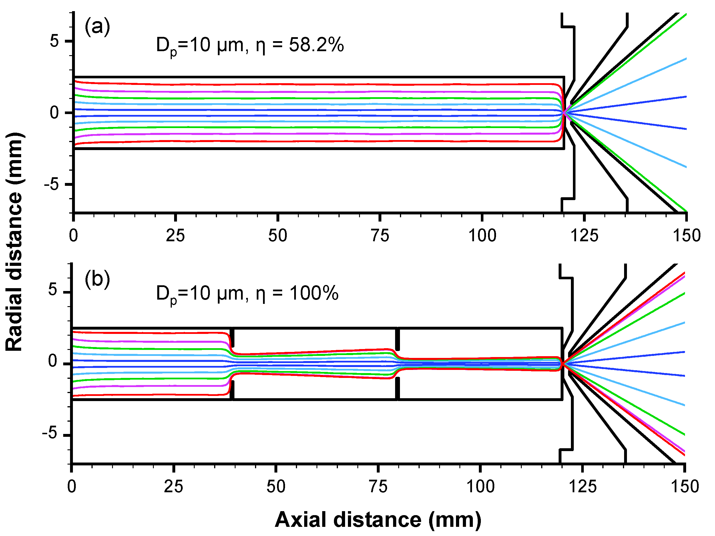
Figure 2 shows a comparison of the theoretical simulation trajectory diagrams for coarse particles (10 μm) with and without the pre-focusing inlet port. The results of Figure 2a shows that coarse particles have partial losses under the condition without the pre-focusing inlet port. This is, on the one hand, due to the larger inertia of the particles after acceleration through the critical orifice that makes the particles lose in the wall of the chamber downstream of the critical orifice [29]. On the other hand, it is due to the inertial deposition on the surface of the critical aperture plate when the particles shrink into the critical orifice, and the farther the axial distance from the aperture, the greater the loss of PM. In order to minimize the loss of large PM before reaching the critical orifice, two focusing holes were added before the inlet port, so that the large PM was pre-focused to the center of the axis before entering the critical orifice. Figure 2b shows the schematic diagram of the pre-focusing inlet port. The simulation particle trajectory results demonstrated that 10 μm PM could achieve 100% focused transmission. When the large PM particles passed through the pre-focusing holes, they were focused on the axis. The key function of the pre-focusing inlet port is to focus PM and form a particle beam before it enters the critical orifice, which prevents PM loss from occurring close to the tube’s wall.
The theoretical transmission efficiency curves of PM with different sizes through the 0.25 mm critical orifice without and with the pre-focusing inlet port are shown in Figure S1 (See Supplementary Information). When the pre-focusing inlet port was not installed, particle loss started to occur as the particle size was larger than 2 μm, and it increased with the particle size. When the particle size was 10 μm, the deposition loss of PM exceeded 40%. The use of the pre-focusing inlet port could significantly enhance the transmission efficiency of the critical orifice for large PM. Even for 15 μm PM, the theoretical transmission efficiency could still reach 100%. In fact, the critical orifice inlet system using the pre-focusing inlet port could also effectively reduce the divergence angle of PM over 500 nm behind the critical orifice.

3.2. Virtual Impact Sampling Cone and Relaxation Chamber

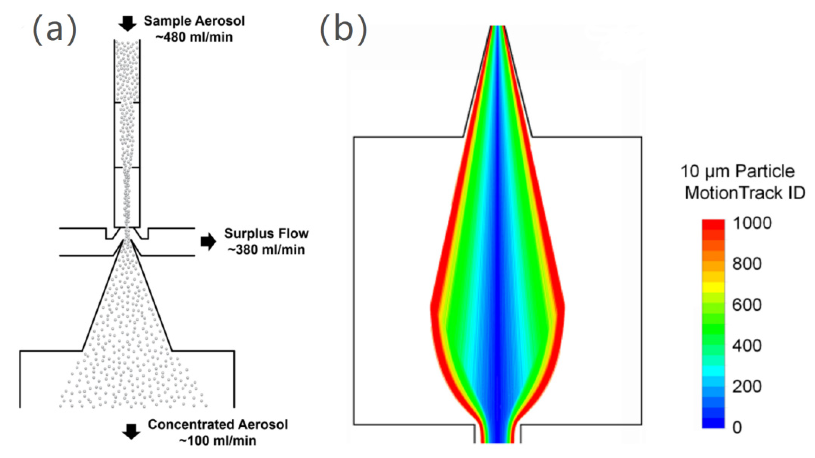
The virtual impact device is often used for sampling atmospheric aerosols and concentrating coarse PM [19]. The basic principle is to separate the partly gas phase and PM phase in sampled airflow. After passing through the critical orifice, the airflow entered the mouth of the sampling cone at a flow rate of about 100 mL/min (Figure 3a). Most PM particles in the aerosol moved with the part of airflow and entered the sampling cone and then, they were concentrated. The remaining excess airflow at about 380 mL/min was drawn off by an additional vacuum pump. Since the PM particles were concentrated without increasing the system’s vacuum load, the pressure of the relaxation chamber located downstream of the sampling cone could be maintained at about ~210 Pa preset by the aerodynamic lens. In addition to concentrating on large PM, the design of virtual impact also has a non-negligible effect on improving the transmission effect of small PM. Wang et al. showed that gas is prone to backflow on the backside of the critical orifice and small PM tends to deposit on the backside of the critical orifice under the backflow, resulting in particle loss [22]. The introduction of the virtual impact sampling cone effectively reduced the backflow phenomenon, thereby further enhancing the transmission efficiency of fine PM.
After PM is accelerated by airflow through a critical orifice, it is usually necessary to set a sufficiently large relaxation area to further reduce the inertial wall loss of large PM. The relaxation chamber usually needs to decelerate the PM particles moving at a high speed, reduce their radial velocity as much as possible, and then guide them into the downstream aerodynamic lens for accomplishing aerodynamic focusing. In order to enhance the transmission efficiency of large PM, the relaxation length and diameter were optimized. Combined with the optimized virtual impact/concentrating device and the seven-stage A-lens, the length, and diameter of the final relaxation chamber were determined to be 250 mm. Figure 3b shows the trajectory of 10 μm particles in the relaxation chamber, which demonstrates that large particles can pass through the relaxation chamber without loss. It is worth noting that a very small diameter or a very short length of the relaxation chamber can cause inertial hit-a-wall loss of large PM.

3.3. Seven-Stage Aerodynamic Lens

The aerodynamic lens generally consists of a single lens with multiple stages of small aperture of different sizes, and its focusing principle has been described in detail by Liu et al. [4,5] The focusing characteristics of the lens on different particles can be described using the particle Stokes number (Stokes, St),
S t = ρ P d P 2 C c u 18 μ d l e n s
where ρ P is the particle density, d P is the particle diameter, C c is the Cunningham slip correction factor, u is the fluid velocity, μ is the fluid viscosity, and d l e n s is the diameter of the lens aperture. The larger the St value, the stronger the focusing effect of the lens on PM and vice versa. However, when the particle St is too high, the PM will be over-focused, causing particle divergence and hit-a-wall loss. When designing a focusing nozzle or lens, the particle St corresponding to the concerned size range is usually controlled to be around 1. For 0.1–1 μm PM, a combination of five lenses with an orifice diameter of about 3–5 mm can be used to achieve non-loss transmission and focus on PM. For focusing PM with a wider size range, most studies adopted seven-stage aerodynamic lenses to enhance the focusing and sampling capability [13,28]. Some studies have pointed out that the loss of large PM at the first lens is mainly due to the relatively large inertia and particle St. When the PM near the periphery of the lens tube passes through the small orifice, more hit-a-wall deposition loss occurs. When other conditions remain unchanged, the particle St is negatively correlated with the aperture. Using a lens with a larger aperture can reduce the particle St. However, the increase in the aperture also increases the ratio between the aperture and the diameter of the lens barrel. The higher the ratio, especially when it is higher than 0.4, the lower the focusing effect on PM.
Therefore, while designing aerodynamic lenses, the apertures of the first-stage and second-stage lenses were designed to be 19 mm and 15 mm, respectively, and the diameter and length of the lens barrel of each stage were designed to be 40 mm. Correspondingly, the particle St values for 10 μm PM were 0.57 and 1.28 and those for 5 μm PM were 0.29 and 0.67, respectively. The lower St and sufficient diameter of the lens barrel allowed PM with a size range of 5–10 μm to pass through lenses 1 and 2 without loss, which completed the preliminary focusing on particles. The particle beam width corresponding to the upstream of the third-stage lens was about 12 mm. Then, PM passed through the following five-stage lens with the apertures gradually becoming smaller and the acceleration nozzle, and then, it completed focused transmission. Here, the acceleration nozzle exhibited a stepped acceleration structure: the nozzle diameter was 3 mm; the thickness of the orifice plate was 0.5 mm, and the diameter and length of the upstream relaxation pipe were 6 mm and 9.5 mm, respectively.
In the seven-stage aerodynamic lenses designed by Lee et al. and Cahill et al. [19,28], the apertures of the final 2–3 stage lens were increased to improve the transmission and focusing of large PM. However, their design purposes were different. The former is because the particle St of 10 μm PM at the fifth-stage lens is greater than 100, which is used to reduce the inertial hit-a-wall deposition loss caused by the transitional focusing on large PM; the latter is because the particle St values at each stage of the lens in the 4–10 μm range are all less than 2.5, which is used to compensate for the focusing effect on large PM. The difference between the two increases in apertures was mainly caused by the different upstream sampling pressures of the aerodynamic lenses: the value for the former was 80 Pa and that for the latter was 3066 Pa. Thus, it can be seen that a very low or very high upstream air pressure of the aerodynamic lens affects the transmission and focusing of coarse PM. In addition, the particle St of small PM is low under high-pressure conditions, due to which the PM cannot be effectively focused. Therefore, in this study, the upstream sampling pressure of the seven-stage aerodynamic lens was designed to be about 210 Pa, and the lens’ aperture was designed in a step-by-step decreasing form. The particle St of 10 μm PM for the overall aerodynamic lens was between 0.5 and 80, as shown in Figure S2. The detailed parameters of the seven-stage aerodynamic lens are shown in Figure 1d.

3.4. Assembly A-Lens Simulation

The motion tracking of PM with different sizes calculated by the FLUENT 2019 R3 software in the wide-range aerosol inlet system are shown in Figure S3. It can be inferred that the wide-range aerosol inlet system designed in this study exhibits excellent transmission and focusing of PM in the size range of 0.05–10 μm. The smaller PM particles have less inertia and the effect of Brownian force [32], they diffuse with the airflow and fill the relaxation chamber, which indicates an obvious random motion. When the airflow contracted, smaller PM particles entered the downstream aerodynamic lens, showing a significant focusing effect from the 3rd and 4th lenses. The sub-micron PM particles pass through the critical orifice and the separation cone, generating a particle accumulation phenomenon similar to that caused by the aerodynamic lens. The main reason is that the St of the sub-micron PM particles at the critical orifice is close to 1. Similarly, as the flow rate decreased, the sub-micron PM particles dispersed in the relaxation chamber and contracted and entered the aerodynamic lens. The PM particles larger than 5 μm move to the middle and downstream of the relaxation chamber and then start to switch from linear motion to shrinking with the airflow. Combined with the lens inlet with a diameter of 40 mm and the transition effect of the first and second lenses, 5 μm and 10 μm PM could be focused and transmitted without loss, due to which the focusing and transmission loss of 10 μm PM particles could be effectively overcome by using the SPAMS inlet system reported in this study.
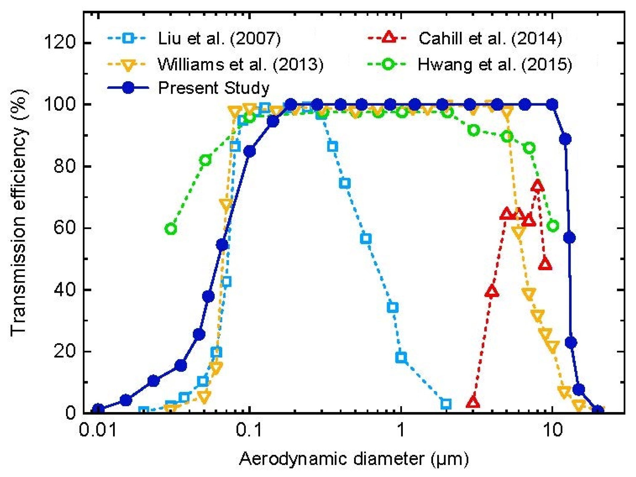
In Figure 4, we have compared the theoretical particle transmission efficiency of the wide-range aerosol inlet system with previously reported results. Williams et al. [13] increased the transmission efficiency of PM over 1 μm by increasing the sampling pressure of the lens and by increasing the stage number of the lens to 7. As a result, nearly 100% theoretical transmission efficiency was obtained in the particle size range of 0.08–5 μm, but the transmission efficiency of 10 μm particles was only 22%. Cahill et al. [19] used a high-pressure seven-stage A-lens inlet system, which effectively enhanced the transmission efficiency of 4–10 μm PM; however, the focusing capability for PM below 3 μm was relatively low, and the overall transmission efficiency was not higher than 80%. Subsequently, Hwang et al. [29] proposed an ideal C-D critical orifice sampling structure combined with a seven-stage A-lens, which could achieve 100% transmission efficiency of PM in the range of 0.1–2 μm; however, the transmission efficiency of PM over 2 μm began to decrease as the particle size increased, and the particle transport efficiency of 10 μm PM was 60%. The wide-range aerosol inlet system developed in this study realizes non-loss focused transmission and inlet for the particle size range of 0.18–10 μm, covering two orders of magnitude. The 50% fractional particle sizes were 62 nm and 13 μm, indicating significant improvement in the application capability of the current SPAMS.
When the inlet lens system is used on SPAMS, in addition to the transmission efficiency, there are higher requirements for the focused particle beam width. The beam width distribution curves of PM with different sizes at 40 mm and 120 mm downstream after passing through the acceleration nozzle of the wide-range aerosol inlet system are shown in Figure S4. In the size range of 0.2–10 μm, the overall beam width of PM concentrates around 0.3 mm at 40 mm downstream of the nozzle. Therefore, the focused particle beam matched the sizing laser (spot size 0.3 mm) detection performance satisfactorily. Similar to the observation for common aerodynamic lenses, when the particle size was less than 0.15 μm, the divergence of the particle beam increased with the decrease in particle size because of the “Brown broadening phenomenon” [22]. For particle size over 10 μm, the increase in beam width is caused by the particle’s inertial divergence. Overall, the wide-range aerosol inlet system can achieve ideal focusing effects in the size range of 0.15–10 μm, which can meet the single particle detection requirements of SPAMS.

3.5. Experiment Characterization

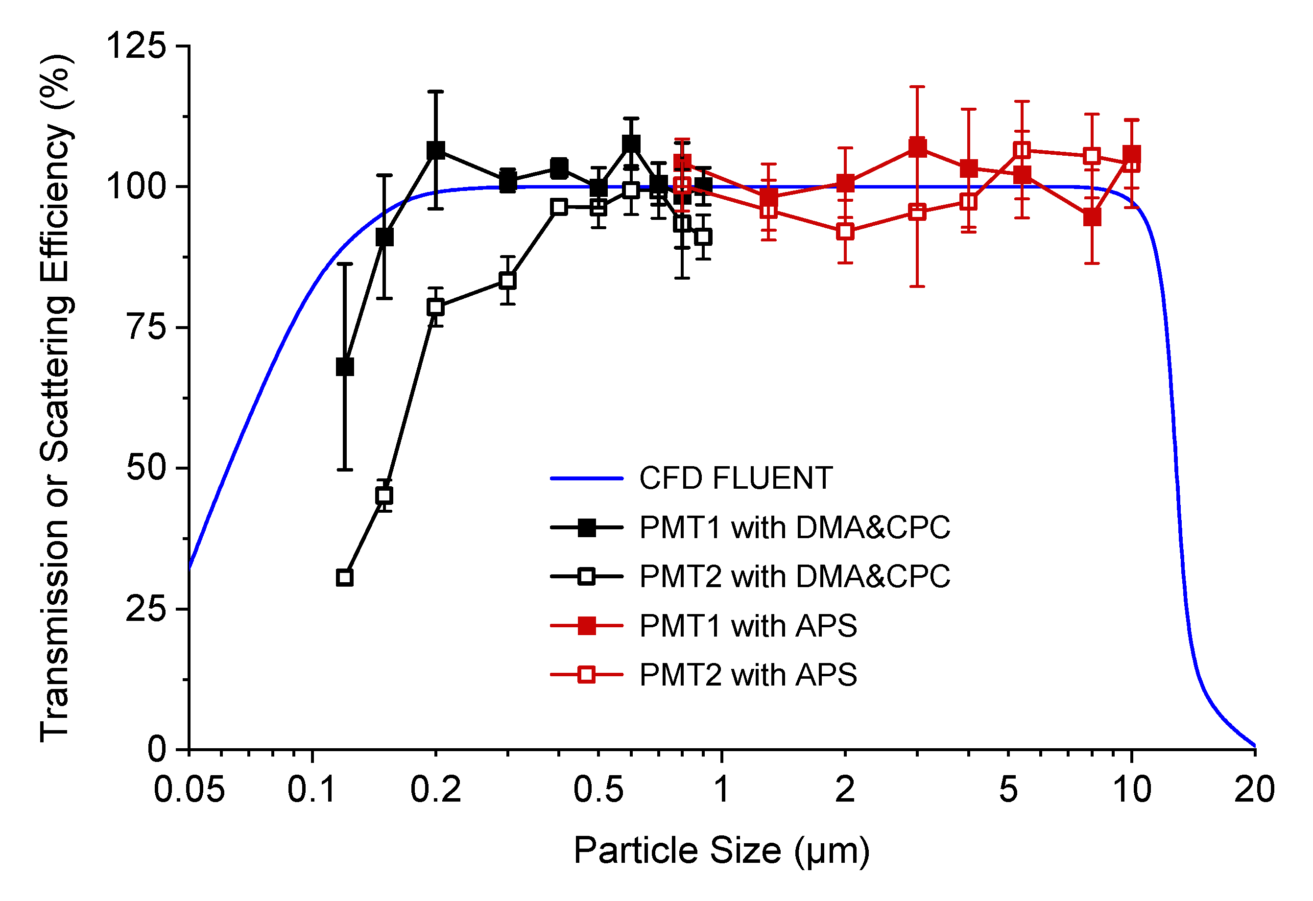
Figure 5 shows the comparison of the theoretical transmission efficiency and the experimental scattering efficiency of the designed aerosol inlet system. In the experiment, the pulse numbers of the two PMT beams were counted respectively. PMT1 and PMT2 were 6 cm and 12 cm away from the outlet of the lens system, respectively. The scattering efficiency of the lens system could be estimated by the pulse number of PMT1 and PMT2 by using Equation (1). In the entire particle size range of 120 nm–10 μm, the scattering efficiency calculated through PMT1 counting was consistent with the theoretical simulation. In the particle size range of 200 nm–10 μm, the transmission efficiency of PM was close to 100%. The scattering efficiency of PM below 200 nm showed a downward trend. The reasons are as follows: a small PM increases the beam width and the weaker scattered light signal is generated by a small PM at the edge of the scattered laser beam. For PM smaller than 0.4 μm, the scattering efficiency obtained from PMT2 counting was lower than that obtained from PMT1 counting, indicating that the divergence of small PM was more significant. Overall, when the wide-range aerosol inlet system was combined with the present SPAMS, it could achieve efficient focusing transmission of 120 nm–10 μm PM, and the experimental results were remarkably consistent with the theoretical predictions.
The time of flight of the particles between the two sizing laser beams can be calculated from the response pulse time interval of the PMT, which is related to the particle size and the velocity after the exit of the aerodynamic lens. The measured time-of-flight versus particle number normalized distribution of particles between 0.12 μm and 10 μm is shown in Figure S5. Using the equation d v a = a T b to fit the time of flight versus particle size, the R-squared can reach 0.9998.
Figure 6 shows the detected particle size distributions of three aerosol samples: bacterium and fungus. It can be seen that the particle size distribution of the bacterium aerosol is mainly between 0.5 μm and 2 μm, whereas that of the fungus aerosol is significantly wider, i.e., from 100 nm to 10 μm; this also indicates that the newly designed aerodynamic lens system is suitable for a wider particle size range and can effectively detect bioaerosols with a particle size up to 10 μm.

4. Conclusions

In order to enhance the detection capability of the SPAMS inlet system for large PM, in this study, we developed an aerodynamic lens inlet system with focusing capability for wider particle sizes. The innovative pre-focusing inlet port could effectively solve the problem of the loss of large PM caused by impact and collision before it enters the aerodynamic lens, thereby considerably enhancing the transmission efficiency of coarse PM. Numerical simulations indicated that this complete set of devices could achieve a non-loss-focused inlet and transmission for PM with a size range of 180 nm–10 μm, indicating high particle transmission efficiency. The results confirmed that the transmission efficiency was nearly 100% for PM with a size range of 200 nm–10 μm. So far, it is an aerodynamic lens inlet system reported in the literature with the widest particle size range and the highest transmission efficiency. The focusing capability of the system for PM with a wide size range can significantly increase the applications of SPAMS, and the system has broad application prospects in the study of coarse PM such as biological single cells, biological aerosols, sea salt, and sand dust.

Supplementary Materials

The following supporting information can be downloaded at: https://www.mdpi.com/article/10.3390/atmos14040664/s1, Figure S1: The transmission efficiency of PM with different sizes with and without pre-focusing; Figure S2: Particle Stokes number (St) distribution of PM with different sizes at the orifice position of every lens; Figure S3: Simulation on particle transmission track in the full-size range; Figure S4: Numerical simulation results of particle beam radius at 40 mm and 120 mm downstream of the acceleration nozzle; Figure S5: Particle size curve calibrated using PSL microspheres.

Author Contributions

L.L., X.D. and Z.Z. (Zeming Zhuo) designed the study; Z.Z. (Zeming Zhuo), X.D., X.L. (Xuan Li) and J.Y. performed the experiments; X.L. (Xue Li), X.D., J.Y., Z.Z. (Zeming Zhuo) and M.L. participated in data analysis and result discussion; X.D., Z.Z. (Zeming Zhuo) and L.L. wrote the paper with the input from all authors. W.G. and Z.H. provided SPAMS instrument resources. L.L. and Z.Z. (Zhen Zhou) are project administration. All authors have read and agreed to the published version of the manuscript.

Funding

This research was funded by the National key research and development program for young scientists (2022YFF0705400).

Institutional Review Board Statement

Not applicable.

Informed Consent Statement

Not applicable.

Data Availability Statement

Not applicable.

Conflicts of Interest

The authors declare no conflict of interest.

References

  1. Clemen, H.-C.; Schneider, J.; Klimach, T.; Helleis, F.; Köllner, F.; Hünig, A.; Rubach, F.; Mertes, S.; Wex, H.; Stratmann, F.; et al. Optimizing the detection, ablation, and ion extraction efficiency of a single-particle laser ablation mass spectrometer for application in environments with low aerosol particle concentrations. Atmos. Meas. Tech. 2020, 13, 5923–5953. [Google Scholar] [CrossRef]
  2. Li, L.; Huang, Z.; Dong, J.; Li, M.; Gao, W.; Nian, H.; Fu, Z.; Zhang, G.; Bi, X.; Cheng, P.; et al. Real time bipolar time-of-flight mass spectrometer for analyzing single aerosol particles. Int. J. Mass Spectrom. 2011, 303, 118–124. [Google Scholar] [CrossRef]
  3. Pratt, K.A.; Mayer, J.E.; Holecek, J.C.; Moffet, R.C.; Sanchez, R.O.; Rebotier, T.P.; Furutani, H.; Gonin, M.; Fuhrer, K.; Su, Y.; et al. Development and characterization of an aircraft aerosol time-of-flight mass spectrometer. Anal. Chem. 2009, 81, 1792–1800. [Google Scholar] [CrossRef]
  4. Liu, P.; Ziemann, P.J.; Kittelson, D.B.; McMurry, P.H. Generating Particle Beams of Controlled Dimensions and Divergence: II. Experimental Evaluation of Particle Motion in Aerodynamic Lenses and Nozzle Expansions. Aerosol Sci. Technol. 1995, 22, 314–324. [Google Scholar] [CrossRef]
  5. Liu, P.; Ziemann, P.J.; Kittelson, D.B.; McMurry, P.H. Generating Particle Beams of Controlled Dimensions and Divergence: I. Theory of Particle Motion in Aerodynamic Lenses and Nozzle Expansions. Aerosol Sci. Technol. 1995, 22, 293–313. [Google Scholar] [CrossRef] [Green Version]
  6. Murphy, D.M.; Cziczo, D.J.; Froyd, K.D.; Hudson, P.K.; Matthew, B.M.; Middlebrook, A.M.; Peltier, R.E.; Sullivan, A.; Thomson, D.S.; Weber, R.J. Single-particle mass spectrometry of tropospheric aerosol particles. J. Geophys. Res. Atmos. 2006, 111, 1–15. [Google Scholar] [CrossRef] [Green Version]
  7. Gemayel, R.; Hellebust, S.; Temime-Roussel, B.; Hayeck, N.; Van Elteren, J.T.; Wortham, H.; Gligorovski, S. The performance and the characterization of laser ablation aerosol particle time-of-flight mass spectrometry (LAAP-ToF-MS). Atmos. Meas. Tech. 2016, 9, 1947–1959. [Google Scholar] [CrossRef] [Green Version]
  8. Zelenyuk, A.; Imre, D.; Wilson, J.; Zhang, Z.; Wang, J.; Mueller, K. Airborne single particle mass spectrometers (SPLAT II & miniSPLAT) and new software for data visualization and analysis in a geo-spatial context. J. Am. Soc. Mass Spectrom. 2015, 26, 257–270. [Google Scholar] [CrossRef] [Green Version]
  9. Hinz, K.-P.; Kaufmann, R.; Spengler, B. Laser-Induced Mass Analysis of Single Particles in the Airborne State. Anal. Chem. 2002, 66, 2071–2076. [Google Scholar] [CrossRef]
  10. Prather, K.A.; Nordmeyer, T.; Salt, K. Real-time characterization of individual aerosol particles using time-of-flight mass spectrometry. Anal. Chem. 1994, 66, 1403–1407. [Google Scholar] [CrossRef]
  11. Steele, P.T.; Tobias, H.J.; Fergenson, D.P.; Pitesky, M.E.; Horn, J.M.; Czerwieniec, G.A.; Russell, S.C.; Lebrilla, C.B.; Gard, E.E.; Frank, M. Laser power dependence of mass spectral signatures from individual bacterial spores in bioaerosol mass spectrometry. Anal. Chem. 2003, 75, 5480–5487. [Google Scholar] [CrossRef] [PubMed]
  12. Frank, M.; Gard, E.E.; Tobias, H.J.; Adams, K.L.; Bogan, M.J.; Coffee, K.R.; Farquar, G.R.; Fergenson, D.P.; Martin, S.I.; Pitesky, M.; et al. Single-Particle Aerosol Mass Spectrometry (SPAMS) for High-Throughput and Rapid Analysis of Biological Aerosols and Single Cells. In Rapid Characterization of Microorganisms by Mass Spectrometry; ACS Symposium Series; American Chemical Society: New York, NY, USA, 2011; pp. 161–196. [Google Scholar]
  13. Williams, L.R.; Gonzalez, L.A.; Peck, J.; Trimborn, D.; McInnis, J.; Farrar, M.R.; Moore, K.D.; Jayne, J.T.; Robinson, W.A.; Lewis, D.K.; et al. Characterization of an aerodynamic lens for transmitting particles greater than 1 micrometer in diameter into the Aerodyne aerosol mass spectrometer. Atmos. Meas. Tech. 2013, 6, 3271–3280. [Google Scholar] [CrossRef] [Green Version]
  14. Zhang, X.; Smith, K.A.; Worsnop, D.R.; Jimenez, J.; Jayne, J.T.; Kolb, C.E. A Numerical Characterization of Particle Beam Collimation by an Aerodynamic Lens-Nozzle System: Part I. An Individual Lens or Nozzle. Aerosol Sci. Technol. 2002, 36, 617–631. [Google Scholar] [CrossRef]
  15. Zhang, X.; Smith, K.A.; Worsnop, D.R.; Jimenez, J.L.; Jayne, J.T.; Kolb, C.E.; Morris, J.; Davidovits, P. Numerical Characterization of Particle Beam Collimation: Part II Integrated Aerodynamic-Lens–Nozzle System. Aerosol Sci. Technol. 2004, 38, 619–638. [Google Scholar] [CrossRef] [Green Version]
  16. Lee, K.-S.; Cho, S.-W.; Lee, D. Development and experimental evaluation of aerodynamic lens as an aerosol inlet of single particle mass spectrometry. J. Aerosol Sci. 2008, 39, 287–304. [Google Scholar] [CrossRef]
  17. Steele, P.; McJimpsey, E.; Coffee, K.; Fergenson, D.; Riot, V.; Tobias, H.; Woods, B.; Gard, E.; Frank, M. Characterization of Ambient Aerosols at the San Francisco International Airport Using Bioaerosol Mass Spectrometry; SPIE: Kissimmee, FL, USA, 2006; Volume 6218. [Google Scholar]
  18. Martin, A.N.; Farquar, G.R.; Frank, M.; Gard, E.E.; Fergenson, D.P. Single-particle aerosol mass spectrometry for the detection and identification of chemical warfare agent simulants. Anal. Chem. 2007, 79, 6368–6375. [Google Scholar] [CrossRef]
  19. Cahill, J.F.; Darlington, T.K.; Wang, X.; Mayer, J.; Spencer, M.T.; Holecek, J.C.; Reed, B.E.; Prather, K.A. Development of a High-Pressure Aerodynamic Lens for Focusing Large Particles (4–10 μm) into the Aerosol Time-of-Flight Mass Spectrometer. Aerosol Sci. Technol. 2014, 48, 948–956. [Google Scholar] [CrossRef]
  20. Cahill, J.F.; Darlington, T.K.; Fitzgerald, C.; Schoepp, N.G.; Beld, J.; Burkart, M.D.; Prather, K.A. Online analysis of single cyanobacteria and algae cells under nitrogen-limited conditions using aerosol time-of-flight mass spectrometry. Anal. Chem. 2015, 87, 8039–8046. [Google Scholar] [CrossRef]
  21. Zawadowicz, M.A.; Froyd, K.D.; Murphy, D.M.; Cziczo, D.J. Improved identification of primary biological aerosol particles using single-particle mass spectrometry. Atmos. Chem. Phys. 2017, 17, 7193–7212. [Google Scholar] [CrossRef] [Green Version]
  22. Wang, X.; Kruis, F.E.; McMurry, P.H. Aerodynamic Focusing of Nanoparticles: I. Guidelines for Designing Aerodynamic Lenses for Nanoparticles. Aerosol Sci. Technol. 2005, 39, 611–623. [Google Scholar] [CrossRef]
  23. Wang, X.; McMurry, P.H. An experimental study of nanoparticle focusing with aerodynamic lenses. Int. J. Mass Spectrom. 2006, 258, 30–36. [Google Scholar] [CrossRef]
  24. Wang, X.; McMurry, P.H. A Design Tool for Aerodynamic Lens Systems. Aerosol Sci. Technol. 2006, 40, 320–334. [Google Scholar] [CrossRef]
  25. Schreiner, J.; Schild, U.; Voigt, C.; Mauersberger, K. Focusing of Aerosols into a Particle Beam at Pressures from 10 to 150 Torr. Aerosol Sci. Technol. 1999, 31, 373–382. [Google Scholar] [CrossRef] [Green Version]
  26. Berninger, R.W.; Booker, S.V.; Talamo, R.C. Serum prealbumin levels in alpha 1-antitrypsin deficiency (PiZ). Metabolism 1982, 31, 299–302. [Google Scholar] [CrossRef]
  27. Gard, E.; Riot, V.; Coffee, K.; Woods, B.; Tobias, H.; Birch, J.; Weisgraber, T. Pressure-Flow Reducer for Aerosol Focusing Devices. U.S. Patent 7,361,891, 22 April 2008. [Google Scholar]
  28. Lee, K.-S.; Hwang, T.-H.; Kim, S.-H.; Kim, S.H.; Lee, D. Numerical Simulations on Aerodynamic Focusing of Particles in a Wide Size Range of 30 nm–10 μm. Aerosol Sci. Technol. 2013, 47, 1001–1008. [Google Scholar] [CrossRef]
  29. Hwang, T.-H.; Kim, S.-H.; Kim, S.H.; Lee, D. Reducing particle loss in a critical orifice and an aerodynamic lens for focusing aerosol particles in a wide size range of 30 nm–10 μm. J. Mech. Sci. Technol. 2015, 29, 317–323. [Google Scholar] [CrossRef]
  30. Das, R.; Phares, D.J. Expansion of an ultrafine aerosol through a thin-plate orifice. J. Aerosol Sci. 2004, 35, 1091–1103. [Google Scholar] [CrossRef]
  31. Liu, P.S.K.; Deng, R.; Smith, K.A.; Williams, L.R.; Jayne, J.T.; Canagaratna, M.R.; Moore, K.; Onasch, T.B.; Worsnop, D.R.; Deshler, T. Transmission Efficiency of an Aerodynamic Focusing Lens System: Comparison of Model Calculations and Laboratory Measurements for the Aerodyne Aerosol Mass Spectrometer. Aerosol Sci. Technol. 2007, 41, 721–733. [Google Scholar] [CrossRef]
  32. Abouali, O.; Nikbakht, A.; Ahmadi, G.; Saadabadi, S. Three-Dimensional Simulation of Brownian Motion of Nano-Particles in Aerodynamic Lenses. Aerosol Sci. Technol. 2009, 43, 205–215. [Google Scholar] [CrossRef]
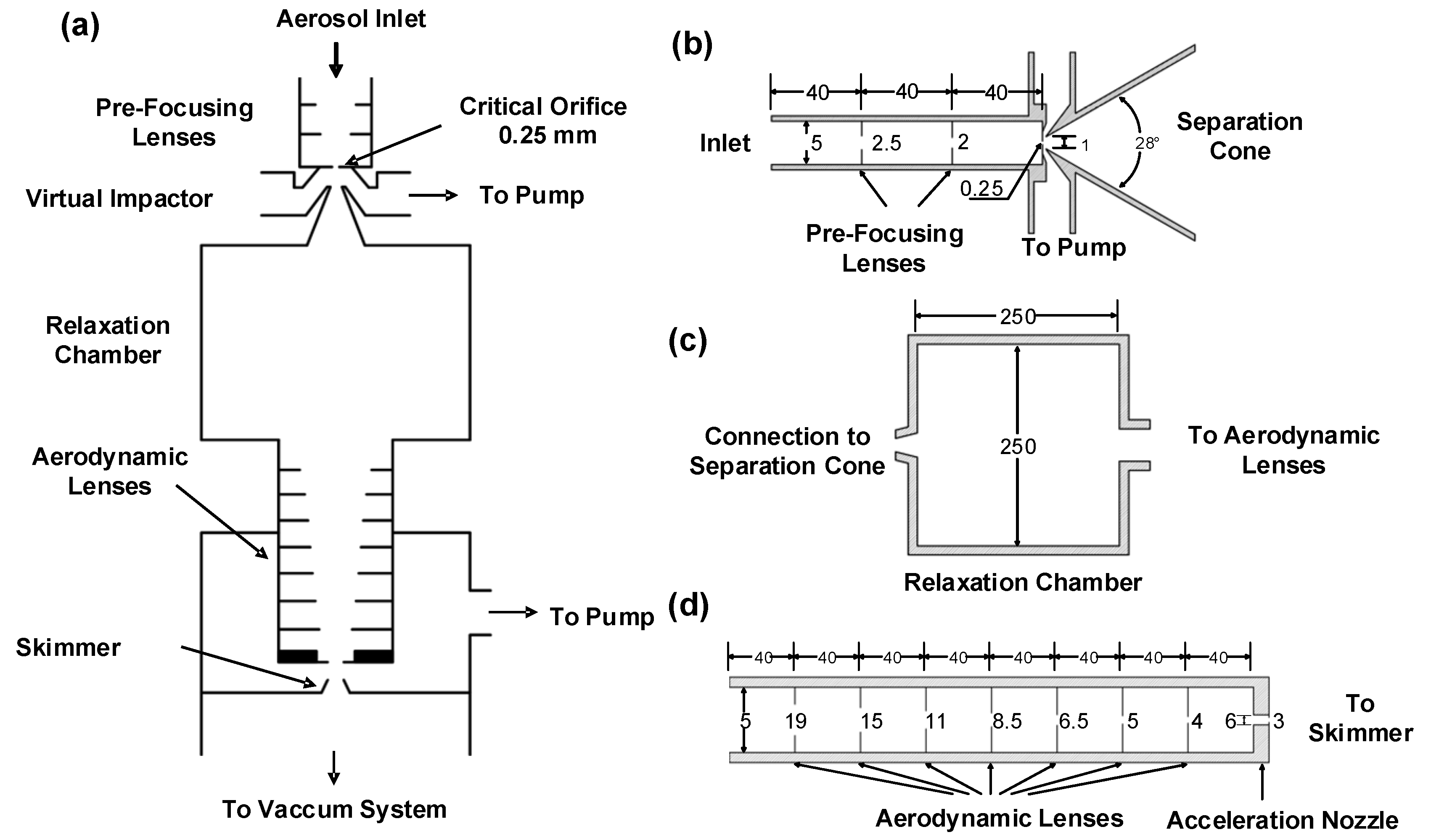
Figure 1. (a) Schematic diagram of the wide-range aerosol inlet system; (b) the pre-focusing leans and separation cone; (c) relaxation chamber; (d) aerodynamic lens.
Atmosphere 14 00664 g001
Figure 2. Simulation of the transmission trajectories of 10 μm PM without (a) and with (b) the pre-focusing inlet ports. The colors represent the trajectory of the particles at different locations.
Atmosphere 14 00664 g002
Figure 3. (a) Schematic diagram of the design of the virtual impactor; (b) Trajectory of 10 µm particles in the relaxation chamber.
Atmosphere 14 00664 g003
Figure 4. Comparison between theoretical simulated and previously reported transmission efficiencies of wide-range lens systems [13,20,29,31].
Atmosphere 14 00664 g004
Figure 5. The comparison of the theoretical transmission efficiency and the experimental scattering efficiency of the designed aerosol inlet system.
Atmosphere 14 00664 g005
Figure 6. Particle size distribution of Escherichia coli, Enterococcus faecium, and Aspergillus brasiliensis.
Atmosphere 14 00664 g006
Disclaimer/Publisher’s Note: The statements, opinions and data contained in all publications are solely those of the individual author(s) and contributor(s) and not of MDPI and/or the editor(s). MDPI and/or the editor(s) disclaim responsibility for any injury to people or property resulting from any ideas, methods, instructions or products referred to in the content.