Article

Synergistic Effect Evaluation of Slot-Type Nozzle Area, Jet Pressure and Jet Distance on Improving Deashing Performance of Flat CARTRIDGE Filter

School of Environment and Resource, Southwest University of Science and Technology, Mianyang 621010, China
*
Author to whom correspondence should be addressed.
Atmosphere 2023, 14(2), 325; https://doi.org/10.3390/atmos14020325
Submission received: 1 December 2022 / Revised: 2 February 2023 / Accepted: 3 February 2023 / Published: 6 February 2023
(This article belongs to the Special Issue Control and Purification of Particulate Matter)

Abstract

:

Highlights

What are the main findings?
  • 819 mm2 of nozzle area leads to the best deashing performance.
  • 0.3 MPa of jet pressure leads to the best deashing uniformity.
What is the implication of the main finding?
  • Bigger nozzle area causes bigger on-positive nozzle pressure.
  • 819 mm2, 0.3 MPa and 20 mm were optimized to get the best deashing performance.

Abstract

The difference of deashing performance between the areas of positive-to-blowing holes and that of non-positive-to-blowing holes is an important problem that causes a non-uniform deashing performance to a flat box filter cartridge, which limits the improvement of raising the ash cleaning efficiency to this kind of filter. In order to solve the above problems, the influence of blowing pressure, blowing distance and blowing hole area on cleaning performance was studied. Industrial coating test was also carried out to investigate and verify the actual ash cleaning performance under the optimal conditions obtained from the above investigations. Finally, the design method of the size of the slotted blowing hole was optimized. The results showed that at 0.3 MPa of the pulse pressure, the cleaning performance can meet the cleaning requirements and the best cleaning uniformity can be obtained. With the increase in slot-type nozzle area, the pressure at the areas facing the non-positive nozzles increased significantly, and thus the overall cleaning uniformity increased. The slot-type nozzle area of 273, 546 and 819 mm2 had the best cleaning effects at the jet distances of 40, 20~40 and 20 mm, respectively. The findings of this study are of great significance and can provide theoretical and experimental reference for important parameters selection of the flat cartridges filter in industrial application to improve the efficiency of dust removal.

1. Introduction

Cartridge filters have been widely used industrially due to their small volume, high filtration efficiency and the fact they are easy to maintain [1,2]. To solve the problem of dust collection in confined spaces and local work areas in industrial practice, a new type of cartridge—a flat cartridge—has been applied to industrial dust collection in recent years [3,4]. The structure of the flat cartridge filter is similar to that of the circular filter, both of which are fold structures. However, the shape of the flat cartridge filter is rectangular, so it is more economical to floor space and more convenient for cleaning [5,6].
A nozzle is an important factor affecting the cleaning performance of the cartridge, as shape, size, and area affect the cleaning uniformity of the cartridge. Therefore, a lot of researchers have studied the effects of the nozzles with different structure on the cleaning performance of the cartridge [7,8,9]. Li et al. [10] proposed a new deashing method of impact pulse jet for the cartridge. The experiment shows that although the cleaning performance is improved by impact jet without time difference, the air consumption is huge. Chen [11] comparatively analyzed the jet velocity fields and pressure fields between the ordinary circular nozzle and annular slot-type nozzle by numerical simulation and believed that the pressure distribution is more uniform on the upper part of the cartridge with annular slot-type nozzles. Shim et al. [12] designed a new type of nozzle with double slot type and comparatively analyzed both the dust emission and system pressure drop by injection hole, single nozzle and double slot nozzle. Their experiments proved that the double slot nozzle has a better cleaning effect and lower dust emission. Li et al. [13] optimized the diameters of the five nozzles in the gas jet direction by taking the complex pressure as an evaluation index. Their research results show that both the pressure uniformity on the inner wall of the cartridge and the instantaneous pressure drop below the nozzles with optimal diameters are greatly improved. Yan et al. [14] used traditional circular nozzles to explore the characteristics of the flat cartridge for the first time and found that the traditional round nozzles could not effectively remove the dust on the upper parts of the cartridges with non-positive nozzles.
The flat cartridge has a special rectangular structure. Several circular nozzles are usually used to jet one cartridge, so two special cleaning areas could be formed of the cartridge: the area positive-to-nozzles and the area non-positive-to-nozzles (as shown in Figure 1). With increasing operation time, it is very difficult for the flat cartridge to collect dust, so a large amount of dust accumulated upon the area of the non-positive-to-nozzles [15,16,17] and greatly reduced the effective filtration area of the flat cartridge. As a new type of cartridge nozzle, the slot-type pulse nozzle is the most economical and effective means to improve the cleaning performance of flat cartridges at present. The study on the jet effect of the slot-type pulse nozzle and improvement of the cleaning performance of the flat cartridge is an effective way to expand its application market [18,19]. With the deepening of research, the round hole injection is applied to ash removal of flat cartridge filter. Li et al. [10] found that the residual dust was sandwiched between two adjacent injection holes (about 40–60% of total residual dust). Kang et al. [20] first designed and compared 1*39 mm slot-type nozzles with the traditional circular nozzles. The analysis shows that the slot nozzles can eliminate the defects of the non-positive nozzles to a certain extent but fail to solve the problem of uneven gas distribution.
In general, there are few studies on the cleaning performance of flat cartridge filter, and only a few studies have conducted preliminary studies on this [21], but the results show that there are difficulties in ash removal in the non-opposite area of the upper part of the filter cartridge [20]. In order to eliminate the defects of the non-opposite areas and improve the cleaning uniformity of the cartridge, the cleaning performance of the flat cartridge was explored by pulse jet and industrial dust-coated experiments based on the original research of the research group according to the structural characteristics of the flat cartridge [22,23,24]. The study on the effect of the optimal nozzle area on the cleaning effect of the flat cartridge is of great significance in relation to the improvement of the industrial production and cleaning efficiencies of the flat cartridge.

2. Pulse Jet Experiment

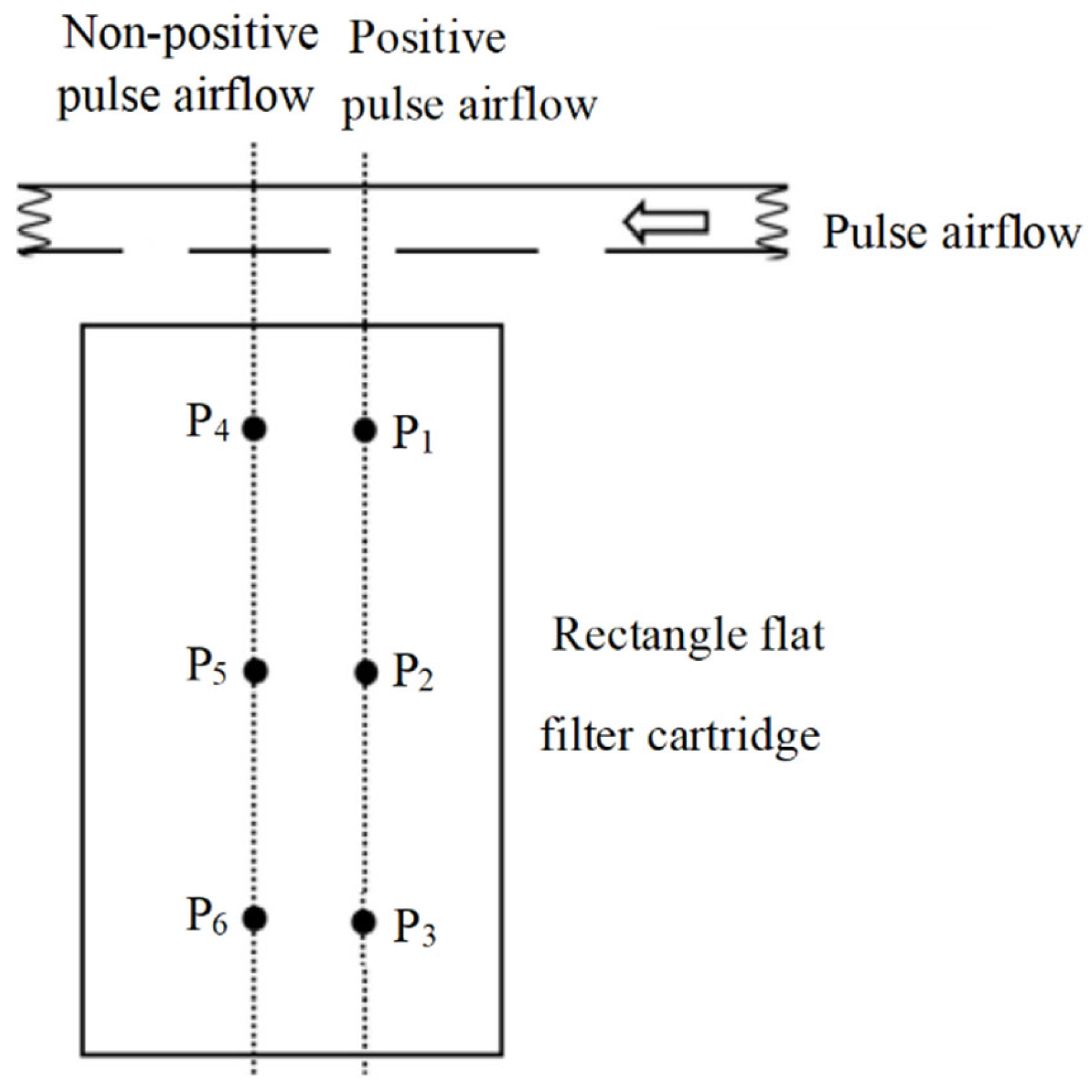
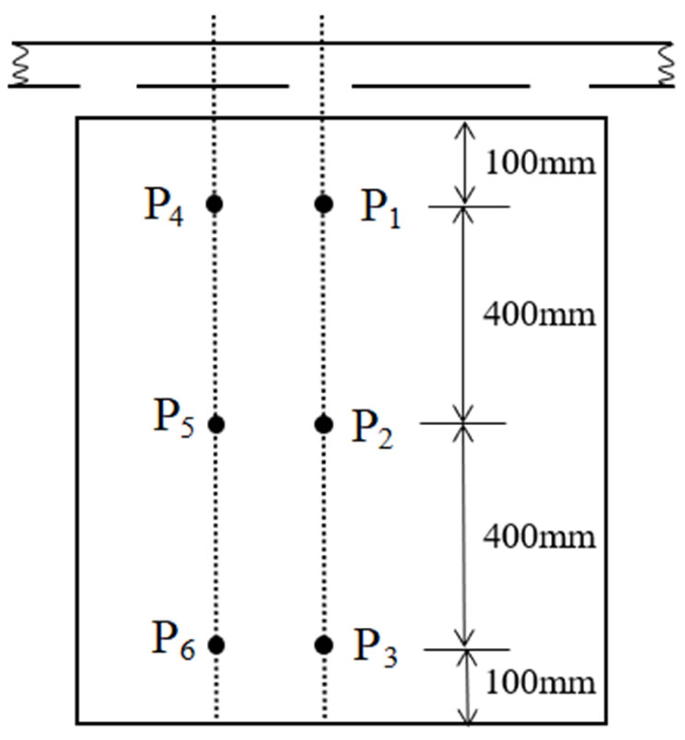
2.1. Experimental Device and Design

Figure 2 shows the schematic diagram of the pulse jet test bench consisting of a gas supply system, jet system and pressure test system. The gas supply system consisted of a HAD-1SNF freeze-drying machine, WW-0.9/10B-Q air compressor, and gas tank. The jet system consisted of SXC-8A1 pulse controller, 24 L air bag (wall thickness: 7.5 mm), DMF-ZM-25 1” solenoid valve, jet pipe (Length: 1200 mm. Diameter: 28 mm), rectangular flat cartridge (length: 470 mm, width: 64 mm, height: 1000 mm, pleat depth: 31 mm, 33 pleats at a single side, filtration area: 4.3 m2), etc. The pressure test system consisted of a charge-amplifier and the data acquisition system. The test data acquisition system consisted of six pressure transducers, a charge-amplifier, a data acquisition instrument and a computer (with OSA software). The acquisition accuracy of the high-sensitivity pressure sensor was 0.1 Pa.

2.2. Test Method and Evaluation Criteria

In order to explore the effects of jet distance and pulse pressure on the cleaning performance of flat cartridges at different slot-type nozzle areas, six reference points were distributed on the surface of the flat cartridge, and the pressure peak on the inner surface of the flat cartridge was measured by the pressure sensor [25,26]. The industrial dust-coated experimental results showed that the cartridge could meet the requirement for pulverized fuel ash cleaning at the average peak pressure (AP) above 500~600 Pa on its inner surface [25,26]. Therefore, the peak pressure of 600 Pa on the sidewall was taken as an evaluation index in the pulse jet experiment to preliminarily determine whether it met the requirement for deashing of the flat cartridge. The relative standard deviation (RSD) was calculated as an index to evaluate the pressure distribution uniformity on the surface of the cartridge. On the basis of comprehensively considering the influence of the peak pressure and the pressure uniformity on dust removal behavior, a comprehensive index called integrated pressure by using entropy weight method to comprehensively evaluate the dust removal performance of the rectangular box filter was proposed by Zhang et al. [27]. This paper verifies this standard. The integrated pressure is denoted as Pc (unit of Pa), which can be written as:
P c = α 1 P 1 + + α n P n
α i = n i i = 1 6 n
n i = max ( P 1 P i ) P i max ( P 1 P i ) min ( P 1 P i )
where i , which is 1 to 6 in this work, represents the number of measuring points on the sidewall of the filter cartridge, Pi is the pressure peak of the sidewall at each measuring point, and αi is the weight coefficient of each measuring point. Distribution of reference points: 6 reference points (i.e., reference points P 1 ~ P 6 ) in two rows were distributed along the length of the cartridge. P 1 ~ P 3 were opposite to the slot-type nozzles, while P 4 ~ P 6 are located between the two nozzles (i.e., not opposite to the nozzles). As shown in Figure 3, P 1 and P 4 , P 2 and P 5 , and P 3 and P 6 were 100, 500, and 900 mm far from the cartridge opening, respectively.
In order to ensure the accuracy of the test, each group was tested 6 times and the average on six tests was taken as the test result.
Four kinds of slot-type nozzles with different nozzle areas were designed for the test. Their design parameters are shown in Table 1.

2.3. Result and Discussion

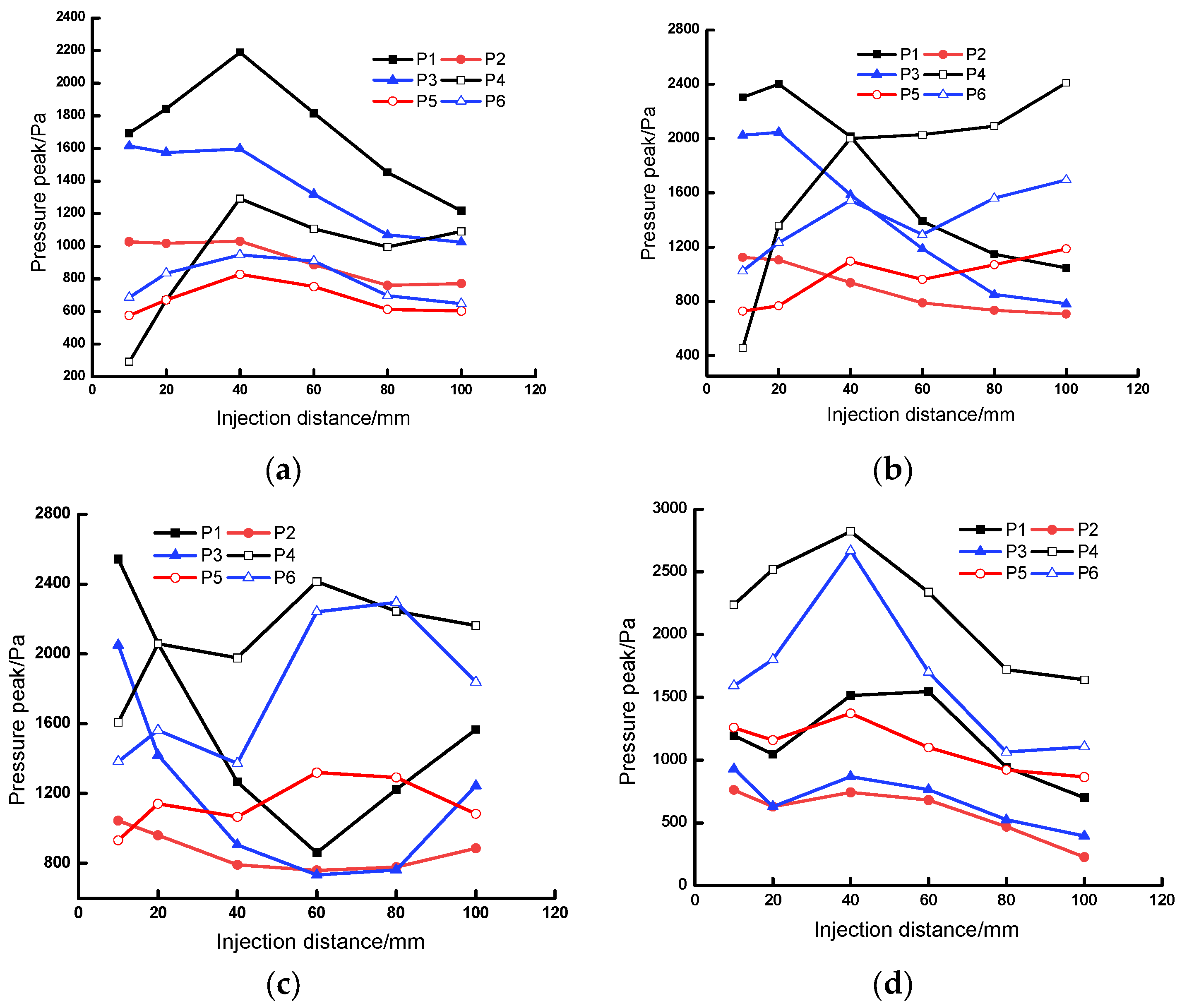
2.3.1. Effect of Jet Distance on Peak Pressure of the Flat Cartridge

Figure 4 shows the change of the peak pressure on the sidewalls of the flat cartridges with different nozzle areas at different jet distances at the pulse pressure of 0.3 MPa.
It can be seen from Figure 4a that, with increasing jet distance, the peak pressure at the nozzle with a total nozzle area of 273 mm2 increased first and then decreased. Moreover, an opposite nozzle had greater peak pressure than a non-positive nozzle. P4 had the smallest peak pressure at the jet distance below 20 mm because the gas flow from the nozzle did not cover the upper part of the non-positive nozzle at a small jet distance. With increasing jet distance, the gas flow gradually diffused and induced more gas to enter the flat cartridge. At the jet distance above 40 mm, the peak pressures at all reference points began to decrease since, at a large jet distance, more jet gas flow escaped outside the flat cartridge during diffusion and thus the gas flow obtained by the flat cartridge reduced.
It can also be seen from Figure 4a that, at the jet distance of 10 mm, both P4 and P5 showed a peak pressure of less than 600 Pa, indicating that it is difficult to reach the required cleaning performance at this jet distance. Table 2 shows the average pressure and relative standard deviation of pressure at the total area of different nozzles. It can be seen from Table 2 that, with increasing jet distance, the AP increased first and then decreased, and the RSD gradually decreased. According to Figure 4 and Table 2, there was a small difference in AP and a large difference in RSD at the jet distance of 40 mm and the Pc was calculated. The results are provided in Table 3. The maximum Pn was when the jet distance is 40 mm. Thus, it was preliminarily determined that the nozzle with a total nozzle area of 273 mm2 had the optimal jet distance of 40 mm. That will be subsequently verified by an industrial dust test.
Figure 4b reveals that, with increasing jet distance, the induced amount of injection airflow increased, and the conversion from dynamic pressure to static pressure of airflow increased, but it also caused the acceleration of pressure attenuation. The peak pressure at the opposite nozzles first increased and then decreased, and at the non-positive nozzles gradually increased. Apart from P4, the other reference points reached the required cleaning performance at the jet distance of 10 mm. Comprehensive consideration of cleaning performance and uniformity indicates that the nozzle with a total nozzle area of 546 mm2 had the optimal jet distance of 20~40 mm.
It can be seen from Figure 4c that, with increasing jet distance, the peak pressure at the opposite nozzles first decreased and then increased, and, at the non-positive nozzle, first increased and then decreased. Comprehensive consideration of peak pressure and pressure distribution uniformity indicated the nozzle with a total nozzle area of 819 mm2 had the optimal jet distance of 10~20 mm.
Figure 4d indicates that, with increasing jet distance, the peak pressure at each reference point first increased and then decreased. With a jet distance of 40 mm, the peak pressure at the non-positive nozzles was greater than that at the opposite nozzles. According to Figure 4c, Table 2 and Table 3, the nozzle with a total nozzle area of 1365 mm2 showed the optimal jet distance of 10, 40 and 60 mm.
Figure 4a–d reveals that, with increasing total nozzle area, the peak pressure at the non-positive nozzles gradually increased and, at the opposite nozzles, gradually decreased. For the nozzles with a total nozzle area of 1365 mm2, the peak pressure at the non-positive nozzles was greater than that at the opposite nozzles. With increasing total nozzle area at the optimal jet distance, both AP and RSD increased first and then decreased. When the total nozzle area increased to 1365 mm2, the cleaning performance and uniformity of the cartridge became worse. Better conditions should be obtained according to the industrial dust experimental results.

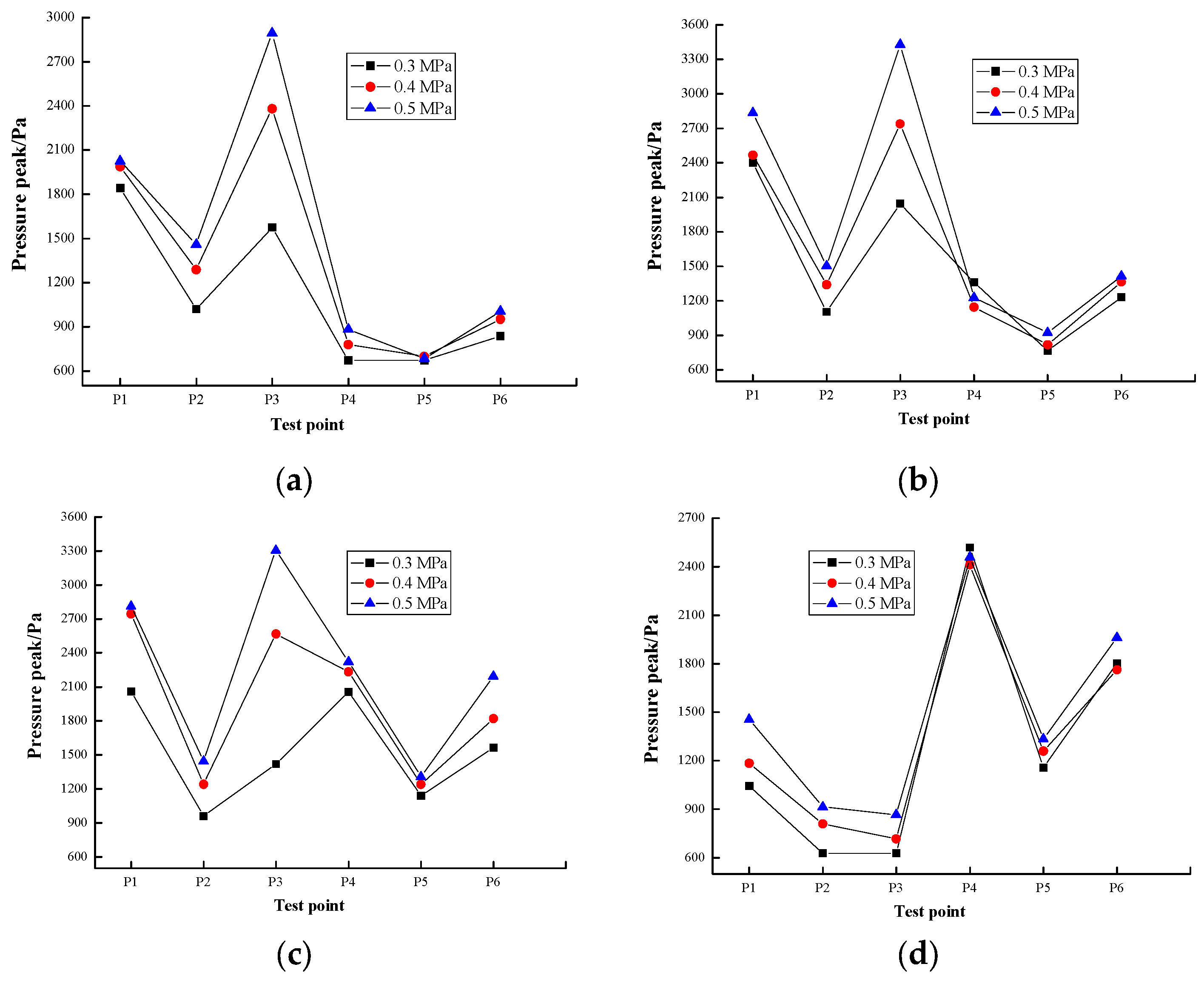
2.3.2. Effect of Pulse Pressure on Peak Pressure of Flat Cartridge

Increasing the pulse pressure is the most effective means to improve the cleaning performance of the flat cartridge [28,29]. In order to further analyze the effects of the nozzles with different areas on the peak pressure of the flat cartridge at different pulse pressures. Figure 5 shows the change of pressure at the nozzles with different total nozzle areas at different pulse pressures at the jet distance of 20 mm.
Table 4 shows the peak pressure distribution law at the nozzles with different pulse pressures and the Pc was calculated. The results are provided in Table 5.
It can be seen from Figure 5 that, with increasing pulse pressure, the peak pressure at all points increased to varying degrees and the maximum peak pressure only at the opposite nozzles increased. Therefore, the low pulse pressure was more favorable to the cleaning uniformity at required cleaning performance. However, when the integrated pressure Pc was used to judge the cleaning effect, it did not meet the requirements of the uniformity of the cleaning. Because the pulse pressure changes the flow of the airflow, increasing the overall pressure, that is, the literature [26] can only evaluate the ash cleaning performance of the same air flow rate, and is not suitable for the flow rate to be changed. The cleaning performance for changes in airflow can only be evaluated by AP and RSD [10,13,23].
It can be found from Table 4 that, with increasing pulse pressure, both the AP and RSD of the nozzles with total nozzle areas of 273, 546, and 819 mm2 increased slowly, and the AP and RSD of the nozzle with a total nozzle area of 1365 mm2 increased and decreased, respectively. With increasing total nozzle area at constant pulse pressure, both the AP and RSD of the nozzles first increased and then decreased. This proves that the nozzle with a total nozzle area of 1365 mm2 had the worst cleaning performance and thus will not be taken into account in the subsequent industrial dust test. In addition, it can be seen that, with increasing nozzle area at constant pulse pressure, the peak pressure at the non-positive nozzles increased significantly. Therefore, increasing the total nozzle area can increase the peak pressure of the flat cartridge to a certain extent, and thus can solve the problem of different pressure distribution between opposite nozzles and non-positive nozzles. Better conditions should be obtained according to the industrial dust experimental results.

3. Industrial Dust Experiment

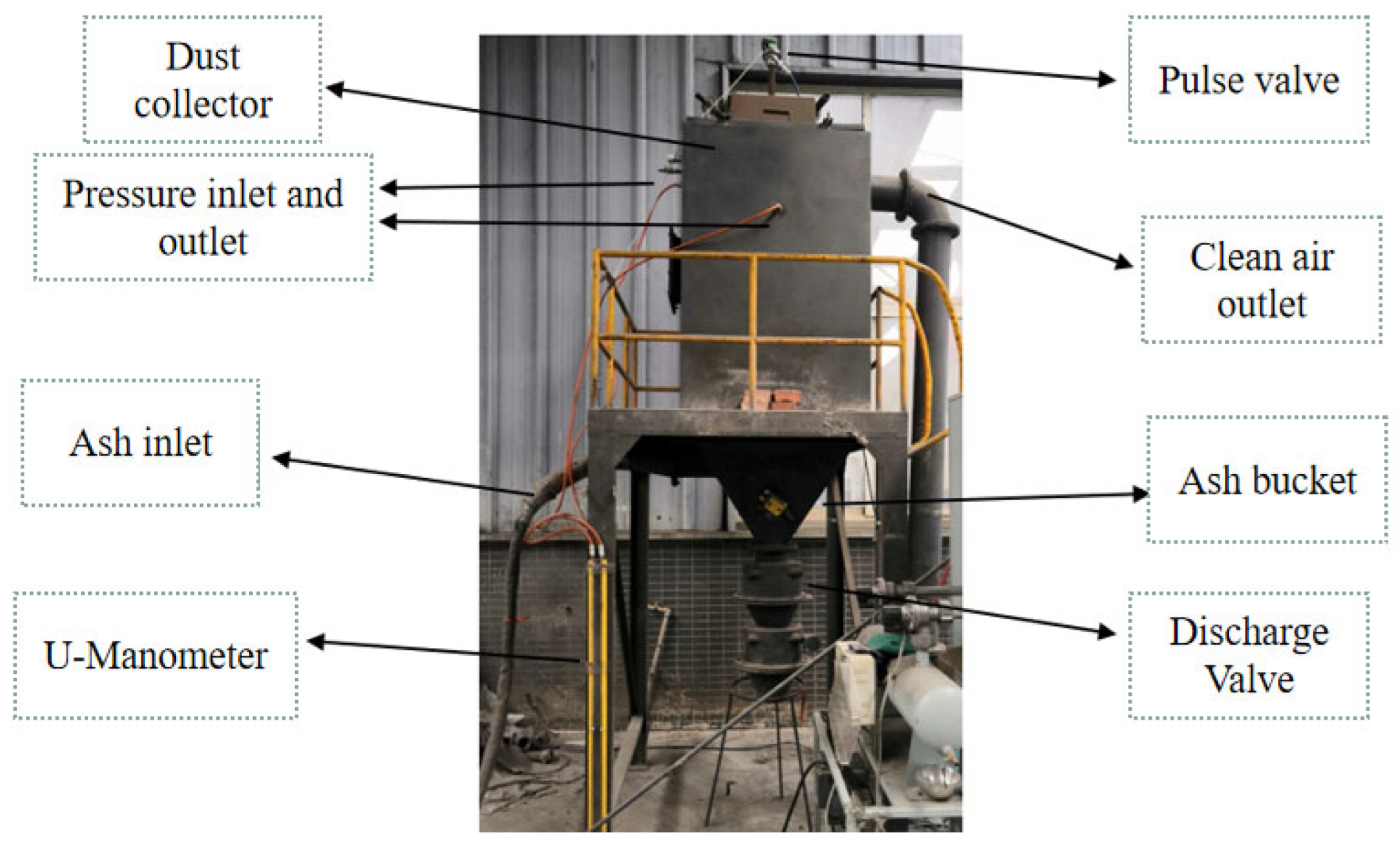
3.1. Experimental Equipment and Parameters

To evaluate the rationality of using integrated pressure to evaluate the effect of dust cleaning, it was verified using an industrial dust experiment. The industrial dust test system consisted of a dust collector, DMF-ZM-25 1” pulse valve, discharge valve, ash bucket and U-manometer, as shown in Figure 6.
The pulverized fuel ash (D50 = 11.87 μm) was selected for the dust test. A U-manometer was connected to the inlet and outlet of the dust collector, respectively, to test the operation resistance of the cleaning system [30]. The dust was collected at a regular time online during the test under the operation conditions as shown in Table 6.

3.2. Experimental Method

The experiment was carried out at varying pulse pressure and distance at a constant ratio of gas and solid. In the experiment, the readings on the U-manometers were reported every 5 min. The readings indicated the operation resistance of the cleaning system. After 60 min operation, the pulse controller was stopped, and the pressure valve was closed before the cartridge was taken out and weighed. The dust residue is the difference in the cartridge weight before and after the operation, and the system operation resistance difference is the system resistance difference before and after the operation.

3.3. Result and Discussion

Figure 7 shows the change in the system operation resistance of the flat cartridge with different nozzle areas and different jet distances at the pulse pressure of 0.3 MPa.
It shows that the flat cartridge has small system operation resistance, not more than 350 Pa. It can also be seen from Figure 7a that the cartridge had the lowest operation resistance at the jet distance of 40 mm and the operation resistance of the cartridge plateaus within 45 min at different jet distances. At the jet distance of 10 mm, the system operation resistance was large and rising. According to the pulse jet test results, P4 had low peak pressure at the jet distance of 10 mm, so the cleaning uniformity was poor.
Figure 7b shows that at the jet distance of 40 mm, the cartridge had the lowest system operation resistance and reached a stable state in 25 min, a shorter time than the cartridge with a total nozzle area of 273 mm2. At the jet distances of 10, 80 and 100 mm, the system operation resistance was large and rising. The pulse jet test results show that, at the jet distance of 10 mm, P4 did not reach the required cleaning performance, so the system operation resistance increased. At the jet distance of 80 and 100 mm, the peak pressure of the opposite nozzles decreased rapidly, while the peak pressure of the non-positive nozzle led to uneven cleaning and thus increased the system operation resistance.
It can be seen from Figure 7c that the flat cartridge had the smallest system operation resistance at the jet distance of 10~20 mm, and the system operation resistance gradually plateaued within 25 min. The flat cartridge had the highest system operation resistance at the jet distance of 80 and 100 mm. The pulse jet test results show that, at the jet distance of 80 and 100 mm, the peak pressure at the opposite nozzles was much smaller than that at the non-positive nozzles, resulting in uneven cleaning of the flat cartridge.
The cleaning effects of the cartridge with different nozzles at different total nozzle areas at different jet distances were further explored according to the dust residue and the system operation resistance difference before and after the operation time of 60 min.
Figure 8 and Figure 9 show the system operation resistance difference and dust residue of the cartridge with different nozzle areas and different jet distances at the pulse pressure of 0.3 MPa, respectively.
It can be seen from Figure 8 and Figure 9 that the system operation resistance difference and dust residue of the flat cartridge changed roughly in the same law at the pulse pressure of 0.3 MPa. The flat cartridge, with a total nozzle area of 273, 546, and 819 mm2, had the smallest dust residue and system resistance difference and the best cleaning effect at the jet distance of 40, 20~40 and 20 mm, respectively, which was generally consistent with the pulse jet test results.
Figure 10 shows the change of system resistance at different nozzle areas and different jet distances at the pulse pressure of 0.4 MPa.
Figure 10a,b indicate that the cartridge with a total nozzle area of 273, 546, and 819 mm2 had the smallest system operation resistance and the best cleaning effect at the jet distance of 40, 20~40, and 20 mm, respectively.
Figure 11 and Figure 12 show the system resistance difference and dust residue of the nozzles with different areas at different jet distances at the pulse pressure of 0.4 MPa, respectively.
It can be seen from Figure 8, Figure 9, Figure 11 and Figure 12 that. with increasing pulse pressure, both the system resistance difference and dust residue of the flat cartridge decreased. The optimal jet distance at different nozzle areas at the pulse pressure of 0.4 MPa was consistent with the experimental results at 0.3 MPa.
The accuracy of the experimental results of the pulse jet was verified by the industrial dust, and it also showed that Pc can be applied to the evaluation of the cleaning performance of the same airflow.

4. Conclusions

(1)
The effects of slot-type nozzle area on the cleaning effect of the flat cartridge were studied by pulse jet test. With increasing slot-type nozzle area, the peak pressure at the non-positive nozzles increased, and the peak pressure at the opposite nozzles first increased and then decreased. Therefore, increasing the area of the slot-type nozzle at a certain pulse pressure can improve the peak pressure of the non-positive nozzles of flat cartridges to a certain extent and solve the problem of uneven cleaning of the flat cartridge.
(2)
Experimental results indicate that the integrated pressure is a valid and reliable index for evaluating the dust-cleaning effect of a pulse-jet cartridge filter in the same airflow.
(3)
With increasing pulse pressure, the average peak pressure of the flat cartridge increased, but the pressure distribution uniformity decreased. The industrial dust and pulse cleaning experiments show that the cleaning performance can be reached at the pulse pressure of 0.3 MPa. Thus, the optimal pressure was 0.3 MPa in this experiment.
(4)
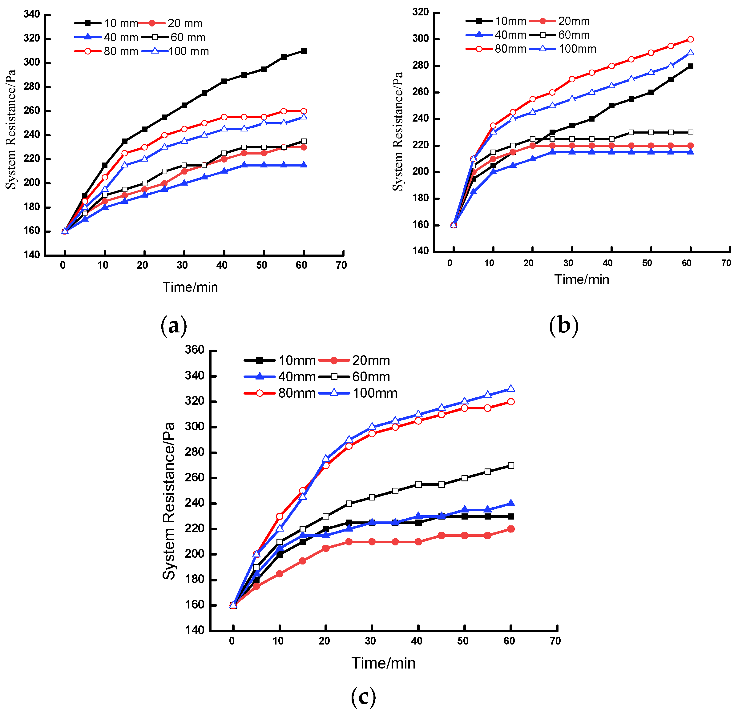
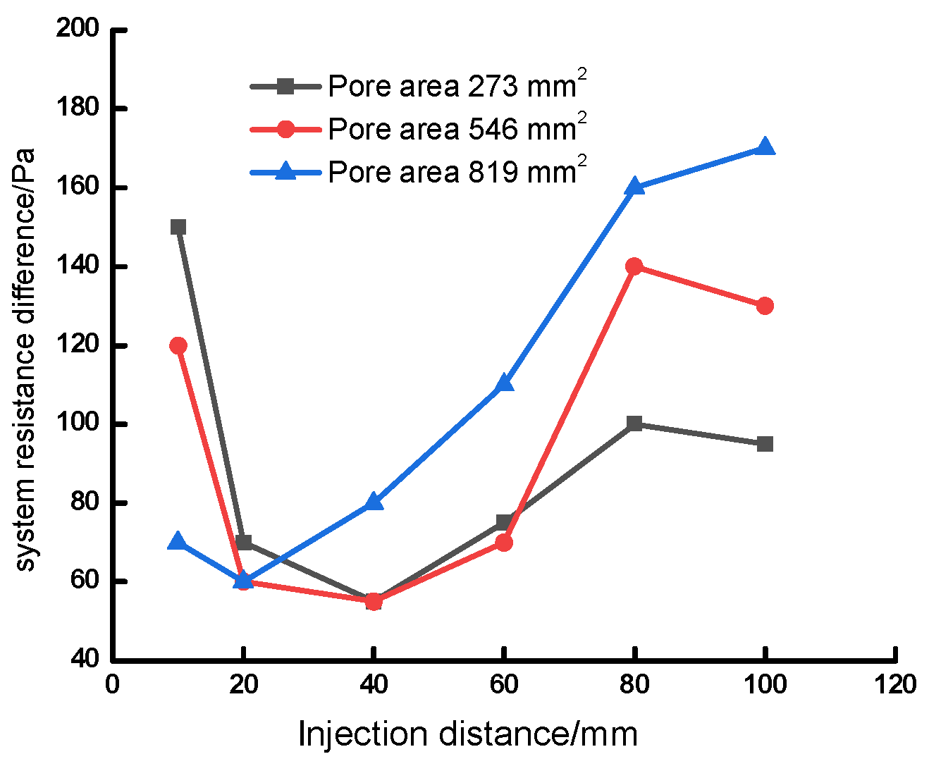
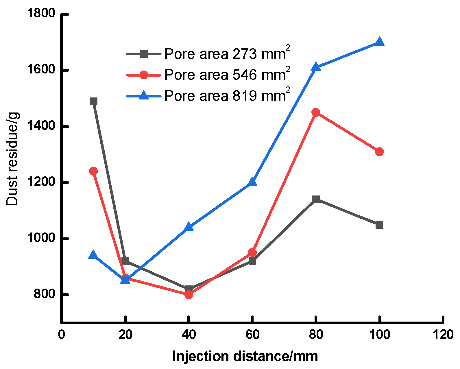
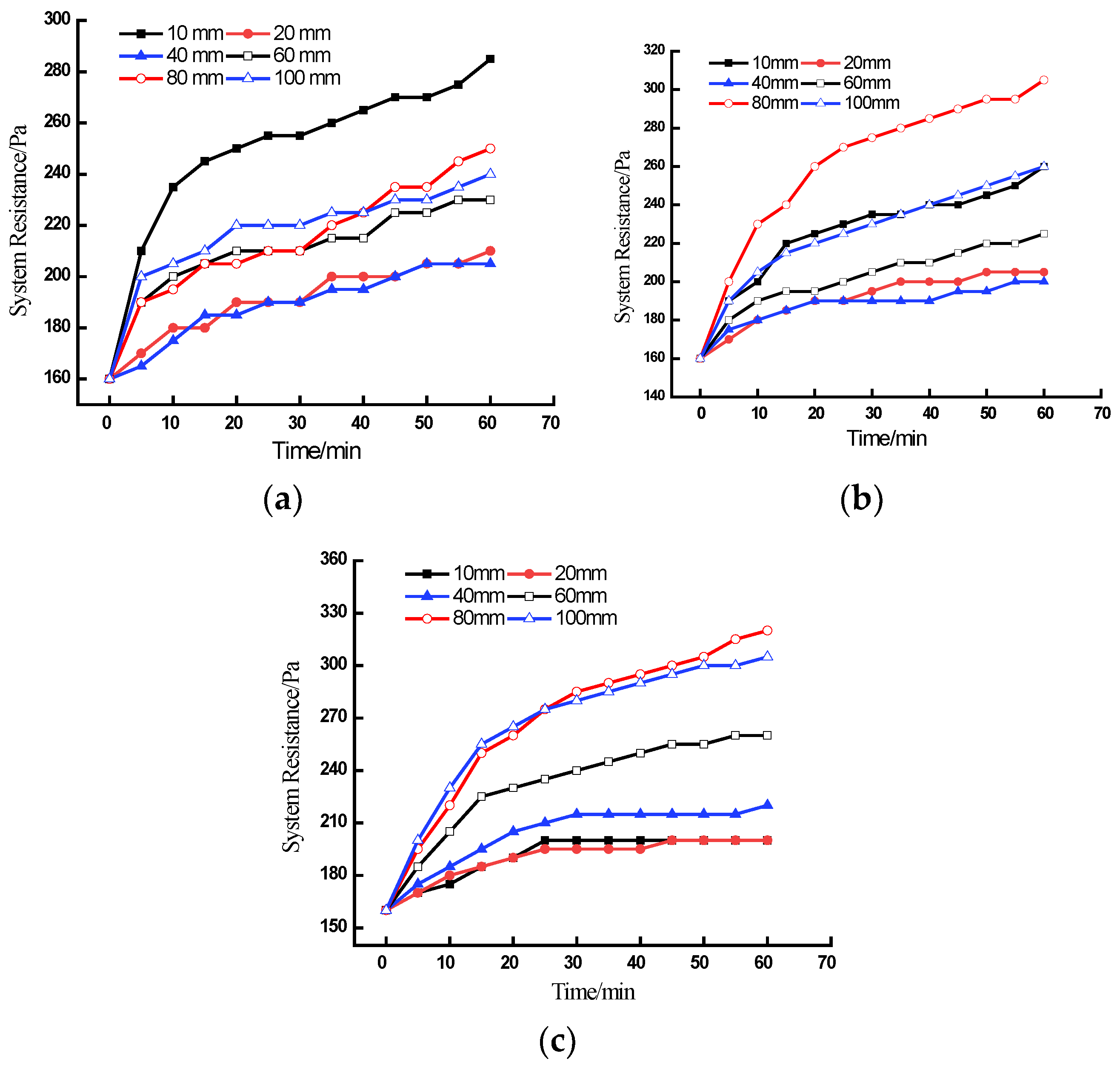
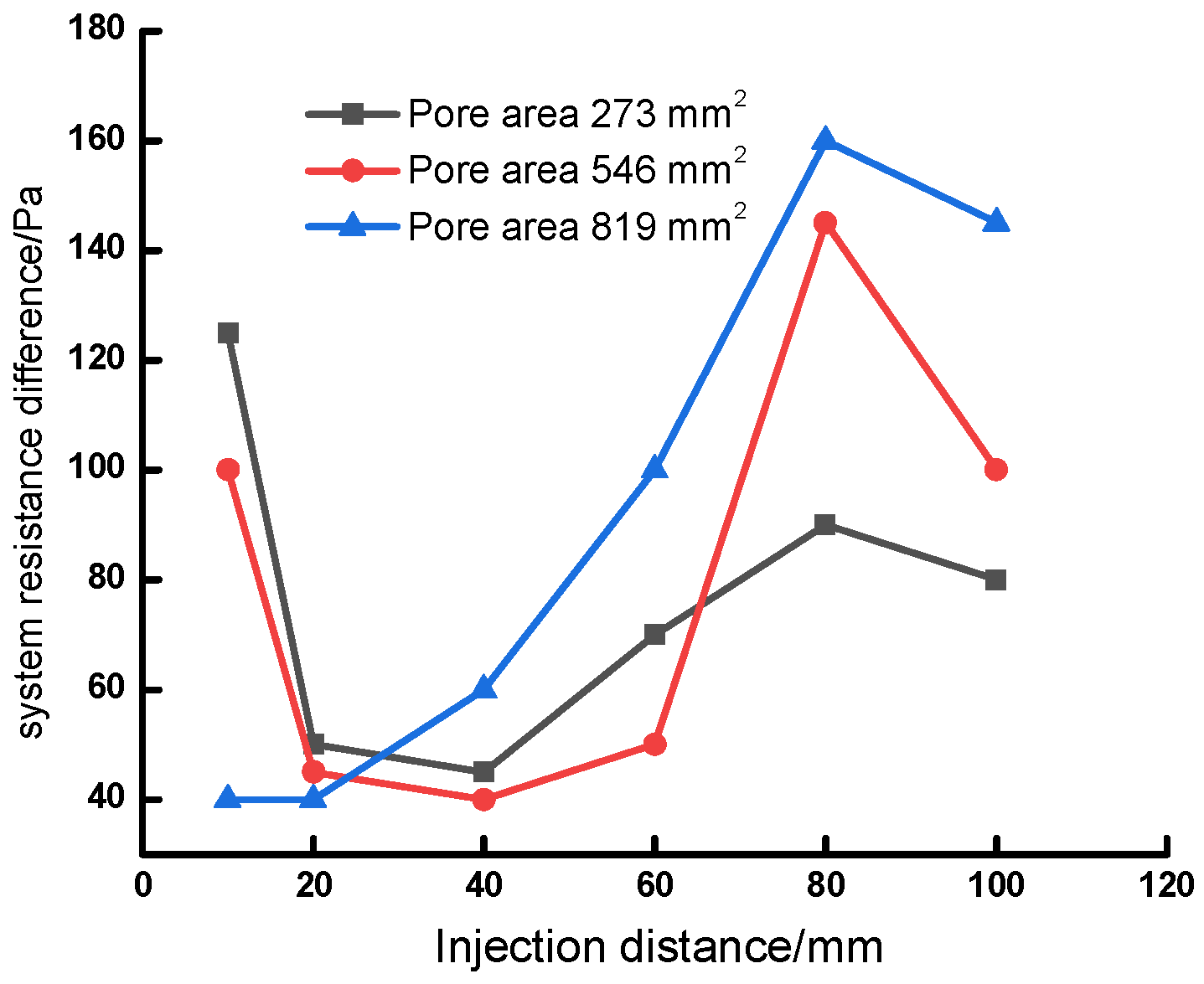
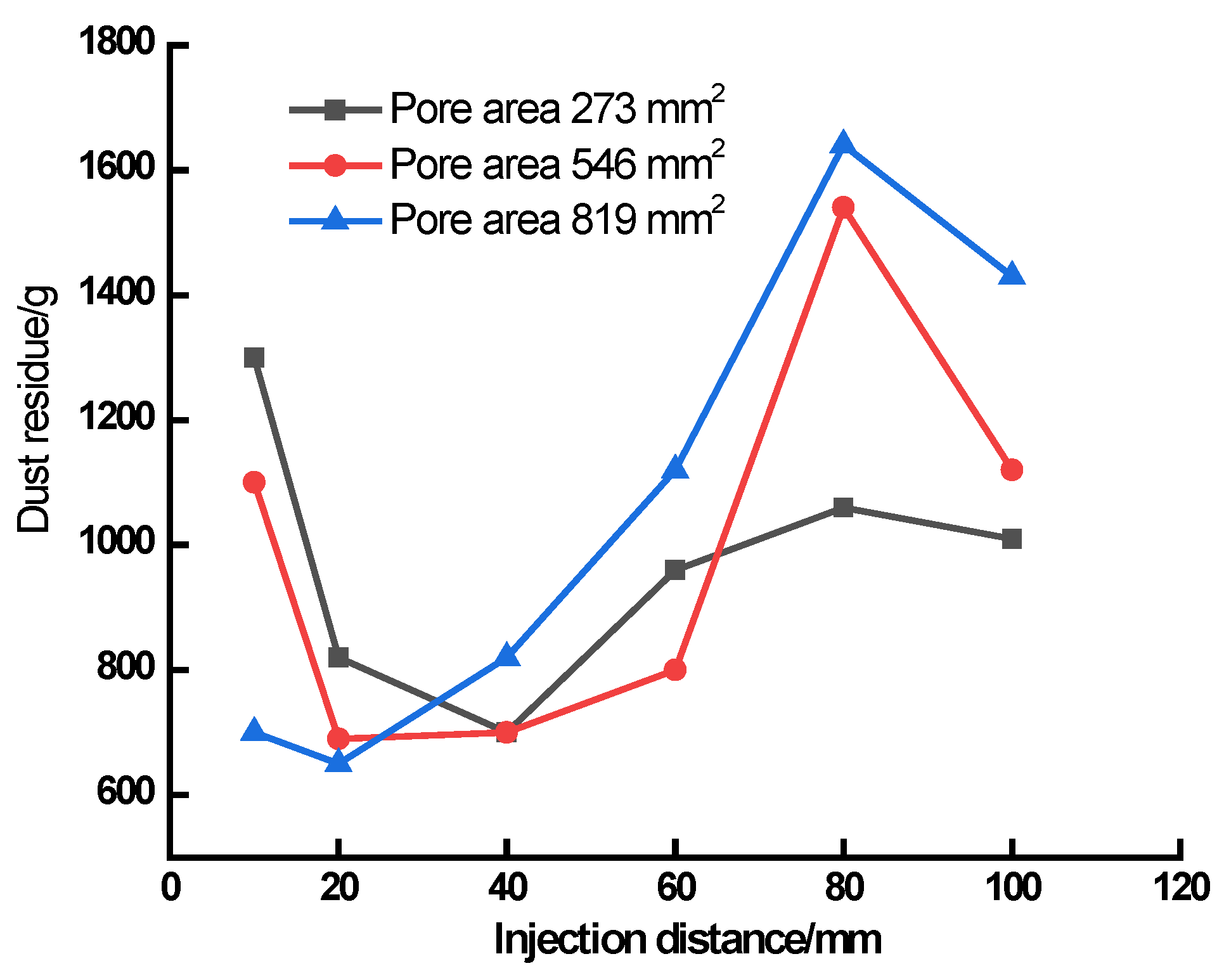
The flat cartridge with the slot-type nozzles with a total nozzle area of 819 mm2 offered better cleaning performance than that of 273 and 546 mm2, while the cleaning performance became worse when the total nozzle area increased to 1365 mm2. Under the premise of meeting the requirement of dust removal, the optimal jet distance decreased with the increase in the nozzle area. The industrial dust and pulse cleaning experiments showed the flat cartridge with a total nozzle area of 273, 546 and 819 mm2 showed the smallest dust residue and running resistance and the best cleaning effect at the jet distance of 40, 20~40 and 20 mm, respectively.
(5)
The above results showed that a good deashing performance can be obtained for the flat cartridge used in this work by the slot-type nozzle with a total nozzle area below 819 mm2. However, a bad deashing performance was caused by a larger total nozzle area (such as 1365 mm2), indicating that this large total nozzle area was not suitable for the cartridge used in this work. In future studies, for larger precipitators, whether a larger total nozzle area (such as 1365 mm2 or larger) can lead to a good deashing performance should be studied.

Author Contributions

Conceptualization, H.C. (Haiyan Chen).; methodology, H.C. (Huan Cheng).; formal analysis, X.L.; investigation, X.L.; writing—original draft preparation, X.L. and J.L.; writing—review and editing, J.L.; supervision, Z.X. All authors have read and agreed to the published version of the manuscript.

Funding

This research received no external funding.

Institutional Review Board Statement

Not applicable.

Informed Consent Statement

Not applicable.

Data Availability Statement

Not applicable.

Acknowledgments

The authors are grateful to the reviewers who help them improve the paper with many pertinent comments and suggestions.

Conflicts of Interest

The authors declare no conflict of interest.

References

  1. Zhang, Y.; Chen, H.; Zhu, Q. Current situation of cartridge dust collector and its application. Energy Environ. 2009, 5, 47–52. [Google Scholar]
  2. Yuan, Z.; Khakzad, N.; Khan, F.; Amyotte, P. Dust explosions: A threat to the process industries. Process Saf. Environ. Prot. 2015, 98, 57–71. [Google Scholar] [CrossRef]
  3. Qin, J.; Ji, X. Application of filter cartridge dust collector in cement industry. Inn. Mong. Petrochem. Ind. 2011, 8, 116–117. (In Chinese) [Google Scholar]
  4. Yan, C.; Zhang, M.; Lin, L.; Chen, H. An analysis of a reverse pulse cleaning process using high-flow pleated fabric filter cartridges. Process Saf. Environ. Prot. 2018, 113, 264–274. [Google Scholar]
  5. Qian, Y.; Chen, H.; Dai, H.; Liu, T.; Kuang, T.; Bian, L. Experimental study of the nozzle settings on blow tube in a pulse-jet cartridge filter. Sep. Purif. Technol. 2017, 191, 244–249. [Google Scholar] [CrossRef]
  6. Li, J.; Wu, D.; Wu, Q.; Luo, M.; Li, J. Design and performance evaluation of novel colliding pulse jet for dust filter cleaning. Sep. Purif. Technol. 2019, 213, 101–113. [Google Scholar] [CrossRef]
  7. Yuan, N.; Ren, L.; Wang, B.; Teng, D.; Li, P.; Xu, Z.; Li, Y.; Chen, H.; Lin, L. Experimental study on the effects of diversion device on pulse-jet cleaning of horizontal filter cartridge. Process Saf. Environ. Prot. 2021, 145, 247–254. [Google Scholar] [CrossRef]
  8. Ellenbecker, M.J.; Leith, D. Dust removal from nonwoven fabrics—Cleaning methods need to be improved. Filtr. Sep. 1981, 18, 316–320. [Google Scholar]
  9. Zhang, M.; Chen, H.; Yan, C.; Li, Q.; Qiu, J. Investigation to rectangular flat pleated filter for collecting corn straw particles during pulse cleaning. Adv. Powder Technol. 2018, 29, 1787–1794. [Google Scholar] [CrossRef]
  10. Li, Q.; Zhang, M.; Qian, Y.; Geng, F.; Song, J.; Chen, H. The relationship between peak pressure and residual dust of a pulse-jet cartridge filter. Powder Technol. 2015, 283, 302–307. [Google Scholar] [CrossRef]
  11. Chen, S.; Chen, D.R. Annular-slit nozzles for reverse flow cleaning of pleated filter cartridges. Sep. Purif. Technol. 2017, 177, 182–191. [Google Scholar] [CrossRef]
  12. Shim, J.; Joe, Y.H.; Park, H.S. Influence of air injection nozzles on filter cleaning performance of pulse-jet bag filter. Powder Technol. 2017, 322, 250–257. [Google Scholar] [CrossRef]
  13. Li, S.; Zhou, F.; Xie, B.; Wang, F. Influence of injection pipe characteristics on pulse-jet cleaning uniformity in a pleated cartridge filter. Powder Technol. 2018, 328, 264–274. [Google Scholar] [CrossRef]
  14. Yan, C.; Liu, G.; Chen, H. Effect of induced airflow on the surface static pressure of pleated fabric filter cartridges during pulse jet cleaning. Powder Technol. 2013, 249, 424–430. [Google Scholar] [CrossRef]
  15. Qian, Y.; Bi, Y.; Zhang, M.; Bi, Y.; Xu, G. Effect of filtration operation and surface treatment on pulse-jet cleaning performance of filter bags. Powder Technol. 2015, 277, 82–88. [Google Scholar] [CrossRef]
  16. Andersen, B.O.; Nielsen, N.F.; Walther, J.H. Numerical and experimental study of pulse-jet cleaning in fabric filters. Powder Technol. 2016, 291, 284–298. [Google Scholar] [CrossRef]
  17. Sievert, J.; Loffler, F. Fabric cleaning in pulse-jet filters. Chem. Eng. Process. Process Intensif. 1989, 26, 179–183. [Google Scholar] [CrossRef]
  18. Li, J.; Li, S.; Zhou, F. Effect of cone installation in a pleated filter cartridge during pulse-jet cleaning. Powder Technol. 2015, 284, 245–252. [Google Scholar] [CrossRef]
  19. Hu, S.; Li, S.; Jin, H.; Xie, B.; Liu, H.; Tan, X.; Zhou, F. Study of a new type slit injection pipe on pulse cleaning performance to the rectangular flat pleated filter. Powder Technol. 2021, 394, 459–467. [Google Scholar] [CrossRef]
  20. Kang, F.; Cheng, H.; Leng, H.; Zen, S.; Chen, H. Performance optimization of rectangular flat pleated filter with slit nozzle for dust cleaning. Powder Technol. 2020, 376, 320–331. [Google Scholar] [CrossRef]
  21. Cheng, H.; Yang, T.; Cui, S.; Xu, Z.; Leng, H.; Qian, Y.; Lin, L.; Chen, H. Effect of slot-type nozzles on cleaning performance of flat filter cartridge. China Powder Sci. Technol. 2022, 28, 68–76. (In Chinese) [Google Scholar]
  22. Mahmood, S.; Gernot, K. Effect of filtration velocity and dust concentration on cake formation and filter operation in a pilot scale jet pulsed bag filter. J. Hazard. Mater. 2007, 144, 677–681. [Google Scholar]
  23. Huang, M.; Yan, C.; He, C.; Tang, C.; Yang, F.; Li, P. The relationship between peak pressure and parameters of pulse-jet cleaning in a sintered plastic filter. J. Air Waste Manag. Assoc. 2021, 71, 1055–1066. [Google Scholar] [CrossRef] [PubMed]
  24. Lin, L.; Liu, T.; Yuan, N.; Xu, Z.; Chen, H. Study on the influence of venturi on the cleaning performance of elliptical filter cartridge. Powder Technol. 2021, 377, 139–148. [Google Scholar] [CrossRef]
  25. Lu, H.; Tsai, C. A pilot-scale study of the design and operation parameters of a pulse-jet baghouse. Aerosol Sci. Technol. 1998, 29, 1079–1080. [Google Scholar] [CrossRef]
  26. Lu, H.; Tsai, C. Influence of design and operation parameters on bag-cleaning performance of pulse-jet baghouse. J. Environ. Eng. 1999, 125, 583–591. [Google Scholar] [CrossRef]
  27. Zhang, Q.; Liu, D.; Wang, M.; Shu, Y.; Xu, H.; Chen, H. Characteristics and evaluation index of pulse-jet dust cleaning of filter cartridge. Process Saf. Environ. Prot. 2021, 157, 362–374. [Google Scholar] [CrossRef]
  28. Kim, J.; Lee, M. Measurement of effective filtration area of pleated bag filter for pulse-jet cleaning. Powder Technol. 2019, 343, 662–670. [Google Scholar] [CrossRef]
  29. Li, S.; Xin, J.; Xie, B.; Jin, H.; Hu, S.; Song, S.; Zhou, S.; Zhou, F. Experimental investigation of the optimization of nozzles under an injection pipe in a pulse-jet cartridge filter. Powder Technol. 2019, 345, 363–369. [Google Scholar] [CrossRef]
  30. Furumoto, K.; Narita, T.; Fukasawa, T.; Ishigami, T.; Kuo, H.; Huang, A.; Fukui, K. Influence of pulse-jet cleaning interval on performance of compact dust collector with pleated filter. Sep. Purif. Technol. 2021, 279, 119688. [Google Scholar] [CrossRef]
Figure 1. Schematic diagram of the flat filter cartridge positive and non-positive pulse airflow.
Atmosphere 14 00325 g001
Figure 2. Schematic diagram of the pulse-jet experimental equipment.
Atmosphere 14 00325 g002
Figure 3. Pressure points with positive and non-positive pulse airflow.
Atmosphere 14 00325 g003
Figure 4. The change of the peak pressure on the sidewalls with different nozzle areas at different jet distances at the pulse pressure of 0.3 MPa. (a) Total nozzle area of 273 mm2. (b) Total nozzle area of 546 mm2. (c) Total nozzle area of 819 mm2. (d) Total nozzle area of 1365 mm2.
Atmosphere 14 00325 g004
Figure 5. The change of the peak pressure on the sidewalls with different nozzle areas under different injection pressures. (a) Total nozzle area of 273 mm2. (b) Total nozzle area of 546 mm2. (c) Total nozzle area of 819 mm2. (d) Total nozzle area of 1365 mm2.
Atmosphere 14 00325 g005
Figure 6. Industrial dust experiment platform.
Atmosphere 14 00325 g006
Figure 7. The change in the system operation resistance of the flat cartridge with different nozzle areas and different jet distances at the pulse pressure of 0.3 MPa. (a) Total nozzle area of 273 mm2. (b) Total nozzle area of 546 mm2. (c) Total nozzle area of 819 mm2.
Atmosphere 14 00325 g007
Figure 8. The system operation resistance difference of the cartridge with different.
Atmosphere 14 00325 g008
Figure 9. The dust residue of the cartridge with different nozzle areas and different jet distances at the pulse pressure of 0.3 MPa.
Atmosphere 14 00325 g009
Figure 10. The change in the system operation resistance of the flat cartridge with different nozzle areas and different jet distances at the pulse pressure of 0.4 MPa. (a) Total nozzle area of 273 mm2. (b) Total nozzle area of 546 mm2. (c) Total nozzle area of 819 mm2.
Atmosphere 14 00325 g010
Figure 11. The system operation resistance difference of the cartridge with different nozzle areas and different jet distances at the pulse pressure of 0.4 MPa.
Atmosphere 14 00325 g011
Figure 12. The dust residue of the cartridge with different nozzle areas and different jet distances at the pulse pressure of 0.4 MPa.
Atmosphere 14 00325 g012
Table 1. Parameter settings of the deashing process for the four kinds of slot-type nozzles with different nozzle areas.
FactorLevel
Pulse pressure (MPa)0.3, 0.4, 0.5
Jet distance (mm)10, 20, 40, 60, 80, 100
Pulse Width (ms)80
Table 2. The average pressure and relative standard deviation of pressure at the total nozzle areas of different nozzles.
Jet Distance (mm)Sidewall Pressure Peaks with the Total Nozzle Areas of 273 mm2Sidewall Pressure Peaks with the Total Nozzle Areas of 546 mm2Sidewall Pressure Peaks with the Total Nozzle Areas of 819 mm2Sidewall Pressure Peaks with the Total Nozzle Areas of 1365 mm2
AP/PaRSDAP/PaRSDAP/PaRSDAP/PaRSD
109820.58312760.57315940.38613280.398
2011020.44814850.41515340.29812970.569
4013140.38715290.29212300.34516640.533
6011320.34412750.33713890.54713550.466
809320.33312420.40614330.4789400.481
1008930.28413050.49614630.3308400.580
Table 3. Integrated pressure.
Jet Distance (mm)1020406080100
Total Nozzle Areas (mm2)
273598.87827.621066.94947.75777.54728.78
546842.931140.201186.111070.49992.99989.82
8191261.541201.731028.62920.09979.511185.63
13651071.50925.241097.001017.37721.95555.66
Table 4. The peak pressure distribution law at the nozzles with different pulse pressures.
Pulse Pressure (mm)Sidewall Pressure Peaks with the Total Nozzle Areas of 273 mm2Sidewall Pressure Peaks with the Total Nozzle Areas of 546 mm2Sidewall Pressure Peaks with the Total Nozzle Areas of 819 mm2Sidewall Pressure Peaks with the Total Nozzle Areas of 1365 mm2
AP/PaRSDAP/PaRSDAP/PaRSDAP/PaRSD
0.311020.44814850.41515340.29812970.569
0.413480.51216460.46819750.32913570.469
0.514920.56218890.52922310.34614980.412
Table 5. The integrated pressure at the nozzles with different pulse pressures.
Pulse Pressure (MPa)0.30.40.5
Total Nozzle Areas (mm2)
273827.62964.061073.92
5461140.201192.671347.20
8191201.731517.461769.47
1365925.241037.331167.72
Table 6. Experimental design parameters of the industrial dust test system.
ParametersSetting
Mass concentration of gas to solid (g·m−3)35
Filtration velocity (m·min−1)0.6
Pulse pressure (MPa)0.3, 0.4
Pulse width (ms)80
Pulse interval (s)60
Total nozzle area (mm2)273, 546 and 819
Intake typeLower air inlet
Disclaimer/Publisher’s Note: The statements, opinions and data contained in all publications are solely those of the individual author(s) and contributor(s) and not of MDPI and/or the editor(s). MDPI and/or the editor(s) disclaim responsibility for any injury to people or property resulting from any ideas, methods, instructions or products referred to in the content.

