1. Introduction
For hazard assessment purposes, the dispersion of gases in complex urban areas is often a scenario to be considered. However, predicting the dispersion of heavy gases is still a subject of ongoing research. The model used should not only be able to predict the near-ground atmospheric boundary layer flow correctly, but it should also be able to account for obstacles in the flow domain, as they have a relevant impact on the (heavy) gas dispersion.
While meteorological models predict the wind field for larger scales in the range of kilometers, smaller scales, in the range of a few hundreds of meters, are of interest for hazard assessment purposes. Therefore, even smaller obstacles can have a significant effect on the gas dispersion and must be considered. Besides the atmospheric wind field, the heavy gas effects play a major role for heavy gas dispersion, especially the damping of the atmospheric turbulence at the top of the heavy gas cloud. Herein, the density gradient is the variable of interest. Due to negative buoyant forces in the heavy gas cloud, the dispersion will be focused near the ground, so that obstacles must be resolved in a satisfactory manner to account for their influence on the gas dispersion.
The prediction of the hazardous areas due to the dispersion of accidental gas releases is usually done in Germany using the VDI Guideline 3783/1 and 3783/2 [
1,
2]. While VDI 3783/1 uses a gaussian approach to model the dispersion of light and neutrally buoyant gases, VDI 3783/2, based on wind tunnel experiments, is used to predict the dispersion of heavy gases. These wind tunnel experiments are transferred to real scale releases through the application of dimensional analysis relations. With a reduced set of input values (density of the gas, mass flow, release duration), a quick estimation of the lower flammability distance can be achieved. Nevertheless, this quick and easy approach is subject to several restrictions. The VDI 3783/2 is based on the work of [
3,
4], who investigated the heavy gas dispersion out of a low momentum ground source in a wind tunnel for 25 generic obstacle configurations, so called dispersion area types, ranging from flat and obstacle-free terrain to multi-obstacle configurations. The latter are always a set of regularly distributed and shaped (generally cubic shaped) obstacles, geometrically defined by means of a characteristic length scale. It is very often impossible to represent the existing real built-up situation with one of these generic dispersion area types. In addition, the wind speed is not a user-defined boundary condition but is implicitly assumed as a characteristic wind speed scale. Sources located above the ground cannot be taken into account (e.g., gas release on the roof of a building or out of a window), making it impossible to predict to what extent the cloud would be diluted on its way to the ground.
To overcome these restrictions, CFD methods seem a promising alternative. By solving the full Navier–Stokes equations, CFD codes can simultaneously model the wind field and the dispersion of pollutants, taking into account obstacles, topography, thermal stratification as well as the type of release (with or without momentum). Generally, to achieve a satisfying cost–benefit ratio, CFD codes are used relying on RANS (Reynolds-averaged Navier–Stokes) equations. To close the RANS equations, the k-ε turbulence model is used to calculate the atmospheric wind field in a wide number of publications.
The use of RANS comes with some practical issues. For simulation of the heavy gas dispersion, a model should predict the near-ground atmospheric boundary layer flow and the heavy gas effects correctly. The approach flow has a relevant effect on the gas dispersion and the hazardous areas [
5]. To simulate an atmospheric boundary layer flow, it is necessary to achieve a horizontally homogenous approach flow that conserves the atmospheric inflow boundary condition from the inlet until the source or the first obstacle [
6]. Therefore, consistency between the inlet boundary conditions with the turbulence model and the wall functions at the ground, resulting in a horizontally homogenous boundary layer flow (HHBLF), is required [
6]. For incompressible solvers and neutral temperature stratification of the atmosphere, adapted boundary conditions and wall functions can be used [
6]. For a compressible solver or for stable or unstable temperature stratification of the atmosphere, additional modifications of the k-ε turbulence model are necessary. Refs. [
7,
8] investigated stable and unstable temperature stratification of the atmosphere and introduced additional source terms for the turbulence model to achieve a HHBLF. These approaches are based on the Monin–Obukhov Similarity Theory (MOST) for the inlet wind profiles, using the log wind profile dependent on the height and the roughness length
. The authors of [
9] showed that using a logarithmic wind profile for a HHBLF requires the first ground adjacent cell size to be at least two times larger than the ground roughness. This is in contradiction with the aim of simulating near-ground gas dispersion, as the ground-adjacent cells would be too large for higher roughness lengths to resolve the gas cloud and smaller obstacles in a satisfactory manner. Ref. [
10] presented A CFD model, based on a compressible solver of the open source CFD code OpenFOAM, able to compute a HHBLF while overcoming the wall resolution restrictions due to the roughness length at the wall. The wind profile is described by a power law instead of a log law. The validation of this model against wind tunnel experiments [
11,
12] showed a good agreement of the model predictions with the experimental data.
Many publications dealing with heavy gas dispersion do concentrate on specific aspects of single experiments (e.g., [
13,
14,
15,
16,
17]). Nevertheless, in these publications, the atmospheric boundary layer flow is either not mentioned or considered, or it is solved using the approach based on
. For the aim of simulating near-ground heavy gas dispersion in an atmospheric boundary layer flow with a satisfactory resolution, these approaches do not seem adequate.
This work presents an approach to simulate near-ground heavy gas dispersions in a built-up environment with OpenFOAM, based on the HHBLF-model of [
10] with additional modifications taking into account heavy gas effects, especially the damping of the turbulent species transport at the top of the heavy gas cloud. To validate the model, a set of specific experiments were carried out in a wind tunnel for realistic built-up scenarios for near-ground heavy gas dispersion. In addition to variations of the inflow angle, the source location was also varied from ground sources to vertical sources up to elevated sources (on the roof of a building).
2. A Modified Turbulence Model and Species Transport Equation for Heavy Gas Dispersion
Atmospheric gas dispersion strongly depends on the wind field transporting the pollutant. When simulating the gas dispersion under atmospheric conditions, special attention has to be paid to the quality of the wind field prediction, as it has a direct influence on the quality of the gas dispersion prediction. Therefore, the model presented here shows modifications to account for heavy gas effects and incorporates the wind field model of [
10] in order to achieve an atmospheric boundary layer flow.
2.1. Wind Field Modelling
The presented CFD model is based on the transient and compressible solver
rhoReactingBuoyantFoam [
18,
19], as well as on the
k-ε-turbulence model of Launder and Spalding [
20] and El Tahry [
21] implemented in OpenFOAM 5.0. The governing transport equations describing the turbulent kinetic energy
k (1) and the dissipation
ε (2) are coupled to the Navier–Stokes equations through the turbulent viscosity
νt (3):
Herein,
ρ is the density,
t the time,
uj the velocity component in
xj direction,
μ the dynamic viscosity,
μt the turbulent dynamic viscosity and
Pk the turbulence production. The values of the model constants
C1, C2, Cμ, σk and
σε in Equations (1)–(3) are based on [
22]. In (2), an additional source term
Sε, was introduced to achieve horizontal homogeneity of the incident atmospheric boundary layer flow. This term is time-independent as it is evaluated solely at the beginning of the simulation based on the vertical inlet profiles depending on the height
z. As it was introduced to influence the incident flow, the term is only active in the upstream region when simulating obstacles in the domain. Near obstacles, the turbulence model is used with
Sε = 0.
The source term Sε is designed to compensate the expected dissipation of turbulent kinetic energy that would occur when using the standard k-ε-model in an obstacle-free flow domain. In the OpenFOAM k-ε-turbulence model, the turbulence production due to buoyancy effects is generally not considered Gb,k = Gb,ϵ = 0.
As stated in [
10], the modification to the turbulence model requires adapted boundary conditions for the vertical profiles of the velocity in main direction
Ux, the turbulent kinetic energy
k and dissipation ε. For a neutral temperature stratification in the atmosphere, the inlet boundary conditions are dependent on the reference velocity
Uref and corresponding reference height
zref:
The value of the exponent m of the wind profile is set in accordance with the roughness length
. The vertical profile of the turbulent kinetic energy of the incident flow, as described by, e.g., Richards and Hoxey [
6], is dependent on the wall shear stress velocity
u* which can be defined as nearly constant with height for a neutrally stratified atmosphere.
The ground roughness is modeled using adapted wall functions for the turbulence production
, the eddy viscosity
and the dissipation:
2.2. Heavy Gas Dispersion Modelling
For the simulation of the gas dispersion, the transport equation of the mass fraction
Yi of the respective gas component
i is solved. The species transport equation implemented in OpenFOAM, neglecting source terms due to chemical reactions, is:
Herein, the Schmidt Number
Sc describes the ratio of momentum diffusivity and mass diffusivity
and the turbulent Schmidt Number
Sct describes the ratio of the eddy viscosity and the eddy diffusivity
Dt:
The default values in OpenFOAM are
Sc =
Sct = 1. To account for the damping of the turbulent species transport due to negative density gradients at the top of the heavy gas cloud, the most obvious approach would be to model the damping in the turbulence model using additional source terms as in [
18,
23]:
where
gz is the gravity,
C3 a geometric factor and
Prt the turbulent Prandtl Number. Combining this approach with a compressible solver leads to a full damping of the turbulence of the undisturbed atmospheric flow (without any gas release) due to the vertical density gradients in the atmosphere. Investigations of this approach showed that it is not possible to simulate a horizontally homogenous atmospheric boundary layer flow, as the turbulent kinetic energy is fully damped within a few meters from the inlet [
10].
The model presented here implements the turbulence damping in the species transport equation instead of the turbulence model itself. The constant turbulent Schmidt number is replaced by a Schmidt number according to Equation (14). The turbulence damping at the top of the heavy gas cloud is a function of the ratio of the buoyant forces and the shear forces
The parameter
is dependent on the density at the source
. It was fitted from simulations of heavy gas dispersion in flat, obstacle-free terrain compared to the wind tunnel experiments underlying VDI Guideline 3783/2 [
3,
4]. The mass flows investigated ranged from 1 kg/s to 16 kg/s and the gas densities from 1.4 kg/m
3 (lower applicability limit of the VDI Guideline 3783/2) to 6.08 kg/m
3, essentially covering the range of values relevant for hazard assessment. The source dimensions were set corresponding to the wind tunnel experiments so that a near momentum free release was ensured. Through the application of dimensional analysis relations, the results of the wind tunnel experiments can be converted to any source strength using the characteristic velocity scale
and length scale
, with the “effective” gravity
and the volumetric source flow
. Expressed as a function of
Lcc, the concentrations are then independent of the mass flow and the gas density at the source.
Figure 1 shows the near-ground centerline concentration profiles over the characteristic length scale for all investigated heavy gas release scenarios in comparison with the results of the VDI Guideline 3783/2. The representation as a function of
would ideally result in superimposed curves with the experimental data, which was achieved within the measuring accuracy with a tendency to overpredict.
From these investigations, the following definition of
was derived:
It is of note that for very low heavy gas densities (1.4 kg/m3), the concentration profile predicted by the model presented here shows a change in the concentration decay rate at low concentrations around 1.5 Vol.% that is not noticeable for the VDI Guideline values. Importantly, the lowest density investigated in the experiments was approx. 1.7 kg/m3 and the values for lower densities were extrapolated.
3. Evaluation Method
The wind field prediction of the presented model is evaluated using the quantitative method of the VDI Guideline 3783 Part 9 by means of the hit rate
:
indicating, in percent, the proportion of the total correctly predicted values
related to the total number of comparison values
N. The number of correctly predicted values
results from the comparison of the normalized results
and the normalized comparison values
:
The hit rate has to be >66% for a successful validation by means of the guideline.
For quantifying the accuracy of the gas dispersion prediction, the quantitative performance indicators of COST ES1006 [
24] defined for urban dispersion models are used. Herein, the fractional bias FB (Equation (19)), the geometric mean bias MG (Equation (20)), the normalized mean square error NMSE (Equation (21)), the geometric mean variance VG (Equation (22)), the normalized absolute difference NAD (Equation (23)) and the fraction of predictions within a factor-of-2 of observations FAC2 (Equation (24)) are considered, where
is the observed (measured) valued and
the predicted (CFD) value.
According to [
24], a perfect model would have
FAC2 =
MG =
VG = 1 and
FB =
NMSE =
NAD = 0, but as it is unreasonable to expect that a model meets all acceptance criteria in all cases, the following is defined: “
at least half of the performance measure criteria are met for at least half of the field experiments considered”. The acceptance criteria, based on [
24,
25,
26] as given in
Table 1 will be applied to the presented investigations.
4. Wind Tunnel Experiments
The wind tunnel measurements were performed in the large boundary layer wind tunnel “WOTAN” of the University of Hamburg to provide a reference data set for evaluation of atmospheric dispersion models. A special emphasis was laid on the near-ground gas dispersion in a built-up environment. The experimental setup covered built-up and non-built-up (flat terrain without obstacles) terrain with and without gas release for two boundary layer inflows with a medium and a high ground roughness, respectively. The experiments with gas release were conducted with neutrally buoyant and heavy gases. The experiments without gas release were carried out for validation of the wind field model. The gas concentration measurements inside the model area focus on the vicinity of the source and the buildings. Furthermore, the majority of measurements is in proximity to the ground (2 m height).
The wind tunnel has a length of 25 meters, with an 18 meter-long test section. It is equipped with an adjustable ceiling to account for blockage effects and has two turn tables. “WOTAN” has a cross section of 4 m by approx. 3 m, depending on the position of the adjustable ceiling. Operating wind speeds of the wind tunnel range from approx. 1 to 20 m/s. Turbulence generators and floor roughness elements shape the flow in the development area of the wind tunnel and create a fully turbulent boundary layer flow, similar to an atmospheric boundary layer flow with a scale of 1:100. Flow measurements were performed with a 2D fiber-optic Laser-Doppler-Anemometer (LDA, Dantec). LDA allows undisturbed flow measurements with a high temporal resolution. Measurements of instantaneous concentrations were performed using a fast flame ionization detector (FFID, Cambustion).
According to [
27], the characteristics of the boundary layer flows correspond to a rural or a suburban boundary layer flow with roughness lengths of
= 0.06 m (medium ground roughness, MR; corresponding to an exponent of the power law wind profile m = 0.17) and
= 0.29 m (high ground roughness, HR; corresponding to m = 0.23), respectively. A more detailed description of the boundary layer flows is given by [
28]. Both boundary layer flows were checked for flow similarity with an atmospheric flow in accordance with the guideline VDI 3873/12 [
27]. Due to the similarity of turbulence and ensuring Reynolds number independence of the wind tunnel measurements, the values of the flow and gas dispersion measurements can be scaled up to full scale.
The investigations of the gas dispersion in non-built-up terrain used a 40 meter-long (parallel to the wind direction) and 25 meter-wide area source flush with the ground. The gas releases covered neutrally buoyant and heavy gas releases in the MR boundary layer flow.
The built-up terrain was modeled based on aerial imagery and building data. During the experiments, the inflow direction was always from the left side in
Figure 2. To simulate three different incident flow angles (
Figure 2), the geometry model was rotated in the wind tunnel. Releases of neutrally buoyant and heavy gas were investigated in both boundary layer flows (MR and HR).
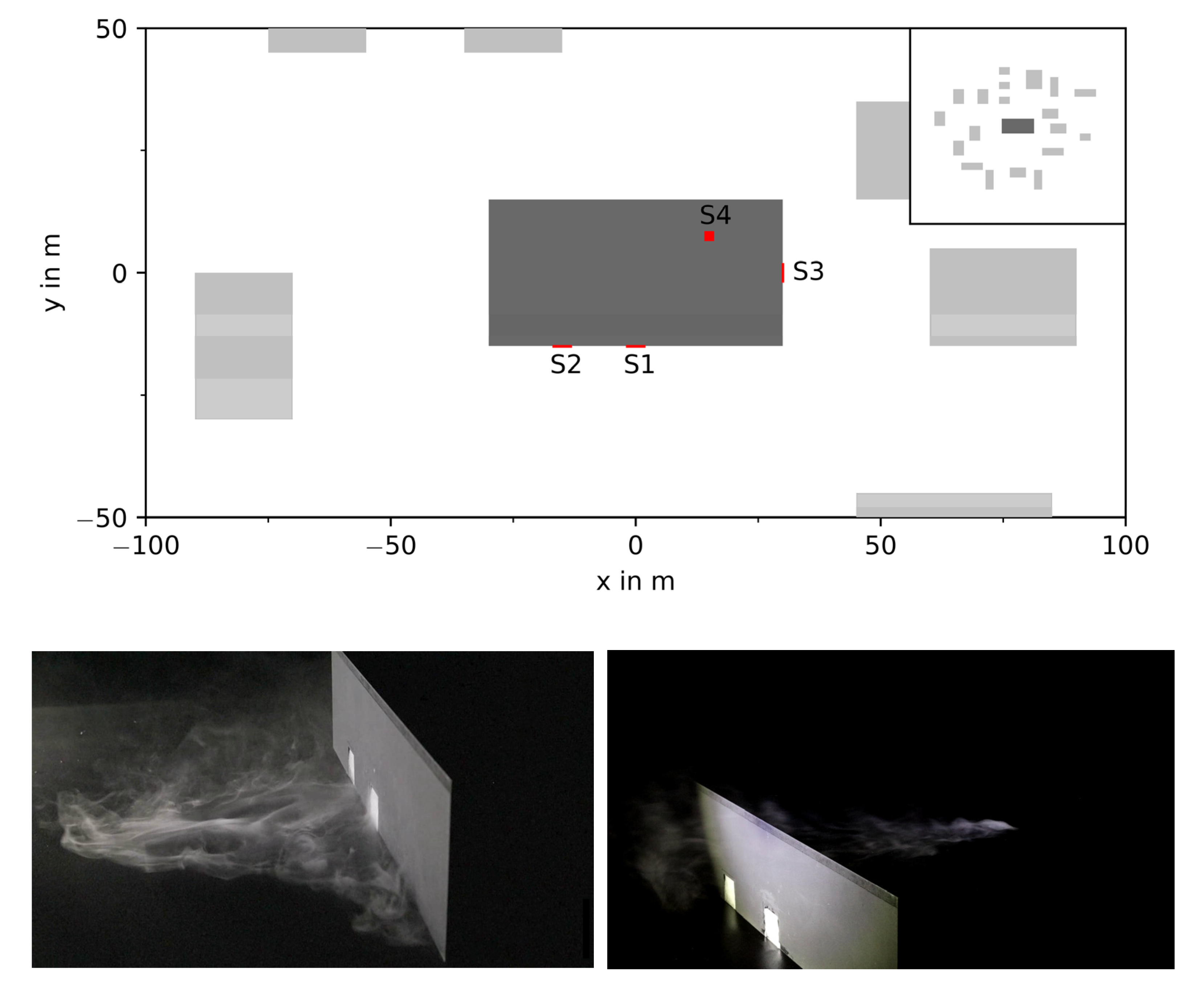
The model has a horizontal extent of approx. 300 m by 300 m and consists of 20 cuboid shaped buildings. All buildings have a height of 15 m. The horizontal extents of the buildings range from 15 m to 60 m. Spacings between the buildings are between 10 m to 80 m. A large storage building (30 m × 60 m) is located in the middle of the model area.
In these experiments, the source location was varied according to
Figure 3. All sources are located at the storage building, which has three openings on the sides with a size of 4 m × 4 m (two on a long side: S1, S2 and one on a short side S3) and one opening with a size of 2 m × 2 m on the roof of the building (S4). During each experiment, only one source location was used, and the other three openings were closed, respectively.
The experiments for neutrally buoyant continuous gas releases have been performed with ethane with combinations of source location, boundary layer approach flow and wind direction according to
Table 2. The mass flows were set to achieve a low momentum release. The mass flows are not reported in
Table 2 as the experiments achieved source strength independency of the gas dispersion measurements by replacing the measured concentrations with:
Herein, the dimensionless concentration c*, depending on a reference velocity uref, a characteristic length scale Lref (here Lref = 1/100 m) and the volumetric source flow allow for the CFD simulations to be carried out for different reference velocities and volumetric source flows.
For the heavy gas dispersion experiments, a mixture of CO
2 and butane with a density of 1.84 kg/m
3 at the source was released. The different setups investigated are given by
Table 3. For heavy gas dispersion, the approach of the dimensionless concentration
c* is not applicable, as the heavy gas effects do not allow for source strength independency; the respective mass flows are given in the table.
The “Points” Column in
Table 2 and
Table 3 indicates the total number of sample points per experiment. The samples are not distributed in a regular pattern but their location is optimized to detect the gas cloud contour.
5. Results
Based on the presented wind tunnel experiments, an assessment of the accuracy of the presented model has been carried out. In [
10], a first assessment of the wind field prediction based on the method of the VDI Guideline 3783/9 has been carried out, mainly for the generic cases described in the guideline. The assessment presented here covers all presented wind tunnel trials to evaluate the gas dispersion in a built-up environment.
5.1. Evaluation of the Wind Field
As described in chapter 3, wind tunnel experiments have been carried out for three different configurations of a built-up environment. In a first step, the wind profiles are used to investigate the accuracy of the model prediction of the atmospheric boundary layer flow. For each of the three cases M1, M2 and M3, the medium ground roughness (MR) and the high ground roughness (HR) were investigated for different mesh resolutions.
Table 4 shows the hit rate of the simulations for each of the investigated configurations. In each column, the hit rate for the horizontal velocity component in main wind direction
qu and cross to the main wind direction
qv are given. A hit rate for the vertical velocity component could not be calculated, as the experimental value was not measured.
The average value of the hit rate clearly indicates that higher values are achieved for the horizontal cross wind component than for the horizontal main wind direction component. A detailed consideration of each case shows that the threshold value of 66% is often only closely missed for the cases M1 and M2 for the horizontal main wind direction component. Whilst the VDI Guideline 3783/9 states that a successful validation is reached when the hit rate is higher than 66%, this value will be considered here only as a reference and not as a threshold. In the VDI Guideline 3783/9, all points for which the hit rate is to be determined are located at heights up to 75 m height over ground, where ground effects do not play a role, while the wind tunnel values used here are mainly located near-ground at heights up to 4 m over ground. It could be observed that for points of the wind tunnel measurements located in heights of more than 4 m, the hit rate threshold of 66% could be achieved, whilst this was not the case for points at lower heights.
As expected, grid refinement leads to higher hit rates. Nevertheless, if the computational time is considered, it should be stated that an evenly spaced grid with a cell size of 0.5 m (∆ = 0.5 m, ∆w = 0.5 m), or an evenly spaced grid with 0.5 m cells and a local cell size of 0.25 m at buildings (∆ = 0.5 m, ∆w = 0.25 m), severely increases the computational time without significant improvements on the hit rate. Taking the evenly spaced 1 m grid as a reference, with average computational time of around 830 CPUh (CPUh = number of real time hours multiplied by the number of CPU used = number of hours required when using a single CPU), the computational time increases by more than a factor of 5 for the ∆ = 0.5 m, ∆w = 0.5 m grid and by a factor of nearly 10 for the ∆ = 0.5 m, ∆w = 0.25 m grid, whilst the hit rate in y direction remains nearly unchanged and the hit rate in x direction is not increased by more than 10%. In the following, for the built-up area investigations, only the ∆ = 1 m, ∆w = 1 m mesh and the ∆ = 2 m, ∆w = 0.5 m mesh will be considered, as they show similar computational times with slightly better hit rates for the mesh with local refinement.
In [
10], the generic cases of the VDI Guideline 3783/9 were investigated and it was already observed that lower hit rates were achieved when the flow approaches the buildings with a non-perpendicular angle (oblique inflow), which corresponds to the observations for case M3.
Figure 4 shows, for the oblique inflow case (M3), the calculated vectors of the horizontal velocity components in red arrows and the measured ones in black. While on the left side of
Figure 4 the boundary conditions were setup to match exactly the documented conditions in the wind tunnel (incident flow at an angle of 30° to the buildings centerline), the representation on the right side shows the wind field for a simulation with an incident flow of 35°. The slight modification of the angle of the incident flow has considerable effect on the resulting wind field, especially in the vicinity of the buildings, showing a clearly better agreement between the model results and experiment.
This observation shows that the model is very sensitive to any deviation in the geometry. This results from the fact that if flow separations at building edges are insufficiently captured by the turbulence model, this can lead to significantly different flow patterns. One insufficiently captured flow separation at a single upstream edge can lead to a totally different flow pattern downstream due to error propagation. Therefore, special attention must be paid to the degree of detail used in the model, e.g., a deviation of 1 mm in the wind tunnel would result in a deviation of 0.1 m in reality with the scaling factor of 100 from model scale to real scale in the presented experiments. In practical applications of CFD simulations, the level of detail of the geometry representation (e.g., balconies, roof shapes, trees, etc.) is to be investigated carefully.
The sensitivity of the simulation result towards slightly varying angles of the incident flow or geometry details clearly show that for hazard analysis purposes, CFD simulations should not be carried out for a single angle of the wind direction but for the desired angle ± a certain offset that has to be defined specifically, depending on the investigated problem, to ensure that possible deviations between reality and the geometrical model are taken into account when calculating the hazardous area.
All the investigations are focused on the wind speed and direction. As no explicit data of the turbulent kinetic energy were measured, the accuracy of the turbulence prediction is deduced in the following from the gas dispersion simulation. As it has been shown that the prediction of the velocity field is achieved in a satisfactory manner, it is safe to assume that if the prediction of the gas concentrations is valid, the turbulence is implicitly valid since it has a direct influence on the gas dispersion.
5.2. Evaluation of the Neutrally Buoyant Gas Dispersion
The evaluation of the turbulence prediction using the presented model is conducted for a neutrally buoyant gas dispersion in a flat terrain without obstacles. The absence of obstacles is purposeful in order to avoid influences of the buildings on the turbulence, so that only the prediction of the incident atmospheric boundary layer flow turbulence is investigated here.
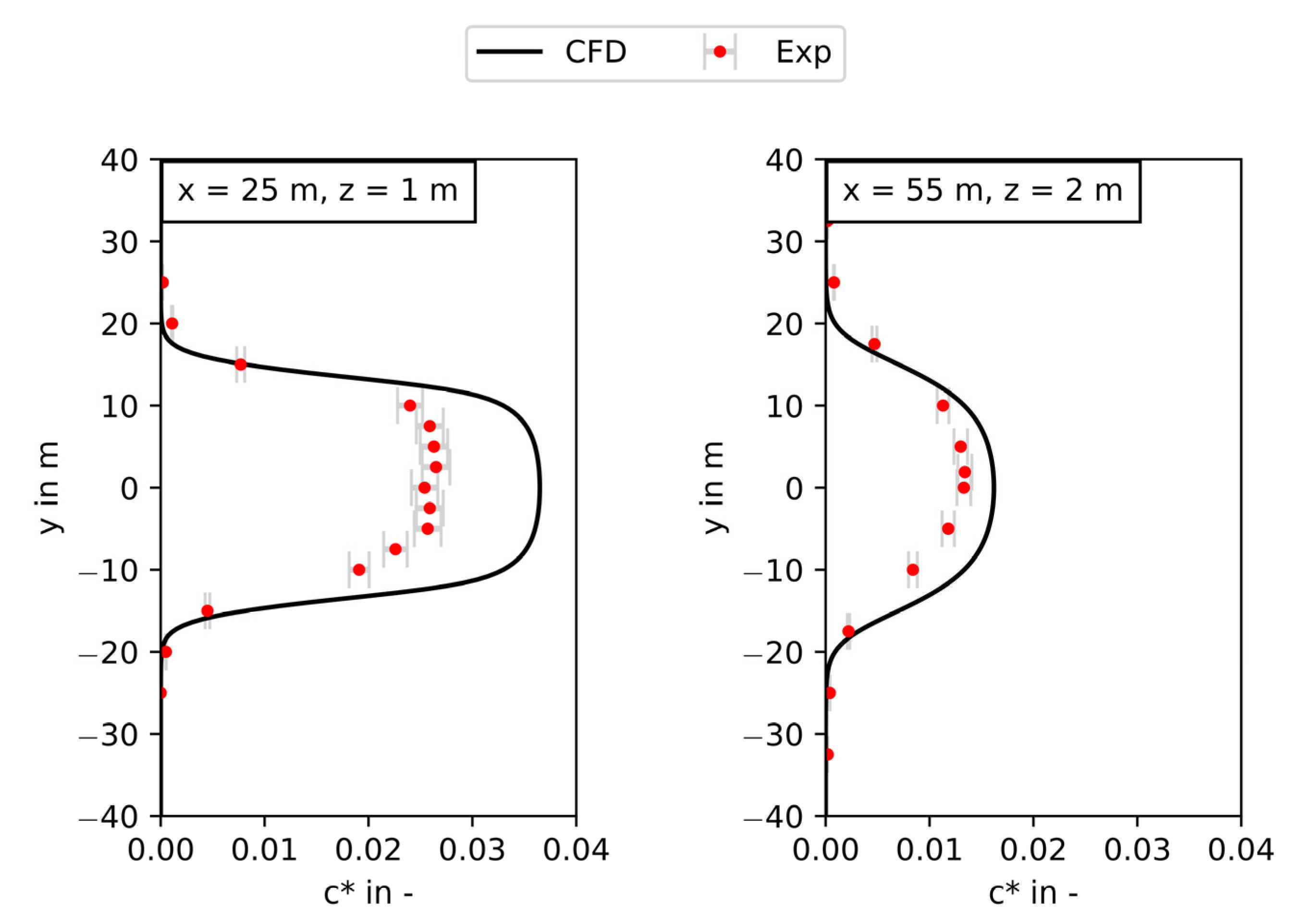
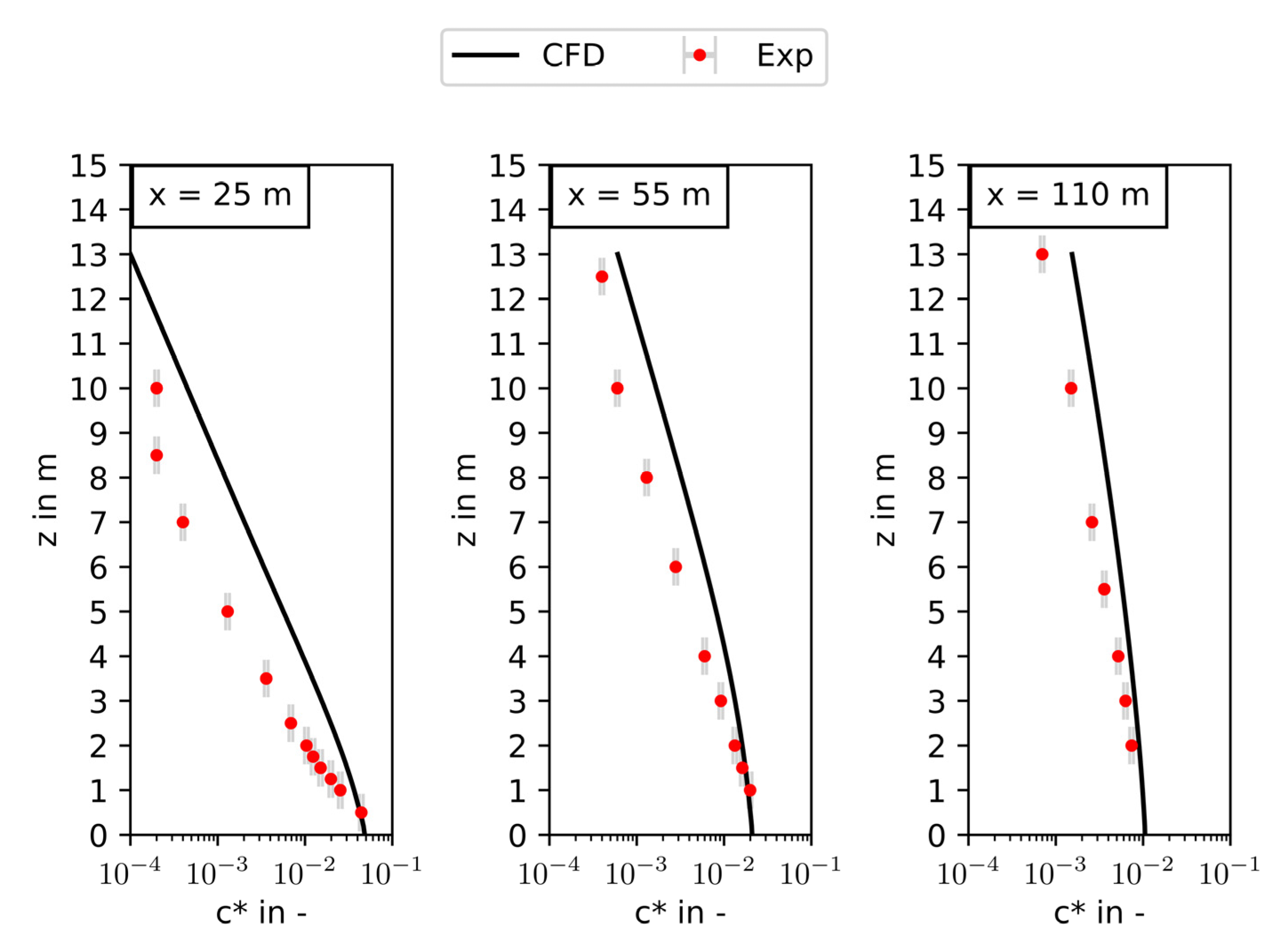
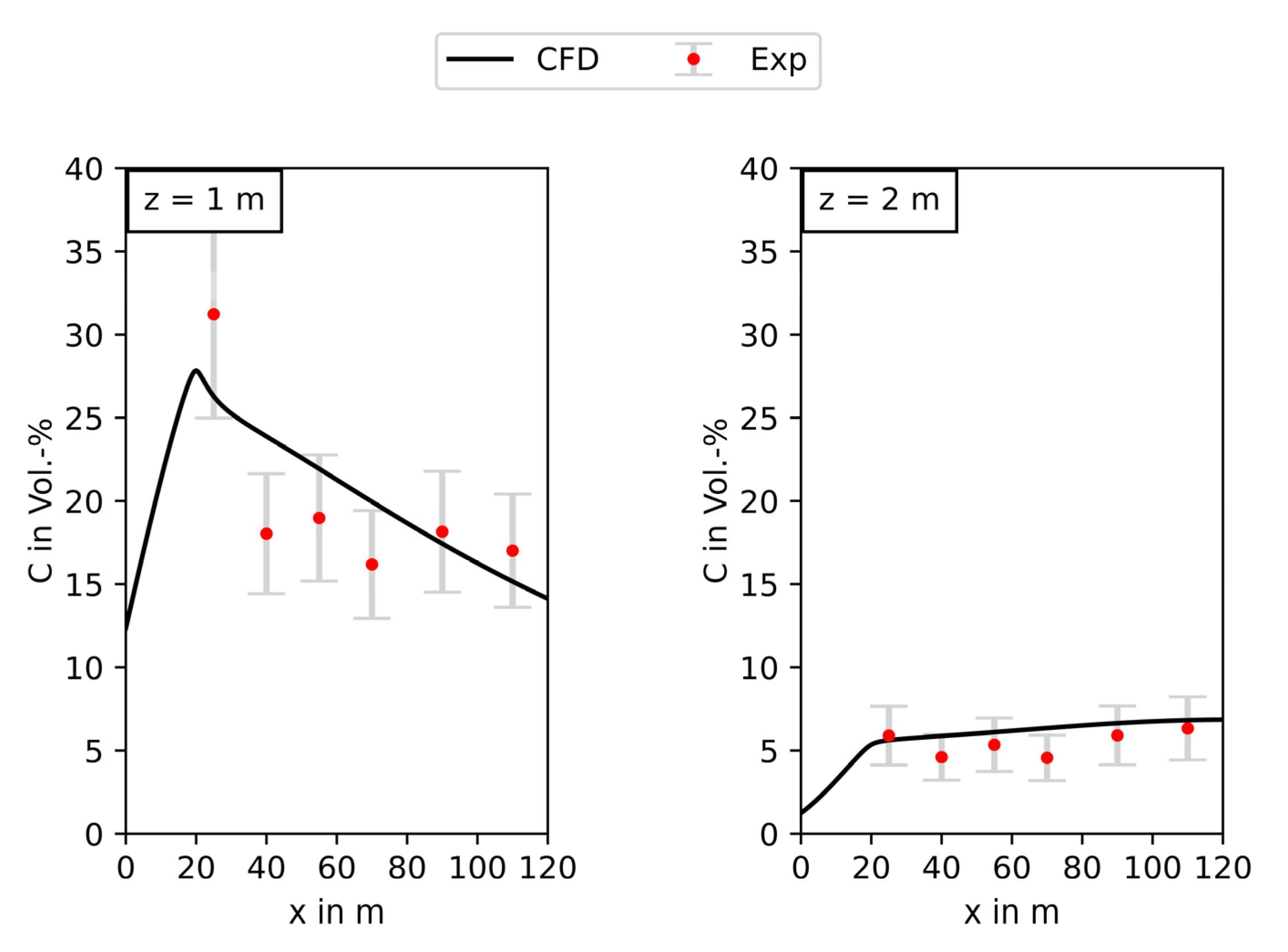
Figure 5 shows the dimensionless cloud centerline concentration
c* over the distance from a 40 meter-long and 25 meter-wide source for medium ground roughness (MR), on the left in a height of 1 m over ground and on the right in a height of 2 m over ground. The origin of the
x-axis is in the middle of the source; therefore, concentrations between 0 m and 20 m distance are located over the source.
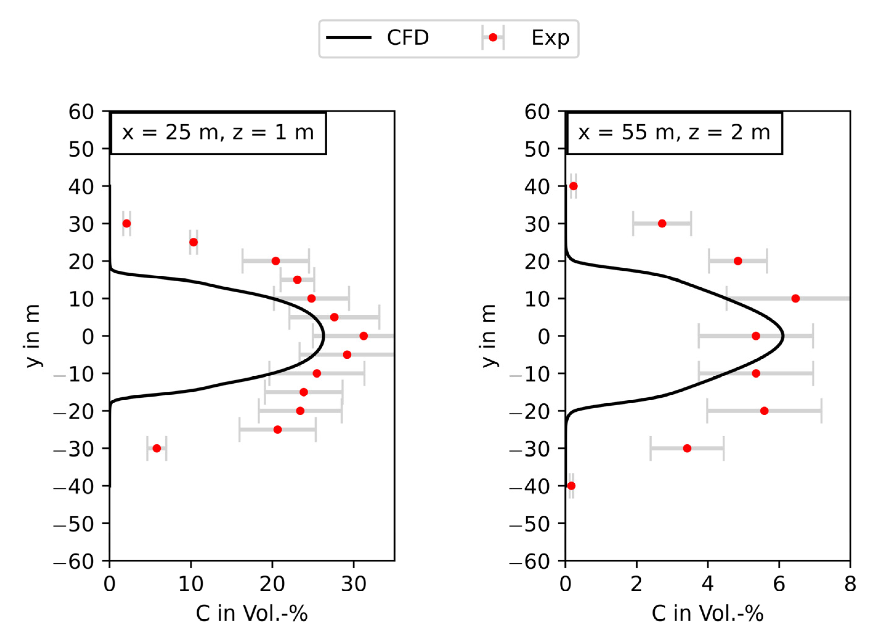
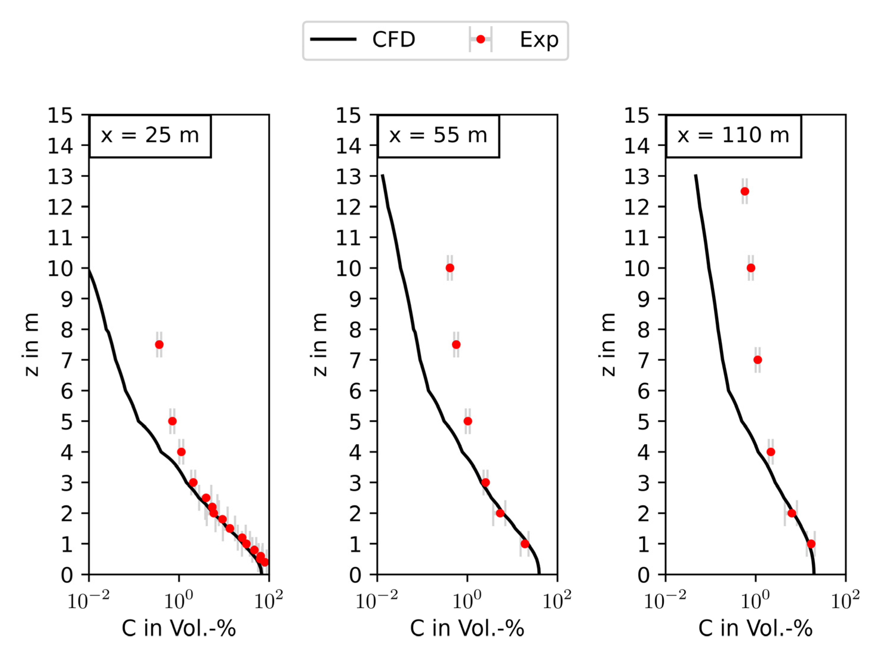
Figure 5 shows that, although the concentrations over the source were overpredicted, the gas dispersion is predicted with a good accuracy within a distance of “one source length” (in this case from around x = 60 m). Therefore, it is safe to assume that the atmospheric turbulence in the undisturbed flow (downstream of the source) is predicted adequately. The overestimation of the concentrations over the source might be due to an underestimation of the turbulence resulting from the release. This can also be confirmed for the width of the gas cloud (
Figure 6) and the vertical concentration profiles on the centerline of the gas cloud (
Figure 7) where the predicted concentrations are in good agreement with the measurements within “one source length” from the source.
After the successful validation of the wind field and turbulence prediction in a non-built-up environment, the gas dispersion of a neutrally buoyant gas has been investigated for a built-up environment (Cases M1–M3) and different ground roughness (MR and HR).
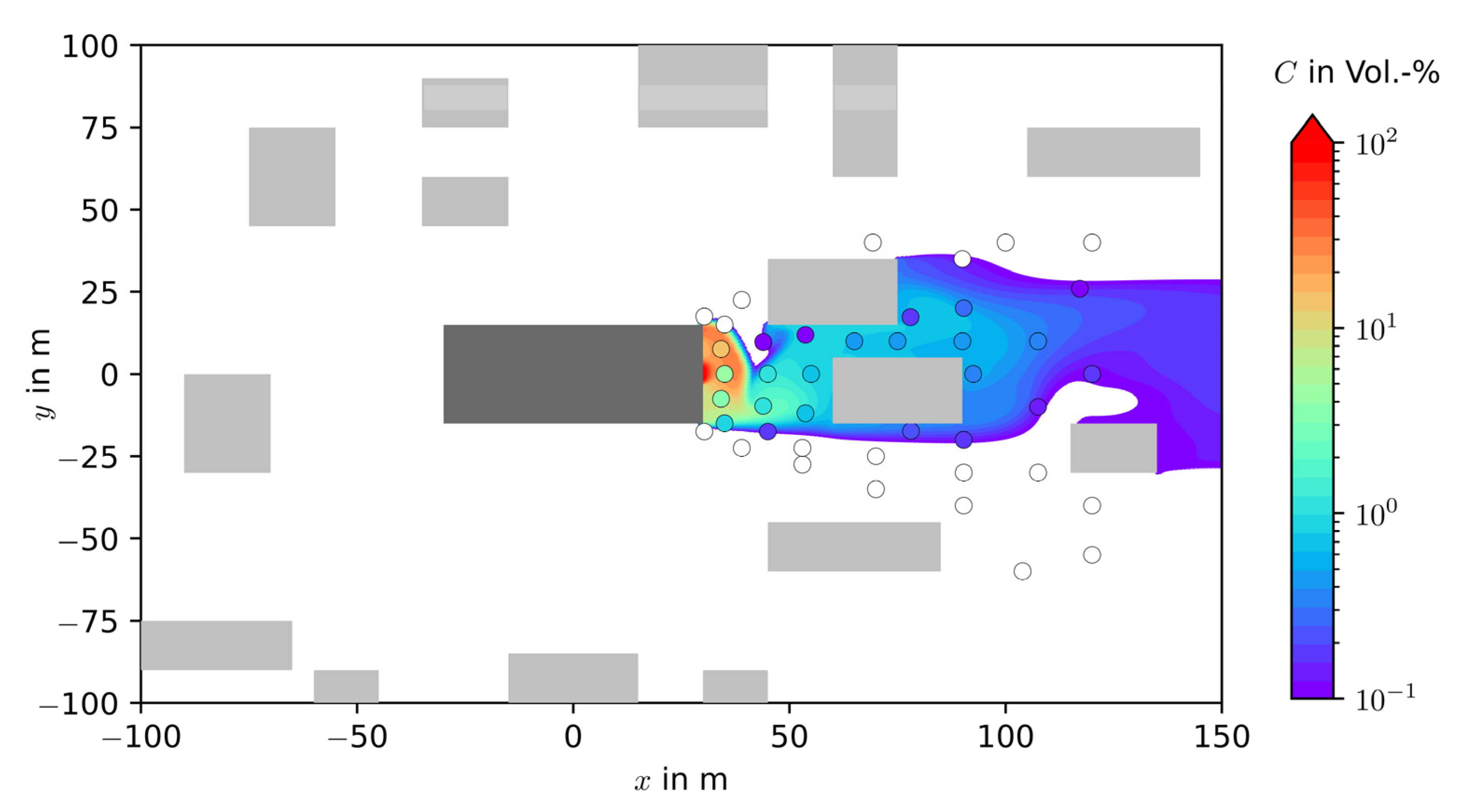
Figure 8 shows an example for case M1 with source S3, with a medium roughness; the predicted gas concentrations are presented as isosurface and the measured gas concentrations as bullet points. All values lower than 0.1 Vol.% are shown colorless/in white. The predicted gas cloud shows an excellent qualitative agreement with the measurements and a good quantitative agreement with a tendency towards overprediction.
While the quantitative performance indicator for the wind field, the hit rate, was only defined and designed for wind field assessment, the quantitative performance indicators, as given in [
24,
25,
26], are now used to evaluate the gas dispersion.
Table 5 shows the quantitative performance indicators for all investigated neutrally buoyant cases. According to the definition of [
24], the criteria for a good model performance are met for the mesh ∆ = 2 m, ∆
w = 0.5 m, as 50% of the cases reach the thresholds defined for at least 50% of the performance indicators. The ∆ = 1 m, ∆
w = 1 m mesh reaches the criterion for FAC2 in 80% of the cases but does not fulfill all requirements of [
24]. As already noticed for the wind field, the gas dispersion prediction in Case M3 is also not as accurate as for all the other cases.
The comparison of the hit rate in
Table 4 with the performance indicators in
Table 5 shows that, while the refinement of the mesh has little to no effect on the quality of the wind field prediction, the refinement of the mesh is clearly noticeable for the gas dispersion. In addition, it can be seen that for the same wind field (case MR-M1), the gas dispersion shows different levels of agreement with the measurements, depending on the source location (S1–S4). It can be concluded that the validation of CFD-models should always focus on the main interesting variable (in this case, the resulting concentration distribution of the gas dispersion), and not only on the validation of influencing variables (such as the wind field).
5.3. Evaluation of the Heavy Gas Dispersion
As for the validation of the turbulence of the wind field, which was carried out in a non-built-up environment in order to avoid obstacle-induced effects, the validation of the damping of the turbulent species transport due to heavy gas effects is also performed for a flat terrain. The concentration profile over the distance to the source is shown in
Figure 9. The predicted concentrations of the heavy gas cloud are in good agreement with the measured values.
The cloud width (
Figure 10) is slightly underpredicted, while the maximum extent of the gas cloud in wind direction is estimated with good accuracy.
Figure 11 shows the vertical concentration profiles with a good prediction of the gas concentrations near-ground and a tendency to underpredict the concentrations in greater distances from the ground.
From these observations, it can be concluded that the damping of the turbulence due to heavy gas effects implemented in the model presented here is working in a satisfactory manner.
Representative for all other cases of heavy gas dispersion in a built-up environment, Case MR-M1-S3 is discussed here.
Figure 12 (left side) shows the gas dispersion in a height of 2 m over the ground as isosurface. The measuring points of the wind tunnel experiments are represented by bullets. As for the neutrally bouyant gas, a very good qualitative agreement between measurements and predictions can be obeserved and the quantitative estimation of the concentration still shows a good agreement. Values below 0.1 Vol.% are not represented in the diagram.
The vertical distribution of the concentration is shown in
Figure 12 (right side) on a cut plane directly on the centerline of the source (y = 0 m in
Figure 12, left side) in a range of the
x-axis of 20 m–80 m. The “zigzag-behavior” at the top of the isocontour is not a physical effect but a rendering error of the visualization tool used. The white spots on
Figure 12 (right side) between the two buildings are areas with concentrations below 0.1 Vol.%. The heavy gas behavior of the gas cloud is very well represented and in good agreement with the measurements.
Table 6 summarises the quantitative performance indicators for all investigated heavy gas dispersion cases. The criterion of reaching the threshold values for at least 50% of the performance indicators in at least 50% of the case is met. For the ∆ = 1 m, ∆
w = 1 m mesh, eight out of nine cases meet the criteria, and for the ∆ = 2 m, ∆
w = 0.5 m mesh, nine out of nine cases. According to the defintion of the Cost Action 1006, the model performance can be defined as very good.
It is of note that (especially when comparing
Table 5 and
Table 6) the FB values are generally negative, which corresponds to an overestimation of the concentration by the simulation. This effect is probably due to an underestimation of the obstacle-induced turbulence using the presented model, since a majority of the reference points of the measurements lay in the vicinity of the obstacles and the turbulence evaluation for flat terrain showed a very good performance.
After the successful validation of the model, the calculation of hazardous areas for two specific cases is looked at more closely. Whilst simpler models (e.g., VDI Guideline 3783/2) only provide a radius of the hazardous area around the source, resulting in a circle, this model can predict irregular shapes and the hazardous area for sources that are not flush with the ground. As an example,
Figure 13 shows the influence of the buildings on the shape and extent of the hazardous area for a vertical source (S1). The “canalization” effect downstream of the source leads to a clearly different estimate of the hazardous area compared to the circle around the source given by, e.g., the VDI Guideline 37837/2. Results such as the one shown in
Figure 13 also lead to the question of whether simpler approaches are still to be considered as conservative, since it is not possible to take into account the canalization of the gas cloud in “channels”. As an example, the distance calculated by the VDI Guideline 3783/2 to reach 1 Vol.% is 126 m for the mean dispersion situation. This value is clearly lower than the distance reached by the isocontour of 1 vol.% in
Figure 13; therefore, an underprediction of the maximum distance occurs here.
Another interesting effect is shown on
Figure 14. The source (S4) is located on the roof of the central building. The gas dispersion is shown at a height of 16 m over ground (left side) and at a height of 2 m over ground (right side). While significant concentrations occur in greater heights (left side), the gas density, as well as the influence of the recirculation zone downstream of the building, leads to a movement of the cloud in the direction of the ground and, consequently, to reduced concentrations at the ground. The model predictions in this case are, again, in good agreement with the experimental observations in the wind tunnel. These types of elevated sources can not be taken into account using simpler models such as the VDI Guideline 3783/2. As the latter assumes a ground source, the distance of 88 m (mean dispersion situation) predicted by the Guideline until the concentration of 1 Vol.% is reached is now clearly overestimating the concentrations at the ground predicted by the experiments and the presented model.
6. Conclusions
Modelling the near-ground heavy gas dispersion in a built-up environment under atmospheric conditions for hazard assessment purposes is a challenge. In addition to a prediction of the heavy gas effects, such as the negative buoyancy and the turbulence damping due to density gradients, it is mandatory to model the atmospheric near-ground boundary layer flow. Simple approaches such as the VDI Guideline 3783/2, based on wind tunnel experiments, fulfill all these conditions but are subject to limitations when it comes to a correct representation of the reality. Besides restricted geometrical options for the dispersion areas, the source is always located near-ground. Existing approaches for adapting CFD models to simulate the heavy gas dispersion under atmospheric conditions are dependent on the ground roughness length , and therefore limited in the grid resolution near-ground.
In this work, a model based on the OpenFOAM CFD Code adapted to solve the near-ground heavy gas dispersion under atmospheric conditions was presented. The wind field model is independent of the roughness length , enabling a high near-ground resolution required for the gas dispersion simulation. The wind field modelling was validated in an earlier publication against wind tunnel measurements of the VDI Guideline 3783/9 and, here, against new wind tunnel measurements. In both cases, the evaluation of the model accuracy using the hit rate as defined in the VDI Guideline 3783/9 showed a good agreement, even for the built-up scenarios investigated here.
To investigate the accuracy of the turbulence prediction in the atmospheric flow in built-up areas, wind tunnel experiments with neutrally buoyant gas releases were carried out. The model, evaluated using quantitative performance indicators, showed a good performance in predicting the gas concentrations, implicitly validating the turbulence prediction.
The presented heavy gas model with the newly developed damping of the turbulent species transport was validated against the wind tunnel experiments for heavy gas dispersion in built-up areas. Using the same quantitative performance indicators as for the neutrally buoyant cases, the model showed a very good performance.
Applying the evaluation criteria of the quantitative performance indicators to all cases (neutrally buoyant and heavy gas release) investigated, the presented model reaches the thresholds for more than 50% of the performance indicators for more than 50% of the total of the cases, which makes it suitable for all investigated applications.
For hazard assessment purposes in built-up areas, it is recommended to simulate the gas dispersion not only for the desired inflow angle, but also for ±an offset, since the velocity field is very sensitive to slight deviations in the geometrical configuration and, as in reality, the wind direction will not be constant over the release duration. With such an angle offset, it can be ensured that the prediction for the (combined) hazardous area will be conservative.
The presented model not only showed a good prediction performance but also enables the consideration of complex release scenarios (e.g., varying building/obstacle configurations, source location on the roof of a building or out of a window) and under varying atmospheric flow conditions with a reasonable cost/benefit ratio.


