
Numerical Investigation on Mixing Characteristics and Mechanism of Natural Gas/Air in a Super-Large-Bore Dual-Fuel Marine Engine


Abstract
1. Introduction
2. Model Description and Validation
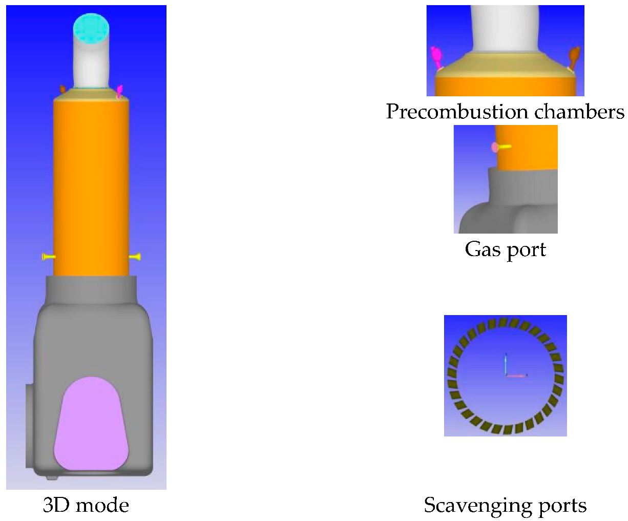
2.1. Investigated Engine
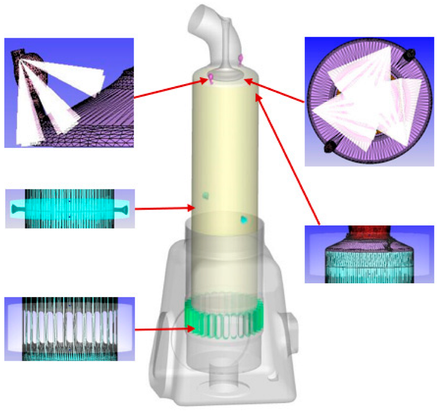
2.2. CFD Model Description
2.3. CFD Simulation Model Calibration
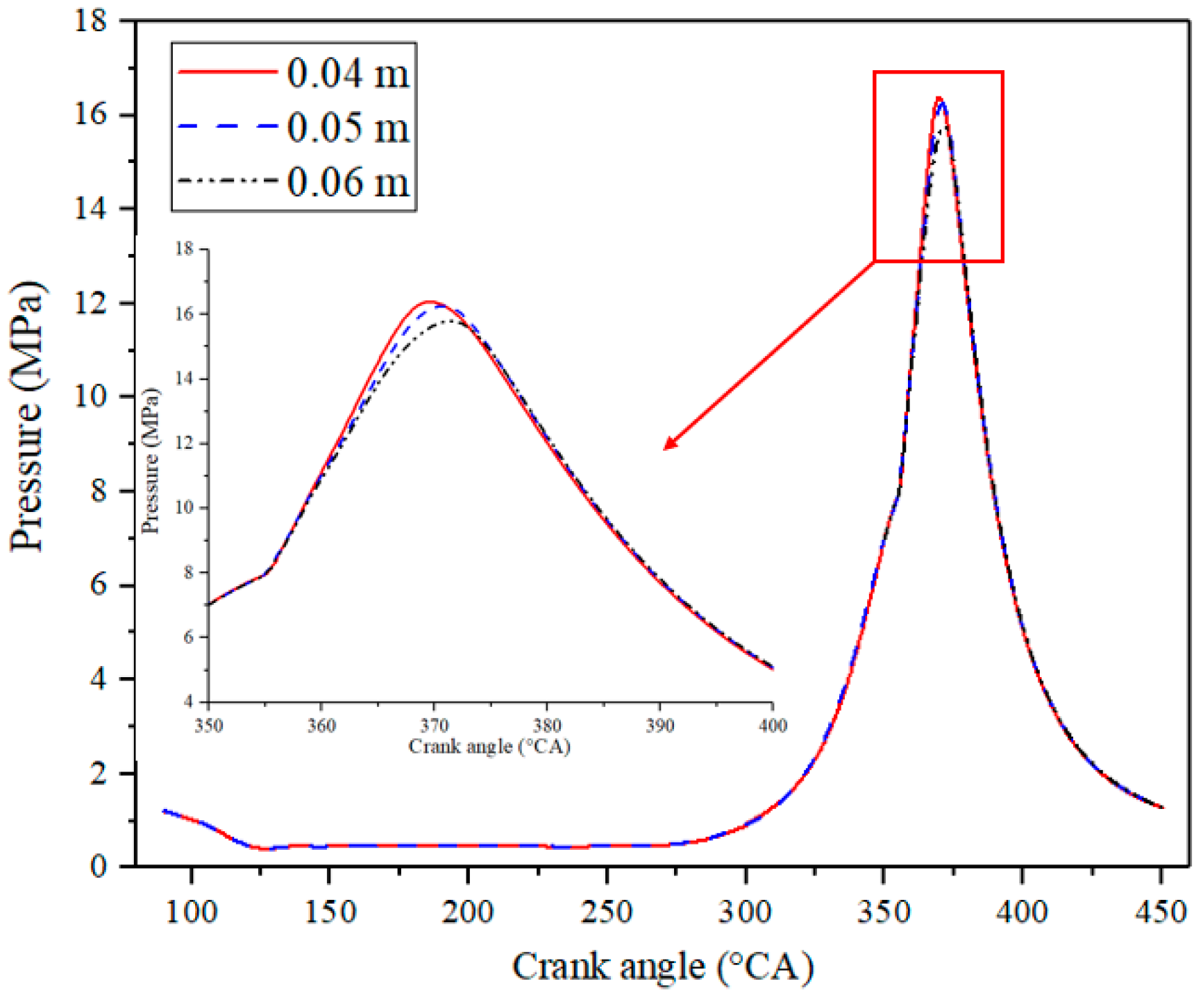
2.3.1. Grid Independence
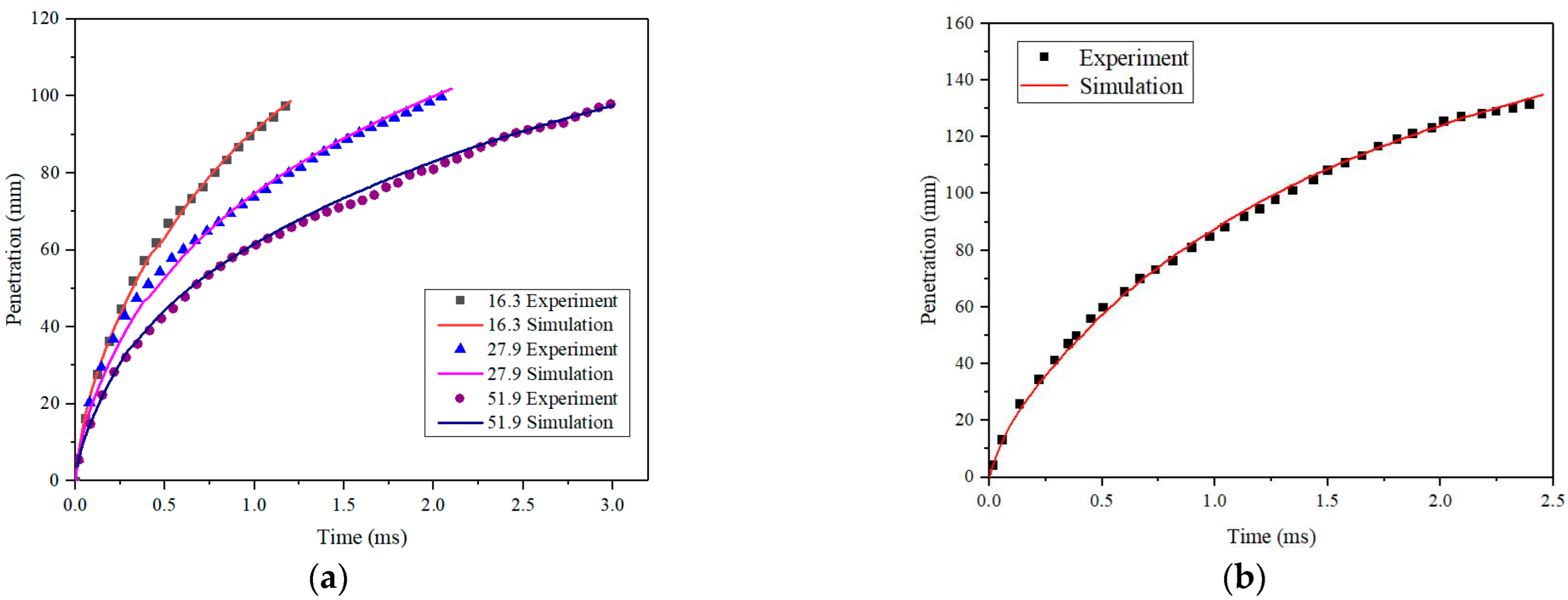
2.3.2. Diesel Spray Validation
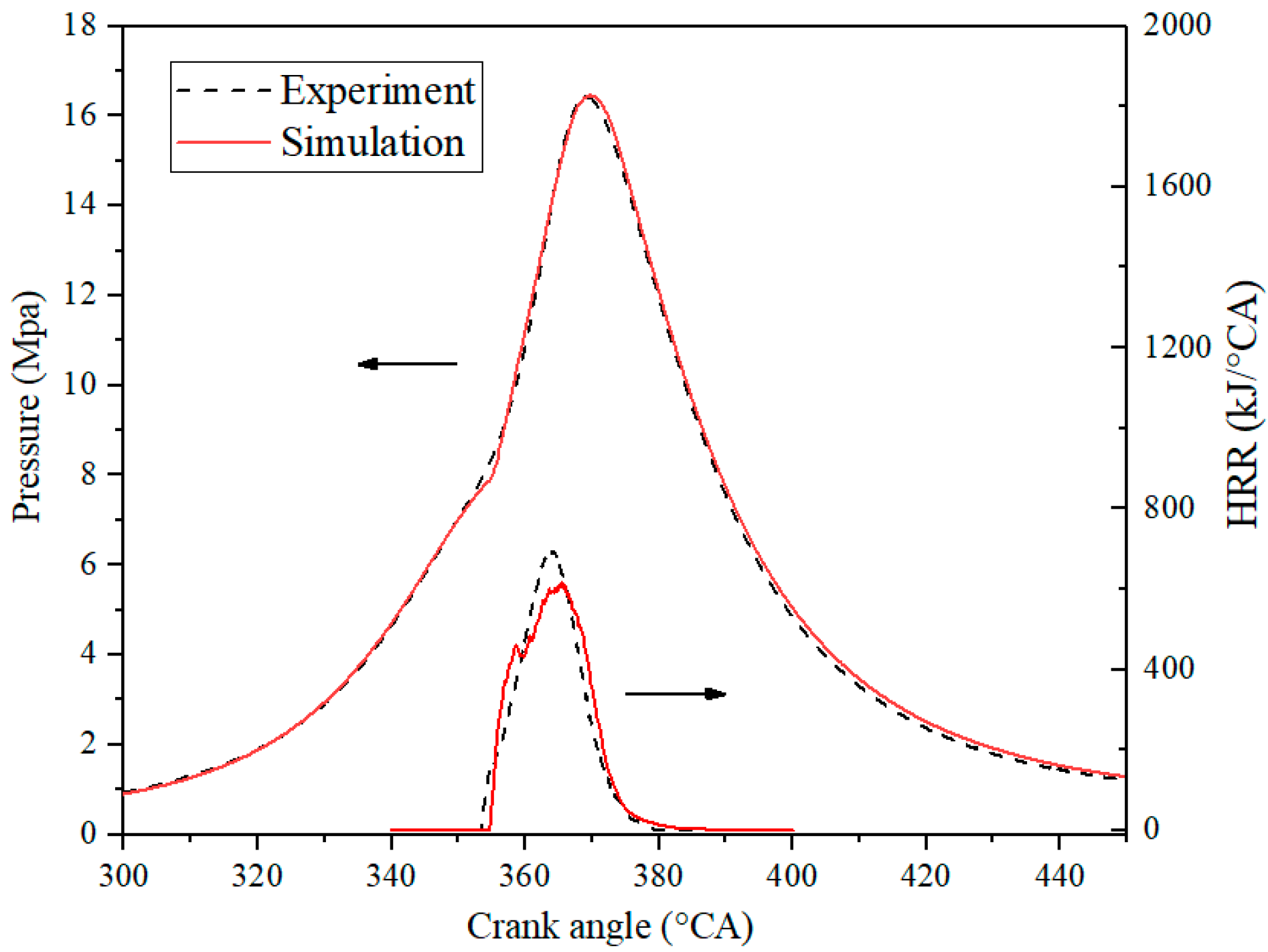
2.3.3. Chemical Kinetic Mechanism Validation
3. Results and Discussion
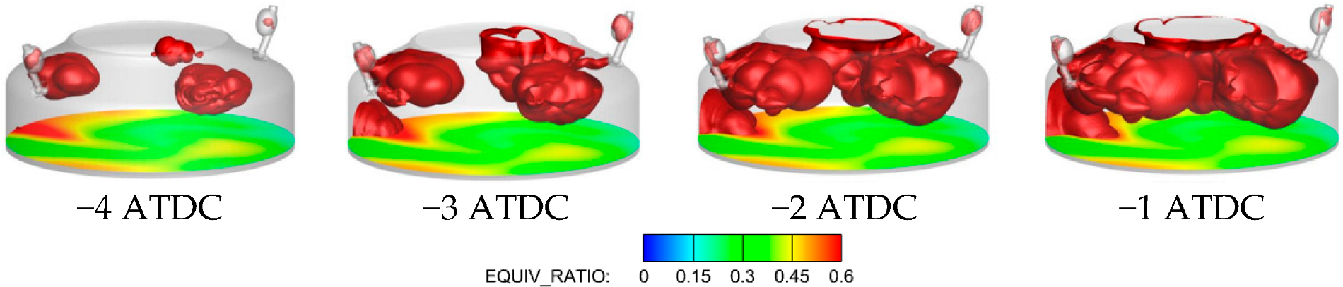
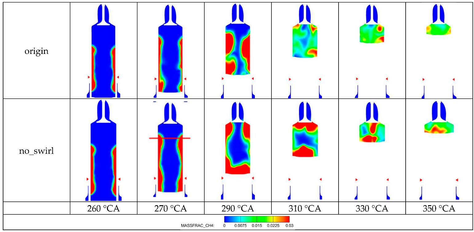
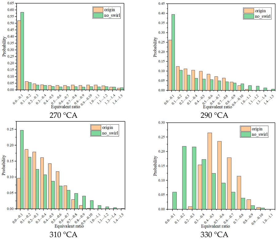
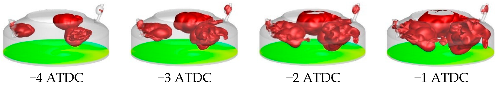
3.1. Effect of NG Distribution on Combustion
3.2. Mixing Mechanism of NG and Air
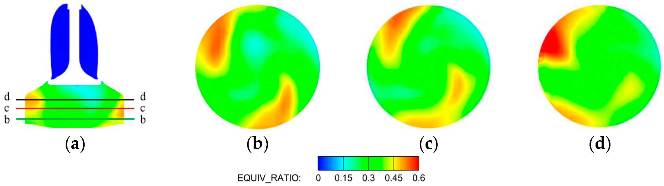
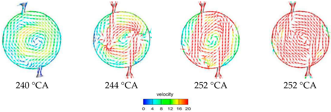
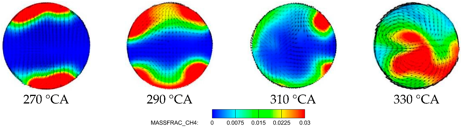
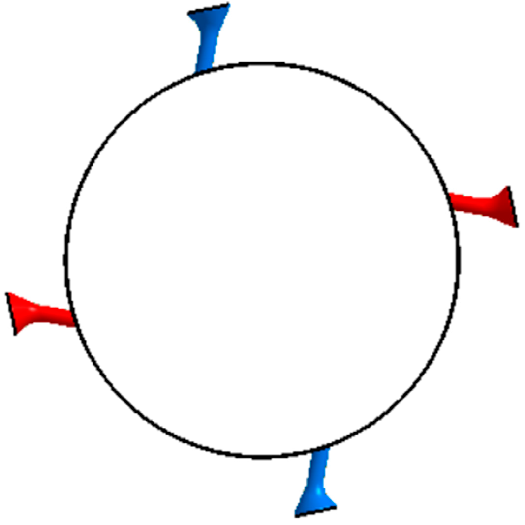
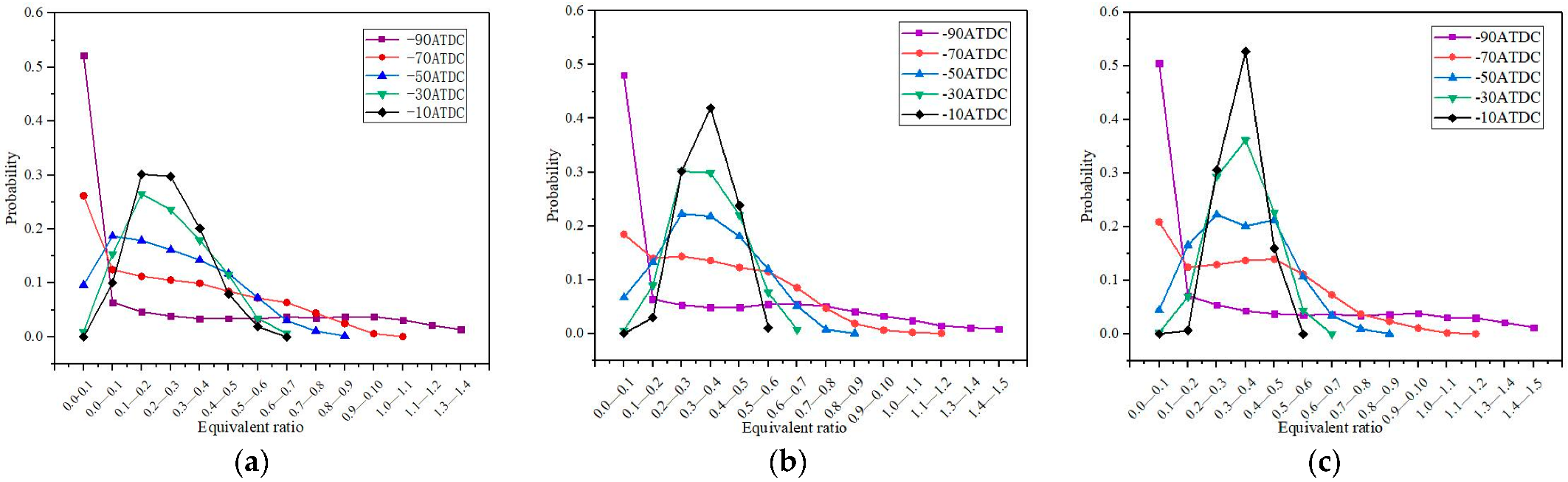
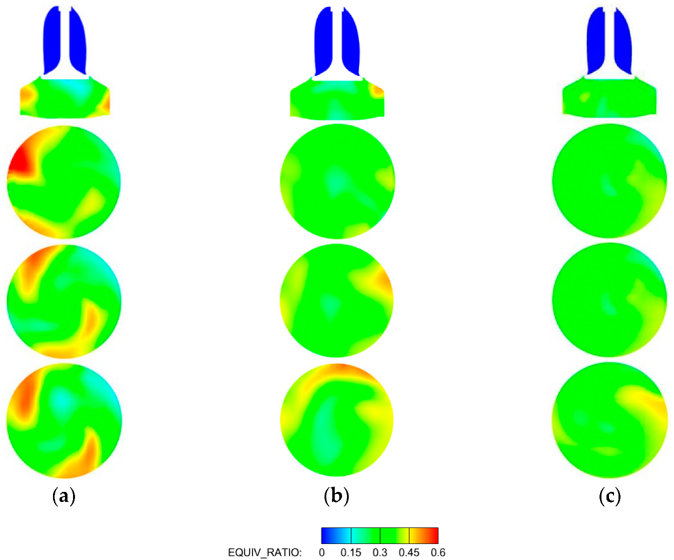
3.2.1. Influence of Flow on the Distribution of NG
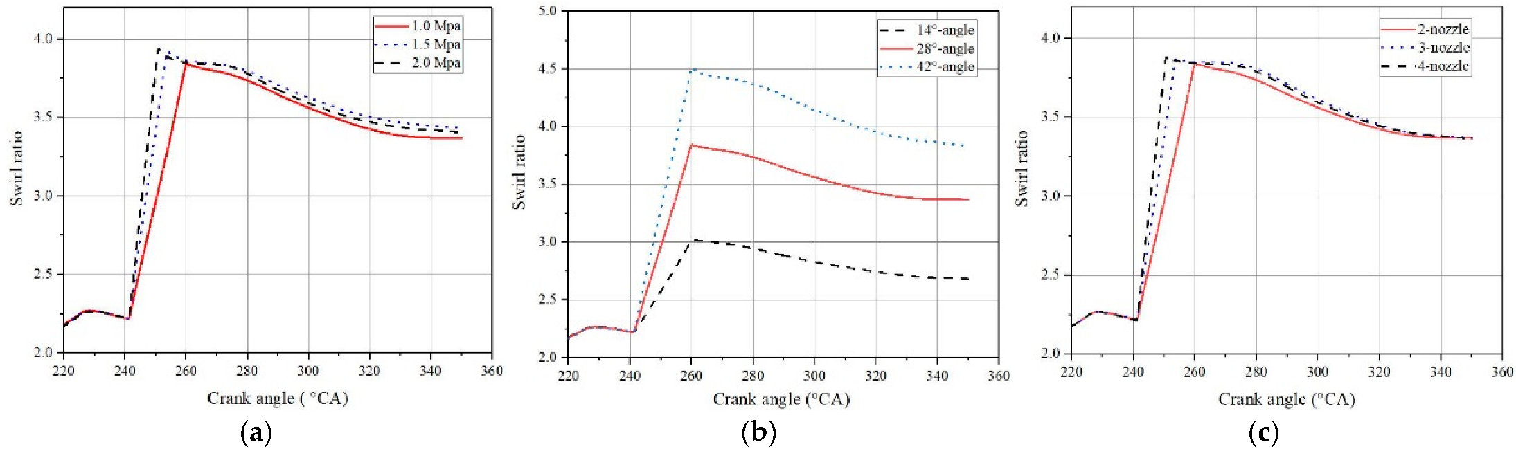
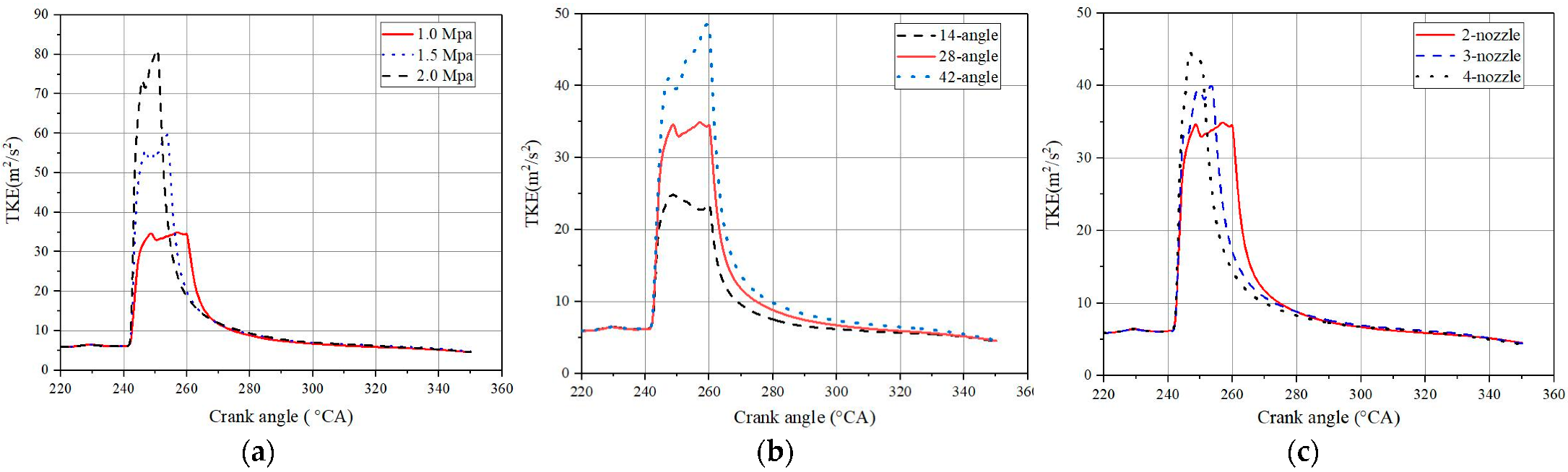
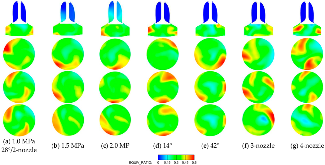
3.2.2. Effects of NG Injection Condition on NG Distribution
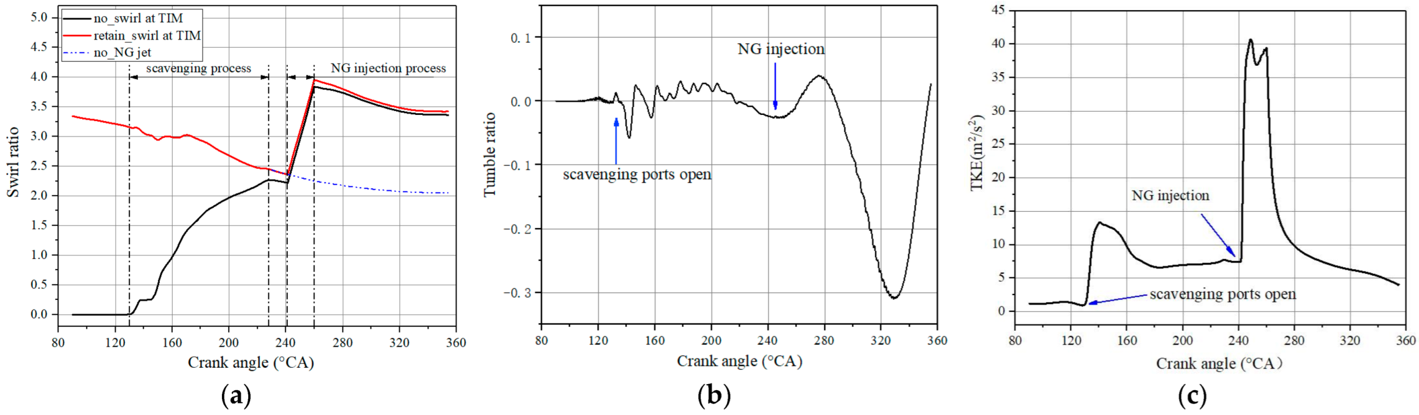
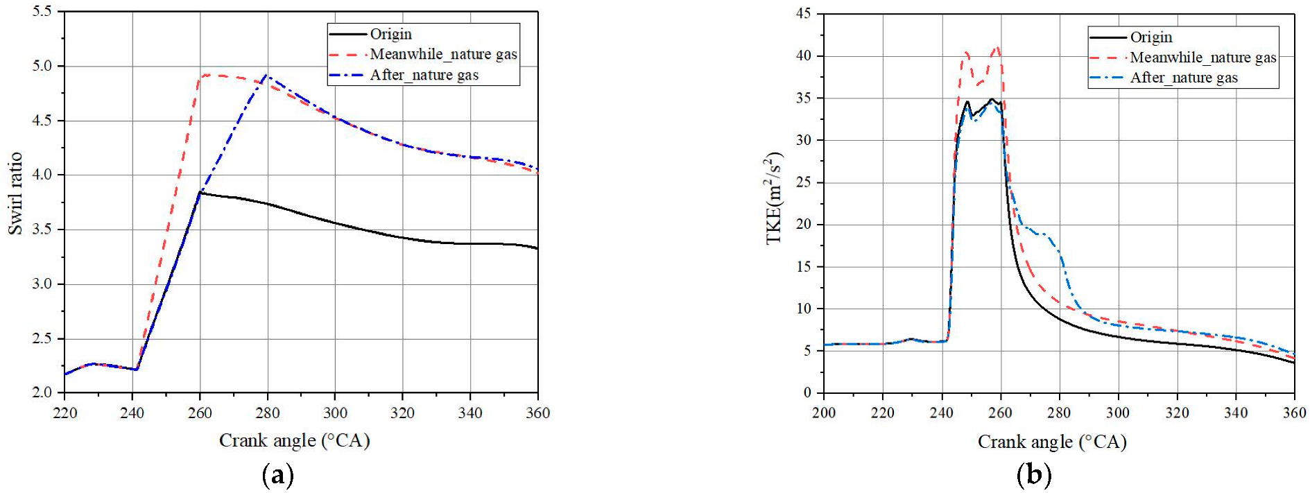
3.3. Methods to Improve the Intensity of Swirl in Cylinder
4. Conclusions
- (1)
- The calculated results reveal the disadvantage of even mixture formation due to the characteristics of low flow-field disturbance and rapid dissipation of TKE of large-bore marine engines, which leads to the phenomenon of abnormal combustion occurring at the area of accumulation of NG in the cylinder.
- (2)
- The numerical simulation results show that the level of swirl has a greater influence on the flow field in-cylinder and NG transportation compared to the tumble during the scavenging and compression process. In addition, the NG injection process plays a more important role in the swirl and turbulence in the cylinder compared to the scavenging process.
- (3)
- Furthermore, the simulation results reveal that the main factors affecting the transmission process of NG and distribution of CH4 concentration are the intensity of in-cylinder turbulence and the level of swirl at the late compression stage. However, the enhanced swirl intensity by changing the condition of NG has little effect on the transmission process of NG and distribution of CH4 concentration.
- (4)
- With a certain amount of air injected into the cylinder, the area of high concentration of mixtures before TDC decreases significantly. It illustrates that the strategy can effectively improve the premixed charge mixing and avoids the occurrence of abnormal combustion in the cylinder. Moreover, this solution can be implemented by applying the original air compression system of marine engines, which will expand the application of NG in marine engines.
Author Contributions
Funding
Conflicts of Interest
Abbreviations
| 3-D | Three-Dimensional |
| ATDC | After Top Dead Centre |
| CFD | Computational Fluid Dynamics |
| CH4 | Methane |
| DF | Dual-Fuel |
| DCC | Dynamic Combustion Control |
| EVC | Exhaust Valve Closing |
| HFO | Heavy Fuel Oil |
| IMO | International Maritime Organization |
| MDO | Marine Diesel Oil |
| NG | Natural Gas |
| NOx | Nitrogen Oxides |
| Probability Density Function | |
| SR | Swirl Ratio |
| TDC | Top Dead Center |
| TR | Tumble Ratio |
| TKE | Turbulence Kinetic Energy |
| Win GD | Winterthur Gas and Diesel |
References
- Larsen, U.; Wronski, J.; Andreasen, J.G.; Baldi, F.; Pierobon, L. Expansion of organic Rankine cycle working fluid in a cylinder of a low-speed two-stroke ship engine. Energy 2017, 119, 1212–1220. [Google Scholar] [CrossRef]
- Zhu, Y.; Zhou, W.; Xia, C.; Hou, Q. Application and Development of Selective Catalytic Reduction Technology for Marine Low-Speed Diesel Engine: Trade-Off among High Sulfur Fuel, High Thermal Efficiency, and Low Pollution Emission. Atmosphere 2022, 13, 731. [Google Scholar] [CrossRef]
- Yoo, B.-Y. Economic assessment of liquefied natural gas (LNG) as a marine fuel for CO2 carriers compared to marine gas oil (MGO). Energy 2017, 121, 772–780. [Google Scholar] [CrossRef]
- International Maritime Organization (IMO). Greenhouse Gas Emissions; International Maritime Organization: London, UK, 2018. [Google Scholar]
- Degiuli, N.; Martić, I.; Farkas, A.; Gospić, I. The impact of slow steaming on reducing CO2 emissions in the Mediterranean Sea. Energy Reports 2021, 7, 8131–8141. [Google Scholar] [CrossRef]
- Ampah, J.D.; Yusuf, A.A.; Afrane, S.; Jin, C.; Liu, H. Reviewing two decades of cleaner alternative marine fuels: Towards IMO’s decarbonization of the maritime transport sector. J. Clean. Prod. 2021, 320, 128871. [Google Scholar] [CrossRef]
- Elkafas, A.G.; Elgohary, M.M.; Shouman, M.R. Numerical analysis of economic and environmental benefits of marine fuel conversion from diesel oil to natural gas for container ships. Environ. Sci. Pollut. Res. Int. 2021, 28, 15210–15222. [Google Scholar] [CrossRef]
- Iannaccone, T.; Landucci, G.; Tugnoli, A.; Salzano, E.; Cozzani, V. Sustainability of cruise ship fuel systems: Comparison among LNG and diesel technologies. J. Clean. Prod. 2020, 260, 121069. [Google Scholar] [CrossRef]
- Wei, L.; Geng, P. A review on natural gas/diesel dual fuel combustion, emissions and performance. Fuel Process. Technol. 2016, 142, 264–278. [Google Scholar] [CrossRef]
- Richardson, D.E. Review of Power Cylinder Friction for Diesel Engines. J. Eng. Gas Turbines Power 2000, 122, 506–519. [Google Scholar] [CrossRef]
- Chen, Y.; Raine, R. A study on the influence of burning rate on engine knock from empirical data and simulation. Combust. Flame 2015, 162, 2108–2118. [Google Scholar] [CrossRef]
- Feng, D.; Buresheid, K.; Zhao, H.; Wei, H.; Chen, C. Investigation of lubricant induced pre-ignition and knocking combustion in an optical spark ignition engine. Proc. Combust. Inst. 2019, 37, 4901–4910. [Google Scholar] [CrossRef]
- Chen, L.; Zhang, R.; Wei, H.; Pan, J. Effect of flame speed on knocking characteristics for SI engine under critical knocking conditions. Fuel 2020, 282. [Google Scholar] [CrossRef]
- Liu, L.; Wu, Y.; Wang, Y. Numerical investigation on knock characteristics and mechanism of large-bore natural gas dual-fuel marine engine. Fuel 2022, 310, 118846. [Google Scholar] [CrossRef]
- Gürbüz, H.; Akçay, İ.H.; Buran, D. An investigation on effect of in-cylinder swirl flow on performance, combustion and cyclic variations in hydrogen fuelled spark ignition engine. J. Energy Inst. 2014, 87, 1–10. [Google Scholar] [CrossRef]
- Cao, Z.; Wang, T.; Sun, K.; Cui, L.; Gui, Y. Numerical Analysis of Scavenging Process in a Large Marine Two-Stroke Diesel Engine; SAE Technical Paper Series; Society of Automotive Engineers (SAE): Warrendale, PA, USA, 2017. [Google Scholar]
- Yousefi, A.; Guo, H.; Birouk, M. Effect of swirl ratio on NG/diesel dual-fuel combustion at low to high engine load conditions. Appl. Energy 2018, 229, 375–388. [Google Scholar] [CrossRef]
- Wang, G.; Yu, W.; Li, X.; Su, Y.; Yang, R.; Wu, W. Experimental and numerical study on the influence of intake swirl on fuel spray and in-cylinder combustion characteristics on large bore diesel engine. Fuel 2019, 237, 209–221. [Google Scholar] [CrossRef]
- Choi, M.; Park, S. Effects of intake air conditions and micro-pilot (MP) injection timing on micro-pilot dual fuel (MPDF) combustion characteristics in a single cylinder optical engine. Energy Convers. Manag. 2022, 254, 115281. [Google Scholar] [CrossRef]
- Liu, Z.; Zhou, L.; Liu, B.; Zhao, W.; Wei, H. Effects of equivalence ratio and pilot fuel mass on ignition/extinction and pressure oscillation in a methane/diesel engine with pre-chamber. Appl. Therm. Eng. 2019, 158, 113777. [Google Scholar] [CrossRef]
- Yousefi, A.; Guo, H.; Birouk, M. Split diesel injection effect on knocking of natural gas/diesel dual-fuel engine at high load conditions. Appl. Energy 2020, 279, 115828. [Google Scholar] [CrossRef]
- Yang, B.; Ning, L.; Liu, B.; Huang, G.; Cui, Y.; Zeng, K. Comparison study the particulate matter characteristics in a diesel/natural gas dual-fuel engine under different natural gas-air mixing operation conditions. Fuel 2021, 288, 119721. [Google Scholar] [CrossRef]
- Abdelaal, M.M.; Rabee, B.A.; Hegab, A.H. Effect of adding oxygen to the intake air on a dual-fuel engine performance, emissions, and knock tendency. Energy 2013, 61, 612–620. [Google Scholar] [CrossRef]
- Liu, L.; Wu, Y.; Xiong, Q.; Liu, T. Analysis on flow motion and combustion process in pre-chamber and main chamber for low-speed two-stroke dual. SAE Technol. Pap. 2019. [Google Scholar] [CrossRef]
- Li, M.; Zhang, Q.; Li, G.; Li, P. Effects of hydrogen addition on the performance of a pilotignition direct-injection natural gas engine: A numerical study. Energy Fuel 2017, 31, 4407–4423. [Google Scholar] [CrossRef]
- Mavrelos, C.; Theotokatos, G. Numerical investigation of a premixed combustion large marine two-stroke dual fuel engine for optimising engine settings via parametric runs. Energy Convers. Manag. 2018, 160, 48–59. [Google Scholar] [CrossRef]
- Jiang, X.; Wei, H.; Zhou, L.; Chen, R. Numerical Study on the Effects of Multiple Injection Coupled with EGR on Combustion and NOx Emissions in a Marine Diesel Engine. Energy Procedia 2019, 158, 4429–4434. [Google Scholar] [CrossRef]
- Patterson, M.A.; Reitz, R.D. Modeling the effects of fuel spray characteristics on diesel engine combustion and emission. SAE Trans. 1998, 107, 27–43. [Google Scholar]
- Rahimi, A.; Fatehifar, E.; Saray, R.K. Development of an optimized chemical kinetic mechanism for homogeneous charge compression ignition combustion of a fuel blend of n-heptane and natural gas using a genetic algorithm. Proc. Inst. Mech. Eng. Part D J. Automob. Eng. 2010, 224, 1141–1159. [Google Scholar] [CrossRef]
- Özgül, E.; Şimşek, M.; Bedir, H. Use of thermodynamical models with predictive combustion and emission capability in virtual calibration of heavy duty engines. Fuel 2020, 264, 116744. [Google Scholar] [CrossRef]
- Naber, J.; Siebers, D. Effects of gas density and vaporization on penetration and dispersion of diesel sprays. SAE Technol. Pap. 1996, 105, 82–111. [Google Scholar]
- Von Rotz, B.; Herrmann, K.; Boulouchos, K. Experimental Investigation on the Characteristics of Sprays Representative for Large 2-Stroke Marine Diesel Engine Combustion System. SAE Technol. Pap. 2015. [Google Scholar] [CrossRef]
- Abidin, Z.; Florea, R.; Callahan, T. Dual Fuel Combustion Study Using 3D CFD Tool. SAE Technol. Pap. 2016. [Google Scholar] [CrossRef]
- Liu, H.; Li, J.; Wang, J.; Wu, C.; Liu, B.; Dong, J.; Liu, T.; Ye, Y.; Wang, H.; Yao, M. Effects of injection strategies on low-speed marine engines using the dual fuel of high-pressure direct-injection natural gas and diesel. Energy Sci. Eng. 2019, 7, 1994–2010. [Google Scholar] [CrossRef]
- Wang, H.; Gan, H.; Theotokatos, G. Parametric investigation of pre-injection on the combustion, knocking and emissions behaviour of a large marine four-stroke dual-fuel engine. Fuel 2020, 281, 118744. [Google Scholar] [CrossRef]


| Parameters | Value |
|---|---|
| Cylinder number | 12 |
| Bore/stroke [mm] | 920/3468 |
| Engine speed [rpm] | 80 |
| Compression ratio | 12.4 |
| Engine output [KW] | 63,840 |
| IMEP (MCR) | 17.3 |
| Parameters | Value |
|---|---|
| Engine load [%] | 100% |
| Initial cylinder pressure [bar] | 12.1 |
| Initial temperature in cylinder [K] | 930 |
| Scavenge inlet pressure [bar] | 4.7 |
| Scavenge inlet temperature [K] | 301 |
| Outlet pressure of exhaust [bar] | 4.55 |
| Outlet pressure of exhaust temperature [K] | 737 |
| Cylinder wall temperature [K] | 443 |
| The SOI of the main diesel fuel [°CA/ATDC] | −6 |
| The SOI of the pilot diesel fuel [°CA/ATDC] | −5 |
| Parameters | Model |
|---|---|
| Turbulence | RNG κ-ε k-ε model |
| Gas injection | Inflow boundary |
| Spray atomization and breakup | KH-RT |
| Droplet collision | NTC collision method |
| Spray–wall interaction | O’Rourke model |
| Combustion | Chemical kinetic model |
| NOx | Extended Zeldovich model |
| Grid Strategy | Region | Size [mm] |
|---|---|---|
| Basic grid | Overall model | 40 |
| Scavenging port | 5 | |
| Natural gas injection | 5 | |
| Fixed embedding | Combustion region | 2.5 |
| Precombustion chambers | 2.5 | |
| Diesel injection | 2.5 | |
| AMR | Overall model | 2.5 |
| Parameters | Value |
|---|---|
| Nozzle diameter [mm] | 40 |
| Injection duration [°CA] | 18 |
| Injection angle [°] | 28 |
| Injection pressure [MPa] | 1.4 |
| Injection timing [°CA] | During and after gas injection (242/260) |
Publisher’s Note: MDPI stays neutral with regard to jurisdictional claims in published maps and institutional affiliations. |
© 2022 by the authors. Licensee MDPI, Basel, Switzerland. This article is an open access article distributed under the terms and conditions of the Creative Commons Attribution (CC BY) license (https://creativecommons.org/licenses/by/4.0/).
Share and Cite
Liu, L.; Liu, S.; Xia, Q.; Liu, B.; Ma, X. Numerical Investigation on Mixing Characteristics and Mechanism of Natural Gas/Air in a Super-Large-Bore Dual-Fuel Marine Engine. Atmosphere 2022, 13, 1528. https://doi.org/10.3390/atmos13091528
Liu L, Liu S, Xia Q, Liu B, Ma X. Numerical Investigation on Mixing Characteristics and Mechanism of Natural Gas/Air in a Super-Large-Bore Dual-Fuel Marine Engine. Atmosphere. 2022; 13(9):1528. https://doi.org/10.3390/atmos13091528
Chicago/Turabian StyleLiu, Long, Shihai Liu, Qian Xia, Bo Liu, and Xiuzhen Ma. 2022. "Numerical Investigation on Mixing Characteristics and Mechanism of Natural Gas/Air in a Super-Large-Bore Dual-Fuel Marine Engine" Atmosphere 13, no. 9: 1528. https://doi.org/10.3390/atmos13091528
APA StyleLiu, L., Liu, S., Xia, Q., Liu, B., & Ma, X. (2022). Numerical Investigation on Mixing Characteristics and Mechanism of Natural Gas/Air in a Super-Large-Bore Dual-Fuel Marine Engine. Atmosphere, 13(9), 1528. https://doi.org/10.3390/atmos13091528