Abstract
This study was conducted to examine the effect on airflow of the shape of an urban road green belt in an asymmetrical street canyon. In this paper, the airflow field at pedestrian height in an asymmetrical street with different building height ratios (ASF) on both sides of the street is modeled and simulated using computational fluid dynamics (CFD) software, ANSYS FLUENT, and the flow rate characteristic distribution index and the average airflow intensity index are used to evaluate and analyze the airflow at the pedestrian level. The study shows that: (1) in an empty street scheme with different building ratios, the static wind area is located on the roof of the downstream building; the closer to the ground in a street with an ASF = 1/3, the lower the airflow rate. However, the situation is the opposite of that in other streets (2/3, 3/1, and 3/2). (2) The position of the green belt makes the windward side flow rate in the step-up street higher than that of the leeward side, and the flow rate of the leeward side in the step-down street is higher than that of the windward side. (3) Compared with other green belt forms, the use of two plates and three belts in the incremental street can increase the circumferential sinking at the roofs of the windward side of the street, thereby improving the wind environment in the entire street. The use of one plate, two-belt and three-plate, four-belt scenarios in the step-down street allows the two ends of the corner vortex to carry more airflow into the interior of the street and reduces both the “wind shadow effect” area in the middle of the street and the “air outlet effect” at both ends.
1. Introduction
In 1950, only 30% of the world’s population lived in cities and towns; in 2018, the figure had already reached 55% and will rise to 66% by 2050. The environment in which most people live is the urban covering layer from the ground to the building, which is part of the rough sub-layer of the atmospheric boundary layer; its flow statistical characteristics strongly depend on the actual shape and layout of obstacles such as buildings [1,2]. In May 2021, 15 departments, including the Chinese Ministry of Housing and Urban–Rural Development, issued the document: “Opinions on Strengthening Green and Low-Carbon Construction in County Towns,” which stated that the heights of residential buildings in county towns should be strictly limited, and the proportion of residential buildings with six floors and below should not be less than 70% [3]. That is, the buildings in these areas should mainly be low-rise buildings and multi-story buildings. Taller buildings will cause wind effects and phenomena such as angular flow, vortexes, and even a changing wake under various wind field conditions, inconveniencing pedestrians while walking, causing poor ventilation in local areas, and forming local microclimate phenomena in urban regions with street canyons [4,5].
Many cities use vegetation such as green belts to provide shade, purify the air, alleviate local air pollution, and actively improve the local microclimate in street canyons. However, recent studies have produced conflicting results and comments that it is not feasible to use vegetation to slow down and purify the air. The aerodynamic effects of vegetation such as green belts are much stronger than their pollutant removal capabilities [6]. In the open road space, vegetation has a positive impact on reducing particulate matter [7]; the specific situation varies according to the complex pollution reduction principle of plants [8,9,10]. The internal flow field of the road space in an urban street canyon is more complex [11] and is closely related to the geometric characteristics of the street canyon, such as the symmetry of the street, the shape of the street canyon, the aspect ratio of the buildings, etc. [12,13]. Relevant studies have shown that the shape and the symmetry of the street canyon have a higher degree of influence on the internal flow field and pollutant diffusion than other street canyon characteristics and factors [14].
The shape of street canyons can be divided into shallow street valleys (H/W ≤ 0.5), ideal street valleys (H/W ≈ 1), and deep street valleys, according to the ratio of the building height (H) on both sides of the street valley to the street valley width (W). When the ratio is H/W ≥ 2, compared with other wind directions, the internal flow field of a typical street valley under the conditions of vertical wind direction is more complex. There are three flow forms comprising sliding flow [15], and the influence of vegetation such as green belts in the shallow street valleys near the ground, which cause local airflow changes, is generally greater than that in ideal street valleys and deep street valleys [16]. The symmetry of the street canyon can be divided into symmetrical and asymmetric streets, according to the ratio (ASF) of the building height on the windward side (H1) to the building height on the leeward side (H2). At present, the research object is mainly projected for a scenario based on relatively symmetrical street canyons, but the buildings to both sides of the actual street canyons are generally asymmetrical structures, with one side higher and the other lower [17].
Street canyons are the basic units that make up a city, and the shape of road green belts in street canyons is the core content of road green space planning and design [18]. Therefore, based on comparing the two geometric types of asymmetric streets (step-up/step-down), this paper discusses the influence of road green belt shape on the airflow field and focuses on analyzing the airflow at pedestrian breathing height (1.5 m from the ground). The research results provide reference suggestions for improving the wind environment at pedestrians’ breathing height by rationally arranging the road green belt scenarios in different street canyon geometries, against the background of today’s increasingly extreme street canyon environment. The content of the research is designed to answer the following questions: (1) What are the effects of different building height ratios on each side and of different green belt scenarios on the spatial distribution of the airflow field in the street canyon? (2) Which type of green belt can most effectively improve the wind environment at pedestrian breathing height?
2. Methods
The main methods used to study the airflow field in street canyons are field measurements, the wind tunnel test, and numerical simulation. Field measurements are susceptible to errors that are caused by numerous factors, such as measurement methods and weather conditions. Wind tunnel tests can control the experimental conditions but their cost is high, and none of the types can obtain detailed airflow data. With the development of computer technology and numerical theory, computational fluid dynamics (CFD) numerical simulation has the advantages of a short experimental period and low cost and has become an essential means by which to study the law of airflow diffusion in street canyons.
There are many types of CFD numerical simulation software, such as PHOENICS, CFX, FLUENT, etc. The ANSYS FLUENT CFD is more suitable for fluid simulation than other software, with excellent results and fast calculation and convergence speed [19]. Therefore, this paper uses FLUENT CFD software to calculate the airflow in an empty street canyon with different building height ratios on both sides of the street, as well as a street canyon with different road green belt scenarios and using TECPLOT software for post-processing; it can then be used to extract the airflow velocity of different monitoring surfaces in the street canyon to map the inside of the empty street canyon. Finally, the spatial distribution trend of the airflow field and the impact of different green belt scenarios on the airflow at pedestrian breathing height in the street canyon are analyzed.
2.1. Study Area
The research area is Xilin Street, which is located in the Lin’an District, Hangzhou City, Zhejiang Province. Hangzhou city is located at latitude 30.250000 and longitude 120.166664. Lin’an District is 100 km wide from east to west and 50 km long from north to south, with a total area of 3118.77 km. The area has a subtropical monsoon climate, with an annual average temperature of 15.9 °C and an annual average wind speed of 1.3 m/s. The wind-rose map in Hangzhou is shown in Figure 1. The dominant wind direction in summer is southeasterly; typhoons and extreme cold fronts are occasionally encountered throughout the year, along with other catastrophic weather effects. Considering the research purpose and content of this paper, the street canyons measured in the research area meet the following requirements:

Figure 1.
Study Area.
- (1)
- The architectural layout form on both sides of the street and the spatial form of the road should have the standard characteristics of typical urban street valleys.
- (2)
- The greening conditions inside the street valley should be healthy and complete, and the sizes of the same types of trees and other vegetation should be as uniform as possible.
The final selected experimental site is Xilin Street (the third area of Country Garden); the street valley is connected to Tanxi Villa in the east and Zhejiang Agriculture and Forestry Affiliated Primary School in the north. The spatial forms of buildings and roads on both sides of the valley are continuous and relatively regular, which was convenient for field measurement and simulation verification in the subsequent analysis.
Field Measurements
In order to ensure that the statistical data showed certain typical characteristics, the period of survey and measurement was selected to be from 1 to 8 April 2022. In order to minimize the impact of human factors and traffic flow, the measurement period is a 1-h daytime period from 12 p.m. to 1 p.m. In order to reduce the influence of wider meteorological factors on the smooth flow in the street valley, the sampling experiment was carried out in sunny conditions with no wind or a light wind (wind < level 3) [20]. The measurement time of a single monitoring point was from 3 to 7 min. The actual measurement took 3 min, and the total time over which measurements are taken is about 1 h.
According to the conditions of the measured area and the measured geometric characteristic data from the street valley, ICEM-CFD is used to construct the measured model. The actual height measured at this time is the pedestrian breathing height at 1.5 m from the ground and at a height of 6 m. The monitoring surface of the street valley model and the location of the monitoring points are shown in Figure 2, yielding a total of two monitoring surfaces and 18 monitoring points. Figure 2 shows the measuring instrument and diagram of the monitoring points.
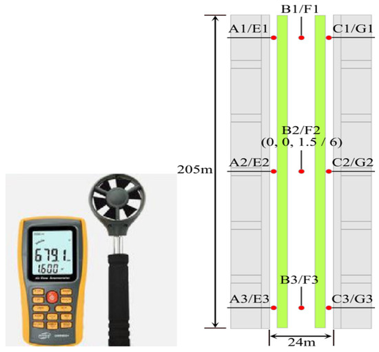
Figure 2.
Anemometer and monitoring points.
2.2. Numerical Model
A typical urban street canyon model is shown in Figure 3. The incoming wind direction is perpendicular to the buildings. If the heights of the buildings on both sides of the street are equal, the layout is known as a symmetrical street canyon; otherwise, it is known as an asymmetric street. Asymmetric streets are divided into two categories, according to the ratio of building heights on both sides (ASF); namely, LWB (windward-side building height): WWB (downwind-side building height). If the taller buildings are located on the leeward side (0 < ASF < 1), it is called a step-up canyon, and if the lower buildings are located on the leeward side (ASF > 1), it is called a step-down canyon [21].

Figure 3.
Typical urban street canyon model.
With reference to Gromke et al. [22], who reported wind tunnel tests conducted at Karlsruhe University in Germany, the best guidelines for the CFD simulation of atmospheric flow in urban environments are from the EU’s multinational long-term cooperation action plan for quality assurance and the improvement of microscale meteorological models (COST ACTION 732), along with the Implementation Guidelines for the CFD Simulation of Pedestrian-level Wind Around Buildings, proposed by the Architectural Institute of Japan [23,24,25]. These can be used to determine the computational domain and the shallow street canyon experimental model, where building height H = 18 m, street canyon width W = 36 m, and street canyon length L = 180 m; on this basis, according to the different ratios of building heights (ASF) on both sides of the street canyon, the quantitative design of the asymmetric street is carried out. The Residential Design Code requires that “each floor of residential buildings is 3 m high” [26] and the regulations on building height in the document “Opinions on Strengthening Green and Low-Carbon Construction in County Towns”, issued by the Ministry of Housing and Urban-Rural Development: “The proportion of residential buildings with 6 floors and below should not be less than 70%” [4]; therefore, the height of the buildings on both sides of the street canyon should not exceed 18 m, forming a step-up street, namely, ASF = 1/3 and 2/3 (Figure 4), while the building heights on both sides are A = 1/3 H = 6 m and 2/3 H = 12 m, B = H = 18 m, and the descending street canyon is ASF = 3/1 and 3/2, the building heights on both sides are A= H = 18 m, B= 1/3 H = 6 m, and 2/3 H = 12 m, respectively. Figure below shows the asymmetric street plan.
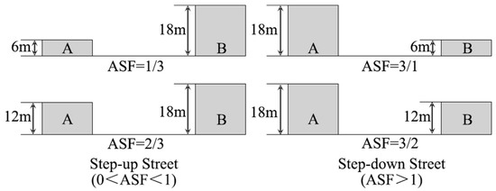
Figure 4.
An asymmetric street plan.
The study focuses on the influence of the road green belt shape on the airflow at the pedestrian breathing height in the street canyon (Y/H = 1.5), establishing the same road width and plant configuration as set. In the “Code for the Design of Urban Roads”, the “width of motor vehicle lanes and pavement” stipulates that the width of a single lane should not be less than 3.5 m [27] but, in reality, most motor vehicle lanes are a two-way four-lane road [20], so the more common two-way road is selected in this case. With four lanes, the width is stipulated to be 14 m; the “non-motor vehicle lane width” in the “Code for Design of Urban Road Engineering” should not be less than 3.5 m [28], so in this scheme, the width is designed to be 3.5 m; according to the layout of the road green belt (the spacing and the number of green belts), we established 5 sets of scenes: the first space is treeless and without green belts, while the other four use green-belt layouts with 4 different green-belt widths (Figure 5). The “Green Belt Design for Vehicles” in the “Code for Greening Planning and Design of Urban Roads” stipulates that the width of the green belts for planting trees should not be less than 1.5 m [29]; therefore, their widths are set at one board and two green belts, respectively (Spa1-2 = 9 m), the two-plate three-belt type (Spa2-3 = 6 m), the three-plate four-belt type (Spa3-4 = 2.75 m), and the four-plate five-belt type (Spa4-5 = 2.25 m).
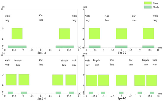
Figure 5.
Schematic diagram of the road green belt scenarios.
In previous studies, the optimal configuration for reducing particulate matter with vegetation is trees, shrubs, and grass [18], and the reduction effect from a shrub height of 0–2 m is the best. In reality, most of the street canopy width is 5 m, and the plant spacing and height are about 5–8 m [30]; at the same time, in order to facilitate the simulation calculation when the convergence is normal, the canopy shape of the trees in the street canyon is simplified as a 1-m cube.
2.3. Control Equations and Boundary Conditions
Assuming that the airflow is an incompressible fluid, the turbulence model uses a standard k-ε two-equation model. The controlling equations of the continuity equations, the momentum equations, the k equations, and the ε equations are as follows ((1)–(4)):
where ui represents speed; xi is the spatial coordinate; i is the direction angle marker, which can be taken as 1,2,3; p is the air pressure; ρ (kg/m3) is the fluid density (air density); νe is the effective viscosity; ν is the kinematic viscosity; νt is the turbulent viscosity; σk and σε are the plant numbers; Cμ, Cε1, and Cε2 are dimensionless constants (their values are 0.09, 1.42, and 1.92, respectively); S, Sk, and Sε are the momentum source term, the turbulent flow energy term, and the turbulent dissipation rate source term, respectively, which are used to express the changes produced by the flow of airflow through the leaves and branches of the plant. The specific formula is shown in (5):
The layout adopts a hexahedral grid, and the number of grids is set to 256 × 63 × 98, totaling 1,562,022 points. Dense grids are allocated in and around the street canyon to obtain more detailed numerical solutions. In order to ensure normal convergence, we improved the pedestrian breathing surface. Regarding the calculation accuracy, in terms of the grid setting requirements of other scholars, the grid expansion rate used in regions with high gradients should be lower than 1.3 [31].
The boundary conditions are shown in (Figure 6): the inlet boundary is the velocity inlet; the neutral atmospheric boundary layer is simulated and the gradient wind speed is used [22,23,24,25]; the flow velocity at the height of the undisturbed inlet silhouette edge layer is 7 m/s, and the friction velocity is 0.52 m/s, while the horizontal roof velocity is 4.65 m/s (18 m), and the ground roughness () is 0.3; trees are regarded as uniform porous media. For the purposes of this paper, we adopted the vegetation modeling concept proposed by Gromke et al. The source term method establishes the effect of porous media on airflow, and its blocking effect on air is expressed by the pressure loss coefficient (m−1). This represents low crown porosity, corresponding to = 200 m−1: the outlet boundary is the flow outlet; the top and side of the computational domain are symmetrical boundaries; the bottom of the computational domain and the building walls are non-slip wall boundaries.
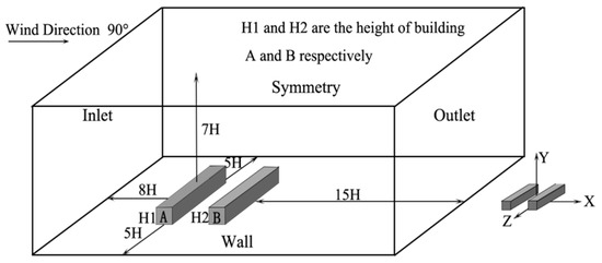
Figure 6.
Boundary conditions.
2.4. Simulation Results and Verification
There are many factors beyond the researcher’s control in field measurements, such as pedestrian interference, the accuracy of the measured street canyon, and other road facilities that will affect the accuracy of the measured results; also, the size and accuracy of the model in the simulation scheme cannot be compared with the actual street canyon. The size of the simulation scheme is exactly the same, so there is a certain disparity between the results of the simulation scheme and the measured values in the field. It was observed that the average errors of the overall monitoring surface at a height of 1.5 m and 6 m are 0.9 and 0.7, respectively, and the corresponding average error percentages are 22% and 25%, respectively. The maximum error velocity is C2 and G2 on the windward side, respectively. The monitoring points are 0.15 and 0.21, respectively, and the corresponding error percentages are 34% and 45%, respectively.
However, as a whole, comparing the data of each monitored point at different heights, it can be seen that the characteristics and trends of airflow velocity changes between the two are basically the same. Therefore, the calculation model and simulation parameters of the ANSYS FLUENT software effectively reflect the characteristics and trends of airflow in the street valley. The data fluctuation range of each monitoring point was recorded, then the median value was used with the measured data to obtain a line graph of comparative changes (Figure 7).
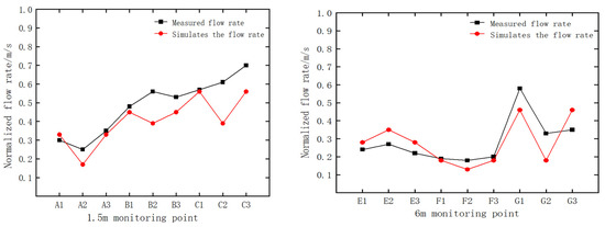
Figure 7.
Line diagram of the height disparity at 1.5 m (left) and 6 m (right).
2.5. Evaluation Indicators
The flow velocity characteristic distribution index is similar to the air distribution characteristic index (ADPI) in the Green Building Evaluation Standard. In this indicator, a wind speed of less than 5 m/s is considered to be a comfortable wind speed [24]; however, if the outdoor wind speed is too little/great in summer/winter will cause pedestrian discomfort.
Therefore, the ideal wind speed in this paper is taken as 1–4 m/s [32]. This reflects the degree of impact on the comfort of pedestrians after the green belt is set. After the airflow velocity, U, is obtained by CFD calculation, it is scaled to fall within a specific interval, making the calculation more accurate.
In order to obtain the ideal flow velocity ratio area of each scenario, the flow velocity is shown as 5 m/s for the purposes of normalization (Equation (1)). Therefore, the ideal normalized flow velocity range in this paper is 0.2–0.8 m/s. Focusing on the analysis of the airflow velocity at the pedestrian breathing zone, for a Spa green belt, a scenario without a green belt, and 4 road green-belt scenarios (Spa 1-2, Spa 2-3, Spa 3-4) in the step-up/step-down street canyon scheme (Spa 4-5), we performed a statistical analysis of the horizontal plane of the pedestrian breathing zone, and obtained the normalized flow velocity cloud map (U+) under different schemes, respectively:
We calculated the degree of influence of the four-road green-belt scenario on airflow at the pedestrian breathing zone (Equations (2) and (3)). According to the statistical data, we calculated the average degrees of influence of different green-belt scenarios on airflow at the pedestrian breathing height (Equation (4)). If the result is a positive number/negative number, this form of green belt promotes/hinders airflow:
In the formulae, N is the grid number of pedestrian breathing planes in the street canyon, which is 21,578; is the road green belt scenario; and j is the sample point.
3. Measurement Results and Interpretation
3.1. Reference Case without a Green Belt—The Influence of Airflow
The flow velocity values of the plane streamline diagram and the three-dimensional flow field diagram at Z/H = 0 m, X/W = 0 m, and pedestrian breathing height Y/H = 1.5 m in the middle of different types of street canyons were extracted (Figure 8), and after comparative analysis Obtain the distribution trend of the airflow field in the empty street canyon.
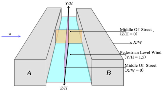
Figure 8.
Schematic diagram of the monitoring plane.
Step-Up Street with ASF = 1/3 and 2/3
Figure 9 and Figure 10 show the plane streamline diagram and the three-dimensional flow field diagram at different positions in the Spa green belt, in the step-up street with ASF = 1/3 and 2/3, respectively.
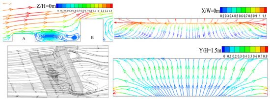
Figure 9.
Plane streamline diagram and three-dimensional flow field diagram in the step-up street with an ASF = 1/3.
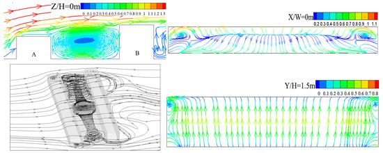
Figure 10.
Plane streamline diagram and three-dimensional flow field diagram in the step-up street with an ASF = 2/3.
From the plane streamline diagram at Z/H = 0 m, it can be seen that when the step-up street scheme is set at ASF = 1/3, two eddies with different directions and sizes are formed on the windward side and the leeward side, respectively, while the vortex centers are located on the roof of the downstream building and the static wind zone is formed at that point.
It can be seen from the three-dimensional flow field diagram that the height of Building A is relatively low, while the airflow field inside the street canyon is mainly affected by the flow around the roof. Part of the flow around the street is blocked by the windward side wall and flows out of the street canyon at the corner behind Building B. An angular vortex is formed; the other part sinks into the street canyon and then climbs to the roof of Building A around the obstacles of the ground and the leeward side. When it climbs to the height of the roof, it meets the strong airflow on the roof, forcing the rising airflow to turn downward. The windward and leeward walls form two eddy currents of different directions and sizes.
It can be seen from the plane streamline diagram at X/W = 0 m that part of the airflow flows out of the street canyon from the direction of the roof; then, the flow velocity increases continuously and reaches the maximum value. The other part of the airflow flows from the middle to the ground at both ends; the closer it is to the ground, the smaller the flow velocity, and a static wind area is formed near the ground.
It can be seen from the plane streamline diagram at Y/H = 1.5 m that the airflow sinks from the windward side and the velocity increases when passing over the ground. The velocity here is higher than on the windward side and the leeward side; at this point, part of it flows to the leeward side and the other part flows to the windward side. Both ends form an angular vortex and the flow velocity reaches maximum.
From the plane streamline diagram at Z/H = 0 m, it can be seen that when the ASF rises to 2/3, there is only one clockwise vortex in the street canyon; the vortex center shifts to the middle of the street canyon, and a quiet wind area is formed there. The airflow velocity in the middle and near the ground is higher than in other positions. It can be seen from the flow field diagram that the building on the leeward side is raised and angular vortices appear at both ends.
It can be seen from the plane streamline diagram at X/W = 0 m that that part of the airflow flows out of the street canyon from both ends of the roof, while the flow velocity increases continuously and reaches the maximum value on both sides. Another part of the airflow travels from the middle to the ground at both ends. The airflow tends to decrease at first and then increase, forming a static wind area on the roof of Building A, after which the flow velocity increases continuously and the flow velocity increases as it moves closer to the ground.
From the plane streamline diagram at Y/H = 1.5 m, it can be seen that the airflow sinks from the windward side; when passing over the ground, the flow velocity increases. The two ends form angular vortices, while the other part flows into the two ends of the windward side.
Step-Down Street Canyon ASF = 3/1 and 3/2
Figure 11 and Figure 12 are the plane streamline diagrams of different positions in the empty street canyon without a green belt and in the step-down street canyon with ASF=3/1 and 3/2, respectively.
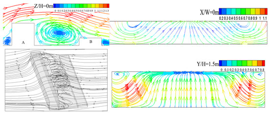
Figure 11.
Plane streamline diagram and 3D flow field diagram in the step-down street canyon with ASF = 3/1.
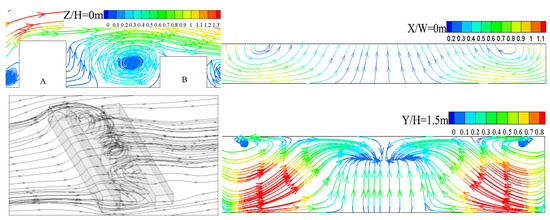
Figure 12.
Plane streamline diagram and 3D flow field diagram in a decreasing street canyon with ASF = 3/2.
It can be seen from the plane streamline diagram at Z/H = 0 m that when the decreasing street canyon scheme ASF= 1/3, there is a clockwise vortex in the middle of the street canyon and above the roof of building B, with a clockwise flow and a quiet wind area. Here, the near-surface airflow velocity near the middle of the street canyon is generally higher than that on the windward and leeward sides.
It can be seen from the three-dimensional flow field diagram that the airflow carried by the angular vortex at the corner of the leeward side increases after being blocked by the windward side wall and forms an extreme value area; then, the airflow climbs from the leeward side wall to the roof of Building A after it meets the airflow around the roof of Building A. This turns the airflow downward, creating a vortex inside the street canyon.
From the plane streamline diagram where X/W = 0 m, it can be seen that the airflow in the street canyon first flows from the roofs at both ends to the ground of the street canyon and then flows back to the roof. In the middle of the valley, the flow rate is increasing.
It can be seen from the plane streamline diagram at Y/H = 1.5 m that the airflow carried by the angular vortices at both ends increases gradually through the blocking flow velocity of the windward side wall and the ground, then it flows to the middle of the street canyon, forming a flow velocity where both ends > middle > windward side > leeward. On both sides of the street canyon, a “vent effect” is formed. A “wind shadow effect” is formed on the leeward side.
It can be seen from the plane streamline diagram at Z/H = 0 m that when the ASF drops to 3/2, the center of the vortex moves down to the roof of the downstream building and shifts to the windward side, while the flow velocity on the windward side is higher than that on the leeward side.
It can be seen from the three-dimensional flow field diagram that the building on the windward side is raised and the roof’s sinking airflow is blocked by the windward wall. Part of the airflow flows out of the street canyon, forming a low-value area near the middle of the street canyon, while the corner vortices at both ends are blocked by the windward-side buildings. The local flow velocity at both ends of the back street canyon increases and the velocity near the ground is higher, so that an extreme area is formed at both ends of the street canyon and the flow around the roof sinks after the windward side wall sinks, while the corner vortices at both ends and the leeward side sink. The air currents meet, and their interaction finally converges on the windward side and forms a vortex; the center of the vortex is offset to the downstream building roof.
It can be seen from the plane streamline diagram, at X/W = 0 m and Y/H = 1.5 m, that this is basically the same as the 3/1 street canyon scheme, but the comparison shows that the flow velocity in the middle of the street canyon is lower; the airflow is carried by the angular vortices at both ends. After being blocked by the windward side wall and the ground, the flow velocity gradually increases and the overall rate is higher than that of the 3/1 street canyon scheme. When passing over the ground, the flow velocity reaches the maximum and forms a “tuyere effect”, then flows into the middle of the leeward side, and finally flows into the windward side after being blocked by the leeward side wall.
3.2. Reference Case with Green Belt—Influence of Pedestrian-Level Wind
Step-Up Street with ASF = 1/3 and 2/3
Figure 13 and Figure 14 show the empty street canyon in the step-up and step-down street canyon schemes with different building height ratios on both sides; the normalized flow velocity cloud map U+ of the plane in the four green-belt scenarios of (, , and ), respectively, and .
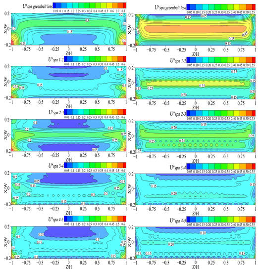
Figure 13.
The normalized flow velocity diagram U+ at the breathing height of people in different green-belt scenarios, in an ASF = 1/3 (left) and 2/3 (right) step-up street.
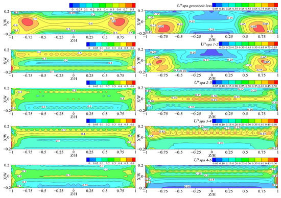
Figure 14.
The normalized flow velocity diagram U+ at the pedestrian breathing zone, with different road green-belt scenarios in the step-down street, with ASF = 3/1 (left) and 3/2 (right).
It can be seen from Figure 10 that when ASF = 1/3 (on the left side of the figure), after the green belt is set, the airflow velocity on the back side is lower than that on the windward side; the low-value area of the velocity at both ends of the leeward side disappears and appears on the leeward side and near the middle. A low-value area of flow velocity is formed nearby, and the flow velocity at both ends of the windward side reaches the maximum value. The specific manifestations are as follows: (1) the maximum flow velocity area is near the two ends of the windward side of the street canyon (Z/H = ±1, X/W = −0.2). The distribution range with a normal flow velocity of 0.5–0.8 decreases with the increase in the green belt, and the distribution range is the largest for Spa2-3. (2) The minimum flow velocity area is located on the leeward side of the street canyon (Z/H = ±0.5, X/W =-0.2). Spa2-3 has an additional windward side (Z/H = ±0.5, X/W = −0.2), while the distribution range of the normalized flow velocity at ≤ 0.05 increases with the increase in the green belt, while the leeward side continues to increase, with the largest distribution in the form of Spa2-3.
When ASF = 2/3 (on the right side of the figure), the velocity trend on the leeward side and the windward side is consistent with that of the scheme with ASF = 1/3, but there are additional low-velocity areas at both ends of the street canyon. The velocity in the middle of the street canyon is generally higher than that in other locations. The specific performance is as follows: (1) the maximum flow velocity area is located near the two ends and the middle of the windward side of the street canyon. The distribution range of the normalized flow velocity of 0.20–0.55 is the largest in Spa2-3, where the windward side gradually decreases with the increase in the green belt. (2) The minimum flow velocity area is located on the leeward side (Z/H = ±1, X/W = 0.2) and near both ends, while the distribution range of normalized flow velocity ≤ 0.1 increases with the green belt. While it continues to increase, the distribution range shifts from the middle to the windward and leeward sides of the street canyon.
3.3. Reference Case with Green Belt—Influence of Pedestrian-Level Wind
Step-Down Street Canyon ASF = 3/1 and 3/2
Figure 14 shows that when ASF = 3/1 (on the left side of the figure), after the green belt is set, the flow velocity on the leeward side is higher than that on the windward side, and the flow velocity at the middle and both ends of the windward side reaches the maximum value. In the scenario for Spa1-2, the flow velocity in the middle of the street canyon is the smallest. With the increase in the green belt, the flow velocity gradually shifts to the windward side. The specific performance is as follows: (1) the maximum flow velocity areas are located at both ends of the windward side of the street canyon (Z/H = ±1, X/W = −0.1), while the distribution range of the normalized flow velocity of 0.4–0.8 gradually decreases on the windward side with the increase in the green belt, until it disappears. The distribution ranges of Spa1–2 and Spa3–4 are generally higher than that of Spa2-3 and Spa4-5; (2) The minimum velocity area is located in the middle of the street canyon and near the windward side (Z/H = ±0.75, X/W = 0). On the leeward side, the largest distribution area is in Spa4-5.
When ASF = 3/2 (on the right side of the figure), after the green belt is set, the trend of flow velocity on the leeward side and the windward side is consistent with that of 3/2 of the street canyon, and the flow velocity at the middle and both ends of the windward side reaches the maximum value, but in the leeward side of Spa1-2 The side velocity is lower than the windward side, but with the increase in the green belt, the windward velocity reaches the minimum value and forms a quiet wind area, which is shown as follows: (1) the maximum velocity area is located at both ends of the windward side of the street canyon (X/W = ±0.75), the distribution range of normalized flow velocity at ≥ 0.5 increases with the increase in the green belt; (2) the minimum flow velocity area is located on the leeward side in the form of Spa1-2, with the other road scenarios located on the windward side, while the normalized flow velocity is ≤ 0.1 The distribution range first decreased and then increased with the increase in the green belt, and the windward side was gradually higher than the leeward side.
4. Analysis and Discussion
4.1. Experimental Analysis
Similar studies (36) have shown that in uniform street canyons, pedestrian comfort decreases with increasing street width. Figure 15 shows the plane streamline diagram at Z/H = 0 in the middle of the street canyon for the four green-belt scenarios in the step-up and step-down street canyon scheme, with different building height ratios.
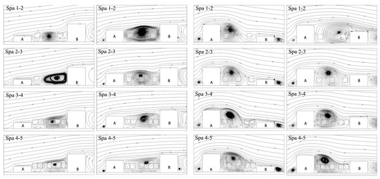
Figure 15.
Plane streamline diagram at Z/H = 0 with different road green-belt scenarios.
It can be seen from Figure 12 that the reason for the difference is that when the step-up street canyon ASF = 1/3, the green belt causes the turbulence at the roof of Building A to sink on the leeward side, increasing the airflow infiltrating into the middle, while the airflow at both ends is affected by the green belt. After blocking, the airflow to the interior of the street canyon and the windward side is reduced, so extreme airflow areas are formed near the leeward side and the windward side of the two ends, which are most evident in the scenario of Spa4-5; as the building height on the leeward side rises, the ASF rises to At 2/3, the turbulence at the roof is reduced by the sinking flow intensity on the B side of the building, and the increase in green belts weakens the airflow traveling into the middle of the street canyon at both ends, resulting in the infiltrating airflow no longer having enough potential energy to flow from the windward side. The side vortex moves to the leeward side, causing the center of the vortex to gradually shift to the windward side, forming a low-velocity area in the middle of the street and near the leeward side, causing the overall airflow velocity on the leeward side to be lower than that on the windward side.
When ASF = 3/1 in the step-down street canyon, the bypass flow at the roof of Building A is blocked by the trees on the windward side and then slopes and sinks in the middle, to flow into the windward and the leeward side, respectively. The leeward wall uplifts the airflow moving into the leeward side. It meets the strong airflow on the roof of building A and turns downward to form a vortex on the leeward side. The airflow carried by the angular vortex is blocked by the green belt on the leeward side. It then sinks into the street canyon, increasing the airflow velocity on the leeward side to create the maximum velocity. This high area is most evident in the form of Spa1-2. With the increase in the green belt, the airflow carried by the angular vortex into the middle of the street canyon gradually decreases, and a maximum velocity reduction area is formed in the middle of the street canyon and near the two ends, which continues to the windward side. When it is offset, as the building on the windward side rises, the airflow at the roof of Building B, sinking from the leeward wall, increases. The maximum velocity increase area is formed in the middle of the street canyon and near the windward side. With the increase in the green belt by Building A, the airflow at the roof changed from sinking at the leeward wall to sinking in the middle and the position of the vortex gradually shifted to the leeward side, causing the overall airflow velocity on the leeward side of the street canyon to be higher than that on the windward side.
4.2. Evaluation Methodology
The average airflow intensity and ideal wind speed ratio area index are used to evaluate the plane, by which means statistics and sorting are obtained (Table 1 and Table 2).

Table 1.
Average airflow intensity percentage of pedestrian-level wind under different green belt schemes.

Table 2.
Area/percentage of ideal flow velocity under different street canyon schemes.
It can be seen from Table 1 that the three-plate and four-belt type of step-down street canyon scheme with ASF = 3/2 can promote airflow at pedestrian breathing height (4.76%), while the other street canyon schemes (1/3, 2/3, and 3/1) all present a different degree of obstruction, among which the four-plate and five-belt type has the most significant obstruction effect. The specific performance is as follows: (1) Spa2-3 of the step-up street scheme has a minor obstructive effect on the airflow. The airflow around the roof on the windward side of the valley passes through the gap between the trees on the leeward side and is blocked by the central green belt, then sinks to the interior of the street canyon, increasing airflow in the middle of the street canyon. (2) The overall hindering effect of Spa1-2 and Spa3-4 of the step-down street canyon scheme is smaller than that of Spa2-3 and Spa4-5. The comparative analysis found that the scenario without green belts in the middle of the street canyon can allow the airflow of the angular vortex to penetrate the middle of the street canyon, promoting the movement of the vertical vortex inside the street canyon and the horizontal angular vortex at both ends and reducing the “wind-shadow effect” in the middle of the street canyon, as well as the “tuyere effect” at both ends.
It can be seen from Table 2 that after the green belt is set, only the pedestrian breathing height treatment in the step-down street canyon scheme with ASF = 3/2 increases the proportion of wind speed, while the proportion of other street canyon schemes decreases, of which Spa4-5 is the least influential. The specific performance is as follows: (1) under the step-up street scheme, the proportion of Spa2-3 is higher than that of other green belts; (2) under the step-down street canyon scheme, Spa1-2 and Spa3-4 have the highest proportions.
5. Conclusions
Street canyons are the basic units that make up a city, and road green belts are the core content of road green-space planning [18]. Previous studies have shown that green belts have both positive and negative effects on airflow field and air quality in street canyons, depending on the street canyon and green belt characteristics [7,8,9,10,11]; these characteristics cause the local flow and turbulence in street canyons to show strong spatial variation in both vertical and horizontal directions [11,12,13,14]. The experimental results simulated in this paper verify the existing conclusions of the literature.
However, in today’s increasingly extreme street canyon environment, it is important to propose a reasonable, forward-looking plan for road green-belt scenarios for different street canyon geometric types in terms of the layout of existing urban buildings. This paper uses CFD technology to simulate the airflow field under four road green-belt scenarios in asymmetric streets, with different building ratios on both sides of the street canyon. The results and our analysis prompt the following conclusions:
- (1)
- In different empty street canyon schemes, the quiet wind area is located near the roof of the downstream building. In the street canyon scheme where ASF = 1/3, the closer to the ground, the lower the flow velocity measured, but in other street canyon schemes (2/3, 3/1, and 3/2), the closer to the ground, the higher the flow velocity measured; after the green belt is set, the airflow on the windward side in the step-up street scheme is higher than that on the leeward side, while the airflow on the leeward side of the step-down street canyon is higher than that on the windward side.
- (2)
- From the average airflow intensity point of view, only the three-slab and four-belt green belt in the step-down street canyon with ASF = 3/2 can promote airflow at the pedestrian breathing height (4.76%), while other street canyon schemes all demonstrate different degrees of obstruction. Among them, the four-plate and five-belt type has the most significant obstruction effect, and the specific performance is as follows: (1) the two-plate and three-belt type green belt in the step-up street scheme has the least obstruction effect on the airflow; (2) in the step-down street canyon scheme, the one-plate two-belt type and the three-plate four-belt type have the least hindering effect.
- (3)
- From the perspective of the ideal wind speed ratio, after the green belt is set, only the pedestrian respiration height treatment in the step-down street canyon scheme with ASF = 3/2 increases the proportion of the wind speed, while the other street canyon schemes all reduce the area. The area of the four-board and five-belt type is the smallest, and the specific performance is as follows: (1) the ideal wind speed proportion of the two-board and three-belt green belt under the step-up street scheme is generally higher than that of other green-belt schemes; (2) under the step-down street canyon scheme, one-board two-belt and three-board four-belt accounted for the highest area.
- (4)
- The step-up street adopts the green-belt scheme of two slabs and three belts, which can increase the flow around the roof on the windward side of the street canyon and flow into the street canyon, effectively reducing the area of the quiet wind area in the street canyon; the step-down street canyon adopts one slab and two belts, while the three-plate and four-belt green belt can allow the corner vortices at both ends to carry more airflow into the street canyon, enhance the exchange between turbulent flow and vertical airflow in the street canyon, and effectively reduce the “wind shadow effect” in the middle of the street canyon and “wind shadow effect” at the two ends of the street canyon, creating a wind effect.
In this paper, a numerical simulation method is used to analyze the influence of the road green belt scheme on airflow at pedestrian breathing height in an asymmetric street through variable controls to improve human comfort. However, its purpose is also affected by solar radiation. This paper focuses on the layout of the road green belt, but the size of the porosity caused by the seasonal changes of the trees is also an essential factor. More in-depth analysis is needed in the future to provide more detailed guidance for road greening, planning, and design. Furthermore, the results obtained can serve as a basis for urban planners, landscape architects, and professionals in other related fields in the design and planning of road greening.
Author Contributions
Conceptualization, F.Z. and D.S.; methodology, X.R.; software, F.Z. and D.S.; validation, F.Z., Z.C. and D.S.; formal analysis, H.Z. and X.R.; writing—original draft preparation, F.Z. and D.S.; writing—review and editing, F.Z. and D.S.; visualization, F.Z. and D.S.; supervision, Z.C. All authors have read and agreed to the published version of the manuscript.
Funding
The scientific research project of the Zhejiang Provincial Department of Education/“Exploring the influence of tree species density layout on indoor natural ventilation, based on numerical simulation” (No. YZ20200010).
Institutional Review Board Statement
Not applicable.
Informed Consent Statement
Not applicable.
Data Availability Statement
To obtain data for our study please contact the authors via email.
Acknowledgments
We are thankful to all our colleagues and co-authors fo their very valued contributions to this work. The authors are also very appreciative of the reviewers comments which helped better the manuscript.
Conflicts of Interest
The authors declare no conflict of interest.
References
- Nations, U.; Affairs, S.; Division, P. World Urbanization Prospects: The 2014 Revision, Highlights; United Nations, Department of Economic and Social Affairs: New York, NY, USA, 2014; ISBN 978-921-151-517-6. [Google Scholar]
- Population Division of the Department of Economic and Social Affairs of the United Nations Secretariat, World Urbanization Prospects. Available online: http://esa.un.org/wpp/Excel-Data/population.htm (accessed on 15 March 2022).
- The Ministry of Housing and Urban-Rural Development and 15 other departments issued the Opinions on Strengthening the Green and Low-carbon Construction of Counties and Cities. Available online: http://www.gov.cn/zhengce/zhengceku/2021-06/08/content_5616290.htm (accessed on 17 March 2022).
- van Hooff, T.; Blocken, B.; Tominaga, Y. On the accuracy of CFD simulations of cross-ventilation flows for a generic isolated building: Comparison of RANS, LES and experiments. Build. Environ. 2017, 114, 148–165. [Google Scholar] [CrossRef]
- Jiao, M.; Zhou, W.; Zheng, Z.; Hu, X. Patch size of trees affectsits cooling effectiveness: A perspective from shading and transpiration processes. Agric. For. Meteorol. 2017, 247, 293–299. [Google Scholar] [CrossRef]
- Toparlar, Y.; Blocken, B.; Vos, P.; van Heijst, G.; Janssen, W.; van Hooff, T.; Montazeri, H.; Timmermans, H. CFD simulation and validation of urban microclimate: A case study for Bergpolder Zuid, Rotterdam. Build. Environ. 2015, 83, 79–90. [Google Scholar] [CrossRef]
- Abhijith, K.; Kumar, P.; Gallagher, J.; McNabola, A.; Baldauf, R.; Pilla, F.; Broderick, B.; Di Sabatino, S.; Pulvirenti, B. Air pollution abatement performances of green infrastructure in open road and built-up street canyon environments—A review. Atmos. Environ. 2017, 162, 71–86. [Google Scholar] [CrossRef]
- Janhäll, S. Review on urban vegetation and particle air pollution—Deposition and dispersion. Atmos. Environ. 2015, 105, 130–137. [Google Scholar] [CrossRef]
- Wang, A.; Guo, Y.; Fang, Y.; Lu, K. Research on the horizontal reduction effect of urban roadside green belt on atmospheric particulate matter in a semi-arid area. Urban For. Urban Green. 2021, 68, 127449. [Google Scholar] [CrossRef]
- Vos, P.E.J.; Maiheu, B.; Vankerkom, J.; Janssen, S. Improving local air quality in cities: To tree or not to tree? Environ. Pollut. 2013, 183, 113–122. [Google Scholar] [CrossRef] [PubMed]
- Zheng, X.; Yang, J. Impact of moving traffic on pollutant transport in street canyons under perpendicular approach wind: An CFD analysis using large-eddy simulations. Sustain. Cities Soc. 2022, 82, 103911. [Google Scholar] [CrossRef]
- Salmond, J.A.; Williams, D.E.; Laing, G.; Kingham, S.; Dirks, K.; Longley, I.; Henshaw, G.S. The influence of vegetation on the horizontal and vertical distribution of pollutants in a street canyon. Sci. Total Environ. 2013, 443, 287–298. [Google Scholar] [CrossRef] [PubMed]
- Amorim, J.; Rodrigues, V.; Tavares, R.; Valente, J.; Borrego, C. CFD modelling of the aerodynamic effect of trees on urban air pollution dispersion. Sci. Total Environ. 2013, 461–462, 541–551. [Google Scholar] [CrossRef] [PubMed]
- Li, D. Study on the Law of Pollution Diffusion of Traffic Flow in Urban Streets and Valleys; Southwest Petroleum University: Chengdu, China, 2018. [Google Scholar]
- Oke, T.R. Street design and urban canopy layer climate. Energy Build. 1988, 11, 103–113. [Google Scholar] [CrossRef]
- He, L.; Hang, J.; Wang, X.; Lin, B.; Li, X.; Lan, G. Numerical investigations of flow and passive pollutant exposure in high-rise deep street canyons with various street aspect ratios and viaduct settings. Sci. Total Environ. 2017, 584–585, 189–206. [Google Scholar] [CrossRef] [PubMed]
- Miao, C.P.; Chen, W.; Cui, A.W.; Li, P.P.; Hu, Y.M.; He, X.Y. Research progress on the distribution of atmospheric pollutants in urban streets and valleys. Chin. J. Appl. Ecol. 2021, 32, 3377–3384. [Google Scholar] [CrossRef]
- Liu, J. Planning and Design of Urban Green Space System; China Architecture and Building Press: Beijing, China, 2004; ISBN 978-711-206-125-9. [Google Scholar]
- Blocken, B.; Janssen, W.; van Hooff, T. CFD simulation for pedestrian wind comfort and wind safety in urban areas: General decision framework and case study for the Eindhoven University campus. Environ. Model. Softw. 2012, 30, 15–34. [Google Scholar] [CrossRef]
- Guo, X.H.; Dai, F.; Yin, L.H. Simulation study on the reduction effect of road green belt planning and design on PM (2.5) based on ENVI-met. Landsc. Archit. 2018, 25, 75–80. [Google Scholar] [CrossRef]
- Vardoulakis, S.; Fisher, B.E.; Pericleous, K.; Gonzalez-Flesca, N. Modelling air quality in street canyons: A review. Atmos. Environ. 2003, 37, 155–182. [Google Scholar] [CrossRef]
- Concentration Data of Street Canyon, Internet Database. Available online: http://www.windforschung.de/CODASC.htm (accessed on 18 March 2022).
- Franke, J.; Hellsten, A.; Schlünzen, K.H.; Carissimo, B. Best Practice Guideline for the CFD Simulation of Flows in the Urban Environment; Cost Office Brussels: Brussels, Belgium, 2007. [Google Scholar]
- Tominaga, Y.; Mochida, A.; Yoshie, R.; Kataoka, H.; Nozu, T.; Yoshikawa, M.; Shirasawa, T. AIJ guidelines for practical applications of CFD to pedestrian wind environment around buildings. J. Wind Eng. Ind. Aerodyn. 2008, 96, 1749–1761. [Google Scholar] [CrossRef]
- Gromke, C. A vegetation modeling concept for Building and Environmental Aerodynamics wind tunnel tests and its application in pollutant dispersion studies. Environ. Pollut. 2011, 159, 2094–2099. [Google Scholar] [CrossRef]
- Assessment Standard for Green Building, GB/T50378-2019 ed.; Tongji University Press: Shanghai, China, 2019; ISBN 978-756-089-277-1.
- Urban Road Design Code, CJJ37_90 ed.; People’s Publishing House: Beijing, China, 1991; ISBN 978-151-121-404-9.
- Urban Road Engineering Design Code, CIJ37-2012 ed.; China Architecture and Building Press: Beijing, China, 2012; ISBN 151-122-176-6.
- Urban Road Greening Planning and Design Code, CJJ75-97 ed.; China Architecture and Architecture Press: Beijing, China, 1997; ISBN 151-121-468-0.
- Xu, H.; Zhao, J.J.; Li, H. Effects of road greenfield plant configuration on PM2.5 concentration distribution and attenuation. North. Hortic. 2016, 24, 65–69. [Google Scholar]
- Shen, X.Y. Effect of Spatial Layout of Trees on Air Flow Inside Typical Street Valleys; Fuzhou University: Fuzhou, China, 2018. [Google Scholar]
- Zhou, Y.C.; Fu, H.M.; Yang, H. Numerical simulation and evaluation of the influence of plants on the flow field of street valley. J. Donghua Univ. (Nat. Sci. Ed.) 2016, 42, 419–425. [Google Scholar]
Publisher’s Note: MDPI stays neutral with regard to jurisdictional claims in published maps and institutional affiliations. |
© 2022 by the authors. Licensee MDPI, Basel, Switzerland. This article is an open access article distributed under the terms and conditions of the Creative Commons Attribution (CC BY) license (https://creativecommons.org/licenses/by/4.0/).